Article

Frequency-Dependent Schroeder Allpass Filters

by
Sebastian J. Schlecht
Department of Signal Processing and Acoustics and Department of Media, Aalto University, 02150 Espoo, Finland
Appl. Sci. 2020, 10(1), 187; https://doi.org/10.3390/app10010187
Submission received: 30 November 2019 / Revised: 20 December 2019 / Accepted: 20 December 2019 / Published: 25 December 2019
(This article belongs to the Special Issue Digital Audio Effects)

Abstract

:
Since the introduction of feedforward–feedback comb allpass filters by Schroeder and Logan, its popularity has not diminished due to its computational efficiency and versatile applicability in artificial reverberation, decorrelation, and dispersive system design. In this work, we present an extension to the Schroeder allpass filter by introducing frequency-dependent feedforward and feedback gains while maintaining the allpass characteristic. By this, we directly improve upon the design of Dahl and Jot which exhibits a frequency-dependent absorption but does not preserve the allpass property. At the same time, we also improve upon Gerzon’s allpass filter as our design is both less restrictive and computationally more efficient. We provide a complete derivation of the filter structure and its properties. Furthermore, we illustrate the usefulness of the structure by designing an allpass decorrelation filter with frequency-dependent decay characteristics.

1. Introduction

Since the introduction of feedforward–feedback comb allpass filters by Schroeder and Logan [1], its popularity has not diminished due to its computational efficiency and versatile applicability in artificial reverberation [2]. Compared to general high-order allpass filters [3], the Schroeder allpass is a sparse filter, which is less flexible, but more computationally efficient. Multiple Schroeder allpass filters can be combined in series or by nesting [4] to create more complex structures while retaining the allpass characteristic. Allpass filters can further be generalized to multiple input and output (MIMO) systems based on unitary networks [5] or feedback delay networks (FDNs) [6]. An ideal high-order allpass filter might possess the following properties: (a) being strictly allpass instead of an approximation; (b) good control of system pole locations while maintaining ease of design; and (c) efficient implementation independent from the total order. However, an inherent disadvantage of Schroeder allpass filters is the dependency between the dry-wet-ration and the decay time. Nonetheless, allpass filters were applied to with a wide range of roles including: (1) increasing the echo density as preprocessing to an artificial reverberator [1,7,8]; (2) increasing echo density of in the feedback loop of reverberators [5,9,10,11,12,13]; (3) decorrelation for widening the auditory image of a sound source [14,15,16,17]; (4) as reverberator in electro-acoustic reverberation enhancement systems [6,12,18,19]; and (5) dispersive system design [20]. In artificial reverberators and decorrelators, the allpass characteristic is most important when used as short diffusing filters. When used with longer decay times, only the local comb-like spectrum is perceived. For reverberation enhancement systems and feedback delay networks, the allpass characteristic is mathematically important to maintain the system stability.
In this work, we present an extension to the Schroeder allpass filter [1] by introducing frequency-dependent feedforward and feedback gains while maintaining the allpass characteristic. The problem addressed in this paper was already realized by Moorer [8] when he remarked: “This gives us the entertaining result that either [feedforward] and [feedback gain] must be FIR filters, or [the feedforward gain] must be an unstable filter when viewed in isolation.” and effectively concluded that it is unfeasible to employ an IIR filter. However, a few years earlier, Gerzon [5] showed that it is possible to apply some IIR filters with a more elaborate structure. In this paper, we show that indeed, it is possible to achieve the desired effect on the compact feedforward/-back structure with any FIR or IIR filter. By this, we directly improve upon the design of Dahl and Jot [11], which exhibits a frequency-dependent absorption but does not preserve the allpass property. At the same time, we also improve upon Gerzon’s allpass filter [5] as our design is both less restrictive and computationally more efficient.
The remaining manuscript is structured as follows. Section 2 introduces some filter design background and reviews related Schroeder allpass filter structures. In Section 3, we present the proposed frequency-dependent Schroeder allpass alongside an example case. We give a full derivation of the pole and zero locations depending on the feedforward and feedback gains. Section 4 presents an application of the proposed filter for decorrelation. The paper is then concluded in Section 5. For reproducibility, the MATLAB code to reproduce all data and figures are published at https://github.com/SebastianJiroSchlecht/FrequencyDependentSchroederAllpass.

2. Schroeder Allpass Filters

The Schroeder allpass filter has evolved into various forms since its induction in [1]. Here, we review important contributions by Schroeder and Logan [1], Gerzon [5] and Dahl and Jot [11]. First, however, we introduce some helpful mathematical background on digital allpass filters.

2.1. Filter Operations

Here, we recap some useful operations on filters for the upcoming derivations. In this manuscript, we assume that the filter coefficients are real-valued. Let b ( z ) be an FIR filter with order l b in the Z-domain, i.e., b ( z ) : = i = 0 l b b i z i . Here, : = denotes a definition. The flip operation · , which effectively flips the sequence of the filter coefficients, is then defined as
b ( z ) : = z l b b ( z 1 )
and the flip operation for an IIR filter g ( z ) : = b ( z ) a ( z ) is
g ( z ) : = b ( z ) a ( z ) .
A common notation of the flip operation is · ˜ , e.g., in [2]. We propose · to be a more intuitive alternative. The flip operation causes the zeros of a FIR filter to mirror at the unit circle, i.e., for any complex zero p C , we have the equivalence
b ( p ) = 0 b ( p 1 ) = 0 .
Consequently, for an IIR filter g ( z ) , only either g ( z ) or g ( z ) can be stable (except the marginally stable case where all poles are on the unit circle).
We define the complex conjugation operation · of a filter b ( z ) with real filter coefficients as
b ( z ) : = b ( z 1 ) = z l b b ( z )
such that we can write for the corresponding frequency response
b ( e ı ω ) = b ( e ı ω ) = ( b ( e ı ω ) ) ,
where ı = 1 and ω is the angular frequency in radians per sample. Thus, the complex conjugate filter has a complex conjugated frequency response. Please note that such a complex conjugated FIR filter is non-causal for l b > 0 .
Complex conjugated IIR filters can be realized by reversing the coefficient orders and compensating the order difference between numerator and denominator filters. Because
( g ( e ı ω ) ) = ( b ( e ı ω ) a ( e ı ω ) ) = e ı ω l b b ( e ı ω ) e ı ω l a a ( e ı ω ) = e ı ω ( l b l a ) g ( e ı ω ) ,
where l b and l a denote the filter order of the numerator and denominator, respectively, we define
g ( z ) : = z l b l a g ( z ) .
In the following, we review general allpass filters.

2.2. General Allpass Filters

With the previously introduced notation, it is straightforward to define the general allpass filter A ( z ) as
A ( z ) = a m + + a 1 z m + 1 + z m 1 + a 1 z 1 + + a m z m = D ( z ) D ( z ) ,
where D ( z ) = i = 0 m a i z i and a 0 = 1 . It can be seen easily that A ( z ) has a magnitude response with an allpass characteristic
| A ( e ı ω ) | = | D ( e ı ω ) D ( e ı ω ) | = | e ı ω m D ( e ı ω ) D ( e ı ω ) | = | ( D ( e ı ω ) ) D ( e ı ω ) | = 1 .
Because of the form (8), the poles p i and zeros q i of A ( z ) are reciprocal, i.e., p i 1 = q i for all i. The phase response of the allpass filter is
arg ( A ( e ı ω ) ) = m ω + 2 arg ( D ( e ı ω ) ) ,
where the group delay is
τ A ( ω ) = d arg ( A ( e ı ω ) ) d ω = m 2 d arg ( D ( e ı ω ) ) d ω .
The group delay of a single pole, single zero allpass filter A i ( z ) = α i + z 1 1 + α i z 1 is
τ A i ( ω ) = 1 α i 2 1 + 2 α i cos ω + α i 2 .
Any allpass filter can be factorized into first-order allpass filters, i.e., A ( z ) = i = 1 m A i ( z ) . Therefore, the total group delay is the sum of the group delay of the first-order components, i.e., τ A ( ω ) = i = 1 m τ A i ( ω ) . Next, we review the classic Schroeder allpass filter.

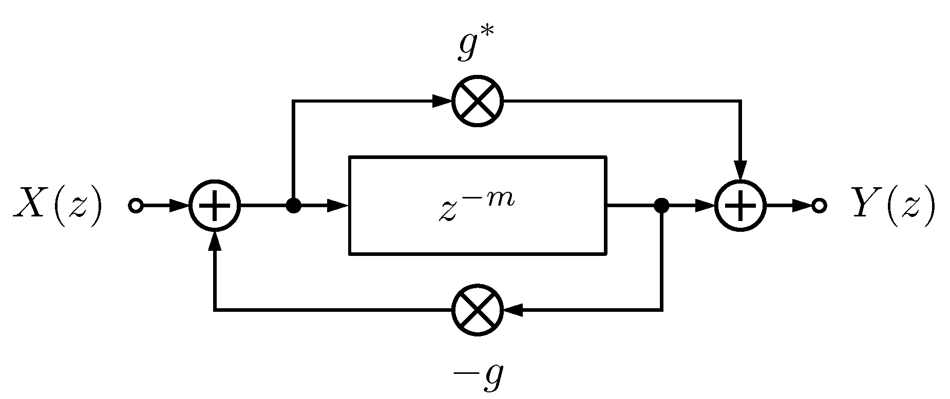
2.3. Classic Schroeder Allpass

Historically, delay feedback filters were one of the first means to create artificial reverberation due to their efficient implementation. However, they suffer from intense coloration (why they are also called comb filters). However, by merely introducing an additional feedforward path, Schroeder and Logan [1] were able to turn the comb filter into an allpass (see Figure 1).
The corresponding transfer function
H Schroeder ( z ) = X ( z ) Y ( z ) = g + z m 1 + g z m
is allpass (see (9)). Such a Schroeder allpass can be easily augmented by replacing the delay z m with an arbitrary allpass filter resulting in so-called nested allpasses [4]. The system poles p i of a Schroeder allpass are the scaled roots of unity, i.e., for 1 i m
p i = g 1 / m e ı 2 π i m .
Therefore, the pole frequencies arg ( p i ) are distributed uniformly, and the feedforward/-back gain g and delay m determine the pole magnitudes | p i | . The Schroeder allpass was then further generalized by Gerzon [5].

2.4. Gerzon’s Allpass

Whereas Gerzon’s brief contribution [5] introduced a multitude of generalizations to the allpass filter, here, we focus on the filtered feedforward/-back gains. Figure 2 shows Gerzon’s formulation of the Schroeder allpass.
The corresponding transfer function is
H Gerzon ( z ) = g ( z ) + ( g ( z ) g ( z ) g 2 ( z ) ) z m 1 + g ( z ) z m .
While for a scalar gain g, (13) and (15) are identical, they are subtly different for frequency-dependent gain g ( z ) . The original formulation (13) is only directly realizable for scalar gains because g ( z ) is non-causal for FIR filters or unstable for IIR filters. In contrast, Gerzon’s formulation (15) is realizable as long as the allpass filter g ( z ) g ( z ) is realizable. Due to (7), this allpass
g ( z ) g ( z ) = g ( z ) z l b l a g ( z ) = z l a l b b ( z ) a ( z ) a ( z ) b ( z )
is stable if g ( z ) is stable and the zeros of g ( z ) (and the zeros of b ( z ) , respectively) are outside the unit circle. In other words, g ( z ) needs to be a maximum phase IIR filter. While this is a step forward, also the computational cost increased: the Gerzon formulation (15) requires about three times of the operations of the Schroeder formulation (13). A further drawback with the IIR filter formulation is that the filter g ( z ) itself introduces new poles that are independent of the filter response design.

2.5. Dahl’s Absorbent Allpass

Schroeder allpass filters have been in use in larger feedback structures for artificial reverberation [4,10]. Dahl and Jot [11] realized that Schroeder allpass should have a similar decay characteristic as the overall reverberator to blend in well. To achieve this, they introduced a lowpass filter in series to the delay, which follows the overall reverberation time specification (see Figure 3).
The corresponding transfer function is
H Dahl ( z ) = X ( z ) Y ( z ) = g + z m c ( z ) 1 + g z m c ( z )
We illustrate the filter with the following example in Figure 4. The main delay is m = 50 , the feedforward/-back gain g = 0.7 and the low-shelving filter is
g ( z ) = 0.4644 1.2175 z 1 + 0.9000 z 2 1.0000 1.3799 z 1 + 0.5310 z 2 .
As also realized by the original authors, the resulting filter is no longer allpass.
The proposed application of the absorbent allpass filter is as additional diffusion in a feedback delay network (FDN) [11]. However, the pole decay rate of the FDN depends on the magnitude response of the recursion filter [21]. Figure 4b demonstrates that the FDN pole decay rate fluctuates highly which results in an uneven reverberation tail. Nonetheless, the set goal to construct a Schroeder allpass filter with a given decay characteristic serves further as an inspiration.

3. Proposed Frequency-Dependent Schroeder Allpass

In this section, we propose an improved frequency-dependent Schroeder allpass filter. First, we introduce the filter structure. Secondly, we study the pole-zero locations depending on the gain filter. Thirdly, we demonstrate the proposed filter with a numerical example.

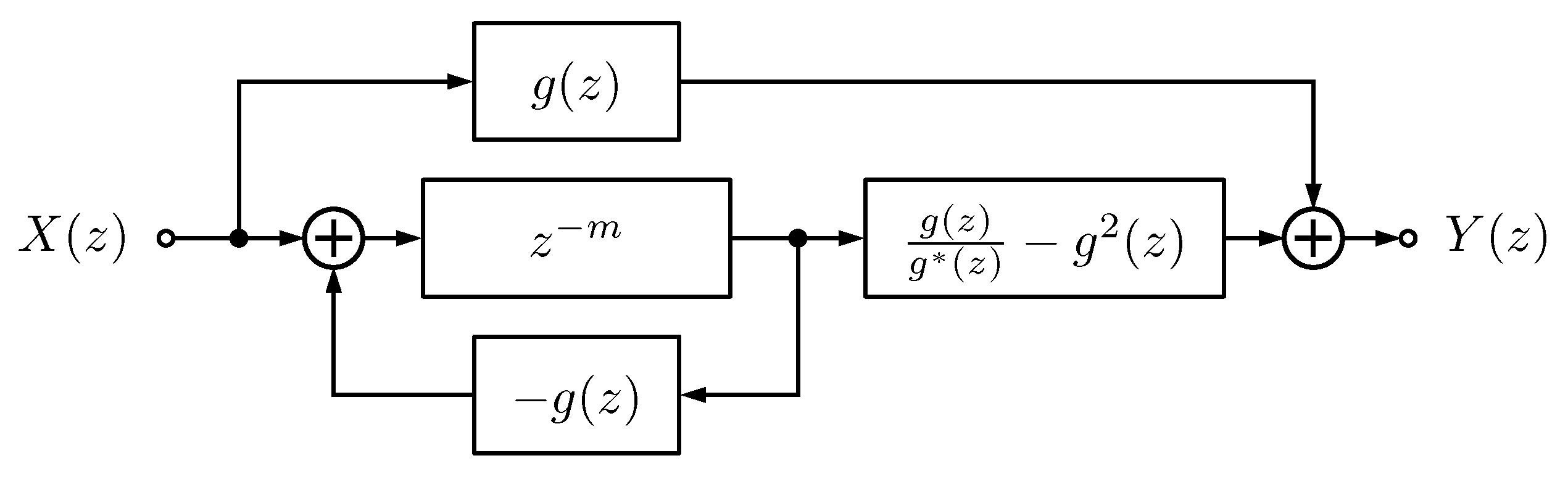
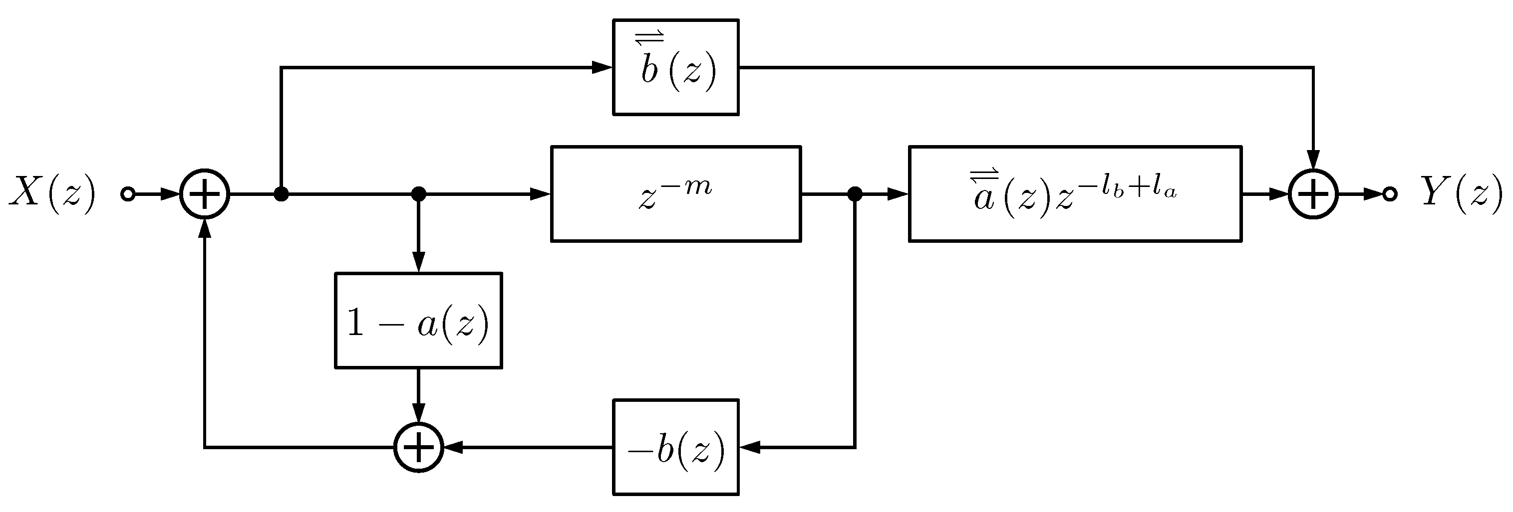
3.1. Filter Structure

We start with the filter version of the Schroeder formulation (13). Let g ( z ) : = b ( z ) a ( z ) be an IIR filter normalized such that a 0 = 1 . By substituting with the flip operation (1) we get
g ( z ) + z m 1 + g ( z ) z m = b ( z ) a ( z ) + z m 1 + b ( z ) a ( z ) z m = a ( z ) a ( z ) b ( z ) + a ( z ) z m a ( z ) + b ( z ) z m = a ( z ) a ( z ) b ( z ) z l b + a ( z ) z m + l a a ( z ) + b ( z ) z m .
Removing the allpass components a ( z ) / a ( z ) and z l b leaves us with
H Proposed ( z ) = b ( z ) + a ( z ) z m l b + l a a ( z ) + b ( z ) z m .
Due to (8), the proposed structure (20) is clearly allpass. Figure 5 shows the corresponding block diagram.
In contrast to (13) and (15), this formulation is realizable for any stable filter g ( z ) . A special case for g ( z ) = b ( z ) being a FIR filter is (see Figure 6):
H Proposed FIR ( z ) = b ( z ) + z m l b 1 + b ( z ) z m .
Each filter component is applied only once for the feedback and once for the feedforward path. In that sense, the computational cost of the proposed formulation is minimal. Therefore, it has about a third of the numerical operations compared to Gerzon’s formulation (15). As we have now established a flexible and efficient formulation, we proceed with studying the frequency-dependent character of the proposed allpass filter.

3.2. Poles and Group Delay
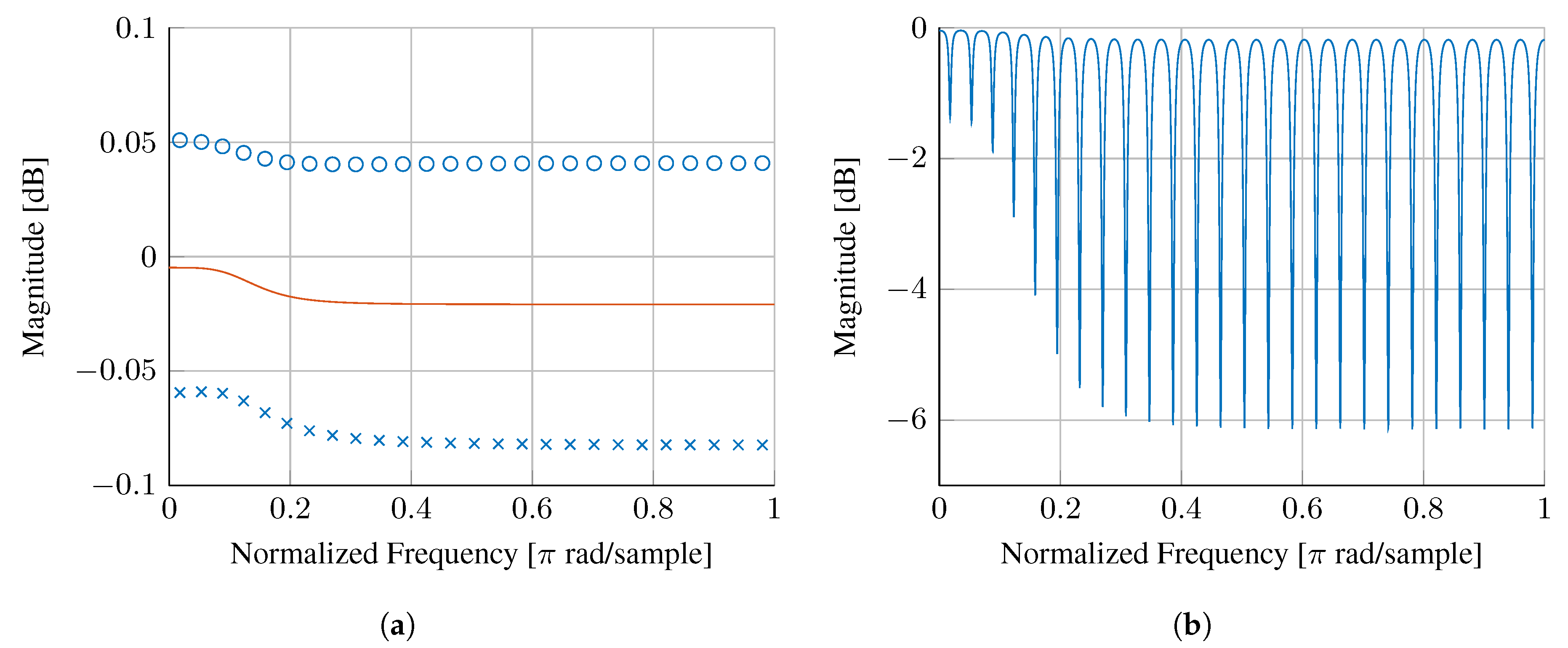
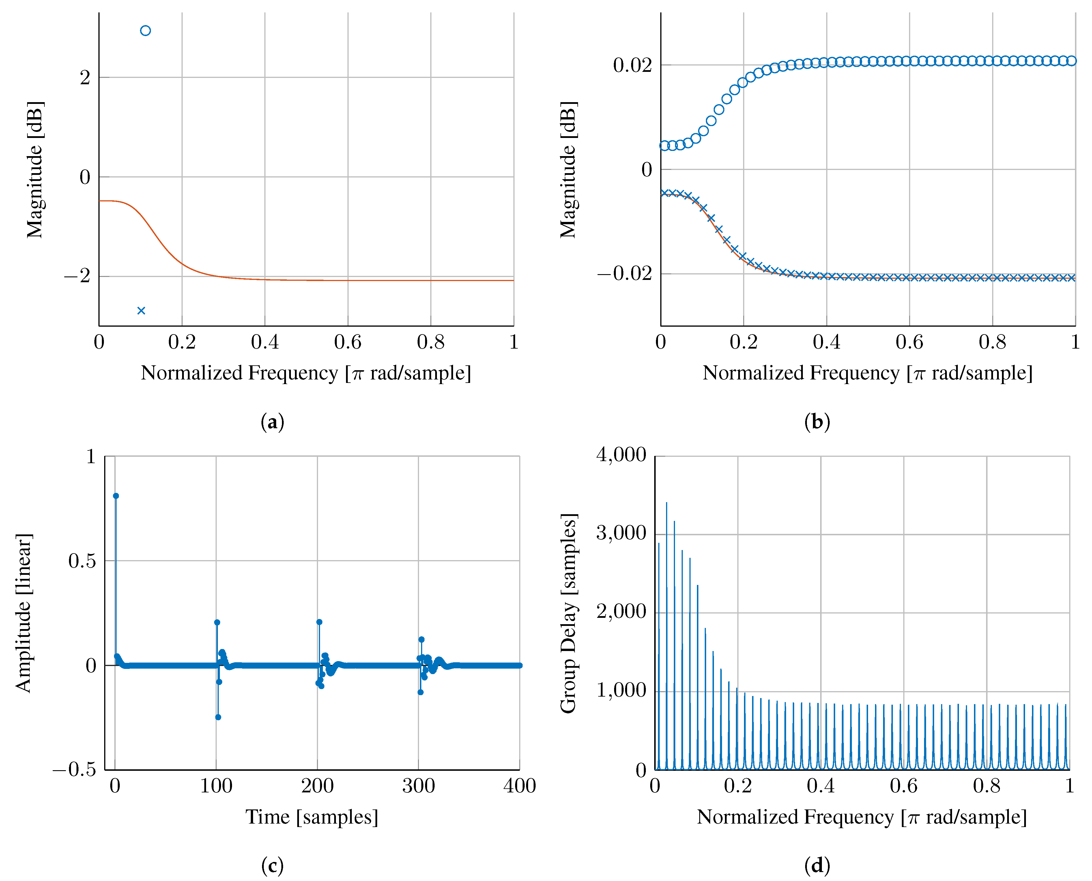
Given a feedforward/-back gain g ( z ) = b ( z ) / a ( z ) , the poles of the proposed allpass filter are given by the roots of the polynomial a ( z ) + b ( z ) z m in (20). For a scalar gain g, (14) gives the pole locations on a circle around the origin with a radius depending the delay length m and gain g. Based on Gerzon’s formulation, the system poles p i satisfy
1 + g ( p i ) p i m = 0 .
The filter g ( z ) is commonly idealized in having zero-phase and | g ( p i ) | | g ( e ı arg ( p i ) ) | such that all system poles lie on the line specified by | g ( e ı ω ) | 1 / m [21]. Although this is often not satisfied strictly, in many designs the filter delay of g ( z ) is small compared to the delay m and can be neglected. Therefore, stability of the complete allpass filter requires that g ( z ) is dampening, i.e., | g ( e ı ω ) | 1 . As a further consequence, poles are also approximately equidistributed along the frequencies. To illustrate this further, we next present two numerical examples.

3.3. Example

Figure 7 shows an example for the proposed frequency-dependent Schroeder allpass filter. The gain filter is
g ( z ) = 0.4119 1.0844 z 1 0.8101 z 2 1.0000 1.3931 z 1 + 0.5384 z 2
and m = 100 . Figure 7a is depicting the poles and zeros of g ( z ) alongside the resulting magnitude response | g ( e ı ω ) | . In Figure 7b, the magnitude response of | g ( z ) | 1 / m is plotted along the poles and zeros of the proposed Schroeder allpass in (20). The small deviation of the pole location from the gain curve is due to the neglected phase component. Figure 7c shows the resulting impulse response. While the overall structure resembles the classic Schroeder allpass, the pulses are smeared in time iteratively by passing through the gain filter g ( z ) . The last subplot, Figure 7d shows the group delay of the proposed Schroeder allpass. Comparing Figure 7d and Figure 7b, it is easy to recognize the group delay as a superposition of the individual first-order allpass filters (see (12)).

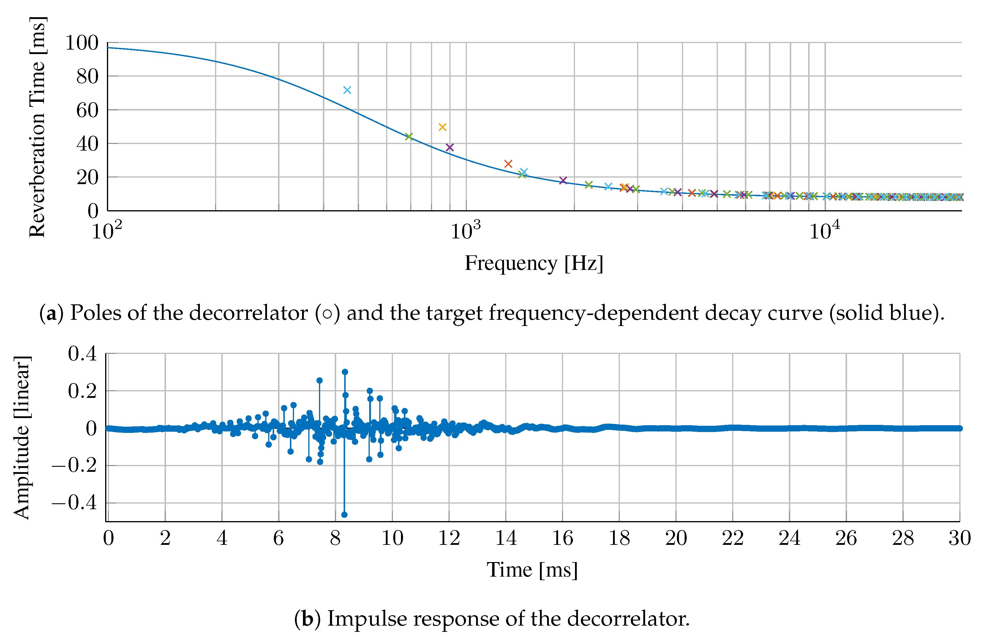
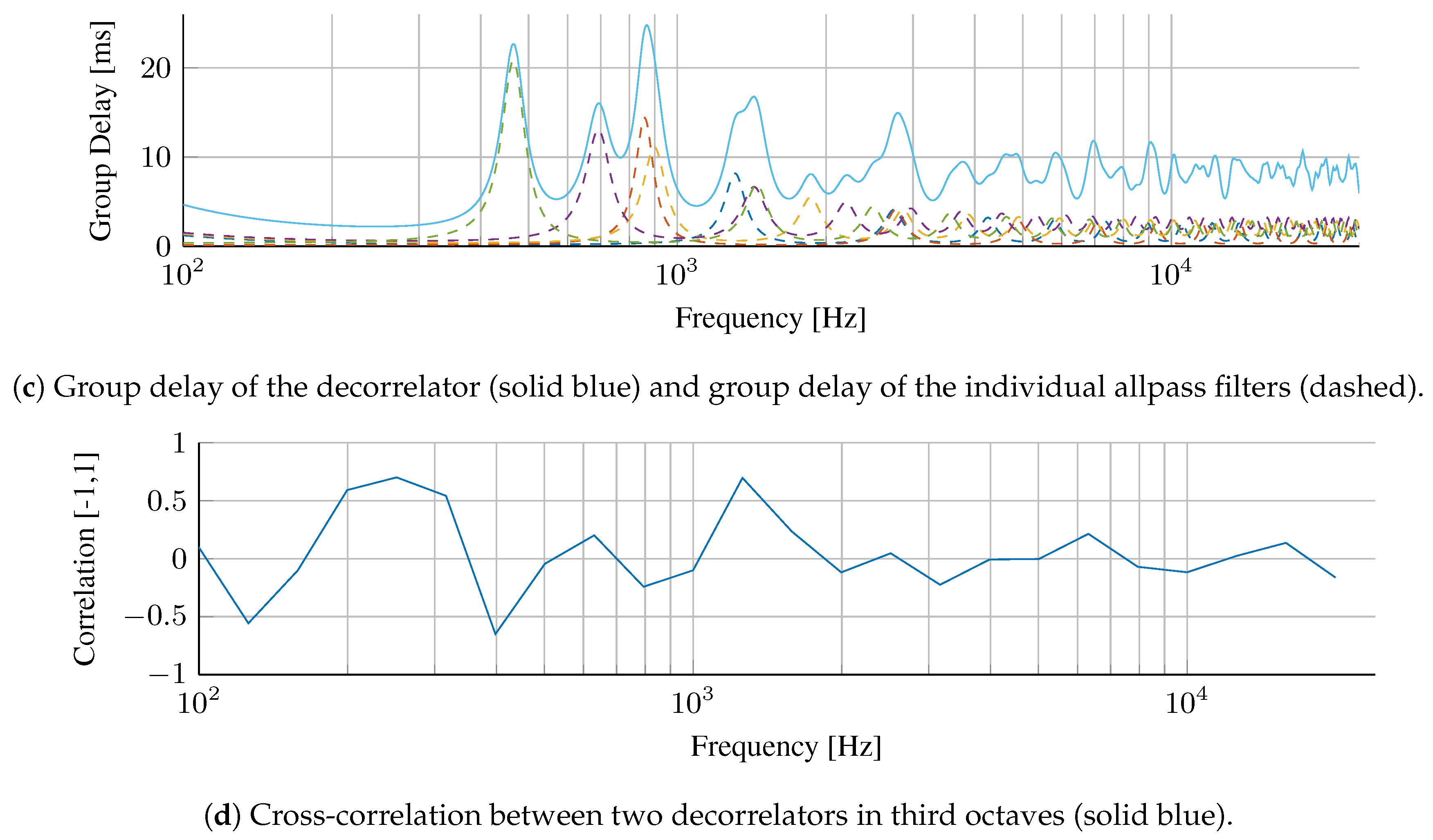
4. Application in Decorrelation

Kendall introduced decorrelation filters to widen the spatial image of sound sources [14]. The decorrelators should ideally break up the phase relationships in a signal while leaving the magnitude response unaltered. Thus, allpass filters are the natural choice for decorrelators. For audio applications, the time-smearing caused by the phase alteration shall be limited to avoid degradation of transient sounds. The acceptable frequency-dependent group delay was found to be 60 ms at low frequencies and 10–20 ms in the high frequencies [22]. Alternative decorrelator designs include velvet noise decorrelators [23,24] and frequency-domain reverberators [25].
The group delay of a single Schroeder allpass filter has a comb-like shape (see Figure 7d). Multiple of such comb characteristics can be superposed to achieve a less regular structure. This, in turn, is equivalent to a series of Schroeder allpasses with different delays m i and gains g i ( z ) , but with the same target decay curve, | g i ( e ı ω ) | 1 / m i . The delays m i of the i t h allpass filter are 42 , 60 , 86 , 91 , 120 samples for i = 1 , , 5 . A second decorrelation filter is designed with delays 41 , 93 , 94 , 134 , 144 . In the following, the sample rate is 48 kHz and we study a series combination of five allpass filters. For ease of interpretation, the decorrelator pole magnitudes are given in terms of reverberation time, i.e., the time required for the corresponding exponential to decay by 60 dB. The gains g i ( z ) are realized by a first-order shelving filter [26] such that each Schroeder allpass filter has 7 non-zero coefficients. In total, the proposed decorrelator has only 35 non-zero coefficients, which is less than 1% compared to the decorrelator introduced in [22] and similar to the velvet noise decorrelator in [24].
Figure 8a shows the poles of the proposed decorrelator alongside the target frequency-dependent decay curve. The poles of the individual allpass filters follow the target curve closely with only some deviation for the lowest frequency poles. Figure 8b depicts the corresponding impulse response. In Figure 8c, we present the total group delay of the decorrelator alongside the group delay of the individual allpass filters. The cross-correlation between two decorrelators in each third octave band is shown in Figure 8d. The maximum values are 0.6 for low and mid frequencies and 0.2 for high frequencies, which can be considered sufficiently low for many audio applications. Listening examples of this decorrelator can be found online (https://www.sebastianjiroschlecht.com/publication/Frequency-Dependent-Schroeder-Allpass-Filters/).

5. Conclusions

This paper proposed a novel frequency-dependent Schroeder allpass filter, which is both more flexible in design and computationally efficient. The feedforward/-back gain filter is only required to be stable and dampening. The proposed design is about a factor of three more efficient than the previous filter structures by Gerzon. As an application example, we demonstrated the effectiveness of the proposed filter for signal decorrelation. As future work, other allpass filter applications such as artificial reverberation and dispersive systems may be studied. Furthermore, it remains to be shown whether a similarly effective design is possible for allpass feedback delay networks, both for single and multiple input and output (SISO and MIMO) configurations.

Funding

This research received no external funding.

Conflicts of Interest

The author declares no conflict of interest.

References

  1. Schroeder, M.R.; Logan, B.F. “Colorless” artificial reverberation. IRE Trans. Audio 1961, AU-9, 209–214. [Google Scholar] [CrossRef]
  2. Välimäki, V.; Parker, J.D.; Savioja, L.; Smith, J.O., III; Abel, J.S. Fifty years of artificial reverberation. IEEE/ACM Trans. Audio Speech Lang. Process. 2012, 20, 1421–1448. [Google Scholar] [CrossRef]
  3. Abel, J.S.; Smith, J.O., III. Robust Design of Very High-Order Allpass Dispersion Filters. In Proceedings of the International Conference Digital Audio Effects (DAFx), Montreal, QC, Canada, 18–20 September 2006; pp. 13–18. [Google Scholar]
  4. Gardner, W.G. A real-time multichannel room simulator. J. Acoust. Soc. Am. 1992, 92, 1–23. [Google Scholar] [CrossRef]
  5. Gerzon, M.A. Unitary (energy-preserving) multichannel networks with feedback. Electron. Lett. 1976, 12, 278–279. [Google Scholar] [CrossRef]
  6. Poletti, M.A. A Unitary Reverberator For Reduced Colouration In Assisted Reverberation Systems. In Proceedings of the INTER-NOISE and NOISE-CON, Newport Beach, CA, USA, 10–12 July 1995; Volume 5, pp. 1223–1232. [Google Scholar]
  7. Schroeder, M.R. Natural Sounding Artificial Reverberation. J. Audio Eng. Soc. 1962, 10, 219–223. [Google Scholar]
  8. Moorer, J.A. About this reverberation business. Comput. Music J. 1979, 3, 13–17. [Google Scholar] [CrossRef]
  9. Väänänen, R.; Välimäki, V.; Huopaniemi, J.; Karjalainen, M. Efficient and Parametric Reverberator for Room Acoustics Modeling. In Proceedings of the International Computer Music Conference, Thessaloniki, Greece, 25–30 September 1997; pp. 200–203. [Google Scholar]
  10. Dattorro, J. Effect Design, Part 1: Reverberator and Other Filters. J. Audio Eng. Soc. 1997, 45, 660–684. [Google Scholar]
  11. Dahl, L.; Jot, J.M. A Reverberator based on Absorbent All-pass Filters. In Proceedings of the International Conference Digital Audio Effects (DAFx), Verona, Italy, 7–9 December 2000; pp. 1–6. [Google Scholar]
  12. Lokki, T.; Hiipakka, J. A time-variant reverberation algorithm for reverberation enhancement systems. In Proceedings of the International Conference Digital Audio Effects (DAFx), Limerick, Ireland, 6–8 December 2001; pp. 28–32. [Google Scholar]
  13. Schlecht, S.J.; Habets, E.A.P. Time-varying feedback matrices in feedback delay networks and their application in artificial reverberation. J. Acoust. Soc. Am. 2015, 138, 1389–1398. [Google Scholar] [CrossRef] [Green Version]
  14. Kendall, G.S. The Decorrelation of Audio Signals and Its Impact on Spatial Imagery. Comput. Music J. 1995, 19, 71. [Google Scholar] [CrossRef]
  15. Boueri, M.; Kyriakakis, C. Audio Signal Decorrelation Based on a Critical Band Approach. In Proceedings of the Audio Engineering Society Convention 117, San Francisco, CA, USA, 28–31 October 2004. [Google Scholar]
  16. Kermit-Canfield, E.; Abel, J.S. Signal Decorrelation Using Perceptually Informed Allpass Filters. In Proceedings of the International Conference Digital Audio Effects (DAFx), Brno, Czech Republic, 5–9 September 2016; pp. 225–231. [Google Scholar]
  17. Canfield-Dafilou, E.K.; Abel, J.S. A Group Delay-Based Method for Signal Decorrelation. In Proceedings of the Audio Engineering Society Convention 144, Milan, Italy, 23–26 May 2018. [Google Scholar]
  18. Poletti, M.A. The Stability Of Multichannel Sound Systems With Frequency Shifting. J. Acoust. Soc. Am. 2004, 116, 853–871. [Google Scholar] [CrossRef]
  19. Schlecht, S.J.; Habets, E.A.P. The stability of multichannel sound systems with time-varying mixing matrices. J. Acoust. Soc. Am. 2016, 140, 601–609. [Google Scholar] [CrossRef]
  20. Välimäki, V.; Parker, J.D.; Abel, J.S. Parametric Spring Reverberation Effect. J. Audio Eng. Soc. 2010, 58, 547–562. [Google Scholar]
  21. Jot, J.M.; Chaigne, A. Digital delay networks for designing artificial reverberators. In Proceedings of the Audio Engineering Society Convention, Paris, France, 19–22 February 1991; pp. 1–12. [Google Scholar]
  22. Abel, J.S.; Canfield-Dafilou, E.K. Dispersive Delay and Comb Filters Using a Modal Structure. IEEE Signal Process. Lett. 2019, 26, 1748–1752. [Google Scholar] [CrossRef]
  23. Alary, B.; Politis, A.; Välimäki, V. Velvet-Noise Decorrelator. In Proceedings of the International Conference Digital Audio Effects (DAFx), Edinburgh, UK, 5–9 September 2017; pp. 405–411. [Google Scholar]
  24. Schlecht, S.J.; Alary, B.; Välimäki, V.; Habets, E.A.P. Optimized velvet-noise decorrelator. In Proceedings of the International Conference Digital Audio Effects (DAFx), Aveiro, Portugal, 4–8 September 2018; pp. 1–8. [Google Scholar]
  25. Vilkamo, J.; Neugebauer, B.; Plogsties, J. Sparse Frequency-Domain Reverberator. J. Audio Eng. Soc. 2012, 59, 936–943. [Google Scholar]
  26. Välimäki, V.; Reiss, J.D. All About Audio Equalization: Solutions and Frontiers. Appl. Sci. 2016, 6, 129. [Google Scholar] [CrossRef] [Green Version]
Figure 1. Classic Schroeder allpass filter [1], i.e., a feedforward–feedback delay filter.
Applsci 10 00187 g001
Figure 2. Gerzon’s allpass filter with feedforward/-back gain g ( z ) [5].
Applsci 10 00187 g002
Figure 3. Dahl and Jot’s allpass filter with an additional lowpass filter c ( z ) [11].
Applsci 10 00187 g003
Figure 4. Numerical example of a Dahl absorbent allpass filter. (a) Poles and zeros of the gain H Dahl ( z ) (×/⚬) and proportional magnitude response | c ( e ı w ) | / d e l a y (solid red). (b) Magnitude response of | H Dahl ( z ) | .
Applsci 10 00187 g004
Figure 5. Proposed frequency-dependent allpass for an IIR gain g ( z ) = b ( z ) a ( z ) .
Applsci 10 00187 g005
Figure 6. Proposed frequency-dependent allpass for FIR gain g ( z ) = b ( z ) .
Applsci 10 00187 g006
Figure 7. Numerical example of a frequency-dependent Schroeder allpass filter. (a) Poles and zeros of the gain g ( z ) (×/⚬) and magnitude response | g ( e ı w ) | (solid red); (b) Poles and zeros of the Schroeder allpass (×/⚬) and magnitude response | g ( e ı w ) | 1 / m (solid red); (c) Impulse response of the Schroeder allpass; (d) Group delay of the Schroeder allpass.
Applsci 10 00187 g007
Figure 8. Decorrelator based on the proposed frequency-dependent Schroeder allpass.
Applsci 10 00187 g008aApplsci 10 00187 g008b

