Article

Wettability of CNW/ITO Micro Structure for Modification of Surface Hydrophilicity

College of Information Technology and Department of Electrical Engineering, Hanbat National University, 125 Dongseo-daero, Yuseong-gu, Daejeon 34158, Korea
*
Author to whom correspondence should be addressed.
Appl. Sci. 2020, 10(1), 142; https://doi.org/10.3390/app10010142
Submission received: 29 November 2019 / Revised: 17 December 2019 / Accepted: 20 December 2019 / Published: 23 December 2019
(This article belongs to the Special Issue Carbon Nanostructures: Fabrication and Applications)

Abstract

:
Although the carbon nanowall is a remarkable material in various fields, it generally shows near hydrophobicity. For modification of hydrophilicity, various modification techniques have been utilized, however, most of the techniques adopted a modification to carbon oxide by chemical processing and plasma treatment, which induce carbon lattice defects, causing the decline of the carbon nanowall quality. While we introduce an eco-friendly modification technique that causes non-defect of carbon lattice and maintains intrinsic carbon nanowall properties by depositing ITO on pristine-carbon nanowall for inducing hydrophilicity. The morphology of carbon nanowall (CNW)/ indium tin oxide (ITO) microstructure was examined by FE-SEM, and the functional group and oxygen components of ITO were investigated by analyzing XPS. The contact angles were measured for wettability analysis according to the surface thickness of ITO.

1. Introduction

Carbon nanomaterials such as graphene, carbon nanotube (CNT), carbon nanosheet (CNS), and carbon nanowall (CNW) have a nano-micro thin scale and structure, causing flexibility as well as remarkable electric, mechanic, and thermal properties. Hence, carbon nanomaterials have been spotlighted as an advanced crucial material on application devices [1,2,3,4].
As time passes, the application fields of carbon nanomaterials are being expanded and widened. Recently, it is attracting attention for its utilization on filter devices for desalination, medical devices in blood, and sensor devices for the detection of liquids. Furthermore, it is expected that carbon nanomaterials-based devices will be utilized in water, ocean, and oil to detect variations of them [5,6,7]. For the application of carbon nanomaterials on advanced devices related to liquids, it is crucial to interact between carbon nanomaterials and liquids, and thus the surface wettability of the carbon material is the key point. The wettability is one of the surface properties which is settled by molecules and the area distributed at the boundary surface of carbon nanomaterials and liquids with a range from nm to um, and alteration of the molecules-area with a surface structure of carbon nanomaterials is efficiently able to affect wettability. As methods for change of wettability, various techniques modifying the surface structure and components have been employed [8,9,10,11]. In this regard, and compared with the surface structure of carbon nanomaterials mentioned above, graphene and CNT are horizontal against the substrate. It is difficult to modify surface structure due to a thin carbon layer less than 2 nm. Hence, surface componential modification techniques are suitable for graphene and CNT [12]. The typical method employed for modification of the surface component is chemical processing, which enables indisputable surface modification, however, it induces a non-eco-friendly environmental impact [13]. Additonally, the CNW stands perpendicular to the substrates with a nano-micro structure. The CNW named as vertical graphene, free-standing graphene, and graphene nanowall includes a lot of graphene layer-based walls capable of growing up to 2.33 μm (from the last experiment), which affects the laplace pressure (PL) and enables it to change the wettability [14,15,16]. Moreover, the CNW, which is outstanding on binding capacity, stable chemistry, and reactivity with various materials, is simple to surface structure change through evaporation or sputtering.
The CVD-based carbon nanowalls are mainly non-polar and are near hydrophobicity due to the absence of oxygen functional groups on the surface. The surface modification is essential because these surface properties are difficult to apply to devices that require contact with liquids. The hummer’s method and oxygen plasma are mainly used to modify the surface, both of which destroy the natural properties of the carbon materials. Therefore, we report research and results on surface structure modification-based manipulation of wettability using ITO (indium tin oxide). ITO, one of the TCO (transparent conductive oxide), was utilized to vary the surface structure and area of pristine-CNW as a starting material. Then, we investigated wettability change based on the influence from the ITO-structure deposited on pristine-CNW and the O-H group included in In2O3 and SnO2 on wettability.

2. Experimental

2.1. Materials and Modification

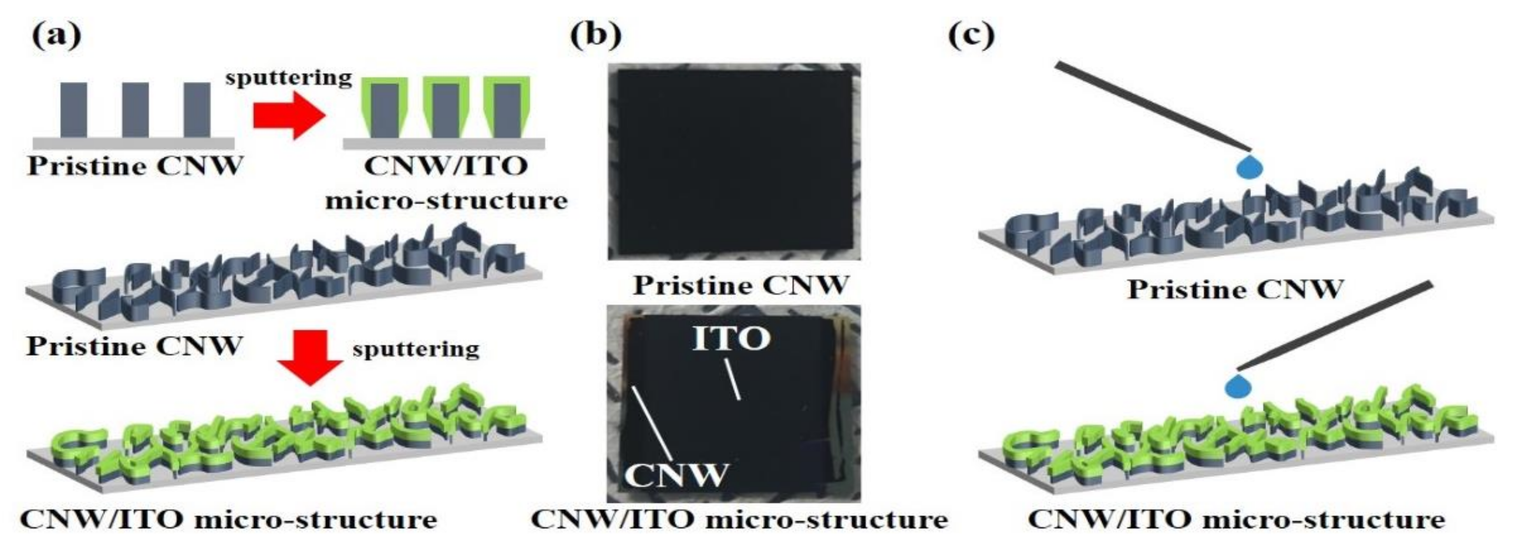
Si substrate oriented-111 was prepared through ultrasonic cleaning in acetone, methanol, and deionized (DI) pure water for 10 min, respectively. The cleaned Si substrate was then dried by nitrogen. Then, for synthesis of pristine-CNW on the Si substrate, microwave plasma-enhanced chemical vapor deposition (PECVD, Woosin CryoVac, Uiwang, Korea; CVD-R2,) was operated, and the synthesis of pristine-CNW was progressed at 600 °C (heating temperature), fixing 2.5 × 10⁻² torr (working pressure) in the chamber. The starting material, pristine-CNW, was synthesized under 1300 W (microwave power), 10 min (growth time), H2:25 sccm and CH4:55 sccm (reaction gas ratio). To modify the surface structure of pristine-CNW synthesized, ITO nano-particles were sputtered onto pristine-CNW by an rf magnetron sputtering system (ITS, PG600A_600W) for 15 min, 30 min, and 45 min, injecting argon gas of 50 sccm with RF power of 100 W. The related contents were illustrated in Figure 1a.

2.2. Analysis and Measurement

For the investigation of morphology and wettability of fabricated CNW/ITO micro-structure, various analyses and measurements were performed. The high resolution-field emission scanning electron microscope (HR-FESEM, Hitachi high-technologies, Seoul, Korea; S-4800) was employed under 10 kV acceleration voltage to examine the surface of pristine-CNW and CNW/ITO micro-structure. The X-ray diffraction (XRD, Rigaku Corp., Tokyo, Japan; D/MAX-2500) and Raman spectroscopy (NOST, FEX MRA10) analysis were employed to examine the crystallization of ITO and defects in carbon lattice. We carried out an X-ray photoelectron spectroscopy (XPS, PHI 5000 VersaProbe) analysis for ITO thickness-dependence componential variation. The wettability of the CNW/ITO micro-structure was determined through the contact angle (CA, SEO Inspection of Phoenix MT), as shown in Figure 1b.

3. Results and Discussion

Figure 2 shows the surface of pristine-CNW (starting material) and CNW/ITO micro-structure (modified CNW). As shown in Figure 2a, typical pristine-CNW was freely grown with graphene layers-based nanosheets on the substrate, which has a thickness of 5~10 nm and height of 1.0~1.3 μm. These nanosheets show a curve and wrinkle-shaped morphology entangled in multiple directions. It is a phenomenon owing to the field-effect induced by plasma and it is one of the representative characteristics. The surfaces of the CNW/ITO micro-structure modified by ITO nano-particles sputtered onto pristine-CNW were observed, corresponding to Figure 2b–d. The wall thickness in the CNW/ITO micro-structure with ITO sputtered for 15 min is 60~80 nm, which shows that it is thicker compared with the pristine-CNW (Figure 2b). In increasing the sputtering time, the wall thickness of CNW/ITO micro-structure became thicker (30 min, 105~120 nm; 45 min, 160~173 nm), respectively (Figure 2c,d). The nano-porous area (yellow circle) reduced as the thickness increased of the CNW/ITO micro-structure. After examining the surface of the pristine-CNW and CNW/ITO micro-structure through FE-SEM, we can suppose that the boundary surface between the water droplet and ITO widens depending on the surface thickness of ITO, which may affect wettability with variations of nano-porous areas.
For wettability on the side of ITO synthesized on pristine-CNW, we conducted a cross-sectional FE-SEM measurement as shown in Figure 3. In the case of pristine-CNW, pillar-shaped carbon nanowalls perpendicularly aligned on Si substrate were identified. Interestingly, innumerable protrusions (yellow quadrangle) were observed by gathering carbon-riched agglomerates on the sides of the carbon nanowalls (right in Figure 3a), and lateral morphological features were examined only in pristine-CNW. When this phenomenon is compared to micro-structures induced by ITO nano-particle sputtered onto pristine-CNW from Figure 3b up to Figure 3d, the distribution area of protrusion on the side of carbon nanowalls significantly reduced, which is indicated by yellow quadrangles in Figure 3b,c. The reduced yellow quadrangles signify that the visually identifiable height of the protrusion area decreased more than on pristine-CNW, since carbon-based protrusions were partially covered with ITO sputtered onto pristine-CNW.
In addition, we must investigate the formation of ITO on the top of pristine-CNW. The specimens, ITO sputtered onto pristine-CNW, appeared to have a thickness of around 1.1~1.5 μm. It can be assumed that indium tin oxide was deposited at nano-scale thickness compared to pristine-CNW (1.0~1.3 μm). For precise thickness analysis, we deposited indium tin oxide on the Si substrate, and its thickness was within 150 nm as shown in Figure 3e, which means ITO sputtered onto pristine-CNW and Si substrate/ITO have a similar thickness. Additionally, we noticed that columnar-shaped grain boundaries (blue quadrangles) were distinctly generated at indium tin oxide on top of CNW. It suggests that as the similar grain boundaries were examined in the reference indium tin oxide deposited under the same conditions by sputtering, it was thoroughly deposited on pristine-CNW.
To figure out the crystallization of ITO and defects of CNW based on carbon disorder with alignment, XRD (X-ray diffraction) and Raman spectra were employed. Figure 4a shows the crystallization peaks of ITO by different sputtering times. The polycrystalline with various peaks corresponding to the planes (222), (400), (440), (622) observed in bixbyite-structure were commonly identified [17]. When sputtering time increases up to 30 min, a sharp (222) peak showed extraordinary crystallization. On the other hand, the XRD pattern of 45 min offered a relatively improved (400) peak than the (222) peak, which implies that the (222) plane was the preferred orientation. Figure 4b exhibits the Raman spectra of the pristine-CNW and CNW/ITO micro-structure. To the best of our knowledge, D (1350 cm−1), G (1580 cm−1), and 2D (2700 cm−1) are the common band of carbon materials, and a high D band and D′ band (shoulder band) is a unique band that can only be found in defected graphite [18,19,20]. In the Raman spectra of the CNW/ITO micro-structure from Figure 4b, it shows a low ID/IG ratio (1.71) with a low D band than pristine-CNW. As the D′ band is revealed at the graphene edge and sp3-hybridization, the conspicuous change of D′ band is an interesting phenomenon [21]. This phenomenon may signify that the opened zigzag shaped-graphene edge was transformed to a closed round edge with a stable structure by ITO nano-particles sputtered. The detailed figure of a reduced D′ band is illustrated in Figure 4c. Additionally, we know that two specimens consist of multi-layered graphene through I2D/IG ratio.
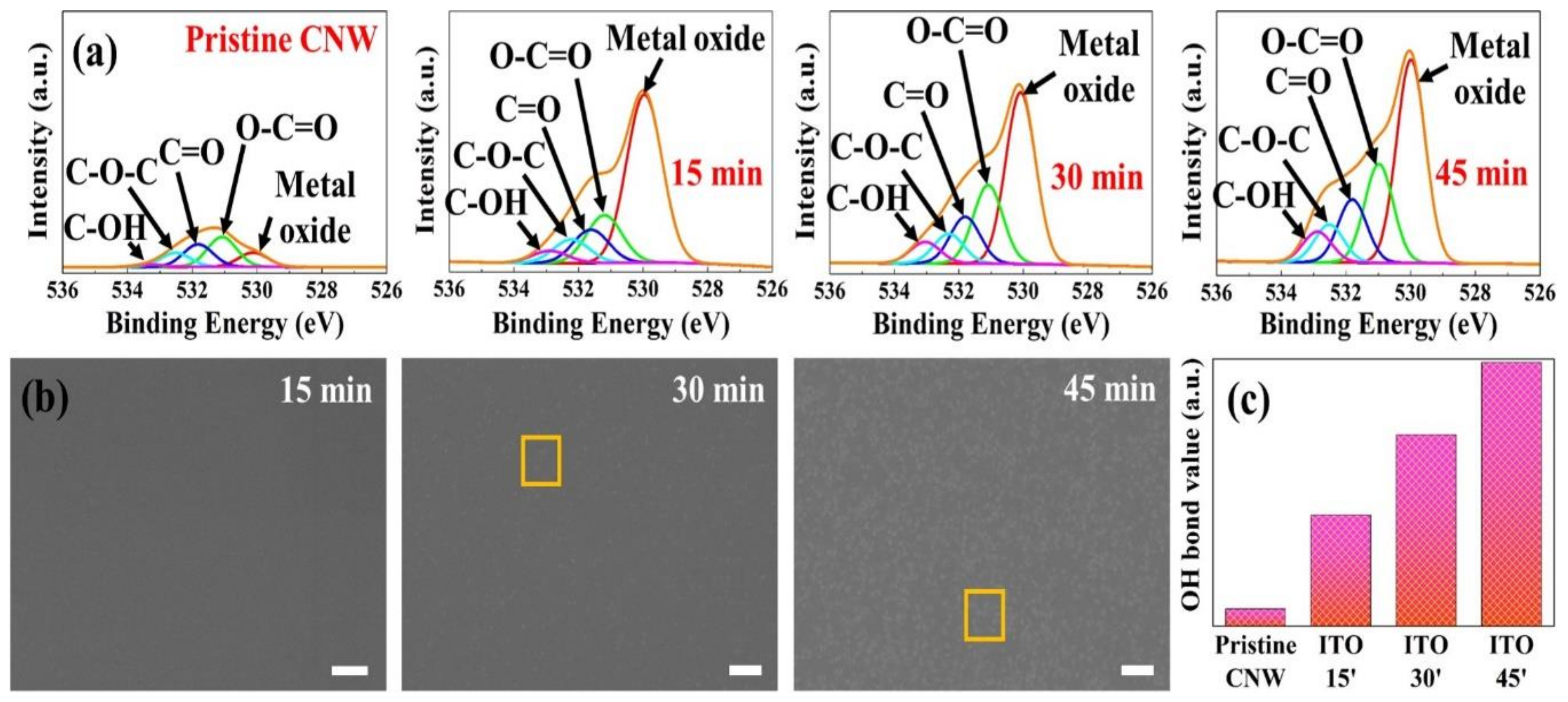
Although the wettability is affected by the variations of surface area and structure by the modified CNW/ITO micro-structure, components and functional groups on the surface enable it to have an effect on wettability because the fraction contacted with the water droplets in the CNW/ITO micro-structure is the ITO surface. Hence, X-ray photoelectron spectra analysis was operated to observe chemical variations including the components and functional groups on the ITO surface. The variation in chemical components from XPS results is briefly exhibited in Table 1. In the Table 1, the variation of carbon and oxygen were perceptible, and it is noted that the top of the carbon nanowall was scraped off by indium tin oxide nano-particles sputtered. The cause of the reduction in components of In/Sn may be due to the accumulated sputtering time. Generally, if the sputtering time is prolonged, the particles composing a thin film may be thrown out by sputtered particles. In this case, In (450 eV) and Sn (490 eV) having a relatively lower binding energy than oxygen (530 eV) may bounce off. It is assumed that this resulted in a reduction of In/Sn. The functional groups that contributed to wettability are contained in various chemical groups such as epoxy, carbonyl (C=O), hydroxyl (C-OH), and carboxyl (COOH). Especially the hydroxyl groups that constitute hydrogen bonds with strong bonding energy are a highly important key group. Figure 5a shows the chemical composition of ITO sputtered onto pristine CNW as narrow results of O 1s peak by X-ray photoelectron spectroscopy. This result presented various chemical compositions which were deconvoluted into five peaks, corresponding to a metal oxide bond at 530.1–530.2 eV, O-C=O (carboxyl) bond at 531.1 eV, C=O (carbonyl) group at 531.8–531.9 eV, O-C-O (epoxy) group at 532.5 eV, and C-OH (hydroxyl) bond at 533.1–533.7 eV, respectively. In the case of the pristine-CNW, very low peaks were identified, implying surface non-activation without a functional group. It is noted that a few peaks such as C=O bond and O-C=O bond may appear by natural oxidation in the air. In Figure 5a, the specimens sputtered with ITO commonly exhibit a metal oxide peak around 530.1 eV that is derived from metal oxides. The metal oxide peak reveals an increasing tendency with sputtering time, and it may be because oxygen in the air is adsorbed [22]. The various oxygen-related groups dramatically increased compared to pristine-CNW. We suppose that it might be affected by surface crystallization (orange quadrangle) as shown in FE-SEM (Figure 5b). In sputtering time of 15 min, surface crystallization was unexamined. While the ITO surface sputtered for 45 min onto pristine-CNW significantly exhibited surface crystallization. The OH bond around 533.3 eV changed by sputtering times with 15 min, 30 min, and 45 min was proportional to the sputtering time. It is summarized in Figure 5c, presenting a remarkably stepped plot than in pristine-CNW. Besides the structural modification identified by FE-SEM (Figure 2 and Figure 3), we can infer that it may occur a variation in wettability by a chemical composition change.
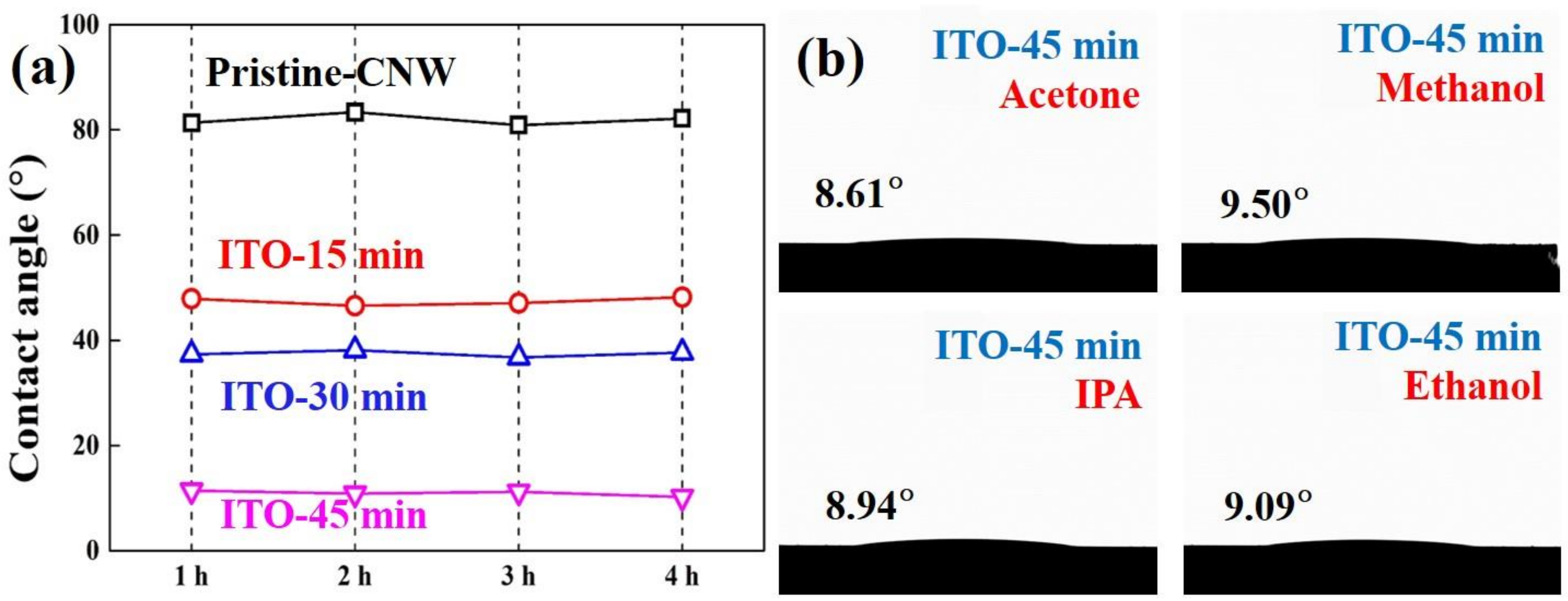
We conducted a surface-structure analysis through FE-SEM and chemical composition-based surface analysis with XPS followed by a wettability analysis for hydrophobicity and hydrophilicity using a water droplet method. As shown in Figure 6a, the pristine-CNW exhibits near hydrophobicity (low wettability, CA > 80°) as a high repellency towards water droplets. It is probably because the CNW composed of pure carbon is aromatic and non-polar causing difficulty with water interaction. Additionally, it may be contributed by the non-composition of oxygen-related groups on the pristine-CNW surface, and the air area located between the carbon nanowalls (pillars) hinders contact with the water droplet and substrate. The thin and narrow surface area at the top edge of the CNW with a nano-porous area results in low surface energy, which can cause almost hydrophobicity. While the CNW/ITO micro-structure by ITO sputtered onto pristine-CNW was investigated by showing hydrophilicity (high wettability, CAs < 50°) compared with pristine-CNW, which is similar to an oxidized surface. This hydrophilicity can be explained by a high surface energy proportional to the ITO surface area and reduced air area. Firstly, the lowest CA (11.23°) was obviously identified at a sputtering time of 45 min that means the widest ITO surface area in all specimens, being assumed the highest surface energy. In addition, the increase in surface energy caused by plasma in the sputtering step may be contributed to the reason for hydrophilicity. The plasma ion exhibit zig-zag movement in terms of nanowalls, is where the plasma-ion kinetic energy is reduced and absorbed [23]. As a result, the surface energy at the bottom is inevitably low because plasma ions are difficult to move to the bottom by its unique structure (Figure 6c). Hence, the surface-energy activation area in the CNW having a pillar-columnar structure is relatively higher at the top edge more than at the bottom. It is also associated with the Laplace pressure (PL) with surface energy, which occurred a low surface energy direction from high surface energy. In Figure 6d (left), PL is induced with an upward direction, and it created meniscus by forming a boundary surface with downward intrinsic pressure (Pi), causing hydrophobicity [24]. In the case of CNW/ITO micro-structure, surface energy in proportion to surface area is increased by ITO deposited on CNW. It showed hydrophilicity because of the overlap of downward PL and Pi (Figure 6d (right)). Secondly, the sputtered indium tin oxide nano-particles can reduce the air area between the carbon nanowalls (pillars), which induces hydrophilicity shown by causing weakened repellency than hydrophobicity in interaction with water droplets (Figure 6e (right)). In the componential aspect, the high hydrophilicity was determined with an increase of OH bond and other chemical bonds related with the oxygen on the ITO surface. As shown in Figure 6f, the oxygen of the ITO surface induces a hydrogen bond with the hydrogen composition in the water droplet. This is consistent with the expected result by X-ray photoelectron spectra. Other wettability tests were carried out in order to evaluate the stability over time of the wetting properties of all samples and the wettability of the CNW/ITO micro-structure versus different solvents. Thus, the values of the contact angles are constant for all specimens (Figure 7a). The wetting behavior of the micro-structure with ITO sputtered for 45 min versus 4-typed organic solvents (acetone, methanol, isopropyl alcohol (IPA), and ethanol) showed outstanding wettability (CAs < 10°) (Figure 7b).

4. Conclusions

Herein, we introduced results based on the wettability of the CNW/ITO micro-structure through this article. (i) The morphology of pristine-CNW and CNW/ITO micro-structure were characterized by SEM, and the wall thickness of the CNW/ITO micro-structure by ITO became thicker compared with pristine-CNW. (ii) The X-ray diffraction and Raman spectroscopy analysis were employed for the crystallization of ITO sputtered and defects with disordered carbon lattice in the CNW. The (222) plane was determined as the preferred orientation in the X-ray diffractions result. In Raman spectra, a reduced ID/IG ratio and D′ band were observed. (iii) The X-ray photoelectron spectra were performed for the investigation of the oxygen-functional group on the surface of the CNW/ITO micro-structure and showed an increase of oxygen-related chemical composition is proportional to the surface area of ITO. (iv) In the wettability results of CNW/ITO micro-structure by measuring CAs, pristine-CNW showed almost hydrophobicity (CAs > 80°). In contrast, CNW/ITO micro-structure exhibited further hydrophilicity (CAs < 80°). In addition, wettability of the CNW/ITO micro-structure maintained hydrophilicity for 4 h in an experiment for stability, and the wetting feature of CNW/ITO micro-structure by ITO sputtered for 45 min with organic solvents (acetone, methanol, isopropyl alcohol (IPA), and ethanol) appeared to have exceptional hydrophilicity (CAs < 10°). We expect that our experiment results adopted an eco-friendly surface structure modification which will have utilization and application in the field of surface coating and modification.

Author Contributions

Conceptualization, S.K. and W.C.; methodology, S.K., H.C.; formal analysis, S.K. and H.C.; software, S.K.; writing, S.K.; supervision, H.K. All authors have read and agreed to the published version of the manuscript.

Funding

This research received no external funding.

Acknowledgments

This work was supported by the Korea Institute of Energy Technology Evaluation and Planning (KETEP) and the Ministry of Trade, Industry & Energy (MOTIE) of the Republic of Korea (No. 20184030201900) and was also supported by Korea Electric Power Corporation [Grant number: R18XA06-25].

Conflicts of Interest

The authors declare no conflict of interest.

References

  1. He, J.; Chen, Y.; Lv, W.; Wen, K.; Li, P.; Qi, F.; Wang, Z.; Zhang, W.; Li, Y.; Qin, W.; et al. Highly-flexible 3D Li2S/graphene cathode for high-performance lithium sulfur batteries. J. Power Sources 2016, 327, 474–480. [Google Scholar] [CrossRef]
  2. Sun, G.; An, J.; Chua, C.K.; Pang, G.; Zhang, J.; Chen, P. Layer-by-layer printing of laminated graphene-based interdigitated microelectrodes for flexible planar micro-supercapacitors. Electrochem. Commun. 2015, 51, 33–36. [Google Scholar] [CrossRef]
  3. Moghadam, A.D.; Omrani, E.; Menezes, P.L.; Rohatgi, P.K. Mechanical and tribological properties of self-lubricating metal matrix nanocomposites reinforced by carbon nanotubes (CNTs) and graphene. Compos. Part B Eng. 2015, 77, 402–420. [Google Scholar] [CrossRef]
  4. Yang, Z.; Ren, J.; Zhang, Z.; Chen, X.; Guan, G.; Qiu, L.; Zhang, Y.; Peng, H. Recent Advancement of Nanostructured Carbon for Energy Applications. Chem. Rev. 2015, 115, 5159–5223. [Google Scholar] [CrossRef] [PubMed]
  5. Kazemi, A.S.; Hosseini, S.M.; Abdi, Y. Large total area membrane of suspended single layer graphene for water desalination. Desalination 2019, 451, 160–171. [Google Scholar] [CrossRef]
  6. Huang, H.H.; Joshi, R.K.; Silva, K.K.H.D.; Badam, R.; Yoshimura, M. Fabrication of reduced graphene oxide membranes for water desalination. J. Membr. Sci. 2019, 572, 12–19. [Google Scholar] [CrossRef]
  7. Pattnaik, S.; Swain, K.; Lin, Z. Graphene and graphene-based nanocomposites: Biomedical applications and biosafety. J. Mater. Chem. B 2016, 48, 7813–7831. [Google Scholar] [CrossRef]
  8. Yang, Z.; Tian, Y.L.; Yang, C.J.; Wang, F.J.; Liu, X.P. Modification of wetting property of Inconel 718 surface by nanosecond laser texturing. Appl. Surf. Sci. 2017, 414, 313–324. [Google Scholar] [CrossRef] [Green Version]
  9. Xiaorui, S.; Zheng, B.; Jing, K. Wettability of vertically-oriented graphenes with different intersheet distances. RSC Adv. 2017, 7, 2667–2675. [Google Scholar]
  10. Hitoshi, W.; Hiroki, K.; Yukihiro, O. Carbon nanowall scaffold to control culturing of cervical cancer cells. Appl. Phys. Lett. 2014, 105, 244105. [Google Scholar]
  11. Sorin, V.; Daniela, I.M.; Gheorghe, D. Post-synthesis Carbon Nanowalls Transformation under Hydrogen, Oxygen, Nitrogen, Tetrafluoroethane and Sulfur Hexafluoride Plasma Treatments. Plasma Processes Polym. 2012, 9, 363–370. [Google Scholar]
  12. Shearer, C.J.; Slattery, A.D.; Stapleton, A.J.; Shapter, J.G.; Gibson, C.T. Accurate thickness measurement of graphene. Nanotechnology 2016, 27, 125704. [Google Scholar] [CrossRef] [PubMed]
  13. Ravi, R.; Iqbal, S.; Ghosal, A.; Ahmad, S. Novel mesoporous trimetallic strontium magnesium ferrite (Sr0.3Mg0.7Fe2O4) nanocubes: A selective and recoverable magnetic nanoadsorbent for Congo red. J. Alloys Compd. 2019, 791, 336–347. [Google Scholar] [CrossRef]
  14. Davami, K.; Cortes, J.; Hong, N.; Bargatin, I. Vertical graphene sheets as a lightweight light absorber. Mater. Res. Bull. 2016, 74, 226–233. [Google Scholar] [CrossRef]
  15. Maruyama, J.; Maruyama, S.; Fukuhara, T.; Chashiro, E.; Uyama, H. Ordered mesoporous structure by graphitized carbon nanowall assembly. Carbon 2018, 126, 452–455. [Google Scholar] [CrossRef]
  16. Zhao, L.; Zhao, J.; Liu, Y.; Guo, Y.; Zhang, L.; Chen, Z.; Zhang, H.; Zhang, Z. Continuously Tunable Wettability by Using Surface Patterned Shape Memory Polymers with Giant Deformability. Small 2016, 12, 3327–3333. [Google Scholar] [CrossRef]
  17. Lee, S.; Jung, J.; Lee, M.; Chang, J. An Aqueous Ammonia Sensor Based on Printed Indium Tin Oxide Layer. Sens. Mater. 2017, 29, 57–63. [Google Scholar]
  18. Khanis, N.H.; Ritikos, R.; Chiu, W.S.; Haw, C.Y.; Rashid, N.M.A.; Chia, M.Y.; Khiew, P.S.; Rahman, S.A. SnO2 Nanoparticles Decorated 2D wavy Hierarchical Carbon Nanowalls with Enhanced Photoelectrochemical Performance. J. Nanomater. 2017, 2017, 4315905. [Google Scholar] [CrossRef] [Green Version]
  19. Casallas-Caicedo, F.M.; Vera-Lopez, E.; Agarwal, A.; Drozd, V.; Durigin, A.; Wang, C. Effect of exfoliation method on graphite oxide. A comparison between exfoliation by ball milling and sonication in different media. J. Phys. Conf. Ser. 2019, 1386, 012016. [Google Scholar] [CrossRef]
  20. Ferrari, A.C.; Basko, D.M. Raman spectroscopy as a versatile tool for studying the properties of graphene. Nat. Nanotechnol. 2013, 8, 235–246. [Google Scholar] [CrossRef] [Green Version]
  21. Yadav, A.; Iost, R.M.; Neubert, T.J.; Baylan, S.; Schmid, T. Selective electrochemical functionalization of the graphene edge. Chem. Sci. 2019, 10, 936–942. [Google Scholar] [CrossRef] [PubMed] [Green Version]
  22. Zhao, Y.; Zhang, D.; Guan, J.; Liu, F.; Liang, P.; Cheng, C.; Zhao, J. Interaction Mechanism between Zn and Passivated Stainless Steel. Int. J. Electrochem. Sci. 2019, 14, 301–314. [Google Scholar] [CrossRef]
  23. Mozetic, M.; Vesel, A.; Stoica, S.D.; Vizireanu, S.; Dinescu, G.; Zaplotnik, R. Oxygen atom loss coefficient of carbon nanowalls. Appl. Surf. Sci. 2015, 333, 207–213. [Google Scholar] [CrossRef]
  24. Han, H.; Lee, J.S.; Kim, H.; Shin, S.; Lee, J.; Kim, J.; Hou, X.; Cho, S.W.; Seo, J.; Lee, T. Single-Droplet Multiplex Bioassay on a Robust and Stretchable Extreme Wetting Substrate through Vacuum-Based Droplet Manipulation. ACS Nano 2018, 12, 932–941. [Google Scholar] [CrossRef] [PubMed]
Figure 1. Schematic of the fabrication of carbon nanowall (CNW)/ indium tin oxide (ITO) micro-structure and wettability analysis method: (a) modification of pristine-CNW for CNW/ITO micro-structure; (b) the optical photographs of pristine-CNW and CNW/ITO micro-structure; (c) method in wettability analysis using a water droplet.
Applsci 10 00142 g001
Figure 2. Surface FE-SEM image of pristine-CNW and CNW/ITO micro-structure: (a) pristine-CNW; CNW/ITO micro-structure by ITO nano-particles sputtered for (b) 15 min; (c) 30 min; (d) 45 min.
Applsci 10 00142 g002
Figure 3. Cross-sectional FE-SEM image of CNW/ITO micro-structure: (a) pristine-CNW; CNW/ITO micro-structure by ITO nano-particles sputtered for (b) 15 min; (c) 30 min; (d) 45 min; (e) reference ITO thin film sputtered on Si substrate for 15 min.
Applsci 10 00142 g003
Figure 4. X-ray diffraction and Raman spectra: (a) X-ray diffraction of indium tin oxide with sputtering times; (b) Raman spectra of pristine-CNW and CNW/ITO micro-structure; (c) fitted G and D′ band from Raman spectra.
Applsci 10 00142 g004
Figure 5. X-ray photoelectron spectra of pristine-CNW and ITO sputtered onto pristine-CNW with sputtering time: (a) O 1s result in XPS; (b) surface FE-SEM of ITO sputtered onto pristine-CNW; (c) OH bond value of ITO according to sputtering time.
Applsci 10 00142 g005
Figure 6. Wettabiliy of pristine-CNW and CNW/ITO micro-structure and theoretical principles and schematic of wettability: (a) images of the water droplet’s shape and the corresponding water contact angles values for all specimens; (b) optical photographs of the water droplet on the surface of all specimens; (c) schematic of surface energy activation area by plasma-ion movement; (d) theory of Laplace pressure (PL) and wettability; (e) theory of hydrophobicity (pristine- CNW) and hydrophilicity (CNW/ITO micro-structure); (f) componential principle of hydrophilicity of CNW/ITO micro-structure.
Applsci 10 00142 g006
Figure 7. Stability of CNW/ITO micro-structure and wettability of pristine-CNW and CNW/ITO micro-structure in various solvent: (a) variation in time of the contact angle values for all specimens; (b) images of the solvents droplets’ shape and the corresponding contact angles values for the CNW/ITO micro-structure.
Applsci 10 00142 g007
Table 1. The chemical components of all specimens.
Pristine-CNW15 min30 min45 min
Oxygen2.1251.7754.4957.33
Carbon97.8823.422.1720.79
In/Sn-24.8323.3421.88