Abstract
In this paper, an evolutionary multi-objective optimization algorithm named NSGA-II was used to determine the optimum radius for shape memory alloy (SMA) wires employed in conjunction with the lead rubber bearing (LRB), referred to as an SMA-LRB isolator. This algorithm simultaneously minimizes the mid-span displacement and the base shear force. Then, the optimized SMA-LRBs were implemented in a benchmark bridge to reduce excessive displacements. The results obtained from the nonlinear dynamic analysis show that the implemented approach could effectively optimize the SMA-LRBs. These improved smart isolators can noticeably reduce the maximum displacements and residual deformations of the structure; meanwhile, the base shear and deck acceleration remain less than those of the non-isolated benchmark bridge. This isolator can reduce the maximum mid-span displacement of the bridge by up to 61%, and the mid-span residual deformations by up to 100%, compared to an uncontrolled isolated bridge under different ground motions. This optimized passive system was compared with nonlinear dampers, passive SMA dampers, and a negative stiffness device. The results indicate that the optimized SMA-LRB isolators are generally more successful in reducing and recovering displacements than the other controllers.
1. Introduction
Bridges are critical infrastructure and play essential roles in transportation networks. Hence, distinctive design requirements are necessary to provide their safety during earthquakes or other severe loadings. An alternative to traditional design methods is to use structural control techniques to reduce the structural vibrations produced by external forces, such as earthquakes and winds. These methods generally change the stiffness, mass, damping coefficient, and configuration of the structure. Among various control strategies, employing the base isolators is a popular tactic due to its simplicity, high potential in decreasing the seismic demand of the structure, and high energy absorption ability. Moreover, base isolators do not require any external sources to produce forces, so they are economical.
Although the base isolation systems are prevalent, they have several drawbacks. The major one is the occurrence of large inelastic deformations. These deformations may lead to the collision of two adjacent parts or unseating if the minimum required distance is not provided. Additionally, the base isolation system cannot be applied anymore after inelastic deformations, and they should be replaced with new ones. To prevent these failures, researchers suggested using additional dampers in companion with the base isolators for energy dissipation (Makris and Zhang [1], Soneji and Jangid [2], Dicleli [3]). Recently, researchers have employed intelligent materials, such as SMAs, for the aforesaid dampers. These materials are characterized by a high damping capacity, fatigue strength, erosion resistance, and a high level of super-elastic strain. Because of the exceptional characteristics, SMAs have been widely used in civil structures, and their applications include but are not limited to restraining devices, beam–column connections, special braces, reinforcement or pre-stressing bars and strips, energy dissipating elements, and base isolation systems.
In the last two decades, various researchers have focused on SMAs to enhance the seismic performance of base isolators because of their outstanding properties. To improve the seismic performance of bridges, Wilde et al. [4] took advantage of two different systems, including rubber bearings with SMA and rubber bearings with a lead core (LRB) and lateral bracing named an NZ device. By comparing these systems, it was observed that the former system has more damping capacity in comparison with the latter one. Additionally, using SMA, this system was able to recover its deformation. However, the force applied to the base isolator with SMA was three times more than the other one. Choi et al. [5] introduced a new generation of base isolation devices in which SMA wires were wrapped around an elastomeric bearing to control the instability and residual deformations. They utilized this system in a three-span continuous bridge during an earthquake and compared the results with those of the lead core bearing. The findings proved that the rubber bearing with Nitinol shape memory alloy was able to decrease the deck displacements. Also, no residual displacement was observed. Nevertheless, in extensive shear deformations (200%), the Nitinol wire experienced plastic strains, and the device was not able to work successfully anymore. Hedayati Dezfuli and Alam [6] numerically investigated two different configurations of SMA wires in conjunction with elastomeric bearings. They studied the effects of various parameters, such as the shear strain amplitude, SMA type, dimension ratio of the base isolation, and the level of pre-strain of the SMA wires, on the seismic behavior of base isolators. According to their results, the wire diameters should be selected based on the lateral stiffness and equivalent viscous damping to achieve high performances. Hedayati Dezfuli and Alam [7] proposed a constitutive model for SMA-LRBs. They used the superposition method to decouple the effect of SMA wires and LRB. Then, they developed a new algorithm for the SMA wires and combined it with a bilinear kinematic hardening model, which was considered for the LRB. They verified their results by the finite element model, which was validated through experimental tests. Hedayati Dezfuli et al. [8] implemented their proposed constitutive model for simulating the behavior of SMA-LRBs in Opensees software to assess the accuracy of the model. The results showed that the new model could precisely predict the shear hysteretic response of smart SMA-LRBs compared with other existing models. Xiang and Alam [9] used four different retrofitting devices to enhance the seismic performance of an LRB-isolated bridge, including yielding steel cables (YSCs), viscous dampers (VDs), friction dampers (FDs), and super-elastic shape memory alloy cables. The results indicated that the SMA device was better than the other measures regarding its self-centering capability and showed the least residual superstructure displacement. Many other researchers also investigated the application of SMAs in mitigating the seismic response of bridges, including but not limited to Andrawes and DesRoches [10], Ozbulut and Hurlebaus [11], Bhuiyan and Alam [12], Zhu and Qiu [13], Mishra et al. [14], Choi et al. [15], Li and Mao [16], and Wang et al. [17].
Researchers have suggested control devices and applied them to different bridges. For this reason, it was hard to compare their results. To overcome this difficulty, a benchmark highway bridge was developed in two phases. Many researchers have implemented their control devices on phase I of the benchmark bridge, in which the deck of the bridge was rigidly connected to the central pier (Agrawal et al. [18]). Tan and Agrawal [19] presented sample designs for three control systems. Madhekar et al. explored the use of different passive and semi-active devices on the phase I bridge [20,21,22]. Saha et al. also applied passive control devices on this bridge [23,24,25].
Some other research was done on the benchmark bridge in phase II, in which the deck was completely isolated from the central pier (Nagarajaiah et al. [26]). Zhang et al. [27] suggested a damper with SMA for controlling the displacements of the second phase of the benchmark bridge. Also, these researchers studied the effect of the temperature changes on the behavior of SMA and their presented device. They observed that the effect of temperature was negligible, and the suggested device was successful in reducing the displacements and residual deformations. Casciati et al. [28] investigated the seismic performance of a new SMA device in the second phase of the benchmark bridge. Their passive SMA damper considerably reduced the maximum displacement of the base isolator and displacements. However, this system increased the maximum base shear and overturning moment. Recently, Li et al. [29] proposed a novel negative stiffness device (NSD) and a damper system for seismic control of the benchmark bridge in phase II and compared its effectiveness with sample passive and semi-active controllers. In their system, passive fluid dampers were used in parallel to the NSD to alleviate excessive displacement. The results showed that the proposed approach was more successful than the two other systems in the reduction of the base shear and mid-span acceleration. However, the semi-active sample controller was slightly more effective in controlling mid-span displacement and bearing deformation.
In the literature, the effectiveness of SMA isolators in reducing displacements and residual deformations of bridges is widely studied; however, it usually causes an increase in the base shear and the deck acceleration or may not be effective in large shear deformations. Therefore, to address these issues, in this study, the radius of the wire was optimized using a multi-objective non-dominated sorting genetic algorithm (NSGA-II) to minimize the base shear and the mid-span displacement simultaneously. It is also worthwhile to mention that a new ferrous SMA material (i.e., FeNiCoAlTaB) with a large elastic strain was used in SMA-LRBs. The optimized SMA isolators were applied in the benchmark bridge in phase II, and the results were compared with three other passive control methods used for this bridge: Nonlinear dampers, passive SMA dampers, and a new negative stiffness device.
2. Shape Memory Alloys (SMAs)
SMAs are intelligent materials with exceptional properties. SMAs have complex thermo-dynamical behavior, which is related to the various physical processes. The well-known properties of these materials are super-elasticity and the shape memory effect (Paiva and Savi [30]). In terms of their super-elastic behavior, the strain due to dynamic loads can be recovered entirely after unloading. However, in the shape memory effect, the dynamic deformation of these materials can return to their initial shape by heating. SMAs are widely used in civil engineering applications because of their high damping capacity, erosion resistance, and fatigue strength. SMAs have two phases with different crystal structures. The first phase is named martensite, which is stable at low temperatures and high stresses. The other phase is austenite, which is stable at high temperatures and low stresses. Based on the directions of the crystals, the martensite phase is divided into two shapes: Twinned martensite and detwinned martensite. Four specific temperatures are introduced to show the temperature range of the start and finish of these phase transformations. is the temperature at which the transition from austenite to martensite starts, and is the temperature at which the martensite phase is completed. Furthermore, and are the temperatures at which the transformation from martensite to austenite starts and finishes, respectively (Lagoudas [31]).
The unusual properties of SMAs are the products of returnable transformation between austenite and martensite. It is worthwhile to mention that the atoms’ arrangement remains without change during this transformation, and it occurs because of the shear deformation of the grid structure of these materials. This paper aimed to take advantage of the super-elastic property of SMA in which austenite transforms to martensite and transforms backward. In this way, the residual deformation can be completely recovered in a cyclic process, which leads to energy dissipation. This cycle is illustrated in Figure 1. An SMA should entirely be in its austenite phase to be able to behave super-elastically. In other words, if the temperature of the SMA is higher than the temperature at which the austenite phase finishes, the induced strain (less than the maximum super-elastic strain) can be completely recovered. Therefore, an SMA, whose is less than the minimum temperature of the surroundings, should be selected.
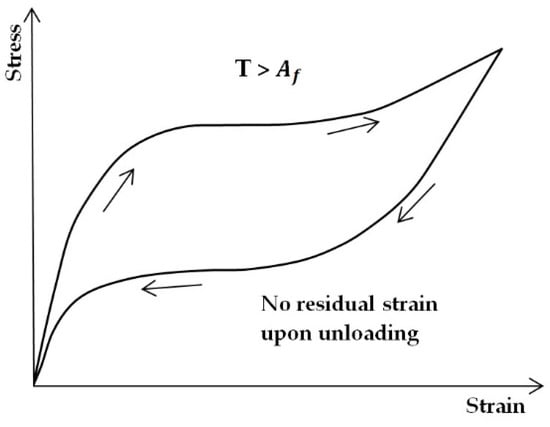
Figure 1.
Super-elastic behavior of SMA.
Since Bohler first found Nitinol in 1963, various types of shape memory alloys have been presented (Arghavani [32]). The most common ones are categorized into nitinol-based, copper-based, and iron-based SMAs. Among these, NiTi has considerably attracted the attention of researchers, and it is widely applied for commercial purposes. This alloy is available in the form of a wire, bar, pipe, and plate. This alloy can hold the maximum super-elastic strain of 8% without permanent damage. Besides, Nitinol has high erosion resistance (Ozbulut [33]). Copper-based alloys are cheaper than nitinol-based ones. Moreover, they can be easily manufactured in any shape and size. Additionally, their transformation occurs in a wider temperature range. For instance, CuALBe super-elastically behaves at temperatures between −65 and 180 °C. For this reason, it can be used for seismic applications in cold regions. However, this alloy can hold the maximum super-elastic strain between 2% and 4% without permanent damage (Ozbulut [33]). Also, due to martensite stabilization, this alloy shows aging at room temperature. Because iron-based SMAs, such as FeMnSi, FeNiC, and FeNiCoTi, are not expensive, they can be used instead of nitinol-based and copper-based shape memory alloys. It should be mentioned that iron-based SMAs, which have super-elastic behavior at room temperature, were found a few years ago. In 2010, an iron-based alloy was found, which could hold the maximum super-elastic strain of 15%. It was a combination of Fe, Ni, Co, Al, Ta, and B. The tensile strength of this alloy is higher than 1 Gpa, and its austenite phase finishes at the temperature of −62 °C (Ozbulut [33] and Hedayati Dezfuli and Alam [6]). Therefore, it is proper for cold regions. By investigating various alloys, the iron-based alloy FeNiCoAlTaB was applied with LRB isolators in this research with 13.5% maximum super-elastic strain.
3. Benchmark Highway Bridge
Since benchmark structures are essential for comparing various control approaches, it was decided that a benchmark structural control model for highway bridges would be developed during the meeting of the ASCE (American Society of Civil Engineering) committee in 2003. For this purpose, bridge 91.5, located in Orange County of Southern California, was selected. This is a continuous, pre-stressed concrete box-girder bridge, with two spans with a length of 58.5 m and two abutments skewed at 33 degrees. The deck is supported by a pre-stressed outrigger with a 31.4-m length and 6.9-m height, resting on two pile groups. The columns are around 6.9 m high. More details about this 4-line bridge are available in the definition paper [18]. A three-dimensional model of this bridge was developed using ABAQUS software. This process included two phases. In the first one, eight seismic isolators were applied to separate the bridge from its end abutments. At this stage, the deck was connected to the central pier (semi-isolated model) (Agrawal et al. [18]). In the second phase, two isolators were used in the middle piers in addition to the eight aforesaid isolators (completely isolated model) (Nagarajaiah et al. [26]). The second model was applied in this research, as shown in Figure 2.
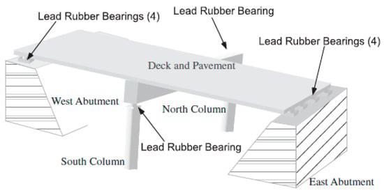
Figure 2.
Schematic picture of the benchmark bridge [26].
In the second model, Nagarajaiah et al. [26] assumed that the bridge superstructure, including the deck and the beam, has elastic behavior. The soil–structure interaction was considered at the end of the abutments and embankments. This effect was modeled by utilizing the springs and dashpots independent of the frequency, and the base isolators were modeled as shear elements. Therefore, their torsional rigidity and flexural stiffness were initialized to 0, and their vertical axial stiffness initialized to approach infinity. The bearings were idealized by the bi-directional bilinear plasticity model, as described by Makris and Zhang [1]. They wrote this model in ABAQUS as a subroutine. The aforesaid model can be mathematically introduced by utilizing Equations (1) and (2). The nonlinear behavior of the isolator in the X-direction is independent of its behavior in the Y-direction. It means that the restoring force in the X-direction is only related to the displacement in direction X. Also, the mass and damping of these bearings are eliminated. In these equations, and are the restoring forces in the X and Y directions, respectively, and are the post-yield stiffness of the isolator in the X and Y directions, respectively, and and are the pre-yield stiffness of the isolators in the X and Y directions, respectively. The yield displacements in the X and Y directions are denoted by and , respectively:
After developing the three-dimensional model of the bridge with 430 degrees of freedom, Nagarajaiah et al. [26] calculated the mass, stiffness, and damping matrices. In this process, the nonlinearity effects were considered. The dynamic equation of this nonlinear model is expressed in the form of Equation (3). In this equation, the incremental displacement, ground acceleration (including two horizontal components), incremental controlling force, mass, and stiffness matrices are denoted by U, , F, M, and K, respectively. Note that the stiffness matrix of the structure includes linear and nonlinear sub-matrices. η and b are the loading vectors for the ground acceleration and control forces, respectively:
Equation (3) can be solved with the help of the Newmark integration tactic. Although MATLAB software has various tools for solving ordinary differential equations, they are not able to find the nonlinear structural responses. For this reason, an S-Function program in the Simulink was developed for the bridge model by Nagarajaiah et al. [26]. Its input is the ground motion and control forces, and its output is the seismic responses of the bridge under nonlinear dynamic time history analysis. In Figure 3, the Simulink of the passive control device is shown. In the current work, the developed program is called in the box of the control device. Then, by entering the displacements of the isolator at each step, the force applied to the bridge by the passive control device is calculated and returns to the Simulink as an output. In the benchmark bridge package, six earthquake records are presented. Each ground motion contains two horizontal components in the X and Y directions, and their important properties are listed in Table 1. Also, 21 parameters are suggested for assessing various devices under these earthquakes. The last five parameters were not applied because the device of the current work was passive, and it required no sensor or control algorithm. The evaluation criteria are tabulated in Table 2, and readers are referred to [18] for more information on the bridge.
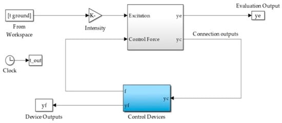
Figure 3.
Passive Simulink model of the benchmark bridge [26].

Table 1.
Properties of earthquake records.

Table 2.
Summary of the evaluation criteria.
4. Modeling the SMA-LRB Isolator
In this research, the finite element approach was applied to investigate the effect of earthquakes on the benchmark bridge and its control device. This process included various stages. The most crucial stage is related to modeling the material behavior. The selected model should be able to simulate the actual behavior of the material numerically.
The applied controlled device includes an LRB isolator and double-cross SMA wires. These wires are made up of FeNiCoAlTaB. This configuration of wires was suggested after studying and comparing various configurations (Hedayati Dezfuli and Alam [6]). This isolator is schematically shown in Figure 4. The SMA wires were added to LRB isolators with the purposes of controlling displacement, and enhancing the re-centering property and damping capacity. The SMA wires were installed on the specific points of the isolator using the steel hooks. For simplification and avoiding numerical divergence, it was assumed that the friction between the wires and hooks was negligible (Hedayati Dezfuli and Alam [6]).
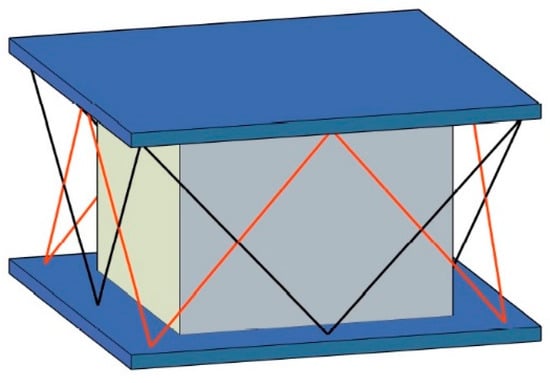
Figure 4.
Double cross configuration of SMA-LRB.
In this paper, the constitutive model of intelligent isolators developed by Hedayati Dezfuli and Alam [7] was used. In this model, the SMA isolator is divided into two separate systems (i.e., SMA wires and LRB isolator) based on the superposition principle. First, the hysteresis curve is found for each device. Second, they are added to each other to form the hysteresis behavior of the SMA device. This method was assessed by performing the finite element analysis of the discrete and continuous systems, using ANSYS software (Hedayati Dezfuli and Alam [7]).
4.1. The Hysteresis Model of LRB
In this study, the behavior of LRB isolators was modeled using a bilinear kinetic hardening model to simplify the finite element analysis procedure (Hedayati Dezfuli and Alam [7], Attanasi et al. [34], Mauro et al. [35], Casciati et al. [28]). In this model, three parameters exist, including the yield stress, , initial stiffness, , and the post-yield hardening ratio, r. These parameters are required for finding the force–displacement curve. This model is available in some software. In this case, the available code in the benchmark bridge package was applied. Characteristics of the benchmark bridge LRBs are shown in Table 3. Figure 5 depicts the force–displacement curve of the mid-pier LRB under the North Palm Springs earthquake.

Table 3.
LRB characteristics of the benchmark bridge.
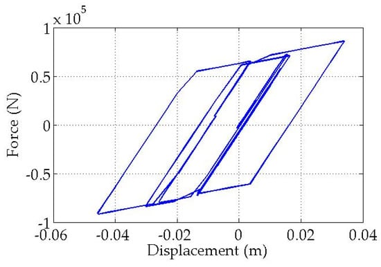
Figure 5.
Hysteresis of the mid-pier LRB under North Palm Springs Earthquake.
4.2. The Hysteresis Model of SMA Wires
Hedayati Dezfuli and Alam [7] calculated the axial force of the wires at different levels of shear strain instead of modeling the connection in detail. By specifying the geometrical properties of the isolator and wires, the strain was found for each time step. With the help of the constitutive model of SMA, this strain was converted into the axial stress of the wire. Finally, the axial force was expressed in terms of time and applied to the LRB isolator as an external force. In [7], this process is presented in detail. To find the hysteresis curves of the SMA wire, a MATLAB function was developed by the authors based on the presented algorithm of Hedayati Dezfouli and Alam. The results obtained from the written code (PCODE) are illustrated in Figure 6 and compared with the source data (MCODE) for various loadings (E5, E6, E7, and E8). It should be noted that as Hedayati Dezfouli and Alam [7] pointed out, the shear hysteresis of the SMA wires is not the same as the flag-shaped hysteresis of the SMA, due to the effect of the wire’s configuration on the transferred force to the LRBs. Moreover, the developed hysteresis model by Hedayati Dezfuli and Alam [7] is independent of the strain rate effect, and further research needs to be conducted to investigate the influence of strain rate on the hysteresis of SMA-LRBs.
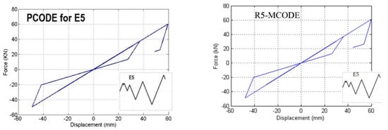
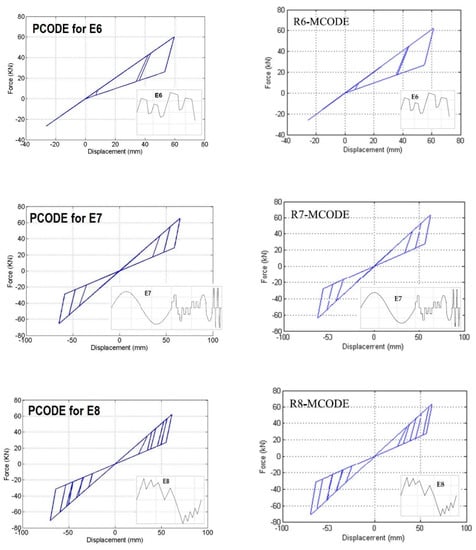
Figure 6.
Hysteresis curve plotted by this paper’s written code (PCODE), and with Hedayati Dezfuli and Alam (MCODE) [7].
4.3. Optimizing the SMA-LRB Isolator
Hedayati Dezfuli and Alam [7] proved that the hysteresis behavior of SMA was related to various parameters, including the base isolator’s size, radius of the wire, and temperature. This research used the SMA wire as a supplementary element to the base isolators of the benchmark bridge to improve its seismic performance without changing its LRBs. Moreover, it was assumed that the temperature was constant and equal to 20 °C, and only the radius of the wire was unknown. This parameter has a profound effect on the force applied to the LRB isolator. Increasing the wire’s radius led to an increase in the re-centering-induced force from the wire to the LRB and consequently an increase in the horizontal stiffness of the isolators. As a result, by increasing the radius of the wire, the residual deformation is reduced, but the base shear force and the deck acceleration of the bridge increase.
In this work, an evolutionary optimization algorithm named NSGA-II (non-dominated sorting genetic algorithm) was utilized to find the optimum radius of the wires for each earthquake record. The non-dominated sorting genetic algorithm type II is a multi-objective genetic algorithm, proposed by Deb et al. [36]. It is an extension and improvement of NSGA, which was proposed earlier by Srinivas and Deb [37]. In the structure of NSGA-II, in addition to genetic operators (crossover and mutation), two specialized operators are defined and utilized. The first operator is called non-dominated sorting, in which the population is sorted and partitioned into fronts (F1, F2, etc.), where F1 indicates the approximated Pareto front. The second one is the crowding distance, which indicates a mechanism of ranking among members of a front, which are dominating or dominated by each other. These ranking mechanisms are used with genetic selection operators to create the population of the next generation. Figure 7 depicts the flow chart of NSGA-II (Kim et al. [38]).
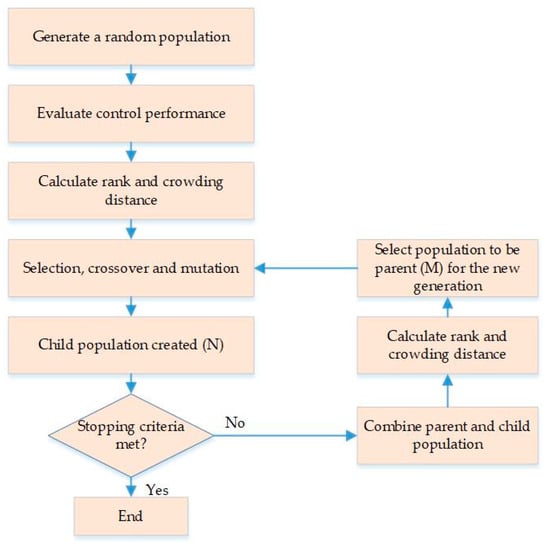
Figure 7.
Flow chart of NSGA-II (Kim et al. [38]).
It is worthwhile to mention that the used algorithm in this project includes two objective functions, which are parameters J1 and J3. As can be seen in Table 2, these parameters are the maximum base shear force of the controlled bridge normalized with respect to the maximum base shear force of the uncontrolled structure and the maximum mid-span displacement of the controlled bridge normalized with respect to the corresponding displacement of the uncontrolled structure, respectively. For each earthquake, the population included 40 members, and it was assumed that the maximum number of iterations was equal to 40. The mutation and crossover rates were 0.4 and 0.7, respectively. Using these parameters and the algorithm mentioned previously, the Pareto front was achieved, which contained the points simultaneously and independently minimized J1 and J3 for an earthquake record. For the far-field North Palm Springs earthquake, Figure 8 presents the optimized points. This algorithm can find more counts of optimum points by increasing the population size and the maximum iteration. However, the runtime also increases. Choosing the desired radius among these points depends on the designer’s purpose. In this study, the main aim was to alleviate displacements, so among the optimum points with the least J3, the point with minimum J1 was picked. Consequently, the optimum radius was 6 mm for the North Palm Springs earthquake. This process was repeated for other earthquakes. The obtained results are tabulated in Table 4.
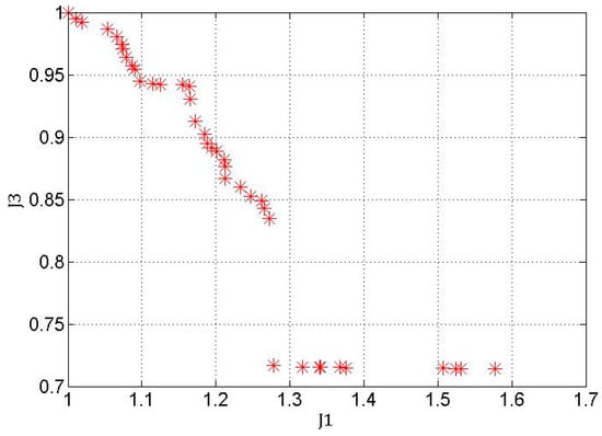
Figure 8.
Pareto front of NSGA-II under North Palm Spring.

Table 4.
Optimized radii obtained from NSGA-II for each ground motion record.
As can be seen in Table 4, in total, four different radii are represented as the result of the optimization. However, among these four radii, only one single radius should be selected, which is able to minimize J1 and J3 simultaneously under all earthquakes, better than the other radii. To identify the final radius, two steps need to be taken. Firstly, for each earthquake record, the performance of the isolated bridge equipped with each of the four optimized SMA diameters was collected. It should be noted that, because the main aim of this research was to minimize displacements while controlling the base shear, among different evaluation criteria, only J1 and J3 were utilized to assess the best radius of the wire. Therefore, the selected nonlinear dynamic analysis results for different radii under all records are depicted in Table 5. Secondly, in order to choose the radius with the best overall performance from the results shown in Table 5, the weighted sum method (WSM) was utilized. The WSM is the best known and commonly used multi-criteria decision-making method for evaluating a number of alternatives regarding a number of decision criteria. According to the WSM, in a decision problem with M alternatives and N criteria, a performance value can be calculated for each alternative by applying Equation (4). Then, in a minimization case, the best alternative is the one that yields the minimum total score:
where is the WSM score of the alternative, is the weight of importance of criteria, and is the actual value of the alternative regarding the criterion. In this research, the main goal was to minimize displacements rather than the base shear. As a result, the weights were set as 0.8 and 0.2 for J3 and J1, respectively. Rewriting Equation (4) for the current problem leads to Equation (5):

Table 5.
Nonlinear dynamic analysis results of the benchmark bridge equipped with different SMA-LRB isolators.
By substituting the numbers of Table 5 in Equation (5), the WSM scores were calculated as 5.708, 4.658, 5.026, and 5.246 for r = 1, 3.5, 4.5, and 6 mm, in turn. It is evident that the radius with the least score has superior performance in reducing the maximum base shear and the maximum mid-span displacement. Finally, the radius of 3.5 mm with the least objective function was selected as the optimum radius.
As reflected, the final optimum radius diverges from the optimized radii for some earthquake records. The reason is that these earthquakes were selected for the benchmark bridge so that they cover a broad range of spectral characteristics. However, for a bridge with specific conditions, the final optimized radius can be determined more precisely, and a higher improvement will be attained in the performance of the bridge.
5. Numerical Analysis
To assess the performance of the optimized SMA base isolator, the SMA wires with a radius of 3.5 mm were added to the LRBs of the benchmark bridge. Then, the nonlinear time history dynamic analysis was conducted. The behavior of the isolated structure under near-field earthquakes was different from its behavior under far-field earthquakes. The near-field records may include pulses with larger periods. Therefore, because of the long period of the isolated structure, the occurrence of resonance is probable. For this reason, the behavior of the bridge was evaluated during both far-field and near-field earthquakes, and their responses are tabulated in Table 6 and Table 7, respectively. In these tables, the responses of the current study are denoted as SRB.

Table 6.
Nonlinear dynamic analysis results of the benchmark bridge equipped with SMA-LRB isolators under far-field earthquakes.

Table 7.
Nonlinear dynamic analysis results of the benchmark bridge equipped with SMA isolators under near-field earthquake records.
For comparison, the responses of the nonlinear damper (N.D) derived from the research conducted by Nagarajaiah et al. [26], the passive damper device with SMA (Cu.D) obtained from the works carried out by Zhang et al. [27], and the new negative stiffness device (NSD) proposed by Li et al. [29] are also listed in Table 6 and Table 7. It should be mentioned that various devices were studied by Zhang et al. (2009). The results corresponding to the device compatible with the current research are presented. This device has no additional damping, and it works in the temperature of 23 °C. Moreover, a graphical demonstration of the four evaluation criteria resulted from the above four passive control systems is shown in Figure 9.
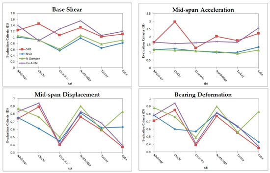
Figure 9.
Comparison of (a) base shear, (b) mid-span acceleration, (c) mid-span displacement, and (d) bearing deformation for four passive control systems.
5.1. Base Shear
The deck acceleration and base shear of the two-span continuous bridge are larger without a base isolation system (Phase I). By employing base isolators in the central pier of the bridge, its stiffness and the load transmitted from the base to the superstructure decreases (phase II). In Table 8, the responses of the uncontrolled bridge in both phases are presented, and the significant reduction in deck acceleration and base shear can be seen for all earthquakes after isolation (Agrawal et al. [18], Nagarajaiah et al. [26]). For example, under the North Palm Springs earthquake, the use of base isolation leads to an 88.24% and 82.37% reduction in the base shear and deck acceleration of the bridge, respectively.

Table 8.
Max base shear and mid-span acceleration of the bridge before and after isolation.
However, after isolating the superstructure, its displacements increase. For controlling these displacements, the SMA wires were employed. It is expected that adding the wires to the LRB of the bridge increases the horizontal stiffness and, consequently, the deck acceleration and base shear. The evaluation parameters related to the base shear are denoted by J1 and J9, which are the maximum base shear and the norm one normalized based on their uncontrolled quantities. According to Table 6, under far-field earthquakes, J1 goes up by 8% to 24%, and J9 increases by 8% to 36%. However, according to Figure 9a, this leads to increments less than the Cu-Al-Be device values.
In near-field earthquakes, J1 increases by 3% to 45%. Under the Turkey earthquake, J9 reduces by 41%, and this parameter increases by 8% to 53% under other earthquakes. Because the current work selected the radius of the SMA by minimizing J1, these increments in the base shear force are negligible in comparison to the initial reduction achieved by using the base isolator.
5.2. The Mid-Span Acceleration
J4 and J12 represent the maximum acceleration of the mid-span normalized with respect to uncontrolled acceleration and the norm of the acceleration normalized with respect to the corresponding parameter of the uncontrolled structure, respectively. In far-field earthquakes, J4 increases by 28% to 64%. As mentioned before, based on Table 8, the maximum acceleration of the mid-span after the usage of base isolators reduces by 82.37% under the North Palm Springs earthquake. Therefore, this increase is reasonable. Besides, J12 goes up by 29% to 37%.
In comparison to the case in which the structure is under the far-field earthquakes, a larger increment can be observed in the acceleration of the structure when it is under the near-field earthquake, and J4 increases by 76% to 197%. Also, J12 goes up by 36% to 130%. Figure 9b indicates that the mid-span acceleration of the benchmark bridge with optimized SRBs is generally larger than the other three systems.
5.3. The Mid-Span Displacement
By applying SMA wires, both the shear and acceleration increase, and the displacements decrease. In far-field earthquakes, the parameter J3 reduces by 26% to 60%. This parameter is related to the maximum displacement of the mid-span of the controlled structure normalized with respect to the corresponding parameter of the uncontrolled structure. Furthermore, the norm of the mid-span displacement of the controlled structure normalized with respect to the corresponding parameter of the uncontrolled structure, i.e., J11, reduces by 49% to 72%. Also, SRB is more successful than other control devices in reducing the displacements under far-field earthquakes. Figure 10 displays the time history curve of the mid-span displacement for the controlled and uncontrolled structures in two directions, i.e., X and Y, under the far-field North Palm Springs earthquake.

Figure 10.
Time history curve of the mid-span displacement under far-field North Palm Springs in the (a) X and (b) Y directions.
Under the near-field earthquakes, J3 reduces by 11% to 61%, and J11 reduces by 19% to 74%. Moreover, as can be seen in Figure 9c, except for the Chi-Chi record, SRB is the superior passive device in the reduction of mid-span displacements.
5.4. Base Isolator Deformation
In far-field earthquakes, the maximum deformation of the base isolator in the controlled structure normalized with the corresponding parameter of the uncontrolled structure, J5, reduces by 29% to 61%. Also, the norm of the base isolator deformation of the controlled structure normalized with respect to the corresponding parameter of the uncontrolled structure, J13, decreases by 41% to 73%. Under near-field earthquakes, parameter J5 reduces by 15% to 65% and J13 reduces by 21% to 74%. Based on Figure 9d, it is evident that, in general, the performance of the optimized SRB is more proper than other approaches under all earthquakes.
5.5. Residual Deformation
In the represented benchmark bridge package, there is no independent parameter indicating the residual deformations of different points of the bridge. However, this value can be extracted from the displacement history curve of each point. As can be seen in Figure 10a,b, for the SRB controlled bridge, the residual mid-span displacements in the X direction do not exist after the North Palm Springs earthquake, and the residual displacements in the Y direction decrease by 80%. The mid-span residual deformation under far-field and near-field earthquakes before and after applying the SRB in two directions, i.e., X and Y, are presented in Table 9 and Figure 11. As can be seen, the bridge with optimized SRBs is capable of reducing the residual deformations significantly.

Table 9.
The mid-span residual deformation values before and after applying the SRB, in two directions, X and Y.
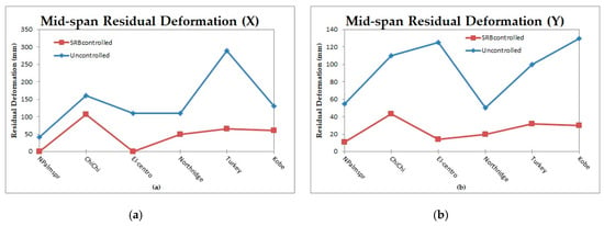
Figure 11.
Graphical demonstration of the mid-span residual deformation before and after the SRBs in the (a) X and (b) Y directions.
6. Conclusions
By employing base isolators in the central pier of the benchmark bridge as a passive control strategy against seismic loadings, its stiffness and the load transmitted from the base to the superstructure decreased. On the other hand, the superstructure displacements increased. To control these displacements, SMA wires were utilized. However, adding the wires to the LRBs of the bridge increased the horizontal stiffness and, consequently, the deck acceleration and base shear. In order to get the best performance out of SMA wires, multi-objective optimization can be applied. Therefore, in this paper, the SMA wires were firstly optimized with the help of a multi-objective optimization algorithm named NSGA-II and the weighted sum method, and then added to the LRB isolators of the isolated benchmark bridge to reduce the residual deformations and displacements under the earthquakes available in the benchmark bridge package. In this way, the maximum mid-span displacement of the bridge and the maximum base shear force were simultaneously minimized. To assess the ability of this optimized system, the method was compared with the other three passive control approaches on the phase II of the benchmark bridge (Nagarajaiah et al. [26], Zhang et al. [27] and Li et al. [29]). Considering 16 main parameters, the results obtained by the nonlinear dynamic analysis of the benchmark structure under six different earthquakes were summarized.
As regards far-field earthquakes, the suggested passive control device on average reduced the maximum mid-span displacement of the bridge and the maximum deformation of the base isolators by 43% and 45%, respectively. Also, the residual mid-span displacements of the bridge in the X- and Y-directions declined by 100% and 84.4%, respectively, on average. Nevertheless, using this device led to an average 16% and 46% rise in the base shear force and the maximum deck acceleration of the bridge, respectively.
Regarding near-field earthquakes, by using this device, the maximum mid-span displacement and the maximum base isolator deformation reduced by 34% and 37%, respectively. On average, applying this system resulted in a 55% and 66% reduction in the residual mid-span displacements of the bridge in the X and Y directions, respectively. However, the SMA controller increased the base shear force and the maximum deck acceleration of the bridge by 23% and 124%, respectively, on average.
As for comparing different passive devices, in general, using optimized SMA-LRB resulted in a drop of the mid-span displacement and bearing deformation more than the other measures. For example, it reduced the maximum bearing deformation by up to 58%, 31%, and 14% more than the non-linear dampers, negative stiffness device, and Cu-Al-Be dampers, respectively. It is undeniable that the base shear and mid-span acceleration of SRB are generally more than other controllers. However, the optimization kept them within bounds and still less than the figures before the isolation of the bridge.
Comparing the two SMA passive controllers, i.e., Cu.D and SRB, revealed that the overall performance of the SRB is superior to the Cu.D. First of all, as said above, the SRB reduced the displacements more than the Cu.D. Secondly, the SRB increased the base shear of the bridge less than the Cu.D. Also, the manufacturing process of the Cu.D is more complicated and more expensive than implementing SMA wires in the LRBs of the bridge.
Here, SMA wires were added to the existing LRBs of the bridge in a double-cross configuration. In future studies, various LRBs (different sizes and characteristics) with different wire configurations (straight and cross) need to be evaluated. Furthermore, in the benchmark bridge package, only six earthquake records were presented. Nonetheless, the seismic incident is innately random, and a set of deterministic ground motion is often not adequate to denote the uncertainty involved in seismic loading. Therefore, new analysis and optimization based on the random vibration framework should be conducted. In addition, as mentioned before, the utilized hysteresis model for the SMA wires is independent of the strain rate; as a result, the optimization approach was done by disregarding the sensitivity of the structure and materials to the strain rate effect. However, since this factor can influence the hysteresis loop of the SMA device and thus affect the behavior of the system, additional research and optimization considering the strain rate effect are required. Finally, SMAs have thermomechanical behavior, which means both thermal and mechanical loadings affect their response; however, in this paper, the ambient temperature was assumed to be constant and equal to 20 °C during an earthquake. Further research needs to be carried out on the effect of varying temperature on the performance of bridges equipped with SMA-LRBs.
Author Contributions
Conceptualization, Methodology, Investigation, Data Curation, Formal Analysis, Software and Writing—original draft, R.H.; Supervision and Project administration, M.R. and B.S.; Validation, F.H.D.; Visualization, K.K.A.; Writing—Review and Editing, R.H., M.R., F.H.D., K.K.A., and B.S. All authors have read and agreed to the published version of the manuscript.
Funding
This research received no external funding.
Conflicts of Interest
The authors declare no conflict of interest.
References
- Makris, N.; Zhang, J. Seismic Response Analysis of a Highway Overcrossing Equipped with Elastomeric Bearings and Fluid Dampers. J. Struct. Eng. 2004, 130, 830–845. [Google Scholar] [CrossRef]
- Soneji, B.B.; Jangid, R.S. Passive hybrid systems for earthquake protection of cable-stayed bridge. Eng. Struct. 2007, 29, 57–70. [Google Scholar] [CrossRef]
- Dicleli, M. Supplemental elastic stiffness to reduce isolator displacements for seismic-isolated bridges in near-fault zones. Eng. Struct. 2007, 29, 763–775. [Google Scholar] [CrossRef]
- Wilde, K.; Gardoni, P.; Fujino, Y. Base isolation system with shape memory alloy device for elevated highway bridges. Eng. Struct. 2000, 22, 222–229. [Google Scholar] [CrossRef]
- Choi, E.; Nam, T.; Cho, B.S. A new concept of isolation bearings for highway steel bridges using shape memory alloys. Can. J. Civ. Eng. 2005, 32, 957–967. [Google Scholar] [CrossRef]
- Hedayati Dezfuli, F.; Alam, M.S. Shape memory alloy wire-based smart natural rubber bearing. Smart Mater. Struct. 2013, 22, 45013–45030. [Google Scholar] [CrossRef]
- Hedayati Dezfuli, F.; Alam, M.S. Hysteresis model of shape memory alloy wire-based laminated rubber bearing under compression and unidirectional shear loadings. Smart Mater. Struct. 2015, 24, 065022–065041. [Google Scholar] [CrossRef]
- Hedayati Dezfuli, F.; Li, S.; Alam, M.S.; Wang, J.Q. Effect of constitutive models on the seismic response of an SMA-LRB isolated highway bridge. Eng. Struct. 2017, 148, 113–125. [Google Scholar] [CrossRef]
- Xiang, N.; Alam, M.S. Comparative Seismic Fragility Assessment of an Existing Isolated Continuous Bridge Retrofitted with Different Energy Dissipation Devices. J. Bridge Eng. 2019, 24, 04019070–04019087. [Google Scholar] [CrossRef]
- Andrawes, B.; DesRoches, R. Comparison between Shape Memory Alloy Seismic Restrainers and Other Bridge Retrofit Devices. J. Bridge Eng. 2007, 12, 700–709. [Google Scholar] [CrossRef]
- Ozbulut, O.E.; Hurlebaus, S. Seismic assessment of bridge structures isolated by a shape memory alloy/rubber-based isolation system. Smart Mater. Struct. 2011, 20, 015003–015015. [Google Scholar] [CrossRef]
- Rahman Bhuiyan, A.; Alam, M.S. Seismic performance assessment of highway bridges equipped with superelastic shape memory alloy-based laminated rubber isolation bearing. Eng. Struct. 2013, 49, 396–407. [Google Scholar] [CrossRef]
- Zhu, S.Y.; Qiu, C.X. Incremental Dynamic Analysis of Highway Bridges with Novel Shape Memory Alloy Isolators. Adv. Struct. Eng. 2014, 17, 429–438. [Google Scholar] [CrossRef]
- Mishra, S.K.; Gur, S.; Roy, K.; Chakraborty, S. Response of Bridges Isolated by Shape Memory–Alloy Rubber Bearing. J. Bridge Eng. 2016, 21, 04015071–04015086. [Google Scholar] [CrossRef]
- Choi, E.; Jeon, J.S.; Kim, W.J.; Kang, J.W. Investigation of MRS and SMA Dampers Effects on Bridge Seismic Resistance Employing Analytical Models. Int. J. Steel Struct. 2018, 18, 1325–1335. [Google Scholar] [CrossRef]
- Li, S.; Mao, C. Comparative study of two types of self-recovery shape-memory alloy pseudo-rubber isolator devices under compression–shear interactions. J. Intell. Mater. Syst. Struct. 2019, 30, 2241–2256. [Google Scholar] [CrossRef]
- Wang, J.Q.; Li, S.; Hedayati Dezfuli, F.; Alam, M.S. Sensitivity analysis and multi-criteria optimization of SMA cable restrainers for longitudinal seismic protection of isolated simply supported highway bridges. Eng. Struct. 2019, 189, 509–522. [Google Scholar] [CrossRef]
- Agrawal, A.; Tan, P.; Nagarajaiah, S.; Zhang, J. Benchmark structural control problem for a seismically excited highway bridge-Part I: Phase I Problem definition. Struct. Control Heal. Monit. 2009, 16, 509–529. [Google Scholar] [CrossRef]
- Tan, P.; Agrawal, A.K. Benchmark structural control problem for a seismically excited highway bridge-part II: Phase I sample control designs. Struct. Control Heal. Monit. 2009, 16, 530–548. [Google Scholar] [CrossRef]
- Madhekar, S.N.; Jangid, R.S. Variable dampers for earthquake protection of benchmark highway bridges. Smart Mater. Struct. 2009, 18, 115011–115029. [Google Scholar] [CrossRef]
- Madhekar, S.N.; Jangid, R.S. Seismic performance of benchmark highway bridge installed with piezoelectric friction dampers. IES J. Part A Civ. Struct. Eng. 2011, 4, 191–212. [Google Scholar] [CrossRef]
- Madhekar, S.N. Seismic Performance of Benchmark Highway Bridge Installed with Passive Control Devices. Adv. Struct. Eng. 2015, 2, 1377–1390. [Google Scholar]
- Saha, A.; Saha, P.; Patro, S.K. Seismic response control of benchmark highway bridge using non-linear FV spring damper. IES J. Part A Civ. Struct. Eng. 2015, 8, 240–250. [Google Scholar] [CrossRef]
- Saha, A.; Saha, P.; Patro, S.K. Polynomial friction pendulum isolators (PFPIs) for seismic performance control of benchmark highway bridge. Earthq. Eng. Eng. Vib. 2017, 16, 827–840. [Google Scholar] [CrossRef]
- Saha, A.; Saha, P.; Patro, S.K. Seismic protection of the benchmark highway bridge with passive hybrid control system. Earthq. Struct. 2018, 15, 227–241. [Google Scholar]
- Nagarajaiah, S.; Narasimhan, S.; Agrawal, A.; Tan, P. Benchmark structural control problem for a seismically excited highway bridge-Part III: Phase II Sample controller for the fully base-isolated case. Struct. Control Heal. Monit. 2009, 16, 549–563. [Google Scholar] [CrossRef]
- Zhang, Y.; Hu, X.; Zhu, S. Seismic performance of benchmark base-isolated bridges with superelastic Cu-Al-Be restraining damping device. Struct. Control Heal. Monit. 2009, 16, 668–685. [Google Scholar] [CrossRef]
- Casciati, F.; Faravelli, L.; Al Saleh, R. An SMA passive device proposed within the highway bridge benchmark. Struct. Control Heal. Monit. 2009, 16, 657–667. [Google Scholar] [CrossRef]
- Li, H.N.; Sun, T.; Lai, Z.; Nagarajaiah, S. Effectiveness of Negative Stiffness System in the Benchmark Structural-Control Problem for Seismically Excited Highway Bridges. J. Bridge Eng. 2018, 23, 1–11. [Google Scholar] [CrossRef]
- Paiva, A.; Savi, M.A. An overview of constitutive models for shape memory alloys. Math. Probl. Eng. 2006, 2006, 1–30. [Google Scholar] [CrossRef]
- Lagoudas, D.C. Shape Memory Alloys Modeling and Engineering Applications; Springer: Boston, MA, USA, 2008. [Google Scholar]
- Arghavani, J. Thermo-Mechanical Behavior of Shape Memory Alloys under Multiaxial Loading: Constitutive Modeling and Numerical Implementation at Small and Finite Strains. Ph.D. Dissertation, Sharif University of Technology, Tehran, Iran, 2010. [Google Scholar]
- Ozbulut, O.E. Seismic Protection of Bridge Structures Using Shape Memory Alloy-Based Isolation Systems Against Near-Field Earthquakes. Ph.D. Dissertation, Texas A&M University, Texas, TX, USA, 2010. [Google Scholar]
- Attanasi, G.; Auricchio, F.; Fenves, G.L. Feasibility Assessment of an Innovative Isolation Bearing System with Shape Memory Alloys. J. Earthq. Eng. 2009, 13, 18–39. [Google Scholar] [CrossRef]
- Mauro, D.; Donatello, C.; Roberto, M. Implementation and testing of passive control devices based on shape memory alloys. Earthq. Eng. Struct. Dyn. 2000, 29, 945–968. [Google Scholar]
- Deb, K.; Pratap, A.; Agarwal, S.; Meyarivan, T. A fast and elitist multiobjective genetic algorithm: NSGA-II. IEEE Trans. Evol. Comput. 2002, 6, 182–197. [Google Scholar] [CrossRef]
- Srinivas, N.; Deb, K. Muiltiobjective Optimization Using Nondominated Sorting in Genetic Algorithms. Evol. Comput. 1994, 2, 221–248. [Google Scholar] [CrossRef]
- Kim, H.; Chang, C.; Kang, J. Evaluation of Microvibration Control Performance of a Smart Base Isolation System. Int. J. Steel Struct. 2015, 15, 1011–1020. [Google Scholar] [CrossRef]
© 2019 by the authors. Licensee MDPI, Basel, Switzerland. This article is an open access article distributed under the terms and conditions of the Creative Commons Attribution (CC BY) license (http://creativecommons.org/licenses/by/4.0/).