Multi-Country Analysis on Energy Savings in Buildings by Means of a Micro-Solar Organic Rankine Cycle System: A Simulation Study

 ,
,  ,
, 
 ,
, 
Abstract
1. Introduction
- The micro-CHP thermal and electric energy production is calculated for different European cities;
- The coupling between the micro-CHP system and different dwellings from the considered European cities is investigated by means of simulation models;
- The primary energy savings and cost savings compared to traditional production technologies allowed by the integration of the micro-CHP in such buildings are assessed together with the wasted thermal energy produced by the ORC and not usefully recovered.
2. Materials and Methods
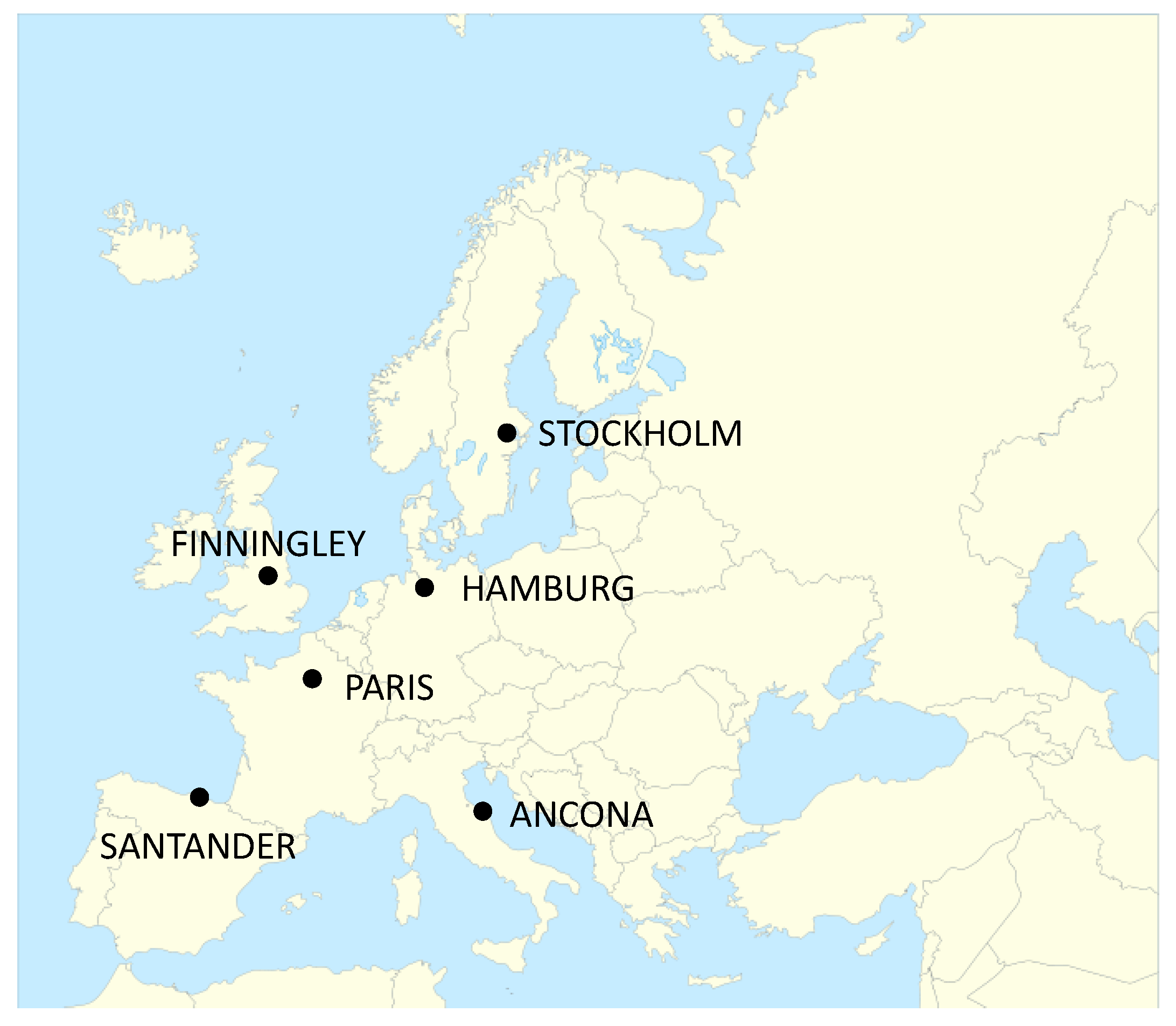
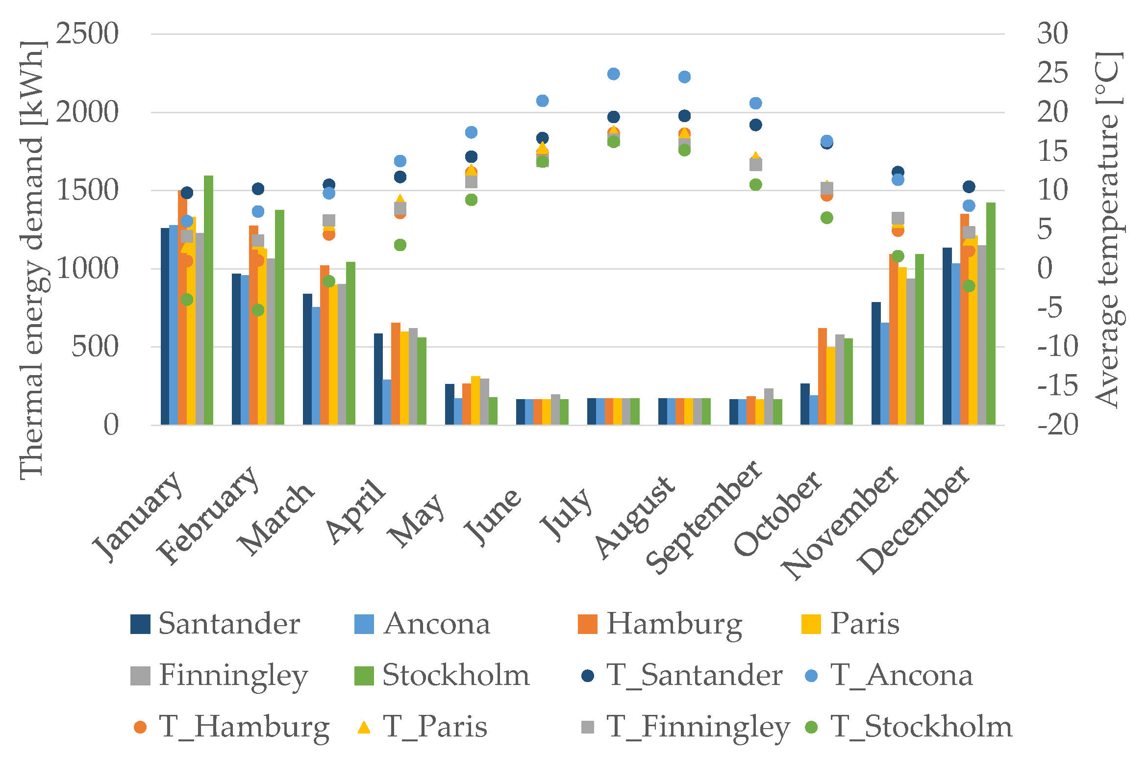
2.1. Climatic Conditions
2.2. Building Specification
3. Simulation Models
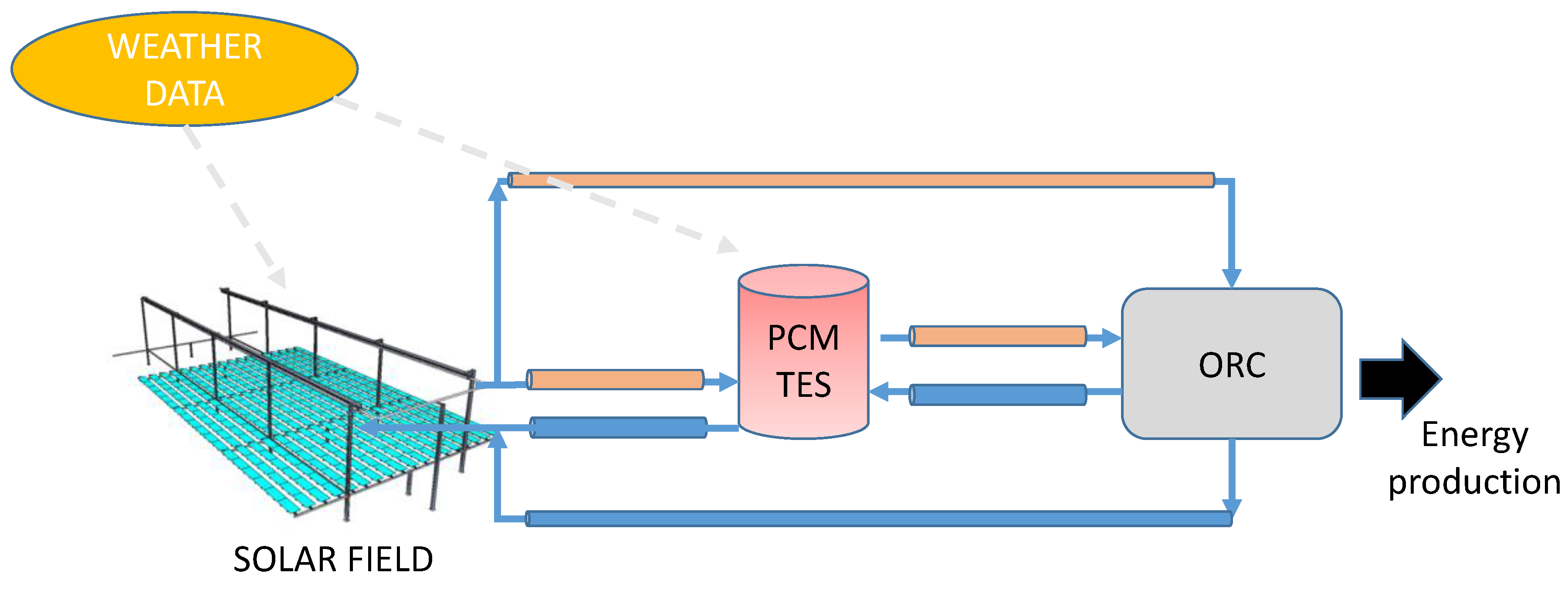
3.1. Micro-Solar Orc Plant
- a minimum superheating at the evaporator of 5 °C;
- no subcooling at the outlet of the condenser;
- an organic working fluid flow rate of 0.21 kg/s at nominal operating conditions, which was adjusted, at every time step, in order to maintain the minimum superheating at the evaporator outlet;
- a generator electric efficiency equal to 0.9 and a mechanical efficiency of 0.95;
- a constant overall heat transfer efficiency of the heat exchangers.
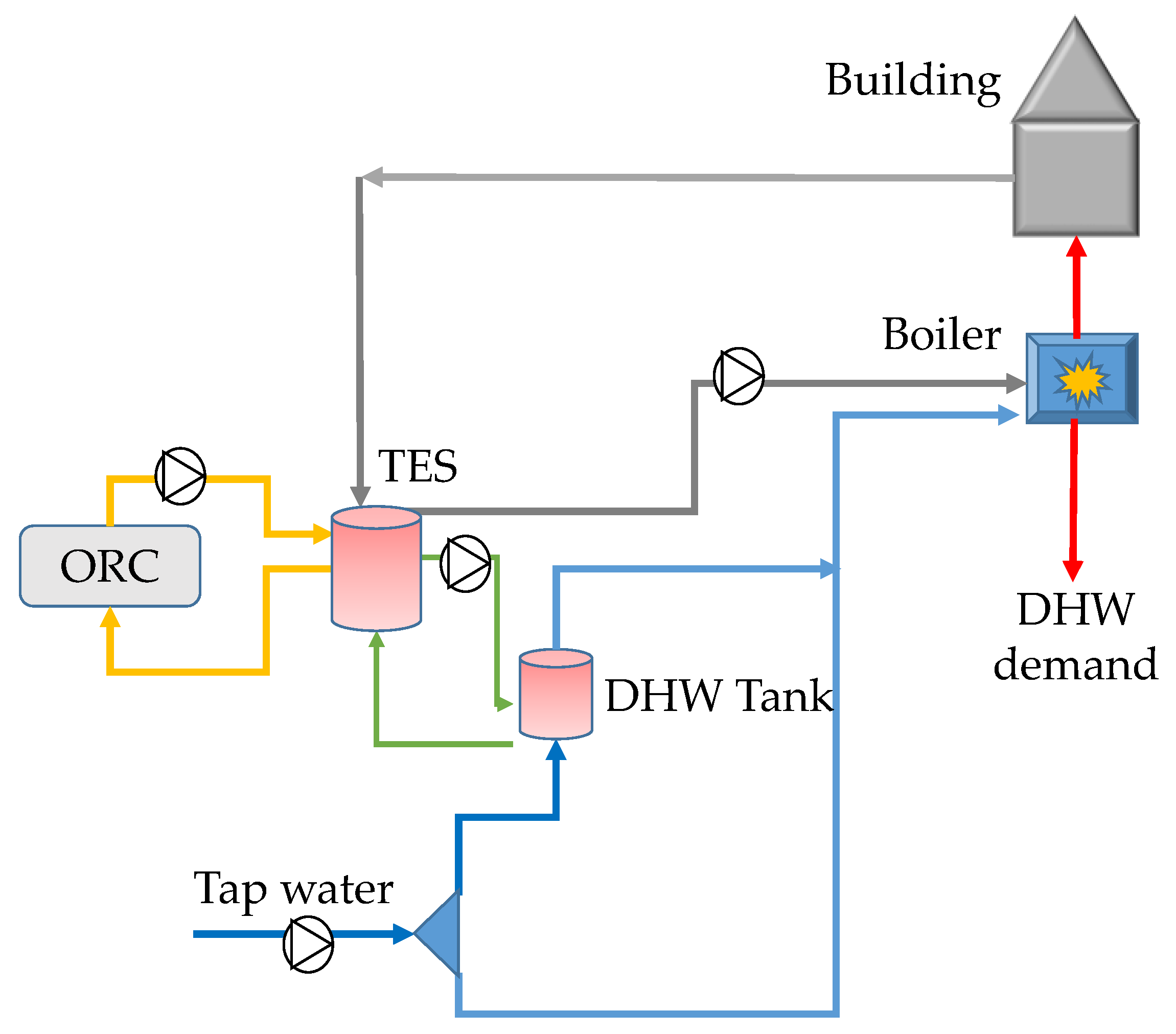
3.2. Building Model
4. Results and Discussion
5. Conclusions
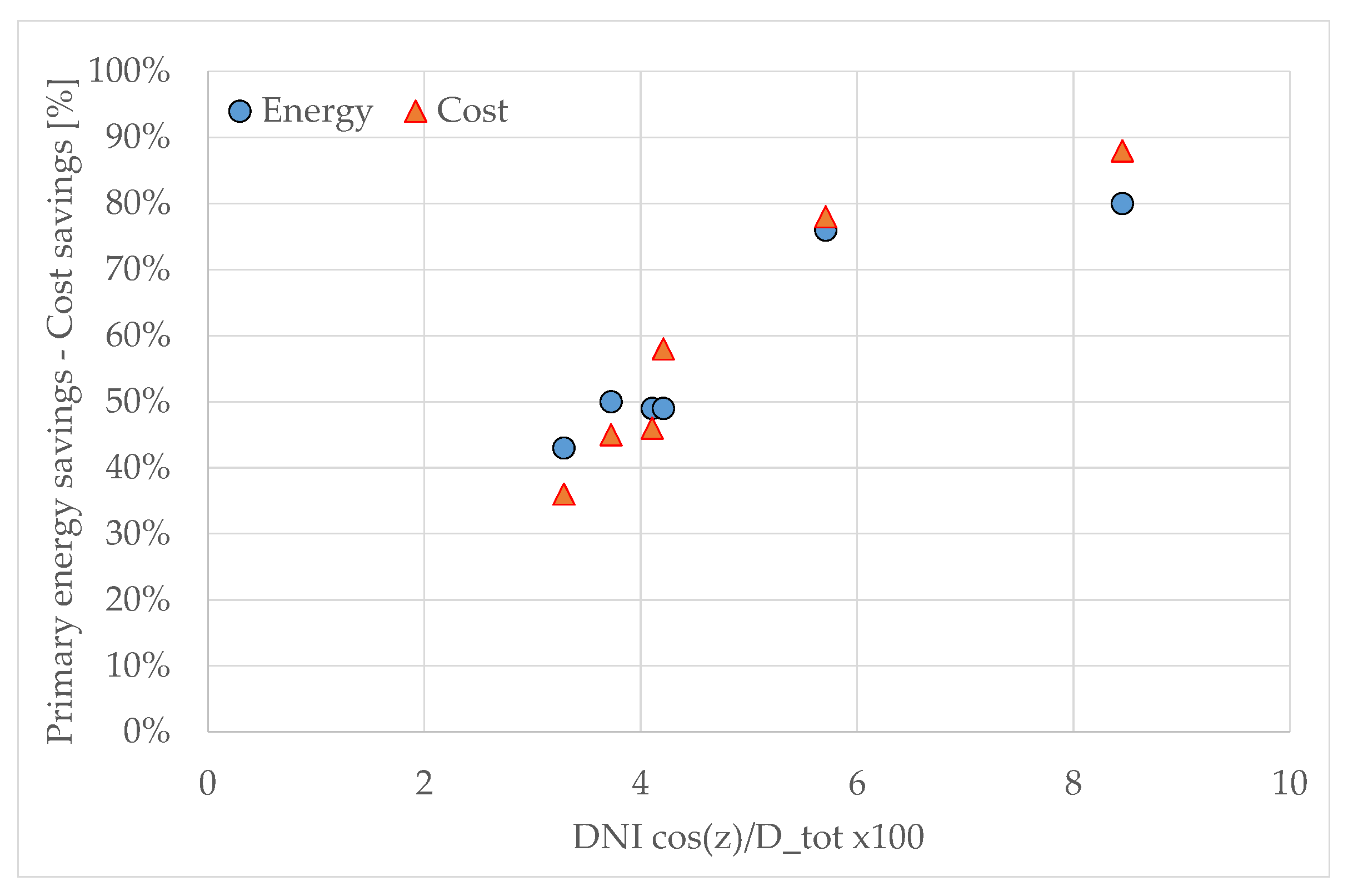
- The plant had the best performance in southern Europe because the plant energy production was higher, while the energy demand is lower.
- The microsolar CHP system can satisfy almost 80% of the energy demand (thermal and electric) for a dwelling in locations of southern Europe, while about 50% in locations of central and northern Europe.
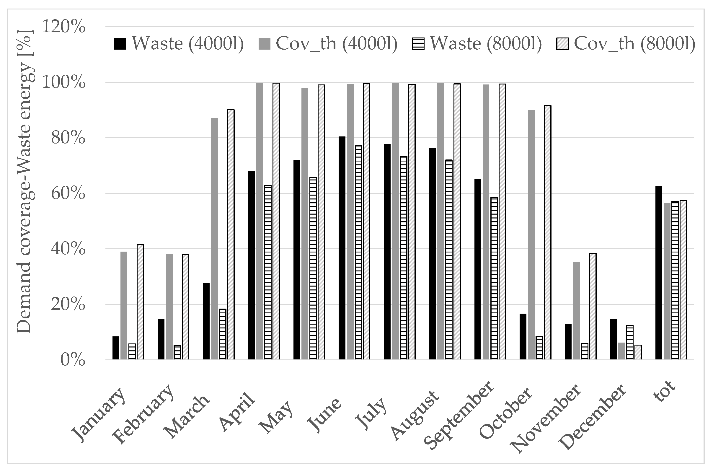
- By increasing the number of dwellings, the energy demand coverage decreased less than proportionally.
- A huge amount of the heat produced was always wasted because the building’s thermal demand was too low in summer when the production was high. A bigger thermal energy storage could partially solve this issue or the excess heat available could be used for other purposes (e.g., to produce cooling by means of absorption chillers).
- Even in the worst scenario analyzed, almost 15% operational cost reduction can be achieved in comparison with traditional technologies.
Author Contributions
Funding
Conflicts of Interest
Nomenclature
| Symbol | Definition |
| ACH | air change per hour |
| CHP | combined heat and power |
| Cov | coverage |
| CSP | concentrated solar power |
| D | demand |
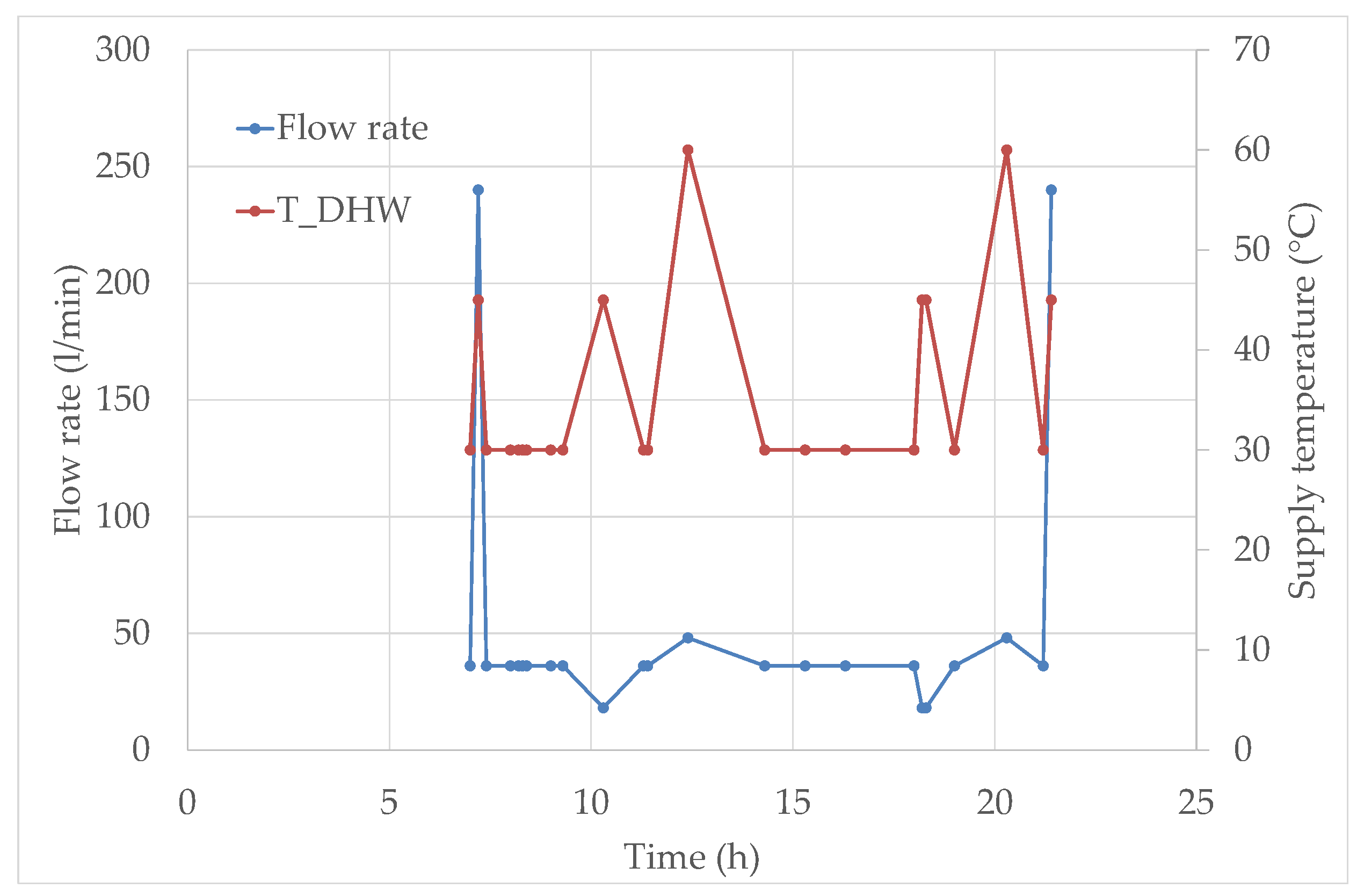
| DHW | domestic hot water |
| DNI | direct normal irradiance |
| E | energy |
| ɛ | ORC efficiency |
| el | electric |
| F | geographical factor |
| GHI | global horizontal irradiance |
| IMS | Innova MicroSolar |
| LFR | linear Fresnel reflector |
| m | mechanical |
| condenser flow rate | |
| organic fluid flow rate | |
| Ƞ | Efficiency |
| ORC | organic Rankine cycle |
| P | power |
| PCM | phase change material |
| PE | primary energy |
| PTC | parabolic through collector |
| SH | space heating |
| TES | thermal energy storage |
| th | thermal |
| tot | total |
| trad | traditional |
| Δhe | actual specific enthalpy variation across the expander |
| Δhp | actual specific enthalpy variation across the pump |
| z | zenith angle |
References
- EU (European Union). Energy Efficiency-Buildings. Available online: https://ec.europa.eu/energy/en/topics/energy-efficiency/buildings (accessed on 14 September 2018).
- EU (European Union). 2020 Energy Strategy. Available online: https://ec.europa.eu/energy/en/topics/energy-strategy-and-energy-union/2020-energy-strategy (accessed on 14 September 2018).
- EU (European Union). Energy 2020. A Strategy for Competitive, Sustainable and Secure Energy. Available online: https://eur-lex.europa.eu/legal-content/EN/TXT/PDF/?uri=CELEX:52010DC0639&from=EN (accessed on 14 September 2018).
- Kemna, R.; van Elburg, M. Heat from Renewable Energy Sources. The RES-H Initiative and Related Directives. VHK nr. 332, 5 September 2002. Available online: https://ec.europa.eu/clima/sites/clima/files/eccp/second/docs/renewable_energy_srcs_heat_en.pdf (accessed on 14 September 2018).
- Aboelwafa, O.; Fateen, S.E.K.; Soliman, A.; Ismail, I.M. A review on solar Rankine cycles: Working fluids, applications and cycle modifications. Renew. Sustain. Energy Rev. 2018, 82, 868–885. [Google Scholar] [CrossRef]
- Quoilin, S.; Orosz, M.; Hemond, H.; Lemort, V. Performance and design optimization of a low-cost solar organic Rankine cycle for remote power generation. Sol. Energy 2011, 85, 955–966. [Google Scholar] [CrossRef]
- Cioccolanti, L.; Tascioni, R.; Bocci, E.; Villarini, M. Parametric analysis of a solar Organic Rankine Cycle trigeneration system for residential applications. Energy Convers. Manag. 2018, 163, 407–419. [Google Scholar] [CrossRef]
- He, Y.-L.; Mei, D.-H.; Tao, W.-Q.; Yang, W.-W.; Liu, H.-L. Simulation of the parabolic trough solar energy generation system with Organic Rankine Cycle. Appl. Energy 2012, 97, 630–641. [Google Scholar] [CrossRef]
- Kumar, V.; Shrivastava, R.L.; Untawale, S.P. Fresnel lens: A promising alternative of reflectors in concentrated solar power. Renew. Sustain. Energy Rev. 2015, 44, 376–390. [Google Scholar] [CrossRef]
- Innova-Microsolar. Available online: http://innova-microsolar.eu/ (accessed on 14 September 2018).
- Pereira, J.S.; Ribeiro, J.B.; Mendes, R.; Vaz, G.C.; André, J.C. ORC based micro-cogeneration systems for residential application—A state of the art review and current challenges. Renew. Sustain. Energy Rev. 2018, 92, 728–743. [Google Scholar] [CrossRef]
- Dentice d’Accadia, M.; Sasso, M.; Sibilio, S.; Vanoli, L. Micro-combined heat and power in residential and light commercial applications. Appl. Therm. Eng. 2003, 23, 1247–1259. [Google Scholar] [CrossRef]
- Fubara, T.C.; Cecelja, F.; Yang, A. Modelling and selection of micro-CHP systems for domestic energy supply: The dimension of network-wide primary energy consumption. Appl. Energy 2014, 114, 327–334. [Google Scholar] [CrossRef]
- Mago, P.J.; Luck, R. Evaluation of the potential use of a combined micro-turbine organic Rankine cycle for different geographic locations. Appl. Energy 2013, 102, 1324–1333. [Google Scholar] [CrossRef]
- Kopper-Geiger Climatic Classification, 2018. Available online: http://koeppen-geiger.vu-wien.ac.at/present.htm (accessed on 27 October 2018).
- Entranze Project. Overview of the eU-27 Building Policies and Programs. Cross-Analysis on Member-States’ Plans to Develop Their Building Regulations towards the Nzeb Standard. Available online: http://www.entranze.eu/files/downloads/D5_1_3/ENTRANZE_Integration_of_report_D5.1_D5.2_D5.3_final.pdf (accessed on 14 September 2018).
- European Union. Building Database. Available online: https://ec.europa.eu/energy/en/eu-buildings-database (accessed on 14 September 2018).
- Oulu University of Applied Science. Rules and Regulations for Energy Performance in Buildings in Sweden. Available online: https://www.oamk.fi/hankkeet/ieeb/docs/materials/bc_material4.pdf (accessed on 14 September 2018).
- Kingspan. Building Regulation. Available online: https://www.kingspan.com/gb/en-gb/products/insulation/kingspan-insight/building-regulations (accessed on 14 September 2018).
- Coma, J.; Maldonado, J.M.; De Gracia, A.; Gimbernat, T.; Botargues, T.; Cabeza, L.F. Benchmarking of Energy Demand of Residential Buildings. In Proceedings of the 14th International Conference on Energy Storage (Enerstock 2018), Adana, Turkey, 25–28 April 2018. [Google Scholar]
- Elianto, S.R.L. Cagliari, Italy, 2018. Available online: http://www.eliantocsp.it/index.php/en/ (accessed on 14 September 2018).
- Enogia, Marseille, France, 2018. Available online: http://www.enogia.com/ (accessed on 14 September 2018).
- 3MTM NovecTM 649 Engineered Fluid. Available online: https://multimedia.3m.com/mws/media/569865O/3mtm-novectm-649-engineered-fluid.pdf (accessed on 14 September 2018).
- Northumbria University | Newcastle Upon Tyne | Study in the Best Student City. Available online: https://www.northumbria.ac.uk/ (accessed on 14 September 2018).
- Maldonado, J.M.; Fullana-Puig, M.; Martin, M.; Solé, A.; Fernández, A.G.; de Gracia, A.; Cabeza, L.F. Phase change materials for thermal energy storage at high temperature range between 201 °C and 270 °C. Energies 2018, 11, 861. [Google Scholar] [CrossRef]
- Serrano-López, R.; Fradera, J.; Cuesta-López, S. Molten salts database for energy applications. Chem. Eng. Process. 2013. [Google Scholar] [CrossRef]
- Thermacore, Northumberland, UK, 2018. Available online: http://www.thermacore-europe.com/ (accessed on 14 September 2018).
- Gantenbein, P.; Jaenig, D.; Kerskes, H.; Van Essen, M. Final Report of Subtask B; Chemical and Sorption Storage; The Overview a Report of IEA Solar Heating and Cooling Programme-Task 32 Advanced Storage Concepts for Solar and Low Energy Buildings Report B7 of Subtask B 2008. Available online: http://task32.iea-shc.org/Data/Sites/1/publications/task32-b7.pdf (accessed on 14 September 2018).
- Cioccolanti, L.; Tascioni, R.; Arteconi, A. Mathematical modelling of operation modes and performance evaluation of an innovative small-scale concentrated solar Organic Rankine Cycle plant. Appl. Energy 2018, 221, 464–476. [Google Scholar] [CrossRef]
- S.TRA.TE.G.I.E. srl, Società di Trasferimento Tecnologico e Guida all’Innovation Engineering, Ancona, Italy, 2018. Available online: http://www.strategiesrl.com/eng/Default.aspx (accessed on 14 September 2018).
- TRNSYS: Transient System Simulation Tool. Thermal Energy System Specialists, LLC, 22 North Carroll Street, Suite 370, Madison, WI 53703. Available online: http://www.trnsys.com/ (accessed on 14 September 2018).
- Meteonorn, 2018. Available online: https://www.meteonorm.com/ (accessed on 14 September 2018).
- Arteconi, A.; Del Zotto, L.; Tascioni, R.; Mahkamov, K.; Underwood, C.; Cabeza, L.F.; de Gracia, A.; Pili, P.; Mintsa, A.C.; Bartolini, C.M.; et al. Simulation analysis of an innovative micro-solar 2kWe Organic Rankine Cycle plant coupled with a multi-apartments building for domestic hot water supply. In Proceedings of the 10th International Conference on Applied Energy (ICAE2018), Hong Kong, China, 22–25 August 2018. [Google Scholar]
- prEN 15316-3-1. Heating Systems in Buildings—Method for Calculation of System Energy Requirements and System Efficiencies—Part 3-1 Domestic Hot Water Systems, Characterisation of Needs (Tapping Requirements) Prepared by Technical Committee CEN/TC228. Available online: http://www.cres.gr/greenbuilding/PDF/prend/set3/WI_11_TC-approval_version_prEN_15316-3-1_Domestic_hot_water-Characterization_of_needs.pdf (accessed on 14 September 2018).
- Enerdata, 2014. Average Electricity Consumption per Electrified Household. Available online: https://wec-indicators.enerdata.net/household-electricity-use.html (accessed on 14 September 2018).
- Villarini, M.; Arteconi, A.; Tascioni, R.; Cioccolanti, L. Modelling of two small-scale solar Organic Rankine Cycle trigeneration systems and comparison of their thermodynamic performance. In Proceedings of the SDEWES 2018, Palermo, Italy, 30 September–4 October 2018. [Google Scholar]
- Eurostat 2018. Electricity Prices for Household Consumers (Taxes Included), Second Half 2017 (EUR per kWh). Available online: https://ec.europa.eu/eurostat/statistics-explained/index.php/Electricity_price_statistics (accessed on 14 September 2018).
- Eurostat 2018. Gas Price by Type of User. Available online: https://ec.europa.eu/eurostat/tgm/table.do?tab=table&init=1&language=en&pcode=ten00118&plugin=1 (accessed on 14 September 2018).


| EU Region | Country | City | DNI (kWh/m2) | GHI (kWh/m2) | DNI/GHI (kWh/m2) | DNI∙cos(z) |
|---|---|---|---|---|---|---|
| South | Spain | Santander | 1008 | 1706 | 0.59 | 592 |
| South | Italy | Ancona | 1174 | 1876 | 0.63 | 684 |
| Central | France | Paris | 793 | 1411 | 0.56 | 503 |
| Central | Germany | Hamburg | 758 | 1325 | 0.57 | 467 |
| North | UK | Finningley | 597 | 1219 | 0.49 | 409 |
| North | Sweden | Stockholm | 1027 | 1531 | 0.67 | 521 |
| Country | External Walls | Roof | Floor | Windows |
|---|---|---|---|---|
| Spain | 0.74 | 0.46 | 0.62 | 3.1 |
| Italy | 0.34 | 0.32 | 0.30 | 2.0 |
| France | 0.36 | 0.20 | 0.22 | 2.1 |
| Germany | 0.28 | 0.20 | 0.30 | 1.3 |
| UK | 0.28 | 0.16 | 0.22 | 2.0 |
| Sweden | 0.18 | 0.15 | 0.15 | 1.2 |
| Technical SPECIFICATION | Innova MicroSolar |
|---|---|
| Electrical Power Production | 2 kWel |
| Heating Capacity | 18–20 kWth |
| Electrical Efficiency | 10–12% |
| Thermal Efficiency | 80% |
| Operational life | ≈25,000 h |
| Specific Power | 0.05 kWel/kg; 21 kWel/m3 |
| Orientation | Height (m) | External Surface (m2) | Windows (m2) | ||
|---|---|---|---|---|---|
| Single Dwelling | Terraced House | Single Dwelling | Terraced House | ||
| North | 2.7 | 27 | 108 | 3.10 | 12.4 |
| South | 2.7 | 27 | 108 | 3.10 | 12.4 |
| East | 2.7 | 27 | 27 | 3.10 | - |
| West | 2.7 | 27 | 27 | 3.10 | - |
| Location | Thermal Energy (kWh/year) | Electric Energy (kWh/year) |
|---|---|---|
| Santander (ES) | 27,565 | 2708 |
| Ancona (IT) | 34,098 | 3357 |
| Paris (FR) | 18,992 | 1869 |
| Hamburg (DE) | 17,550 | 1746 |
| Finningley (UK) | 14,041 | 1367 |
| Stockholm (SE) | 23,206 | 2294 |
| City | D_SH (kWh) | D_DHW (kWh) | D_el (kWh) | E_boiler (kWh) | Waste | Cov_el | Cov_th | Cov_tot |
|---|---|---|---|---|---|---|---|---|
| Santander | 4765 | 2013 | 3944 | 1899 | 82% | 69% | 72% | 71% |
| Ancona | 3997 | 2013 | 2432 | 1848 | 87% | 138% | 69% | 78% |
| Paris | 5645 | 2013 | 5036 | 3749 | 82% | 37% | 51% | 46% |
| Hamburg | 6458 | 2013 | 3079 | 5040 | 82% | 57% | 40% | 45% |
| Finningley | 5541 | 2013 | 3941 | 4034 | 79% | 35% | 47% | 43% |
| Stockholm | 6478 | 2013 | 7752 | 5314 | 86% | 30% | 37% | 34% |
| City | D_SH (kWh) | D_DHW (kWh) | D_el (kWh) | E_boiler (kWh) | Waste | Cov_el | Cov_th | Cov_tot |
|---|---|---|---|---|---|---|---|---|
| Santander | 11,727 | 8050 | 15,776 | 8719 | 51% | 17% | 56% | 39% |
| Ancona | 9678 | 8050 | 9728 | 7742 | 63% | 35% | 56% | 49% |
| Paris | 14,749 | 8050 | 20,144 | 15,003 | 50% | 9% | 34% | 23% |
| Hamburg | 17,782 | 8050 | 12,316 | 18,795 | 51% | 14% | 27% | 23% |
| Finningley | 13,861 | 8050 | 10,910 | 15,168 | 44% | 9% | 31% | 22% |
| Stockholm | 19,754 | 8050 | 31,008 | 20,302 | 57% | 7% | 27% | 17% |
| City | PE_trad (kWh) | PE_IMS (kWh) | Variation_PE % | Cost_trad € | Cost_IMS € | Variation_cost |
|---|---|---|---|---|---|---|
| Santander | 16,022 | 1680 | 70% | 1279 | 387 | 70% |
| Ancona | 11,544 | 1680 | 85% | 895 | 118 | 87% |
| Paris | 19,552 | 11,325 | 42% | 1351 | 788 | 42% |
| Hamburg | 15,398 | 7915 | 49% | 1394 | 680 | 51% |
| Finningley | 16,720 | 10,102 | 40% | 1071 | 661 | 38% |
| Stockholm | 27,099 | 18,475 | 32% | 2486 | 1677 | 33% |
| City | PE_trad (kWh) | PE_IMS (kWh) | Variation_PE | Cost_trad € | Cost_IMS € | Variation_cost |
|---|---|---|---|---|---|---|
| Santander | 57,421 | 40,596 | 29% | 4670 | 3403 | 27% |
| Ancona | 40,438 | 22,965 | 43% | 3178 | 1833 | 42% |
| Paris | 71,087 | 59,326 | 17% | 4950 | 4161 | 16% |
| Hamburg | 54,274 | 43,512 | 20% | 5130 | 4216 | 18% |
| Finningley | 59,330 | 49,782 | 16% | 3930 | 3383 | 14% |
| Stockholm | 102,798 | 90,240 | 12% | 9266 | 7981 | 14% |
© 2018 by the authors. Licensee MDPI, Basel, Switzerland. This article is an open access article distributed under the terms and conditions of the Creative Commons Attribution (CC BY) license (http://creativecommons.org/licenses/by/4.0/).
Share and Cite
Arteconi, A.; Del Zotto, L.; Tascioni, R.; Mahkamov, K.; Underwood, C.; Cabeza, L.F.; Maldonado, J.M.; Manca, R.; Mintsa, A.C.; Bartolini, C.M.; et al. Multi-Country Analysis on Energy Savings in Buildings by Means of a Micro-Solar Organic Rankine Cycle System: A Simulation Study. Environments 2018, 5, 119. https://doi.org/10.3390/environments5110119
Arteconi A, Del Zotto L, Tascioni R, Mahkamov K, Underwood C, Cabeza LF, Maldonado JM, Manca R, Mintsa AC, Bartolini CM, et al. Multi-Country Analysis on Energy Savings in Buildings by Means of a Micro-Solar Organic Rankine Cycle System: A Simulation Study. Environments. 2018; 5(11):119. https://doi.org/10.3390/environments5110119
Chicago/Turabian StyleArteconi, Alessia, Luca Del Zotto, Roberto Tascioni, Khamid Mahkamov, Chris Underwood, Luisa F. Cabeza, Jose Miguel Maldonado, Roberto Manca, André C. Mintsa, Carlo M. Bartolini, and et al. 2018. "Multi-Country Analysis on Energy Savings in Buildings by Means of a Micro-Solar Organic Rankine Cycle System: A Simulation Study" Environments 5, no. 11: 119. https://doi.org/10.3390/environments5110119
APA StyleArteconi, A., Del Zotto, L., Tascioni, R., Mahkamov, K., Underwood, C., Cabeza, L. F., Maldonado, J. M., Manca, R., Mintsa, A. C., Bartolini, C. M., Gimbernat, T., Botargues, T., Halimic, E., & Cioccolanti, L. (2018). Multi-Country Analysis on Energy Savings in Buildings by Means of a Micro-Solar Organic Rankine Cycle System: A Simulation Study. Environments, 5(11), 119. https://doi.org/10.3390/environments5110119