Article

Drinking Water and Sanitation Safety Planning for Medical Facilities: An Innovative PoU Approach for a Water System Description Using Ecomaps

1
Institute for Hygiene and Public Health, Medical Faculty, University of Bonn, 53127 Bonn, Germany
2
Department of Microbiology and Hospital Hygiene, Bundeswehr Central Hospital Koblenz, 56072 Koblenz, Germany
3
Lower Saxonian State Health Authority, 30449 Hannover, Germany
*
Author to whom correspondence should be addressed.
Environments 2025, 12(7), 217; https://doi.org/10.3390/environments12070217
Submission received: 2 May 2025 / Revised: 22 June 2025 / Accepted: 24 June 2025 / Published: 26 June 2025

Abstract

Drinking Water Safety Plans (DWSP) in buildings serve to identify health hazards associated with the drinking water system. Sanitation Safety Plans (SSP) fulfill the same purpose for the sewage system. Water Safety Plans (WSP) include DWSPs, SSPs, and water systems like gray water and firefighting water. WSPs are based on a high-quality description of the water systems. This paper presents a new methodology for describing water systems. In contrast to previous approaches, the system description begins at the point where the water is consumed. These points of use are described using ecomaps, which are then supplemented with information about the pipe network. This approach makes it possible to fulfill four relevant premises: (1) the system description includes all essential parts of the drinking water installation, (2) the system description is possible with usual equipment, (3) the system description can be carried out with the least possible additional personnel costs, and (4) the system description is controllable, versionable, changeable, and forgery-proof. The ecomaps created in this way are suitable for the next step within the WSP framework, namely hazard and risk assessment. In addition, the ecomaps can be integrated into a quality, occupational safety, or environmental management system. Aspects of water security can be added to enable the ecomaps to be used as the basis for a total integrated water management system.

1. Introduction

The right to water and sanitation has been an internationally recognized human right since 2010 at the latest; it is “is essential for the full enjoyment of life and all human rights” [1]. Drinking water is “is the most important nutrient. It cannot be substituted” [2]. In 2015, the 17 “Sustainable Development Goals” (SDG) of the United Nations were formulated to improve the world in various areas by 2023 [3]. SDG 3 refers to “good health and well-being” [4], while SDG 6 refers to “clean water and sanitation” [5]. However, only 73% of the world’s population currently has access to clean drinking water, and if efforts to achieve this goal do not increase sixfold, 2 billion people will still live without safely managed drinking water in 2030 [6].
The minimum hygiene requirements for drinking water worldwide are described in the “Guidelines for drinking-water-quality” of the World Health Organization that were first published in 1978 [7]. The original approach was to monitor the outcome quality using reference or limit values that had to be complied with in drinking water samples. Since 2004, a new approach has been introduced to monitor structural and process quality in order to ensure drinking water quality. This approach is called “Water Safety Planning” (WSP) and corresponds to a structured risk management for drinking water [8]. In 2015, the WSP approach was supplemented by the complementary approach of “Sanitation Safety Planning” (SSP) [9]. In this paper, WSP is used as a generic term and includes drinking water, process water, gray water, firefighting water, sewage, and other types of water. For specific aspects of drinking water, the term “drinking water safety plan” (DWSP) is used, and for specific aspects of sewage, the term SSP is used.
The DWSP approach covers the entire drinking water cycle “from catchment to consumer” [10]. It is possible that responsibility for the drinking water system and thus also for the DWSP changes over this cycle. This is often the case where drinking water enters buildings, where responsibility passes to the building operator. Therefore, a modified methodology for creating a WSP “from point-of-entry (PoE) to point-of-use (PoU)” was developed for the building operators [11] and has since been applied in several projects [12,13,14,15]. The SSP approach covers mirror-inverted the entire sewage cycle from consumer to back catchment. Responsibility for sewage can also change, especially when it leaves buildings and enters the public sewage system. The framework for a DWSP and an SSP in buildings is shown in Figure 1.
The “Description of the water system” is the first step a WSP team takes in preparing for a WSP. All further steps are based on this system description, which is why it should be carried out to a high-quality standard. It is therefore surprising that little information is available on the exact implementation of a system description. It should
  • “document all components of the building water systems, including PoE and PoU treatment, distribution systems (e.g., hot water, cold water, firefighting), water-using devices (e.g., swimming pools, cooling towers) and specific water uses”;
  • “[identify] the uses of each type of water”;
  • “follow the delivery of water from PoE to all points of delivery or use within the building” [11].
While these generic specifications may be sufficient for the creation of WSP in small, simple buildings [12], they are not practical for more demanding buildings, such as hospitals, for three reasons. First, hospitals have a complex water system in which not only drinking water but also other types of water (e.g., firefighting water, process water for the reprocessing of medical devices or the production of blood products or pharmaceuticals) are used [11]. Second, patients are more susceptible to facultative or opportunistic pathogens because their immune system may be weakened by illness (e.g., swallowing disorders, immunosuppression) or treatment (e.g., antibiotics, proton pump inhibitors, or catheters or other devices) [16]. Third, hospitals often consist of several buildings that were constructed in different years, some of which have been repeatedly converted or repaired, and for which only rudimentary documentation may be available.
Our aim was therefore to develop a methodology that would make it possible to practically implement the system description of large and complex water systems, such as those found in hospitals. Our hypothesis was that the risk from contaminated drinking water materializes where the water is used. At the same time, the PoU is the part of the drinking water system that can be identified by inspection without additional information. That is why we have not built the system description from the PoE but from the PoU.

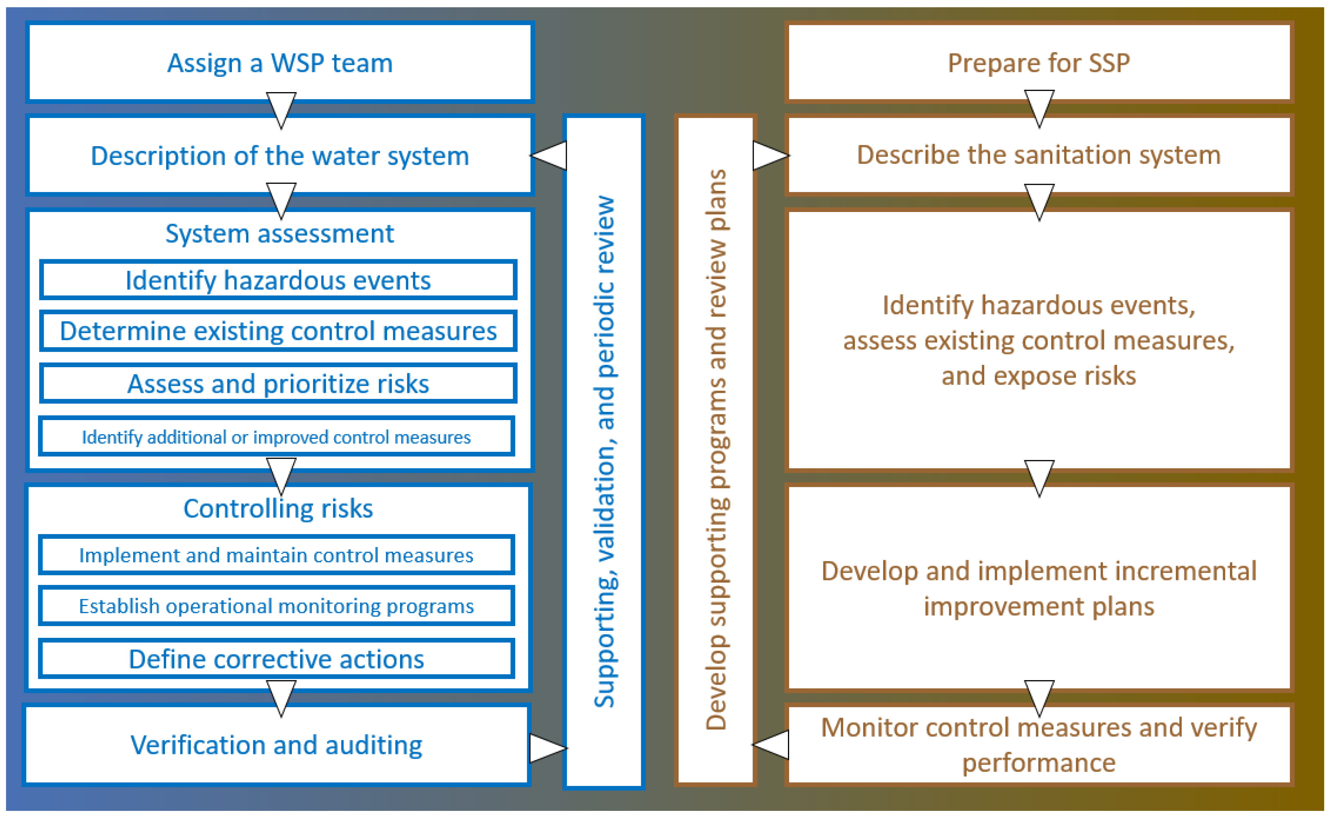
2. Materials and Methods

Our developed methodology is based on ecomapping, i.e., the visualization of (environmental) information on a map. The ecomap “Water Use and Wastewater System” from the European Commission’s publication “EMAS “easy” for Small and Medium Enterprises” was taken as a starting point and systematically developed for the requirements of a WSP [17].

2.1. Premises

The following conditions should be met:
  • The system description should include all essential parts of the drinking water installation;
  • The system description should be possible with the usual equipment (no—expensive—software or hardware);
  • The system description should be carried out with the least possible additional personnel costs;
  • The system description should be controllable, versionable, changeable, and forgery-proof;
“Essential parts” of the water system are
  • all PoU in rooms in which patients or non-technical staff are regularly present;
  • all PoU water systems that communicate directly or indirectly with the drinking water installation;
  • all cold and warm water pipes as well as sewage pipes and pipes for other types of water, if appropriate.
“Usual equipment” is pen and paper, as well as computers with commonly used operating systems (Microsoft Windows, Apple macOS, or Linux) and office suites (Microsoft Office, OnlyOffice, LibreOffice, …).
“Least possible additional personnel costs” refers to the fact that no additional personnel should be hired to create the plans, nor is it necessary to outsource the work. The training required for personnel should also be kept to a minimum. In this study, the plans were drawn up by hospital hygiene staff, but this can also be carried out by technical staff, environmental, occupational safety and quality management personnel, or other relevant personnel.
“Controllable, versionable, changeable, and forgery-proof” are properties resulting from the requirements of quality management systems such as ISO 9001 [18].

2.2. On-Site Inspection
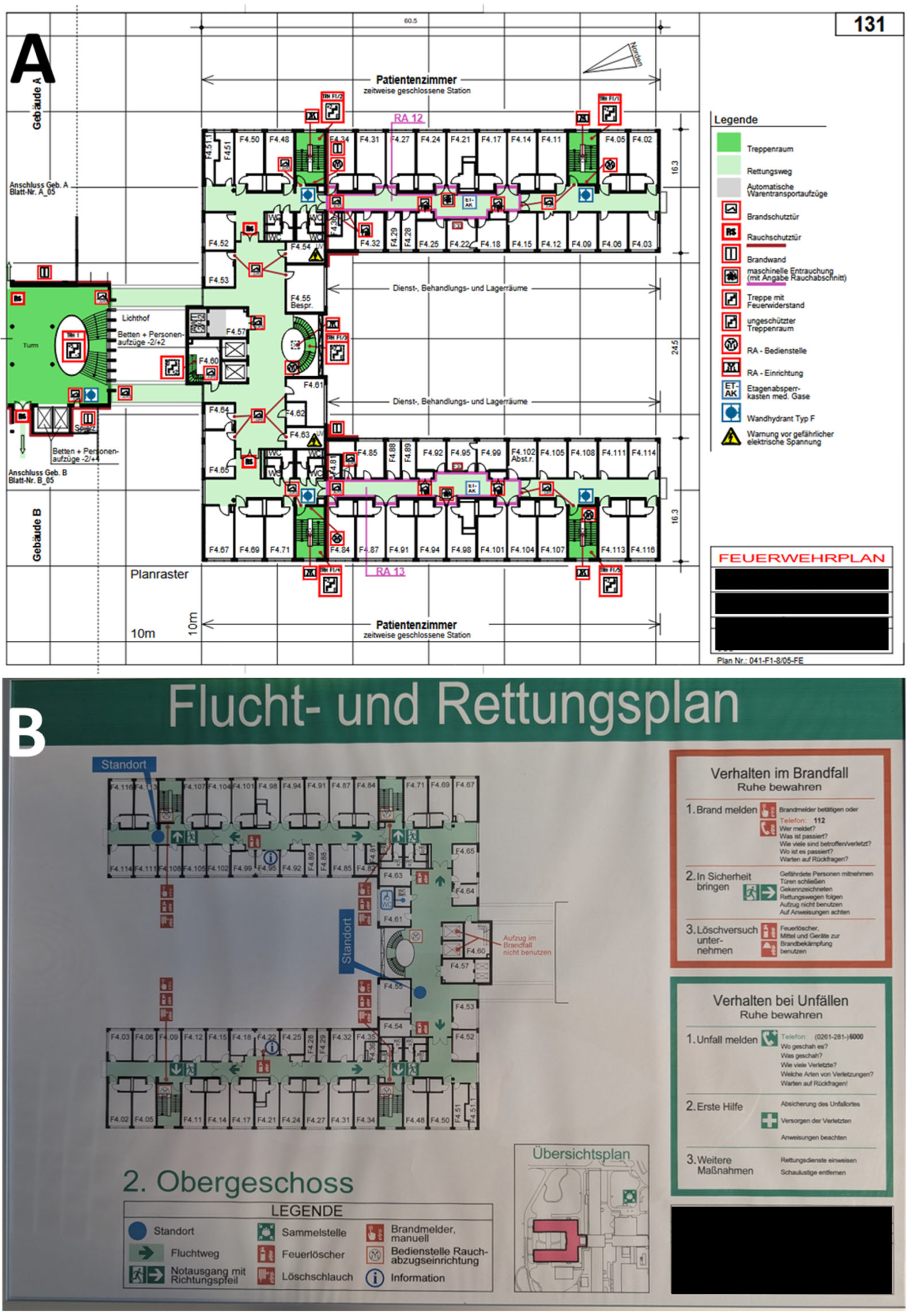
The data collection was achieved via an on-site inspection, during which each room was examined for points of contact with the drinking water or sewage system. In accordance with premises 2 and 3, only paper plans on a clipboard and pens were used to generate paper ecomaps. In order to eliminate inter-user variability as far as possible, the inspection was carried out by two people, each of whom created their own paper ecomap. The remaining steps were then carried out by one person. Finally, after the PDF had been created, the result was validated by comparing it with the paper ecomap of the second person and checked for discrepancies.

2.2.1. Plans

In the official WHO documents, hand-drawn or computer-based sketches are used as the basis for WSP [11,19]. For the published implementation guidelines of WSP, sketches also usually serve as the basis for the system description [20,21]. However, sketches are not suitable for a professional WSP in medical facilities. They do not have to be to scale, nor are they easy to update or reproduce, which is why they are more suitable for use in emergency medicine and disaster management [22].
It therefore makes sense to use professional plans, which ideally should already exist to meet premise 2. At first glance, the use of construction plans seems obvious, since these—at least within the European Union [23]—must be produced for every construction project. However, international standards also exist for construction plans [24]. But even blueprints have disadvantages: on the one hand, they are no longer updated after construction is complete, and on the other hand, they contain a lot of information that is useless for the WSP, which is why they are often printed on large paper formats (DIN A0 or A1 [25]).
In Germany, there are plans that do not have these disadvantages: fire brigade plans according to the German standard DIN 14095 [26] (Figure 2A). These are often mandatory for hospitals, as enforced by local fire safety authorities, and therefore meet premise 2. The following requirements apply to fire brigade plans:
  • They must be prepared by a suitably qualified person.
  • They must be reviewed and updated every two years.
  • They must be based on a 10 × 10-m grid.
  • They must be printable on A3- or A4-sized paper [25].
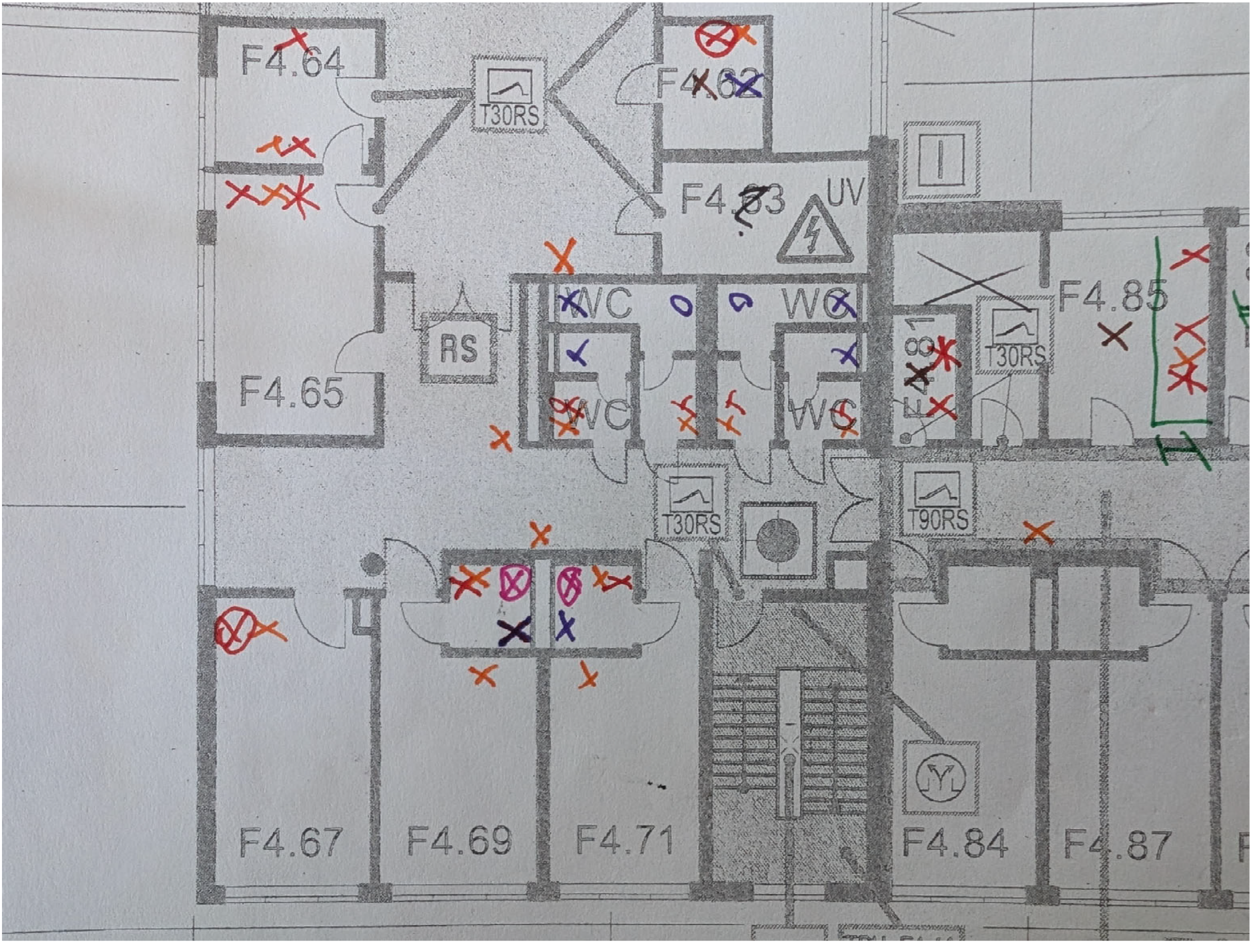
Fire brigade plans therefore provide a good basis for creating a WSP and were used on DIN A3-sized paper as part of our methodology. Escape and rescue plans in accordance with ISO 23601 [27] (Figure 2B) represent a significantly less detailed but globally standardized alternative. However, other plans that fulfill the requirements described can also be used with this methodology.

2.2.2. Pens

Thin felt-tip pens in bright colors are best used on A3-sized paper plans. For the work presented, we used a Stabilo (Schwan-Stabilo GmBH, Heroldsberg, Germany) fineliner, model Point 88, with a line width of 0.4 mm. These are available in 65 different colors, although to achieve a good distinctiveness, significantly fewer colors can be used (Figure 3). Other pen models from other manufacturers can also be used if premise 2 would otherwise be violated.
The number of colors required depends on the size of the coding system, which is less extensive for smaller medical facilities such as a GP practice than for a large hospital.

2.2.3. Coding System

The coding system was developed to enable a graphical representation of the various PoU elements and the piping systems. It is based on the principles of the system of tactical signs used in the military and in disaster control [28]. The coding system should
  • Be logical and unambiguous;
  • Be simple and as self-explanatory as possible;
  • Be presentable with simple symbols;
  • Be presentable both with and without electronic IT tools;
  • Be designed in such a way that it can be adapted and expanded;
  • Enable a presentation of the most important information that is appropriate;
  • Be suitable as a basis for cooperation within and between medical facilities.
Figure 4 shows the structure of the coding system using the example of taps. A blue cross (X) is used for a tap at a washbasin in a cold-water system, and a red cross (X) is used for a tap at a washbasin in a hot-water system. An automatic flushing device is represented by a circle (O), and a sampling valve by a square (□), each in blue or red. The Plus (+) or Diamant (◊) forms are not used due to possible confusion. The symbols can be combined: if a tap at a washbasin is equipped with an automatic flushing system, the cross is surrounded by a circle; if the tap at a washbasin has been designated as a sampling point, the cross is surrounded by a square. Taps at special basins, for example, at a sink in a cleaning agent room, can be identified with simple additions to the basic symbol, such as a horizontal line through the cross. The full coding system is shown in Figure S1.

2.2.4. Attachment Sheets

It seems impossible to represent every conceivable PoU with the coding system; this is neither intended nor necessary. Instead, the coding system should cover the 80% most important PoU according to the Pareto principle. For the remaining 20%, attachment sheets can then be added.
Figure 5 shows a system diagram that illustrates the PoU situation of a ward kitchen. To do this, a photo of the affected PoU is taken, copied into a document, and all relevant components are given a serial number and described. If deemed useful, the description can include the manufacturer, model name, year of manufacture, special features of cleaning and disinfection, maintenance information, and details of past incidents.

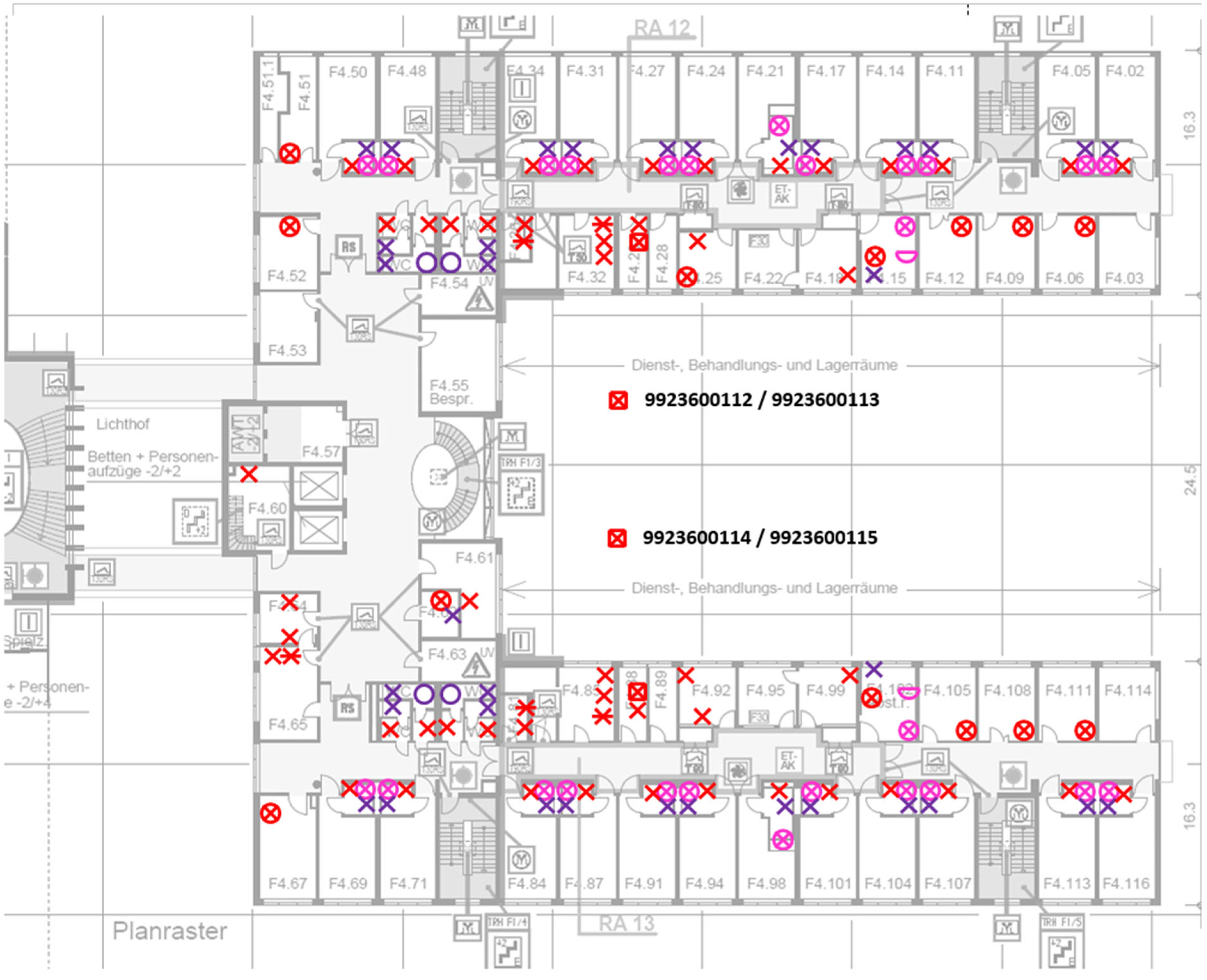
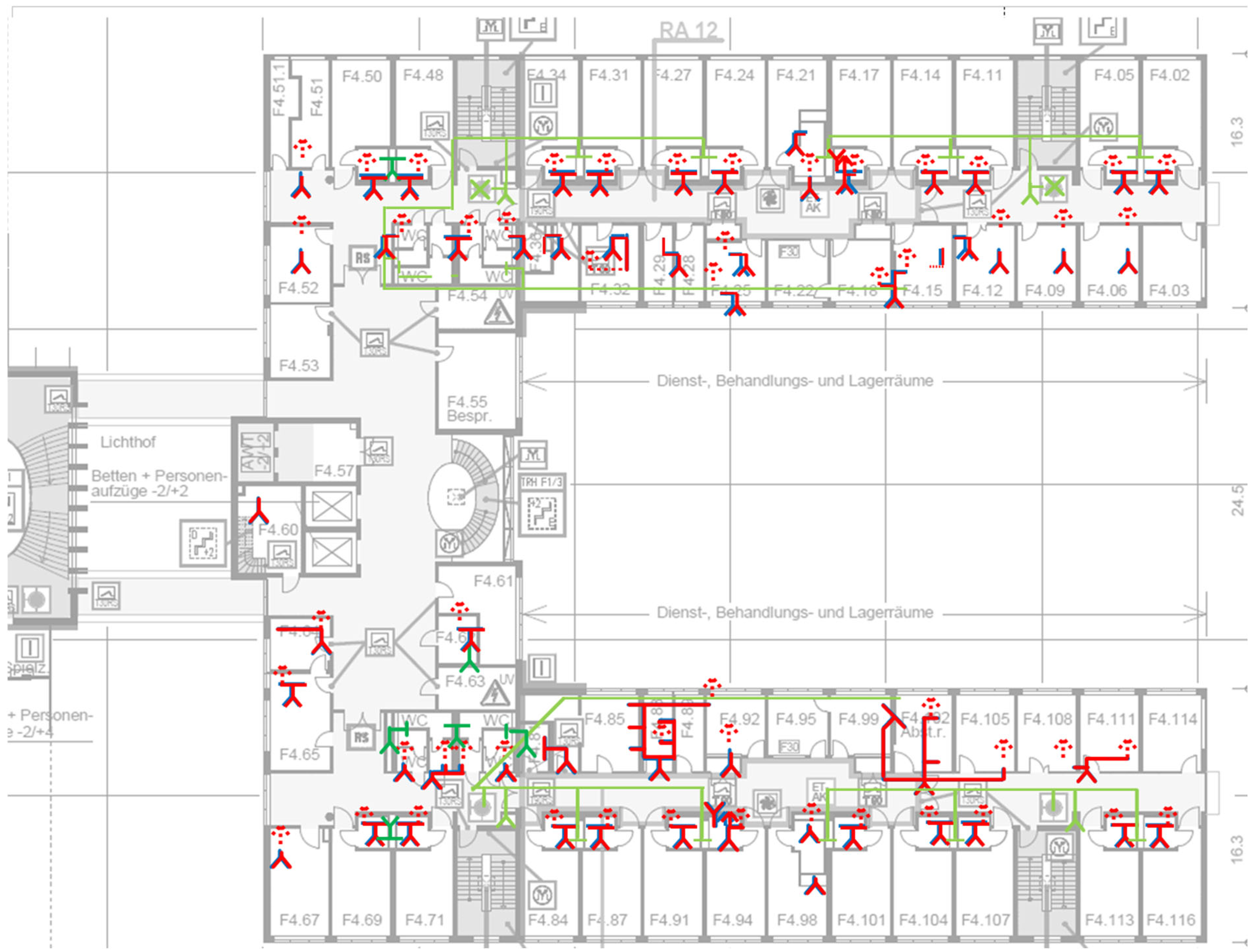
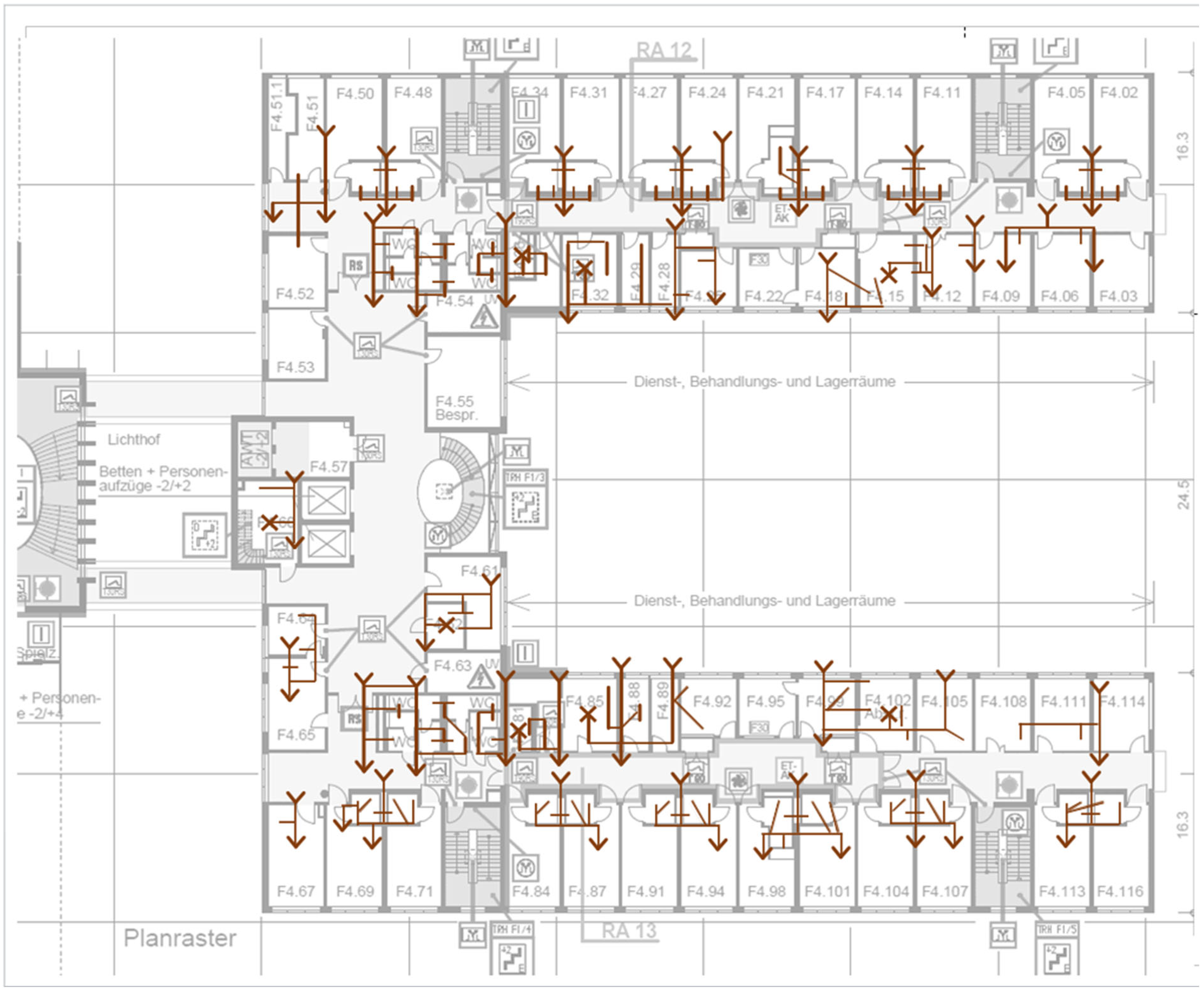
2.3. Transfer into Digital Ecomaps

For further processing, the paper ecomaps are transferred to a visualization or desktop publishing program. The important thing is that the program used can create layers and export them as a PDF. We used Microsoft Visio Professional 2021 (Microsoft Corp., Redmond, WA, USA) for this. To avoid violating premise 2, it is also possible to use the free program Scribus [29] in version 1.5.0 or higher (the current stable version is 1.6.3) or any other suitable program instead.
The program is set to DIN A3, and the used plans are used as the background layer. Then the various symbols are digitally drawn in, with each symbol type generally being given its own layer. By assigning the layers, it is possible to display only certain PoUs or to hide certain PoUs. In exceptional cases, several symbol types can be grouped in one layer, for example, all blue symbols from Figure 4 in a “cold water” layer.

2.3.1. Possible Extension Using a Schematic Pipe Diagram

Although schematic pipe diagrams are not always available, and for older buildings they are often no longer up to date, they should be incorporated into the digital ecomap if they are available to meet premise 1. Furthermore, missing or old piping and instrumentation diagrams should be added or revised, which, however, can cost time and money and thus violate premises 2 and 3. We have therefore only transferred the existing piping and instrumentation diagrams into our digital ecomap for our methodology.
Schematic pipe diagrams are usually shown in a side view. A special feature of the pipes is the fact that they can be routed across floors. Therefore, a special font must be introduced for this 3-dimensional pipe routing for the 2-dimensional representation on a floor plan. Water pipes that move within the plane are represented just by simple lines. Arrows in the appropriate direction (↓, ↑) are used for water pipes that continue downwards or upwards. Water pipes coming from above or below are represented by modified arrows with the arrowhead moved to the arrow nock.
Figure 6 shows the coding system for the different pipe systems. Cold drinking water (PWC) is shown in blue, while hot drinking water (PWH) is shown in red. The circulation line (PWH-C) is shown as a red dashed line. Sewage pipes are shown in brown, other water pipes in green, whereby a distinction can be made here between process or gray water (rainwater, cooling water, etc.) in dark green and firefighting water in light green, if necessary. The different pipes (PWC, PWH+PWH-C, sewage, process or gray water, and firefighting water) are each assigned to a layer.

2.3.2. PDF Generation

To preserve the layer properties when exporting to PDF, the visualization or desktop publishing program used must support at least PDF 1.5. Microsoft Visio can only retain layer properties during PDF export using an Adobe plug-in. This plug-in is only available for the 32-bit version of Microsoft Visio, which in turn can only be installed if a parallel installed version of Microsoft Office (in our case Microsoft Office LTSC Professional Plus 2021) is also installed in the 32-bit version. Scribus has been able to perform the corresponding PDF export in the 64-bit version since version 1.5.0. For other programs, the corresponding program documentation must be consulted to determine whether a PDF export with layer property preservation is possible.
The PDF export is necessary to fulfill premise 4. The created PDF can in turn be imported into a quality management system of the medical faculty to be controllable, versionable, and forgery-proof. Changeability is only possible via revision of the original files from the visualization or desktop publishing program with a new PDF generation afterwards.

2.4. Updates

In order to permanently fulfill premises 1 and 4, regular updates of the ecomaps are necessary, which, however, must not require additional personnel or material resources in order not to violate premises 2 and 3.
It is advisable to review and update the plans once a year and as required. Requirements arise primarily in connection with construction work, repairs, and incident management.
The most recent plan can be printed out, whereby it is advisable to only display the PoU layers. During a routine or ad hoc on-site inspection, real life can then be compared with the plan, and any deviations documented. These can then be inputted into the visualization or desktop publishing program as described above.
For major changes, such as new buildings or conversions, new plans are generated in accordance with the procedure described above on the basis of the new fire brigade plans. It is important that the WSP team is informed of such cases.

3. Results

We developed and tested the methodology at a maximum-care hospital with around 500 beds and approximately 1500 employees.
The methodology and coding system were developed in parallel with the pretest in an iterative process. The time required for the method development was approximately 30 h.
For the pretest, we used a relatively new F1 wing of the building that was commissioned in 2007. This part of the building consists of four floors (ground floor, first floor, second floor, and roof floor). Details on the use of the building are provided in Table 1. The time required for the pretest was approximately 25 h.
Figure 7 shows the second floor of the F1 wing. Rooms 4.01 to 4.65 belong to the psychiatric ward, while rooms 4.67 to 4.116 belong to the urology ward. The stations are set up in a mirror image. The ecomap shows all relevant PoU layers. According to Figure 4, red symbols represent water taps on washbasins with PWC and PWH (74 in total). A total of 13 washbasins are equipped with an automatic flushing device (17.6%). Two taps have sampling valves for drinking water samples (2.7%) with assigned identity numbers (992360011). Five washbasins are designed as sink basins in cleaning rooms or unclean workrooms (6.8%). Purple crosses (X) indicate toilets (35), while purple circles (O) indicate urinals (4). Urinals are located exclusively in staff and visitor restrooms. Pink crosses with a surrounding circle (⦻) indicate showers with automatic flushing devices (26), while pink tubs stand for bathtubs in ward bathrooms (2).
The fact that some washbasins and all showers are equipped with automatic flushing devices is immediately apparent on the ecomap.
Figure 8 shows the same level of the F1 wing; this time only the layers with the pipe systems are active: blue lines represent PWC, red lines represent PWH, dashed red lines represent PWH-C, dark green lines represent gray water (here: backwash water from the osmosis system), and light green lines represent firefighting water.
It becomes apparent that 11 toilets are operated using gray water (28.2%), while the other 28 toilets are operated using firefighting water (71.8%).
In addition, it can be seen that almost all PWC and PWH pipes come from the lower level and only supply a few PoUs. Relevant exceptions to this are room groups F4.85, F4.88, and F4.89, as well as room groups F4.99, F4.102, and F4.105, where the pipes supply more PoU.
Almost all washbasins have a PWH-C pipe, with the exception of the technical room, F4.60. It is noticeable that even washbasins with an automatic flush function have a PWH-C pipe, which indicates that these can only be used for flushing the PWC.
Our methodology can be easily extended to the sewage system. Figure 9 shows the second floor of our pre-test wing F1, in which the floor drains and sewage pipes are now displayed.
In addition to the drains from the sinks, showers, bathtubs, and toilets, there are a total of eight floor drains marked with brown crosses (X).
A further improvement to the sewage system description could be to draw lines of different thicknesses or darkness for the different diameters of the sewage pipes, for example, thin or light for DN50 (mainly sewage pipes from washbasins), medium for DN70 (mainly sewage pipes from showers, floor drains, and some downpipes), and thick or dark for DN90 or larger diameters (mainly sewage pipes from toilets and most downpipes).

4. Discussion

This study aimed to develop a methodology that would make it possible to practically implement the system description of large and complex water systems, such as those found in hospitals. We developed a methodology which, unlike previous approaches, does not start at the PoE and follow the path of the water but does exactly the opposite, starting at the PoU. The PoU can be identified without any additional tools during on-site inspections; at the same time, the risk posed by contaminated drinking water arises precisely at this point. Risk is thereby a function of a hazard, possible hazardous events, the probability that this hazard will manifest itself, and the impact that the manifestation of this hazard will have [30].
Comparably complex water systems, such as those found in hotels, office complexes, schools, airports, or large residential complexes, have not been explicitly investigated. However, the methodology presented here can also be applied in such cases if suitable plans for creating ecomaps are available. This is supported by the fact that the building types mentioned usually have fewer different types of water and less complex PoU. In hospitals, for example, in addition to drinking water and sewage, there is firefighting water, gray water, non-potable water for laboratories, pharmaceuticals or blood product manufacturing, and the processing of medical devices. This range of water qualities, types of use, and different PoUs is not found to this extent in other building types. It is therefore very likely that the methodology and coding system presented here can be applied to many other building types.

4.1. Hazards from Drinking Water

Hazards arising from drinking water systems in buildings, on the one hand, can be classified as biological or chemical hazards [11]; radiological hazards are also conceivable but will not be considered further here. On the other hand, they can be classified as hazards that enter the drinking water system from outside and hazards that arise within the drinking water system [11]. A DWSP in buildings primarily serves to detect biological and chemical hazards that arise within the drinking water system. In medical facilities, Pseudomonas aeruginosa and Legionella pneumophila are the most relevant pathogens associated with drinking water-related transmission and infections [16,31,32,33].
P. aeruginosa is mainly introduced into drinking water systems through poor hygiene during construction and maintenance work [34,35,36] or through components that are already contaminated by delivery. Regardless of whether the entire drinking water system is contaminated or only parts of it [35], regardless of whether it is a middle section [31,35] or the PoU of the drinking water system [31,33,37,38], the risk always materializes at the PoU of the drinking water system; that means at the patient [33,38]. P. aeruginosa forms biofilms in drinking water systems that are difficult to eradicate by disinfection [39,40], which is why the only effective measure is often to identify and remove contaminated components [34,35,41]. Ecomaps help in two ways: firstly, if the ecomaps are updated regularly and as needed during construction or maintenance work, as we recommend, contaminated components can be found more quickly by comparing the ecomaps for a given area over time. Secondly, if several PoUs are contaminated, ecomaps can be used to show or rule out a connection. For example, in our F1 wing, it is to be expected that contamination with P. aeruginosa would not spread within a single floor but across multiple floors. If multiple instances were detected on one floor, it would be necessary to assume a significantly larger or more central source of contamination. Ecomaps allow this connection to be identified immediately.
L. pneumophila enters the drinking water system via PoE and growths in pipes and taps with stagnation [42] when the water temperature is between 25 °C and 30 °C [43]. No growth occurs below 18 °C [43] or above 50 °C [42], and Legionella bacteria are killed at temperatures above 55 °C [42]. For buildings, a temperature of 60 °C is therefore recommended for PHW and at least 55 °C for PHW-C [44]. Due to climate change, Legionella bacteria are increasingly being found in cold water when it reaches temperatures above 20 °C or even 25 °C [45]. Ecomaps help prevent Legionella by identifying and documenting all PoUs so that they can be included in appropriate flushing programs, thereby preventing stagnation. In addition, the pipe network is displayed in ecomaps, showing the longest distances from the PoE to the PoU, so that PWC and PWH temperature measurements can be taken at these PoU.
Most chemical hazards are introduced into buildings from outside, which is why a DWSP for water suppliers is important [19,46,47,48]. A relevant exception is lead, which may be present in pipes or components of the drinking water system [49,50]. Lead (and other metals such as nickel or copper) can dissolve into drinking water when stagnant, with the concentrations achieved depending on factors such as the duration of stagnation [51]. Even the smallest components, such as lead-containing fittings, can cause the lead threshold value to be exceeded [49]. Here too, DSWP based on ecomaps can be useful in two ways: first, as with Legionella, they can help prevent stagnation by documenting all PoU and integrating them into appropriate flushing programs. Second, as with P. aeruginosa, they can help identify contaminated components within the drinking water system by correlating the results of sampling different PoUs with the pipe diagram.
The use of DWSP is recommended for the prevention of both Pseudomonas-associated infections and Legionella-associated infections [31,32,52] and is also rational for the prevention of lead exposure. Our methodology enables us to create a highly detailed and up-to-date system description, which can be used as a basis for a qualified hazard and risk analysis that can lead to appropriate risk management measures as recommended in the WSP framework for buildings [11]. Schmidt et al. [12] piloted WSPs in hospitals (and other building types), demonstrating the feasibility and benefits of WSP implementation at the institutional level. They found that introducing WSPs in premise plumbing systems led to increased system knowledge and awareness among building operators and improved the operation of the internal water system, therefore providing real-world evidence that implementing WSPs heightens operational awareness and oversight, even in facilities that already met technical standards. Taking into account the fact that many buildings do not fully comply with technical standards, as studies show, the positive effect is likely to be even greater. A meta-analysis from 2015, for example, found that 16.5% of the analyzed buildings in Germany have a deficiency in drinking water installations with regard to the technical measure value for legionella [53]. Between 2013 and 2017, with an average of 45 large drinking water plants reported annually, 81 new deviations from the technical standards per year were detected in Bremen, i.e., about 1.8 new deviations per plant per year [54], and it is likely that this will be similar for buildings. However, regular reviews of all PoU help to ensure that deviations are identified and recorded in a structured manner and that appropriate measures can be initiated.

4.2. Advantages of the PoU Approach

Both the WSP framework for water suppliers [55] and the WSP framework for buildings [11] provide for the system description to be created “from catchment to consumer” or “from PoE to PoU”. Whether this is the best way for water suppliers to describe a system will not be considered further here. But, for hospitals and other large buildings with complex drinking water installations, the opposite approach of starting at the PoU and working against the path of the water has at least three advantages.
The first advantage is that the system description starts where the risk materializes. Certain chemicals or biofilms may have a technical influence on drinking water or sanitation systems, but the health risk for the consumer arises at the PoU. This is because this is where the water leaves the drinking water system or where aerosol formation causes sewage-associated recontamination. The guiding principle known from emergency medicine, “treat what kills first” [56], applies analogously to a PoU approach.
The second advantage is that the PoU approach begins the system description at the “last mile”. In distribution logistics, this refers to the last part of the delivery route to the customer [57]. For drinking water in buildings, “last mile” refers to the PoU [58,59,60]. While the central drinking water system can be monitored in real-time effectively by technical staff using process controls, the PoU can hardly be monitored. However, the user is able to manipulate the PoU by connecting additional water-carrying devices or causing stagnation through non-use [11]. The PoU approach starts at the “last mile” and thus covers this otherwise unmonitorable area first.
The third advantage of the PoU approach is that it starts directly with the visible elements of the drinking water system, whereas PoE approaches often start with schematic pipe diagrams due to the lack of easy access to technical areas. This approach can lead to the system description being created solely on the basis of plans, rather than inspecting the conditions on site. But, speaking with Alfred Korzybski [61], “the map is not the territory”, because plans can be outdated or incorrect. The PoU approach starts without plans but with on-site inspection, which is then supplemented with plans as the process progresses.
In summary, the PoU approach represents a significantly more effective approach to describing water systems in buildings. In line with the Pareto principle, it captures the PoU completely within a short period of time. This means that the locations where risks materialize, which are difficult to monitor centrally and are not recorded in plans or are recorded incorrectly, form the basis of the system description. PoE approaches, on the opposite, invest a lot of time and energy in the description of the technical parts of the water system and piping before they even describe one single PoU, making them “anti-Pareto” by design. There is no comparable systematic PoE approach. However, future studies could develop such an approach and compare it with the PoU approach presented here in terms of effectiveness and efficiency.

4.3. Hazards from Sewage

Hazards in sewage can be classified according to their target: they can pose risks to patients or employees (social environment), risks to other water systems or the building infrastructure (technical environment), or risks to the natural environment.
For patients and employees of a hospital, sewage primarily poses a risk at the PoU. The health risks arise from the presence of facultative pathogenic bacteria in the sewage system, which often develop resistance due to intensive contact with antibiotic residues [62,63,64,65,66]. Clinically relevant bacterial species here are known as the “ESCAPEE” group [67,68]: Enterococcus faecium, Staphylococcus aureus, Klebsiella pneumoniae, Acinetobacter baumannii, P. aeruginosa, Enterobacter spp., and Escherichia coli. Depending on their resistance, infections caused by these bacteria can be among the most difficult to treat [69]. Transmission to patients and staff can occur directly, through inhalation of sewage aerosols, or indirectly, through contamination of hands, medicines, or medical devices. Ecomaps can be used in conjunction with process observations to identify these indirect transmission routes. In addition, ecomaps can provide an impression of the amount of PoU present at a ward in order to identify PoU that can be removed to completely eliminate the risk of transmission.
Water systems or the building infrastructure can be endangered by sewage if there are undetected pipe breaks, and sewage enters other water systems as a result. Other water systems operate using water pressure, meaning that a pipe burst can be detected quickly. This process control is not available for sewage. If the sewage and drinking water pipes are damaged at the same time, this can lead to contamination of the drinking water with obligate or facultative pathogens [70]. However, sewage can also run through walls or ceilings [71] and spread into the air in patient rooms [72] or lead to mold growth. Ecomaps are a necessary basis for coordinating facility management and hospital hygiene measures in such cases and enabling a rapid response [72].
When sewage leaves the hospital, it poses a risk to the natural environment. Antibiotics are particularly dangerous. Up to 31% of the antibiotics consumed by hospitals cannot be traced back to patients, and it is possible that some of them are disposed of in sewage [73]. Antibiotic residues and antibiotic-resistant bacteria cannot be completely removed by sewage treatment plants and are therefore found in increasing numbers in bathing waters [74], drinking water reservoirs, and mussels in large rivers [75]. Ecomaps are a prerequisite for an SSP that identifies all these hazards for the social, technical, and natural environment and uses them to derive risk management measures [9].

4.4. Embedding in Environmental, Occupational Safety, and Quality Management

International management systems for the environment (ISO 14001), occupational health and safety (ISO 45001), and quality (ISO 9001) follow a harmonized structure [76]. Ecomaps can form the basis of an environmental management system as described in “EMAS easy” [17]. Additional information can be recorded graphically or in accompanying text, such as water consumption, water waste, discharge of pollutants or environmentally hazardous substances, or accident hazards. Much of this information and the hazards already described are also relevant to occupational safety management, for example, when determining what protective clothing should be worn when working on sewage pipes [72]. Some of this information can also be used for quality management. For example, water consumption and, above all, water waste are not only an ecological problem but are also associated with operating costs and are therefore a quality management issue.

4.5. Water Security and Emergency Preparedness

The terms “water safety” and “water security” are not understood and used uniformly [77]. In general, safety refers to protection against natural hazards or human or technical failure. Security refers to protection against intentional threats [78]. Safety and security can be understood in various relationships to one another: they can be independent of one another, they can be antagonistic, they can be synergistic, or they can be interdependent [79].
The United Nations defines water security as “the capacity of a population to safeguard sustainable access to adequate quantities of acceptable quality water for sustaining livelihoods, human well-being, and socio-economic development, for ensuring protection against water-borne pollution and water-related disasters, and for preserving ecosystems in a climate of peace and political stability” [80]. This definition is not applicable in the context of buildings. Water security, as defined by the United Nations, is ensured for buildings by the WSP of the water supplier. This ensures that water arrives at the building’s PoE in sufficient quantity and quality.
Water security in buildings can therefore only refer to the protection of water systems against threats. Water safety and water security in buildings are therefore interdependent. Water safety ensures that the water system does not pose a hazard to patients or employees, while water security ensures that the water system is not threatened by people.
Ecomaps can easily be expanded to include aspects of water security. For example, doors or windows can be drawn in and displayed in different colors or thicknesses depending on their properties. These can be easily added to the ecomap as additional layers. IT information, such as cable routing or Wi-Fi coverage, can also be graphically represented and easily integrated into the ecomap. Ecomaps can thus be used as a system description to identify potential points of attack, both physical and virtual, and to perform a corresponding risk analysis. Such a risk analysis could be based on the detailed framework developed by Krause et al. as part of the “NOWATER” study [13]. This study emphasizes the need to consider WSP as an important component of emergency preparedness and response in medical facilities that is relevant to the decision-making of hospital emergency managers. They find that lack of knowledge and awareness of infrastructure and water-related hazards are seen as major barriers to successful crisis management. Ecomap-based WSPs can counteract this, as the PoU infrastructure is directly visible and perceptible to staff. The risks associated with the respective PoU, their identification signs, and also preventive measures are thus made transparent, and possible barriers are reduced. Further case studies using the methodology described are useful in order to highlight its added value for water security.

4.6. The Global Context

Target 3.9 within SDG 3 is as follows: “By 2030, substantially reduce the number of deaths and illnesses from hazardous chemicals and air, water and soil pollution and contamination” [4]. One indicator for this target is “the mortality rate attributed to unsafe water, unsafe sanitation and poor hygiene (exposure to unsafe water, sanitation and hygiene services for all (WASH))” [4]. WSPs can help hospitals and other medical facilities [14,81], but also other building types like schools [12,82], to identify unsafe water and sanitation as well as hygiene services and minimize the resulting risk. It is easy to add another layer to the ecomaps for this purpose. As shown in Figure S1, this could represent the location of hand sanitizer dispensers using an orange cross (X) and the location of soap using an orange circle (O). This allows the WSP to be expanded into a WASH plan that represents the entire WASH infrastructure of a medical facility and can serve as a basis for process planning and analysis.
Even though WASH is explicitly mentioned in SDG 3, it is conceptually closely linked to SDG 6. The latest interim report on the achievement of SDG 6 is not particularly positive: in order to achieve the targets set, a six-fold increase in the speed of drinking water, a five-fold increase in the speed of sewage, and a three-fold increase in the speed of hygiene are necessary [83]. WSPs based on ecomaps can make a valuable contribution here, as they can positively influence all identified obstacles, at least for medical facilities. These obstacles are “not enough money”, “not enough data”, “not enough capacity”, “not enough innovation”, and “not enough coherence” [83]. The methodology presented in this paper requires little money and capacity, leads to improved data, and enables coherent and innovative ways of use.

5. Conclusions

The system description is the first and therefore most important step in the concepts for DWSP and SSP. Until now, there has been no standardized methodology for this. In this paper, such a methodology was developed using a PoU approach based on ecomaps, and its application was presented using examples. In line with the Pareto principle, the PoU approach uses the locations where risks materialize, which are difficult to monitor centrally and are not recorded in plans or are recorded incorrectly, as the basis of the system description. The ecomaps created using this methodology can be expanded as required and can thus form the basis or an extension for environmental, occupational safety, or quality management systems. In addition, aspects of water security can be added so that ecomaps can be used to represent a total integrated water management system.

Supplementary Materials

The following supporting information can be downloaded at https://www.mdpi.com/article/10.3390/environments12070217/s1; Figure S1: Full coding system.

Author Contributions

Conceptualization, L.K. and M.D.; data curation, L.K. and R.W.; funding acquisition, M.D.; investigation, L.K.; methodology, L.K., R.W. and M.D.; project administration, N.T.M. and M.D.; resources, R.M.H. and N.T.M.; software, R.W. and M.D.; supervision, R.M.H. and R.M.S.; visualization, L.K., R.W. and M.D.; writing—original draft, L.K.; writing—review and editing, R.M.S. and M.D. All authors have read and agreed to the published version of the manuscript.

Funding

This publication was supported by the Open Access Publication Fund of the University of Bonn.

Data Availability Statement

The original contributions presented in this study are included in the article/Supplementary Materials. Further inquiries can be directed to the corresponding author(s).

Conflicts of Interest

The authors declare no conflicts of interest.

Abbreviations

The following abbreviations are used in this manuscript:
DWSPDrinking Water Safety Plan
EMASEco-Management and Audit Scheme
ISOInternational Organization for Standardization
PoEPoint of Entry
PoUPoint of Use
PWCPotable Water Cold
PWHPotable Water Hot
PWH-CPotable Water Hot—Circulation
SDGSustainable Development Goals
SSPSanitation Safety Plan
WHOWorld Health Organization
WSPWater Safety Plan

References

  1. United Nations General Assembly. The Human Right to Water and Sanitation: Resolution 64/292; United Nations General Assembly: New York, NY, USA, 2010. [Google Scholar]
  2. DIN 2000; Zentrale Trinkwasserversorgung-Leitsätze für Anforderungen an Trinkwasser, Planung, Bau, Betrieb und Instandhaltung der Versorgungsanlagen. Deutsches Institut für Normung: Berlin, Germany, 2017.
  3. United Nations General Assembly. Transforming Our World: The 2030 Agenda for Sustainable Development: Resolution 70/1; United Nations General Assembly: New York, NY, USA, 2015. [Google Scholar]
  4. United Nations (UN). Ensure healthy lives and promote well-being for all at all ages. In Goals; CRC Press: Boca Raton, FL, USA, 2020. [Google Scholar]
  5. United Nations (UN). Ensure availability and sustainable management of water and sanitation for all. In Goals; CRC Press: Boca Raton, FL, USA, 2020. [Google Scholar]
  6. United Nations (UN). The Sustainable Development Goals Report 2024; United Nations: New York, NY, USA, 2024. [Google Scholar]
  7. World Health Organization (WHO). Guidelines for Drinking-Water Quality, 1st ed.; World Health Organization (WHO): Geneva, Switzerland, 1978.
  8. World Health Organization (WHO). Guidelines for Drinking-Water Quality, 3rd ed.; World Health Organization (WHO): Geneva, Switzerland, 2004.
  9. World Health Organization (WHO). Sanitation Safety Planning: Step-By-Step Risk Management for Safely Managed Sanitation Systems, 2nd ed.; World Health Organization: Geneva, Switzerland, 2022.
  10. World Health Organization (WHO). Guidelines for Drinking-Water Quality: Incorporating the First and Second Addenda, 4th ed.; World Health Organization: Geneva, Switzerland, 2022.
  11. World Health Organization (WHO). Water Safety in Buildings; World Health Organization: Geneva, Switzerland, 2011.
  12. Schmidt, I.; Rickert, B.; Schmoll, O.; Rapp, T. Implementation and evaluation of the water safety plan approach for buildings. J. Water Health 2019, 17, 870–883. [Google Scholar] [CrossRef]
  13. Krause, S.; Joel, E.; Schaum, C.; Bäumer, J.; Rücker, N.; Wienand, I.; Sturm, C.; Jahn-Mühl, B.; Geiger, M.; Fekete, A.; et al. Water safety planning for healthcare facilities for extreme events. J. Water Health 2024, 22, 77–96. [Google Scholar] [CrossRef]
  14. Dyck, A. Experimental Based Experiences with the Introduction of a Water Safety Plan for a Multi-Located University Clinic and Its Efficacy According to WHO Recommendations. M.D. Dissertation, University of Greifswald, Greifswald, Germany, 2007. Available online: https://epub.ub.uni-greifswald.de/frontdoor/deliver/index/docId/354/file/Dissertation_A_Dyck.pdf (accessed on 22 June 2025).
  15. Dyck, A.; Exner, M.; Kramer, A. Experimental based experiences with the introduction of a water safety plan for a multi-located university clinic and its efficacy according to WHO recommendations. BMC Public Health 2007, 7, 34. [Google Scholar] [CrossRef]
  16. Exner, M.; Döhla, M.; Schmithausen, R.M.; Pleischl, S.; Koch, C.; Exner, D. Hygienisch-mikrobiologische Risiken sowie Präventions- und Kontrollstrategien in der Trinkwasserversorgung und Abwasserentsorgung im Krankenhaus. Hyg. Med. 2020, 45, D1–D12. [Google Scholar]
  17. European Commission: Directorate-General for Environment. EMAS “Easy” for Small and Medium Enterprises–In 10 Days, with 10 People, on 10 Pages, in 30 Steps. 2007. Available online: https://op.europa.eu/en/publication-detail/-/publication/a46da1ae-edee-47aa-b871-d13baa946379/language-en (accessed on 22 June 2025).
  18. DIN EN ISO 9001; Quality Management Systems–Requirements (ISO 9001:2015): German and English Version EN ISO 9001:2015. Beuth: Berlin, Germany, 2015.
  19. World Health Organization (WHO). A Field Guide to Improving Small Drinking-Water Supplies: Water Safety Planning for Rural Communities; World Health Organization: Geneva, Switzerland, 2022.
  20. Rapp, T.; Rickert, B.; Schmidt, I.; Schmoll, O.; Zügner, V. Das Water Safety Plan (WSP)-Konzept für Gebäude: Ein Handbuch für Die Anwendung in Trinkwasser-Installationen; Umweltbundesamt: Dessau-Roßlau, Germany, 2020. [Google Scholar]
  21. Schmoll, O.; Bethmann, D.; Sturm, S.; Schnabel, B. Das Water-Safety-Plan-Konzept: Ein Handbuch für kleine Wasserversorgungen, 3rd ed.; Umweltbundesamt: Dessau-Roßlau, Germany, 2018. [Google Scholar]
  22. Döhla, M. Organisation und Taktiken des Wasserrettungsdienstes: Beitrag zu einer „Dienstvorschrift 3“ für Wasserretter (WR-DV 3); Verlagsgesellschaft Stumpf + Kossendey mbH: Edewecht, Germany, 2023. [Google Scholar]
  23. Górska, R.A. European Standards for Construction Drawings. J. Pol. Soc. Geom. Eng. Graph. 2011, 22, 31–42. Available online: http://ogigi.polsl.pl/biuletyny/zeszyt_22/biuletyn-22-p31-42.pdf (accessed on 22 June 2025).
  24. ISO 4157; Construction Drawings—Designation Systems: Part 1: Buildings and Parts of Buildings. ISO: Geneva, Switzerland, 1998.
  25. DIN EN ISO 216; Writing Paper and Certain Classes of Printed Matter–Trimmed Sizes–A and B Series, and Indication of Machine Direction (ISO 216:2007): German version EN ISO 216:2007. Beuth: Berlin, Germany, 2007.
  26. DIN 14095; Ground Plans for Components for Buildings for Fire Brigade Use. Beuth: Berlin, Germany, 2024.
  27. ISO 23601; Safety Identification-Escape and Evacuation Plan Signs. ISO: Geneva, Switzerland, 2009.
  28. Bundesamt für Bevölkerungsschutz und Katastrophenhilfe (BBK). Taktische Zeichen im Bevölkerungsschutz: Empfehlungen zur Einführung Einer FwDV 102/DV 102; Bundesamt für Bevölkerungsschutz und Katastrophenhilfe (BBK): Bonn, Germany, 2024. [Google Scholar]
  29. The Scribus Team. Scribus Project: The Official Scribus GitHub Repository. 2025. Available online: https://github.com/scribusproject (accessed on 22 June 2025).
  30. DIN EN ISO 31000; Risk Management-Guidelines (ISO 31000:2018). DIN Media: Berlin, Germany, 2018.
  31. Decker, B.K.; Palmore, T.N. Hospital water and opportunities for infection prevention. Curr. Infect. Dis. Rep. 2014, 16, 432. [Google Scholar] [CrossRef] [PubMed]
  32. Spagnolo, A.M.; Cristina, M.L.; Casini, B.; Perdelli, F. Legionella pneumophila in healthcare facilities. Rev. Med. Microbiol. 2013, 24, 70–80. [Google Scholar] [CrossRef]
  33. Turban, A.; Morin-Le Bihan, A.; Derbier, L.; Piau-Couapel, C.; Nesseler, N.; Cattoir, V.; Donnio, P.Y.; Ménard, G. Effectiveness of water system chemical disinfection against Pseudomonas aeruginosa infections, despite a not-so-obvious connection. Am. J. Infect. Control. 2024, 52, 1432–1437. [Google Scholar] [CrossRef]
  34. Exner, M.; Nissing, W.; Behringer, K.; Engelhart, S.; Pleischl, S.; Koch, C.; Trautmann, M.; Kramer, A.; Walger, P.; Martiny, H.; et al. Gesundheitliche Bedeutung, Prävention und Kontrolle Wasser-assoziierter Pseudomonas aeruginosa-Infektionen. Hyg. Med. 2016, 41 (Suppl. 2), 2–32. [Google Scholar]
  35. Witzisk, P. Pseudomonas aeruginosa als Kontaminant der Trinkwasserinstallation einer Chirurgischen OP-Einheit: Hygienische Intervention und Präventionsansätze. M.D. Dissertation, Rheinische Friedrich-Wilhelms-Universität Bonn, Bonn, Germany, 2023. [Google Scholar]
  36. Ficheux, A.; Réthoret, J.; Laget, J.; Baux, C.; Gayrard, N.; Duranton, F.; Vetromile, F.; Szwarc, I.; Cazevieille, C.; Servel, M.-F.; et al. Successful Disinfection of a New Healthcare Facility Contaminated with Pseudomonas aeruginosa. Hygiene 2022, 2, 1–13. [Google Scholar] [CrossRef]
  37. Loveday, H.P.; Wilson, J.A.; Kerr, K.; Pitchers, R.; Walker, J.T.; Browne, J. Association between healthcare water systems and Pseudomonas aeruginosa infections: A rapid systematic review. J. Hosp. Infect. 2014, 86, 7–15. [Google Scholar] [CrossRef] [PubMed]
  38. Hayward, C.; Ross, K.E.; Brown, M.H.; Bentham, R.; Hinds, J.; Whiley, H. Drinking water plumbing systems are a hot spot for antimicrobial-resistant pathogens. J. Hosp. Infect. 2025, 159, 62–70. [Google Scholar] [CrossRef]
  39. Yui, S.; Karia, K.; Ali, S. Evaluation of novel disinfection methods for the remediation of heavily contaminated thermostatic mixing valves and water systems with Pseudomonas aeruginosa biofilm: Considerations for new and existing healthcare water systems. J. Hosp. Infect. 2024, 151, 195–200. [Google Scholar] [CrossRef] [PubMed]
  40. Elgoulli, M.; Zahir, H.; Ellouali, M.; Latrache, H. Chlorination of Pseudomonas aeruginosa in potable water. Int. J. Environ. Health Res. 2024, 34, 4110–4117. [Google Scholar] [CrossRef]
  41. Behrends, H.-B. Pseudomonaden in einem Klinikneubau. Gesundheitswesen (Bundesverb. Arzte Offentlichen Gesundheitsdienstes (Ger.)) 2003, 65, 736–737. [Google Scholar] [CrossRef]
  42. Gavaldà, L.; Garcia-Nuñez, M.; Quero, S.; Gutierrez-Milla, C.; Sabrià, M. Role of hot water temperature and water system use on Legionella control in a tertiary hospital: An 8-year longitudinal study. Water Res. 2019, 149, 460–466. [Google Scholar] [CrossRef]
  43. LeChevallier, M.W.; Prosser, T.; Stevens, M. Opportunistic Pathogens in Drinking Water Distribution Systems—A Review. Microorganisms 2024, 12, 916. [Google Scholar] [CrossRef]
  44. Kistemann, T.; Schulte, W.; Rudat, K.; Hentschel, W.; Häußermann, D. Gebäudetechnik für Trinkwasser: Fachgerecht Planen-Rechtssicher Ausschreiben-Nachhaltig Sanieren, 2nd ed.; VDI-Buch; Springer: Berlin/Heidelberg, Germany, 2017. [Google Scholar]
  45. Unterberg, M.; Rahmel, T.; Kissinger, T.; Petermichl, C.; Bosmanns, M.; Niebius, M.; Schulze, C.; Jochum, H.-P.; Parohls, N.; Adamzik, M.; et al. Legionella contamination of a cold-water supplying system in a German university hospital-assessment of the superheat and flush method for disinfection. J. Prev. Med. Hyg. 2021, 62, E751–E758. [Google Scholar] [CrossRef]
  46. World Health Organization (WHO). Guidelines for Drinking-Water Quality, 4th ed.; World Health Organization (WHO): Geneva, Switzerland, 2011.
  47. World Health Organization (WHO). Water Safety Planning for Small Community Water Supplies: Step-By-Step Risk Management Guidance for Drinking-Water Supplies in Small Communities; World Health Organization: Geneva, Switzerland, 2012.
  48. World Health Organization (WHO). A Practical Guide to Auditing Water Safety Plans; World Health Organization: Geneva, Switzerland, 2015.
  49. Döhla, M.; Jaensch, A.; Döhla, C.; Voigt, A.; Exner, M.; Färber, H. Lead in drinking water-an old problem, a new EU directive. Bundesgesundheitsblatt Gesundheitsforschung Gesundheitsschutz 2021, 64, 501–508. [Google Scholar] [CrossRef]
  50. Jarvis, P.; Fawell, J. Lead in drinking water–An ongoing public health concern? Curr. Opin. Environ. Sci. Health 2021, 20, 100239. [Google Scholar] [CrossRef]
  51. Lytle, D.A.; Schock, M.R. Impact of stagnation time on metal dissolution from plumbing materials in drinking water. J. Water Supply Res. Technol.-AQUA 2000, 49, 243–257. [Google Scholar] [CrossRef]
  52. Gamage, S.D.; Ambrose, M.; Kralovic, S.M.; Roselle, G.A. Water Safety and Legionella in Health Care: Priorities, Policy, and Practice. Infect. Dis. Clin. N. Am. 2016, 30, 689–712. [Google Scholar] [CrossRef]
  53. Völker, S.; Luther, S.; Kistemann, T. Bundesweite Statusanalyse: Vorkommen von Legionellen in Trinkwasser-Installationen: Studie Wertet über 1 Mio. Probenahmen-Ergebnisse Aus; IKZ-Fachplaner: Arnsberg, Germany, 2015; pp. 14–19. Available online: https://www.water-control.de/wp-content/uploads/2023/03/Sonderdruck-Bundesweite-Statusanalyse.pdf (accessed on 22 June 2025).
  54. Becker, W.; Luther, S. Legionellen im Trinkwasser: Überwachungspraxis im Gesundheitsamt; Media SuUB: Bremen, Germany, 2018. [Google Scholar]
  55. World Health Organization (WHO). Water Safety Plan Manual: Step-By-Step Risk Management for Drinking-Water Suppliers, 2nd ed.; World Health Organization: Geneva, Switzerland, 2023.
  56. Čretnik, A.; Pfeifer, R. 5. Prehospital management. Eur. J. Trauma Emerg. Surg. Off. Publ. Eur. Trauma Soc. 2025, 51, 198. [Google Scholar] [CrossRef]
  57. Macioszek, E. First and Last Mile Delivery–Problems and Issues. In Advanced Solutions of Transport Systems for Growing Mobility, Proceedings of the 14th Scientific and Technical Conference Transport Systems, Katowice, Poland, 18–20 September 2017; Sierpiński, G., Ed.; Theory & Practice 2017 Selected Papers. Advances in Intelligent Systems and Computing Ser. v.631; Springer International Publishing: Cham, Germany, 2017; pp. 147–154. [Google Scholar]
  58. The.Wave.Talk. Solving The Last Mile Problem in Water Quality; The.Wave.Talk: Seoul, Republic of Korea, 2024. [Google Scholar]
  59. Umweltbundesamt (UBA). Drinking Water: It’s the Last Metres That Count! Umweltbundesamt (UBA): Dessau-Roßlau, Germany, 2012. [Google Scholar]
  60. Blume, S.; Nordmann, D.; Schäfer, D.; Werchota, R. Closing the Last Mile for Millions: Sharing the Experience on Scaling Up Access to Safe Drinking Water and Adequate Sanitation to the Urban Poor; Deutsche Gesellschaft für Internationale Zusammenarbeit (GIZ) GmbH: Bonn, Germany, 2015. [Google Scholar]
  61. Korzybski, A. Science and Sanity: An Introduction to Non-Aristotelian Systems and General Semantics; International Non-Aristotelian Library Publishing Company: San Francisco, CA, USA, 1933. [Google Scholar]
  62. Sib, E.; Voigt, A.M.; Wilbring, G.; Schreiber, C.; Faerber, H.A.; Skutlarek, D.; Parcina, M.; Mahn, R.; Wolfc, D.; Brossart, P.; et al. Antibiotic resistant bacteria and resistance genes in biofilms in clinical wastewater networks. Int. J. Hyg. Environ. Health 2019, 222, 655–662. [Google Scholar] [CrossRef]
  63. Voigt, A.M.; Zacharias, N.; Timm, C.; Wasser, F.; Sib, E.; Skutlarek, D.; Parcina, M.; Schmithausen, R.M.; Schwartz, T.; Hembach, N.; et al. Association between antibiotic residues, antibiotic resistant bacteria and antibiotic resistance genes in anthropogenic wastewater–An evaluation of clinical influences. Chemosphere 2020, 241, 125032. [Google Scholar] [CrossRef]
  64. Müller, H.; Sib, E.; Gajdiss, M.; Klanke, U.; Lenz-Plet, F.; Barabasch, V.; Albert, C.; Schallenberg, A.; Timm, C.; Zacharias, N.; et al. Dissemination of multi-resistant Gram-negative bacteria into German wastewater and surface waters. FEMS Microbiol. Ecol. 2018, 94, fiy057. [Google Scholar] [CrossRef]
  65. Neidhöfer, C.; Sib, E.; Neuenhoff, M.; Schwengers, O.; Dummin, T.; Buechler, C.; Klein, N.; Balks, J.; Axtmann, K.; Schwab, K.; et al. Hospital sanitary facilities on wards with high antibiotic exposure play an important role in maintaining a reservoir of resistant pathogens, even over many years. Antimicrob. Resist. Infect. Control 2023, 12, 33. [Google Scholar] [CrossRef]
  66. Neidhöfer, C.; Sib, E.; Benhsain, A.-H.; Mutschnik-Raab, C.; Schwabe, A.; Wollkopf, A.; Wetzig, N.; Sieber, M.A.; Thiele, R.; Döhla, M.; et al. Examining Different Analysis Protocols Targeting Hospital Sanitary Facility Microbiomes. Microorganisms 2023, 11, 185. [Google Scholar] [CrossRef] [PubMed]
  67. Mahmood, H.Y.; Jamshidi, S.; Sutton, J.M.; Rahman, K.M. Current Advances in Developing Inhibitors of Bacterial Multidrug Efflux Pumps. Curr. Med. Chem. 2016, 23, 1062–1081. [Google Scholar] [CrossRef]
  68. Krul, D.; da Silva Negoseki, B.R.; Siqueira, A.C.; de Oliveira Tomaz, A.P.; Dos Santos, É.M.; de Sousa, I.; Vasconcelos, T.M.; Marinho, I.C.R.; Arend, L.N.V.S.; Mesa, D.; et al. Spread of antimicrobial-resistant clones of the ESKAPEE group: From the clinical setting to hospital effluent. Sci. Total Environ. 2025, 973, 179124. [Google Scholar] [CrossRef]
  69. Tamma, P.D.; Heil, E.L.; Justo, J.A.; Mathers, A.J.; Satlin, M.J.; Bonomo, R.A. Infectious Diseases Society of America 2024 Guidance on the Treatment of Antimicrobial-Resistant Gram-Negative Infections. Clin. Infect. Dis. 2023, ciae403. [Google Scholar] [CrossRef]
  70. Lin, C.J.; Richardson, D.B.; Hilborn, E.D.; Weinberg, H.; Engel, L.S.; Wade, T.J. Emergency Department Visits for Acute Gastrointestinal Illness After a Major Water Pipe Break in 2010. Epidemiology 2019, 30, 893–900. [Google Scholar] [CrossRef]
  71. Blanchard, S. Hospital Patients Are at Risk from Leaking SEWAGE and Crumbling Ceilings Because Many NHS Buildings Are in a Poor State of Repair, Report Reveals. 2019. Available online: https://www.dailymail.co.uk/health/article-7209187/The-shocking-state-hospitals-revealed.html (accessed on 22 June 2025).
  72. Wong, S.-C.; Yuen, L.L.H.; Chen, J.H.K.; Yuen, K.-Y.; Cheng, V.C.C. Infection control challenges in handling recurrent blockage of sewage pipes in isolation facility designated for patients with COVID-19. J. Hosp. Infect. 2021, 114, 187–189. [Google Scholar] [CrossRef]
  73. Leistner, B.; Rauschning, D.; Hagen, R.M.; Srečec, F.; Mutters, N.T.; Weppler, R.; Mutschnik, C.; Döhla, M. Logistic Stewardship: Supporting Antimicrobial Stewardship Programs Based on Antibiotics Goods Flow. Antibiotics 2025, 14, 43. [Google Scholar] [CrossRef] [PubMed]
  74. Döhla, M.; Sib, E.; Dericks, B.; Grobe, S.; Behringer, K.; Frechen, M.; Simon, K.; Färber, H.; Lenz, F.; Parcina, M.; et al. Assessment of the Prevalence of Antibiotic-Resistant Bacteria and the Concentration of Antibiotics in EU Bathing Waters in Western Germany. Expo Health 2019, 12, 323–334. [Google Scholar] [CrossRef]
  75. Zacharias, N.; Löckener, I.; Essert, S.M.; Sib, E.; Bierbaum, G.; Kistemann, T.; Schreiber, C. Antibiotic-Resistant Bacteria in Clams-A Study on Mussels in the River Rhine. Antibiotics 2021, 10, 571. [Google Scholar] [CrossRef]
  76. International Organization for Standardization (ISO); International Electrotechnical Commission (IEC). ISO/IEC Directives, Part 1: Procedures for the Technical Work—Consolidated ISO Supplement—Procedures Specific to ISO; International Organization for Standardization (ISO): Geneva, Switzerland; International Electrotechnical Commission (IEC): Geneva, Switzerland, 2024; Available online: https://www.iso.org/sites/directives/current/consolidated/index.html (accessed on 22 June 2025).
  77. Quevauviller, P.; Hinsby, K.; Seidenfaden, I.K.; Velázquez, D.P.; Sapiano, M.; Coelho, R.; Gattinesi, P.; Hohenblum, P.; Jirovsky, V.; Marinheiro, F.; et al. Review: Urban Water Security and Safety. Acque Sotter.-Ital. J. Groundw. 2024, 13, 775. [Google Scholar] [CrossRef]
  78. Nas, S. The Definitions of Safety and Security. J. ETA Marit. Sci. 2015, 3, 53–54. [Google Scholar] [CrossRef]
  79. Abdulhamid, A.; Kabir, S.; Ghafir, I.; Lei, C. An Overview of Safety and Security Analysis Frameworks for the Internet of Things. Electronics 2023, 12, 3086. [Google Scholar] [CrossRef]
  80. United Nations University (UNU). Water Security and the Global Water Agenda: A UN Water Analytical Brief; UNU INWEH: Hamilton, ON, Canada, 2013. [Google Scholar]
  81. Weber, U. Trinkwasser-Pathogene in Öffentlichen Einrichtungen-Untersuchungen zur Wasserdesinfektion und zur Begründung eines Water Safety Plans. Ph.D. Dissertation, VDM Verlag Dr. Müller, Greifswald, Germany, 2005. [Google Scholar]
  82. Pereira, C.T.; Sorlini, S.; Sátiro, J.; Albuquerque, A. Water, Sanitation, and Hygiene (WASH) in Schools: A Catalyst for Upholding Human Rights to Water and Sanitation in Anápolis, Brazil. Sustainability 2024, 16, 5361. [Google Scholar] [CrossRef]
  83. United Nations (UN). Blueprint for Acceleration: Sustainable Development Goal 6 Synthesis Report on Water and Sanitation; United Nations Publications: New York, NY, USA, 2023. [Google Scholar]
Figure 1. Framework for DWSP in buildings (blue, left side) and for SSP (brown, right side) according to WHO [9,11]. Both frameworks are basically identical. The system description is the first step a DWSP team or SSP team takes.
Environments 12 00217 g001
Figure 2. Plans as a basis for ecomaps. (A) Fire brigade plan according to DIN 14095. (B) Escape and rescue plan (“Flucht- und Rettungsplan in German) according to DIN ISO 23601, the German version of ISO 23601. Both plans are printed in DIN A3 in their original and show the second floor (“2. Obergeschoss” in German).
Environments 12 00217 g002
Figure 3. Detailed view of a part of the paper ecomap. The symbols are explained in Figure S1.
Environments 12 00217 g003
Figure 4. Coding system for washbasins. PWC: potable water cold. PWH: potable water hot.
Environments 12 00217 g004
Figure 5. System diagram of a ward kitchen. 1: Decentral water heater. 2: PWC and PWH sampling point. 3: Dishwasher. 4: Coffee pot with pump. 5: Various coffeepots and teapots.
Environments 12 00217 g005
Figure 6. Coding system for the different pipe systems. PWC: potable water cold. PWH: potable water warm. PWH-C: potable water hot—circulation.
Environments 12 00217 g006
Figure 7. Ecomap of the second floor of the F1 wing. The PoU layers shown are the taps at the washbasins (red), the toilets (purple), and the showers/bathrooms (pink). The symbols are explained in detail in Figure S1.
Environments 12 00217 g007
Figure 8. Ecomap of the second floor of the F1 wing. The pipe layers shown are PWC (blue), PWH (red), PWH-C (dashed red), gray water (dark green), and firefighting water (light green). The symbols are explained in detail in Figure S1.
Environments 12 00217 g008
Figure 9. System description for the sewage system for the second floor of the F1 wing. The symbols are explained in detail in Figure S1.
Environments 12 00217 g009
Table 1. Characteristics of the F1 wing.
FloorWardsBedsOutpatient Services
Roof floor---
Second floorPsychiatrics23-
Urology20-
First floorNeurology25Neurology, Psychiatrics
Oral/maxillofacial surgery
Ground floor--Radiation therapy
Disclaimer/Publisher’s Note: The statements, opinions and data contained in all publications are solely those of the individual author(s) and contributor(s) and not of MDPI and/or the editor(s). MDPI and/or the editor(s) disclaim responsibility for any injury to people or property resulting from any ideas, methods, instructions or products referred to in the content.

