Article

A Droplet-Based Microfluidic Impedance Flow Cytometer for Detection of Micropollutants in Water

School of Engineering and Computer Science, University of Victoria, Victoria, BC V8P 5C2, Canada
*
Author to whom correspondence should be addressed.
Environments 2024, 11(5), 96; https://doi.org/10.3390/environments11050096
Submission received: 27 March 2024 / Revised: 26 April 2024 / Accepted: 2 May 2024 / Published: 6 May 2024
(This article belongs to the Special Issue Advanced Research on Micropollutants in Water)

Abstract

:
Microplastics as micropollutants are widely spread in aquatic areas that can have a toxic effect on aquatic life. To reduce the potential risk they pose, it is essential to detect the microplastics and the source of the contamination of the environment. Here, we designed and developed a droplet-based microfluidic impedance flow cytometer for in situ detection of microplastics in water. Impedance spectroscopy enables the direct measurement of the electrical features of microplastics as they move in water, allowing for sizing and identification of concentration. To show the feasibility of the developed method, pure and functionalized polystyrene beads ranging from 500 nm to 6 μm in four size groups and different concentrations were used. Focusing on three different frequencies (4.4 MHz, 11 MHz, and 22.5 MHz), the changes in the signal phase at frequencies of 4.4 MHz and 11 MHz are a strong indicator of microplastic presence. In addition, the functionalized microplastics showed different magnitudes of the measured signal phase than the pure ones. A k-nearest neighbors classification model demonstrated our developed system’s impressive 97.4% sensitivity in accurately identifying microplastics based on concentration. The equivalent circuit model revealed that the double-layer capacity of water droplets is significantly impacted by the presence of the microplastics. Our findings show the potential of droplet-based microfluidic impedance flow cytometry as a practical method for detecting microplastics in water.

1. Introduction

Plastics are discharged into the environment as a result of overuse and mismanagement of plastic products. Plastic waste can degrade into microplastics (MPs), fragments smaller than 5 mm in diameter. Microplastics in rivers, lakes, and reservoirs are causing rising worry among scientists, politicians, and the public [1,2,3,4,5,6]. The United Nations’ sustainable development goals (SDGs), specifically focusing on clean water and sanitation, are connected to microplastic research [7]. Reliable and comparable sampling and analytical procedures are needed for microplastic monitoring investigations. Accurate qualitative or quantitative analytical procedures for microplastics are also required for accumulation, toxicity, and weathering research [8]. These analytical procedures can be greatly aided by various characterization tools, including optical, spectroscopic, and chromatographic methods, which can be used to detect, identify, and quantify microplastics [9]. Current microplastic analysis methods are limited to laboratories due to the time-consuming and labor-intensive sample preparation, and the high cost and complexity of the equipment utilized [10,11,12].
A device for in situ microplastic detection must consider various elements, including sensitivity, portability, durability, reliability, speed, and cost-effectiveness [13]. Currently, most microplastic detection relies on microscopy, which is highly inaccurate; fluorescent microscopy, which is sensitive but requires labor-intensive and time-consuming sample preparation; thermal analysis, which is complex and destructive; and techniques like FTIR and Raman spectroscopy, all demanding intensive sample preparation and specialized, expensive equipment [8]. Raman spectroscopy has been used for microplastic detection based on a flow-through method [14,15,16], which has shown limitations as it does not examine the entire fluid flow, leading to inaccurate microplastic counts. Recent efforts aim to enhance the field-portability of analysis techniques for in situ use [17,18,19,20,21].
Moreover, accurately counting and sizing microplastics in the environment and distinguishing them from biological materials is crucial. Impedance spectroscopy is a technique for assessing the electrical properties of a medium by passing an alternating current (AC) through it and measuring the changes in impedance [22]. The use of impedance spectroscopy in this area is one of the advancements toward the in situ analysis of MPs. Colson and Michel, demonstrated that impedance spectroscopy evaluates the electrical characteristics of individual particles while they pass through the water flow, enabling simultaneous assessment of size and material composition. To validate this approach, they conducted spike and recovery experiments employing polyethylene beads ranging from 212 to 1000 μm in size, as well as various comparably sized biological materials in tap water. Microplastics were consistently detected, measured, and distinguished from biological substances based on their unique electrical properties at an average flow rate of 103 ± 8 mL/min. The recovery rate exceeded 90% for microplastics ranging from 300 to 1000 μm in size, with a minimal false positive rate of 1% for misidentifying biological materials as plastic. They showed that impedance spectroscopy facilitated the direct identification of microplastics in water without visual sorting or filtration, highlighting its effectiveness for real-time, flow-through sensing applications [17]. Microfluidic impedance flow cytometry (MIFC) uses impedance spectroscopy to measure the electrical properties of individual particles flowing through a microfluidic channel [23]. MIFC has been successfully employed in single-cell analysis [23,24,25,26], bacteria detection [27,28], and viability measurements [29].
At low frequencies, the electrical field cannot penetrate the particle; hence, the impedance change is proportional to the particle’s volume and can be used for sizing. At higher frequencies, the electric field can penetrate the particle and measure its internal properties, including membrane capacitance and cytoplasm conductivity [30,31,32,33,34]. For testing and calibrating the microfluidic system’s performance, polystyrene (PS) beads are frequently utilized because of their well-defined electrical properties, availability, and biocompatibility [27,35,36]. The simplicity of impedance measurements, and their ability to distinguish between biological and plastic particles, opens the door for developing an in situ instrument. Before using this approach in field studies to sample diverse environmental mixtures, it is essential to assess various particle types, including different polymers, biofouled samples, irregular shapes, fibers, and varying water conductivity. A careful hydrodynamic design is necessary to effectively apply this technique in complex environmental conditions to retain particles with different densities in the flow. Despite the substantial effort put into developing MIFC devices for cell analysis, MPs detection has yet to be the focus of a published report. Our research addresses critical gaps in microplastic detection methodologies motivated by the discrepancies and limitations present in past studies. Previous approaches often lack the sensitivity required for accurate quantification. Also, many methods could be more time-consuming, labor-intensive, or limited in their ability to capture microplastics of various sizes and surface functionalities. Our work aims to bridge these gaps by introducing a novel droplet-based microfluidic impedance flow cytometer, offering improved accuracy, rapid in situ detection, and the ability to discriminate microplastics based on size, concentration, and surface properties on the observed impedance at various frequencies. Detecting microplastics in water droplets can be beneficial since it allows for the examination of smaller sample volumes, and the droplets can be easily manipulated, such as being separated from the rest of the sample for further analysis or chemical treatment [37]. The measurements were statistically evaluated to understand the sensor’s categorization sensitivity. Finally, an equivalent circuit was designed based on the sensor’s behavior to determine the dominant properties at each frequency range.

2. Methods and Materials

2.1. Microfluidic Chip Fabrication

On 100 mm Borofloat33 Glass Wafers (University Wafer, Inc. South Boston, MA, USA), a 10 nm layer of chromium and a 100 nm layer of gold were sputtered by a magnetron sputtering system (MANTIS Deposition Ltd. Thame, UK) Standard photolithography created the coplanar electrodes with a 60 µm width and 60 µm gap (Figure S1). The microchannels were made of Polydimethylsiloxane (PDMS), and the structures were fabricated on silicon wafers in a cleanroom to serve as molds. PDMS and its curing agent (Dow Corning’s SYLGARDTM 184 Silicone Elastomer) were thoroughly mixed with a weight ratio of 10 to 1, poured on the microchannel molds, degassed in a desiccator for about half an hour, and cured at 75 °C for about three hours. Then, PDMS was peeled off the molds, and afterwards, the inlet and outlet holes were punched with a 1 mm biopsy punch (Miltex®, Plainsboro, NJ, USA). On the other hand, the electrodes were cleaned to eliminate any residue from the gold pattern by sonicating them for 15 min in acetone, followed by a rinse in acetone and 3 min of agitation in isopropyl alcohol. Afterwards, the electrodes and the microchannel were irreversibly bonded using plasma treatment (PE-50, PLASMA ETCH, Carson City, NV, USA) under a customized benchtop aligner. For that purpose, the plasma treatment was performed for 15 s at 67.5 Watts power and 30 cm3/min oxygen flow rate on the PDMS channel and electrode slide. Finally, the chip was left on a hotplate set to 80 °C overnight to achieve complete bonding and hydrophobic channel walls. Figure 1a–c shows the final device, the dimension of the channel, and the coplanar electrodes at the bottom of the microchannel after alignment and bonding.

2.2. Sample Preparation

Mineral oil with 2% span 80 (Sigma-Aldrich, Oakville, ON, Canada) served as the continuous phase, while the dispersed phase consisted of an aqueous-based mixture. The dispersed phase included four different sizes of PS microbeads dispersed in DI water and pure DI water. To clarify, each droplet tested in our experiment contained a specific microbead size, and not a mixture of different sizes simultaneously. Microparticles with diameters of 500 nm (Phosphorex, Inc., Boston, MA, USA), 1 µm (Polysciences, Inc., Warrington, PA, USA), 3 µm (Polysciences, Inc., Warrington, PA, USA), and 6 µm (Phosphorex, Inc., Hopkinton, MA, USA) were diluted from their original solid content percentage to final concentrations of 0.05%, 0.10%, and 0.20% solid particle percentage (g/mL). The surfaces of 1 µm and 3 µm particles were carboxyl-modified.

2.3. Impedance Measurement Setup

Coplanar electrode configuration can be used for differential measurement, and it comprises patterned electrodes placed on one side of a microchannel. The differential measuring system used here has three electrodes, with an AC voltage delivered to the central electrode and electric currents with opposing phases detected at the lateral electrodes. It is possible to detect the electric current fluctuation caused by a particle’s passage through the first half of the sensing zone. In contrast, the second half gauges the electric current flowing through the medium itself [25].
In our three-electrode coplanar configuration, the droplet-covered electrode pair measures the impedance of droplet media, while the other electrode measures the impedance of mineral oil media. The impedance signal varies with the particle’s height in the sensing zone because of the nonhomogeneous electric field generated by the coplanar electrodes. Thus, these impedance-sensing designs are most suited for large bioparticles with dimensions of several μm.
The impedance data were recorded using an HF2LI-MF lock-in amplifier (Zurich Instruments, Zurich, Switzerland) and an HF2TA trans-impedance amplifier (Zurich Instruments). The lock-in amplifier can capture up to 8 signal frequencies at the same time. The frequencies used were 4.4 MHz at 8 V, 11 MHz at 1.5 V, and 22.5 MHz at 0.5 V. The first frequency was selected by gradually increasing the frequency until all signal components had a comparably measurable signal-to-noise ratio (SNR) of approximately 0.06 mV (Figure S2). The two other frequencies were chosen to cover a wide frequency range while maintaining a high SNR. Voltages were set to avoid amplifier saturation. The parameters to set the lock-in amplifier were differential input impedance, alternating current coupling, and a sampling rate of 14.39 kSa/s via a 4th-order, low-pass filter with a time constant of 3.028 ms. LabOne®, Accra, Ghana, was used to control and operate the lock-in amplifier. A customized cable and printed circuit board mounted on an acrylic glass chip holder connected the lock-in amplifier to the microfluidic chip. Figure 2 illustrates the actual microfluidic chip and the measurement setup, including the syringe pump, the optical microscope, and the lock-in amplifier.

2.4. Experimental Procedure

The experiment employed a complete factorial design with two independent variables: solid particle concentration and particle size. Conducted using a droplet-based microfluidic system, the continuous phase was mineral oil, and the dispersed phase was an aqueous-based mixture. Span 80 was added to mineral oil as a surfactant for the continuous phase. The solution was stirred thoroughly on a magnetic stirrer at 50 °C and 400 rpm for 3 h. Microparticles with diameters of 500 nm, 1 μm, 3 μm, and 6 μm were diluted from their original solid content percentage to final concentrations of 0.05%, 0.10%, and 0.20% solid particle percentage (g/mL). The experiment design is illustrated in Table S1.
Each combination of levels was repeated twice. Two more trials were carried out with pure DI water. The dispersed and continuous phases were pumped into the microchannel using a dual syringe pump (Cole-Parmer®, Vernon Hills, IL, USA) from 250 µL and 1 mL Hamilton syringes. The flow rates of the dispersed and continuous phases were kept constant at 150 µL/min and 500 µL/min, correspondingly, to get consistent slugs. The output was connected to a tube, which was used to collect and discard the samples once they were used. For each experiment, 256,000 data points (8.9 s) were collected. After each experiment, the microchannel was flushed with continuous phase and then DI water. The tests were carefully observed under a microscope to check the consistency of the channel.
In the beginning, the signal’s real and imaginary components, as well as its amplitude and phase, were recorded in LabOne®. The data were then transferred to MATLAB (R2021b) for further analysis. In MATLAB, peaks were extracted from each component, and the prominence of each peak was recorded as the required information.

2.5. Statistical Analysis

R (programming language) was used for statistical analysis, and Origin v.2022 (OriginLab Corporation, Northampton, MA, USA) was used to create the graphs. To evaluate the differences between the treatments within the inert and carboxylate-modified blocks, an analysis of variance (ANOVA) was performed, followed by Tukey’s post hoc test. The data are presented as mean ± standard deviation. p values below 0.05 are regarded to be significant.

2.6. k-Nearest Neighbors Droplet Classification

This study used MATLAB to perform the k-nearest neighbors (k-NN) algorithm to classify MPs in water droplets based on the measurements. To evaluate the performance of the k-NN algorithm, we used a hold-validation approach, where 20% of the dataset was held out and used for validation.

3. Results and Discussion

3.1. Magnitude and Phase of the Measured Signal

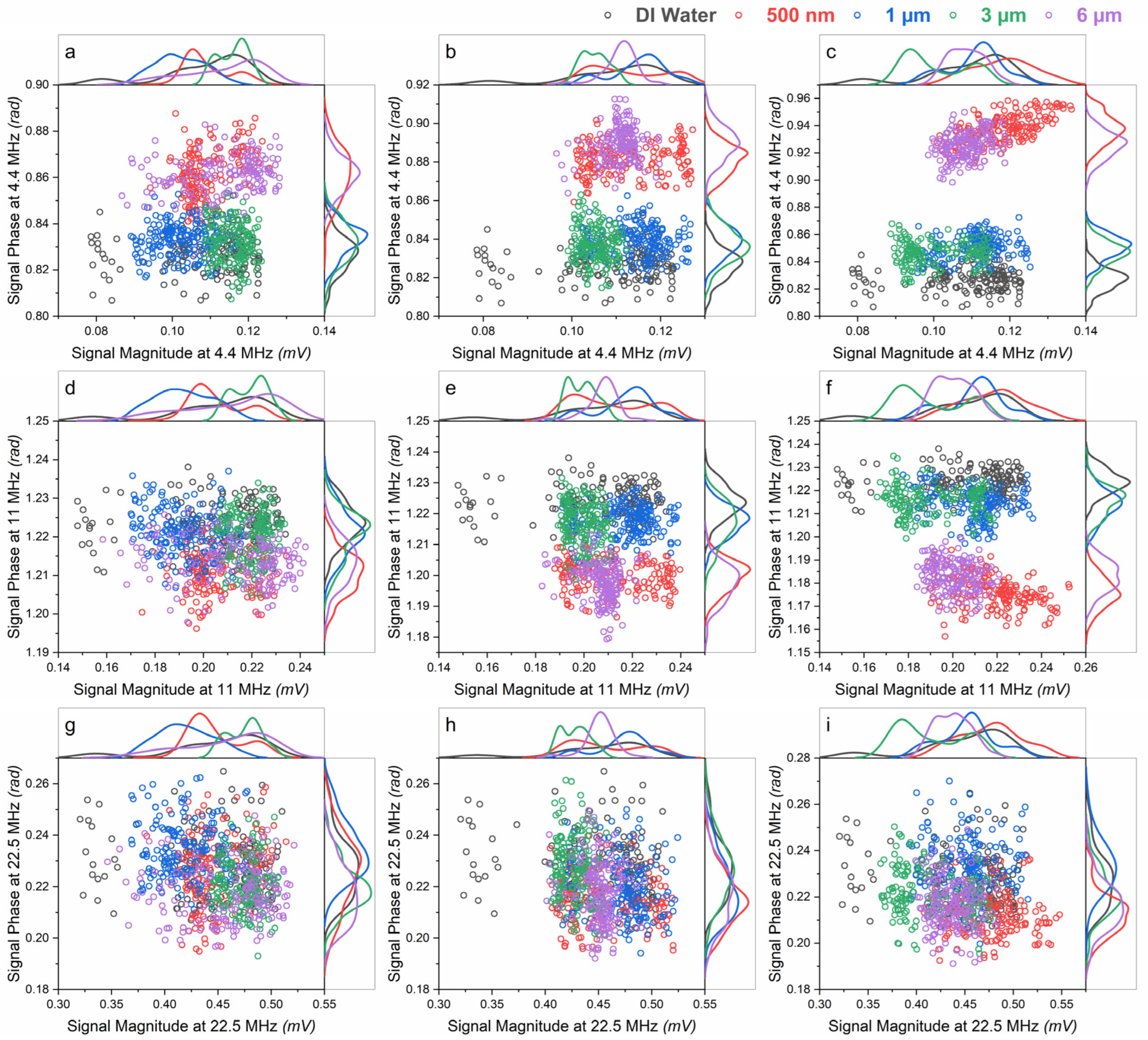
Each droplet produces two peaks of equal size and opposing signs in the signal detected by the lock-in amplifier. Only the peaks with positive values were recorded after the data were analyzed. The effect of the presence of microplastics in water on the signal magnitude and signal phase at different frequencies was visually evaluated to assess the feasibility of the proposed device for the detection of microplastics in water droplets. Figure 3 depicts all the peaks collected at each frequency for all treatments. The box plots of all the data are then shown at each frequency to visually compare the data statistics for each size and concentration (Figure S3a–f).
Figure 3 depicts the distinction between droplets containing microplastics and pure DI water droplets based on the low and medium frequencies signal phase. There is no meaningful difference based on signal magnitude measurements at low and medium frequencies. Furthermore, no signal magnitude or phase shift was seen in the high-frequency experiment.
According to Figure 3, the observed phase at low and medium frequencies is the best for distinguishing a population from DI water droplets since they are typically distributed and follow a general pattern. The scatter plots of medium-frequency phase vs. low-frequency phase diagrams of all droplets at three distinct concentrations are shown in Figure 4. Although there were clear overlaps between different categories, the distinction between 500 nm and 6 µm microplastics and the rest of the samples is obvious. The data in Figure 4 will be used in the subsequent analysis.

3.2. Effect of Surface Functionalization on the Signal Phase

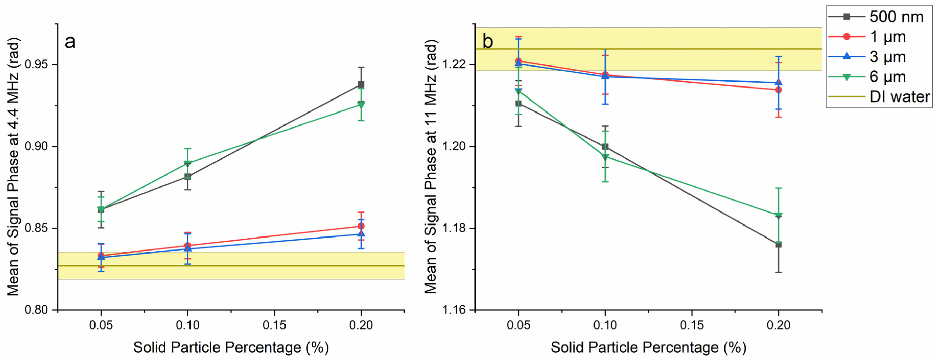
Figure 5 depicts the association between droplet microplastic concentration and mean signal phase at low and medium frequencies. The behavior of 500 nm and 6 µm microplastics is very similar, as is the behavior of 1 µm and 3 µm. The latter pair was discovered to be carboxyl-modified. Because the surface function factor was not originally one of the factors to be studied in this research, the experiment is not balanced enough to draw a statistical conclusion about the effect of this factor on the recorded signal. However, dielectrophoresis investigations have previously observed such a behavioral shift [38]. The carboxyl group of COOH-PS beads is ionized to COO in our suspending media, making the beads negatively charged. These charges will cause the formation of counterion double layers around suspended particles, and the polarization of these layers in response to an applied alternating current electric field will significantly influence the particles’ dielectric characteristics [39]. H+ ions in the suspending liquid will also boost its conductivity. This increase in medium conductivity will offset the loss in conductivity caused by the presence of microplastics as highly non-conductive substances. Furthermore, charged particles modify not only the polarization of droplets but also causes local net charges in the droplet, which changes the electric field [40,41]. As a result, negatively charged PS beads changed both the polarization of the droplets and the electric field itself, resulting in a decrease in the media’s dipole moment compared to the presence of inert polystyrene beads.

3.3. Effect of Size and Concentration on the Signal Phase

ANOVA was performed on the results as two distinct groups of inert and carboxyl-modified MPs. The ANOVA results indicated that concentration significantly affected all levels (p value 2 × 10⁻¹⁶). However, the size factor was insignificant at the medium frequency for carboxyl-modified PS beads (p value = 0.6688) and marginally insignificant at the low frequency for inert PS beads (p value = 0.0739). The post hoc Tukey HSD test demonstrates that distinguishing the size of microplastics in water droplets at low concentrations may be challenging. The difference in size levels becomes substantial when the concentration increases to 0.20%. This is only not true for medium frequency measurements of carboxyl-modified microplastic, where the influence of size is insignificant at all concentrations.
Microplastics in water increase the signal phase at low frequencies while decreasing it at medium frequencies, as seen in Figure 5. This is because the presence of microplastics causes a change in droplet conductivity. Cahill et al., numerically investigated the effect of droplet conductivity on signal phase. They demonstrated that at low frequencies, capacitive behavior dominates, resulting in a low phase angle. The medium resistance Rm dominates the impedance measurement at intermediate frequencies, and the phase angle reaches its maximum value. The phase angle will decrease at higher frequencies due to the system’s capacitive behavior. This behavior was found for various liquid conductivities, with a drop in conductivity causing this behavior to shift to lower frequencies [42]. This shift causes an increase in the signal phase with a decrease in conductivity at frequencies lower than Rm domination and a decrease in the signal phase with a decrease in conductivity at frequencies higher than Rm domination.

3.4. Device Sensitivity Estimation Using KNN

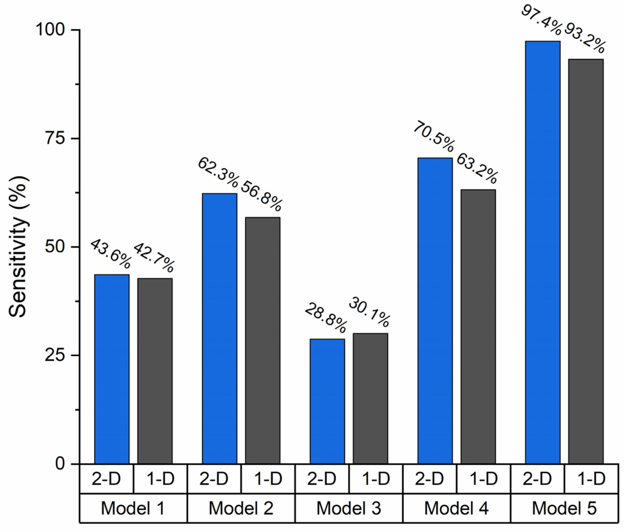
So far, an investigation into the droplet’s content has been conducted about the recorded phase response. However, the efficiency of the content classification technique must be considered when using droplet-based microfluidic impedance flow cytometry as a viable method for identifying microplastics in small samples. This motivates a study into a content-based categorization of the droplets. Five distinct 1-D and 2-D KNN models are trained to do this. Model 1 employs all three concentration categories and all four size categories. Model 2 includes three concentration levels with two groups: carboxyl-modified and inert microplastics. Model 3 solely employs carboxyl-modified microplastics at three concentrations and two size levels. Model 4 employs solely inert microplastics in three concentrations and two sizes. Model 5 employs inert microplastics at three concentration levels, with no size labels.
The droplet-based MIFC device, as shown in Figure 6, is not sensitive enough to detect carboxyl-modified microplastics. On the other hand, the device is susceptible to detecting inert microplastics at various concentrations. Although the statistical study demonstrated that the size of the microplastics can impact the recorded phase, the device is not sensitive enough to reliably distinguish the content of the droplets based on their size. Using two frequencies can improve sensor sensitivity compared to simply low frequency. However, measurement at multiple frequencies may be advantageous when distinguishing between biological particles and microplastics [17].

3.5. Equivalent Circuit

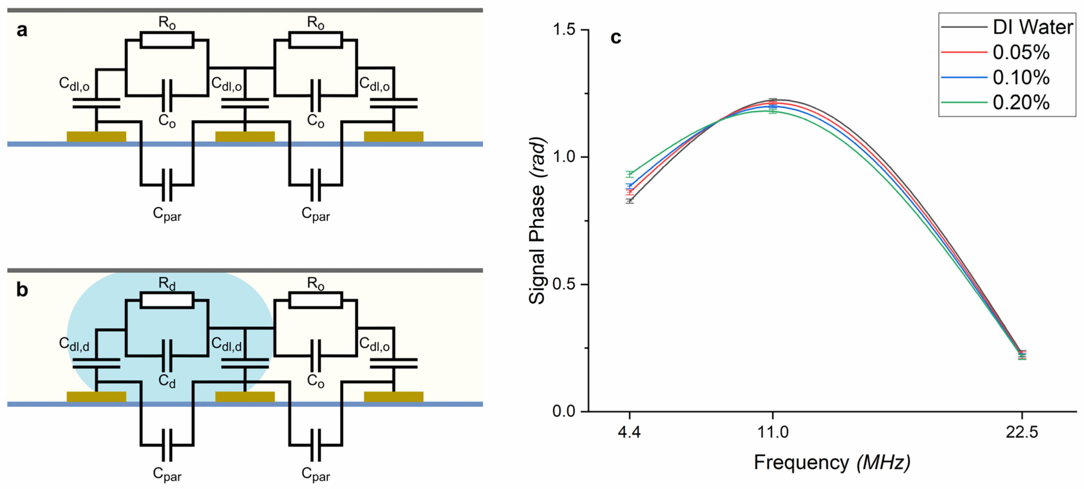
The equivalent electrical components are often combined in circuit models to simulate the impedance changes observed in impedance flow cytometry. By understanding the electrical behavior of microparticles through these equivalent components, researchers can extract valuable information about size, shape, and morphology. Figure 7 shows the equivalent circuit associated with the impedance sensor, which helps discuss the experimental results. Rd and Ro represent the resistance of droplets and oil, respectively, and changes by the microparticles as they move through the fluidic system and interact with the electric field. This resistance can vary depending on the particles’ size, shape, and conductivity. Cdl,d and Cdl,o represent the double-layer capacitors of the droplets and oil, which change due to the microparticles’ ability to store charge. The circuit always contains three double-layer capacitors. Double layers form at the oil–electrode interface when there is no droplet in the channel (Figure 7a). Two double layers are replaced by double layers at the water–electrode interface as soon as a droplet passes over the electrodes (Figure 7b). The droplet-covered electrode pair measures the impedance of droplet media, while the other electrode measures the impedance of mineral oil media. The parasitic capacitance is also present in all measurements induced by the electric field between wires, PCB connections, and the gold pattern on the glass. When a droplet contains microplastics, Rd and Cd vary, resulting in a phase and magnitude that differs from pure water droplet [43]. The values of Rd and Cd in our equivalent circuit model represent the aggregate effect of the micro beads within the droplet. Rd can be understood as the collective resistance of the micro beads and the surrounding medium, while Cd captures the combined capacitance of the microbeads and the droplet environment. This adds potential limitations and assumptions associated with using a simplified equivalent circuit model for such complex systems.
In a general sense, the capacitance of the double layer is the dominant characteristic at very low frequencies. The medium resistance Rd pre-dominates the impedance measurement at intermediate frequencies, and the phase rises to its highest possible value. When the frequency is increased, the medium capacitance, Cd, and the parasitic capacitance, Cpar, significantly influence the measured value [42].
The behavior of inert PS beads in droplets is depicted in Figure 7c. According to the proposed circuit, because the difference in the peaks is not significant, the microplastics in the droplet do not modify the resistive behavior of the media sufficiently to differentiate it. As the frequency increases, the disparity between the polylines grows, and eventually, they all converge. This indicates that the capacitive behavior of the droplet can be used to detect the presence of microplastics, as long as the frequency is not too high to allow the parasitic capacitance to dominate. The most significant difference between the signal phases is read at the lowest recorded frequency. This implies that microplastics will significantly affect the media’s double-layer capacitance. This could be because the polarity of the water molecules causes most of the polarization in this system. At higher frequencies, the larger water molecules may be unable to follow the pattern of the AC field. As a result, the microplastics can only disrupt the overall polarization at low frequencies.
This study marks the utilization of impedance measurement for microplastic detection, following Colson et al., study, which pioneered using microfluidic devices exclusively for microplastics [17]. In their research, impedance spectroscopy in a continuous flow system was demonstrated to detect polyethylene beads of various sizes from similarly sized biological materials in tap water. At 1.1 MHz, they showed that complex impedance change direction was generally the opposite for biological and plastic detections. The recovery rate for microplastics across different size ranges exceeded 90%, with a minimal false positive rate (1%) for misidentifying biological material as plastic. Also, they revealed a linear relationship between the microplastic sample diameter and the cube root of the real impedance change at 10 kHz.
Our developed droplet-based microfluidic impedance cytometer can distinguish microplastics’ concentration and surface functionalization in water droplets based on the measured signal phase observed at different frequencies. Size-specific microplastic detection depends on the frequency and surface properties of the microplastics. The addition of inert microplastics to water droplets resulted in decreased conductivity, causing the signal phase to increase at 4.4 MHz and decrease at 11 MHz. These findings emphasize that droplet-based microfluidic impedance flow cytometry is a promising technique for rapidly and accurately identifying and quantifying microplastics in water. This information is vital for in situ environmental monitoring and water quality assessment.

4. Conclusions

This study employed a novel droplet-based microfluidic impedance cytometer to detect microplastics in water. The investigation revealed the significant influence of microplastic concentration and surface functionalization on the measured signal phase at different frequencies. The conductivity and signal phase were significantly impacted based on the inert and carboxyl-modified microplastics, attributed to the breakdown of carboxyl groups on microplastic surfaces. In addition, size-specific microplastic detection depends on both the applied frequency and the surface properties of the microplastics. A k-NN model achieved a remarkable 97.4% sensitivity in categorizing droplets based on inert microplastic concentration. An equivalent circuit model was proposed, highlighting the dominance of double-layer capacitance at low frequencies and the impact of parasitic capacitance at high frequencies. The impedance flow cytometry-based detection technology allows real-time and fast-track testing through the electrical features of the particles. It facilitates analysis without time-consuming sample preparations and offline analysis.
Moreover, the microfluidic-based impedance enhances their capability of grouping and analyzing samples in parallel streams or droplets. Miniaturized impedance measurement devices, especially microfluidic-based ones, can significantly reduce the production cost of test equipment, making the technology more valuable and useful for spot-checks and field studies, improving testing efficiency. A reduced size would improve access to impedance flow cytometry-based techniques and expedite water sanitizing and management on-site where issues emerge. One of the limitations of the proposed method is the inability to differentiate microplastics from similar industrial-sized solid particles, which also have size and electrical features that are close proxies to those of microplastics. Similarly, it will not be possible to identify plastic of different types, shapes, and sizes that are generally mixed, which is an essential consideration in all microplastic analysis. There is room for further research to overcome these limitations and reach more detailed and specific identification. To enhance the comprehensiveness of our findings, future research should consider employing a broader range of microplastic sizes and utilizing realistic water samples.

Supplementary Materials

The following supporting information can be downloaded at: https://www.mdpi.com/article/10.3390/environments11050096/s1, Figure S1: The photomask that was used for electrode fabrication; Figure S2: The corresponding signal measured for frequency of 4.4 MHz; Figure S3: The box and whisker plot of the measurements at 4.4 MHz, (a) The signal magnitude, (b) The signal Phase, The box and whisker plot of the measurements at 11 MHz, (c) The signal magnitude, (d) The signal Phase, The box and whisker plot of the measurements at 22.5 MHz, (e) The signal magnitude, (f) The signal phase; Table S1: The full factorial design of the experiment.

Author Contributions

M.A.: Data curation, methodology, formal analysis, investigation, writing—original draft preparation, visualization. S.F.: Methodology, validation, writing—reviewing and editing. N.T.: Resources, project administration, writing—reviewing and editing. M.H.: Conceptualization, supervision, funding acquisition. All authors have read and agreed to the published version of the manuscript.

Funding

This research was funded by the Discovery Grant (RGPIN-2018-05726) from the Natural Sciences and Engineering Research Council (NSERC) of Canada.

Data Availability Statement

Dataset available on request from the authors.

Acknowledgments

We would like to acknowledge CMC Microsystems and Canada’s National Design Network (CNDN) for the provision of products and services that facilitated this research, including CAD tools, lock-in amplifier (HF2LI), and the transimpedance amplifier (HF2TA).

Conflicts of Interest

The authors declare no competing interests.

References

  1. Li, C.; Busquets, R.; Campos, L.C. Assessment of microplastics in freshwater systems: A review. Sci. Total Environ. 2020, 707, 135578. [Google Scholar] [CrossRef]
  2. Luo, H.; Liu, C.; He, D.; Xu, J.; Sun, J.; Li, J.; Pan, X. Environmental behaviors of microplastics in aquatic systems: A systematic review on degradation, adsorption, toxicity and biofilm under aging conditions. J. Hazard. Mater. 2022, 423, 12691. [Google Scholar] [CrossRef]
  3. Wang, C.; Zhao, J.; Xing, B. Environmental source, fate, and toxicity of microplastics. J. Hazard. Mater. 2021, 407, 124357. [Google Scholar] [CrossRef] [PubMed]
  4. Wang, L.; Wu, W.M.; Bolan, N.S.; Tsang, D.C.W.; Li, Y.; Qin, M.; Hou, D. Environmental fate, toxicity and risk management strategies of nanoplastics in the environment: Current status and future perspectives. J. Hazard. Mater. 2021, 401, 123415. [Google Scholar] [CrossRef]
  5. Xiang, Y.; Jiang, L.; Zhou, Y.; Luo, Z.; Zhi, D.; Yang, J.; Lam, S.S. Microplastics and environmental pollutants: Key interaction and toxicology in aquatic and soil environments. J. Hazard. Mater. 2022, 422, 126843. [Google Scholar] [CrossRef] [PubMed]
  6. Yang, L.; Zhang, Y.; Kang, S.; Wang, Z.; Wu, C. Microplastics in freshwater sediment: A review on methods, occurrence, and sources. Sci. Total Environ. 2021, 754, 141948. [Google Scholar] [CrossRef] [PubMed]
  7. Tan, H.; Mong, G.R.; Wong, S.L.; Wong, K.Y.; Sheng, D.D.C.V.; Nyakuma, B.B.; Othman, M.H.D.; Kek, H.Y.; Razis, A.F.A.; Wahab, N.H.A.; et al. Airborne microplastic/nanoplastic research: A comprehensive Web of Science (WoS) data-driven bibliometric analysis. Environ. Sci. Pollut. Res. 2023, 31, 109–126. [Google Scholar] [CrossRef] [PubMed]
  8. Shim, W.J.; Hong, S.H.; Eo, S.E. Identification methods in microplastic analysis: A review. Anal. Methods 2017, 9, 1384–1391. [Google Scholar] [CrossRef]
  9. Fu, W.; Min, J.; Jiang, W.; Li, Y.; Zhang, W. Separation, characterization and identification of microplastics and nanoplastics in the environment. Sci. Total Environ. 2020, 721, 137561. [Google Scholar] [CrossRef] [PubMed]
  10. Cowger, W.; Gray, A.; Christiansen, S.H.; DeFrond, H.; Deshpande, A.D.; Hemabessiere, L.; Primpke, S. Critical Review of Processing and Classification Techniques for Images and Spectra in Microplastic Research. Appl. Spectrosc. 2020, 74, 989–1010. [Google Scholar] [CrossRef]
  11. Primpke, S. Critical Assessment of Analytical Methods for the Harmonized and Cost-Efficient Analysis of Microplastics. Appl. Spectrosc. 2020, 74, 1012–1047. [Google Scholar] [CrossRef] [PubMed]
  12. Wiggin, K.J.; Holland, E.B. Validation and application of cost and time effective methods for the detection of 3–500 μm sized microplastics in the urban marine and estuarine environments surrounding Long Beach, California. Mar. Pollut. Bull. 2019, 143, 152–162. [Google Scholar] [CrossRef] [PubMed]
  13. Blevins, M.G.; Allen, H.L.; Colson, B.C.; Cook, A.M.; Greenbaum, A.Z.; Hemami, S.S.; Michel, A.P. Field-Portable Microplastic Sensing in Aqueous Environments: A Perspective on Emerging Techniques. Sensors 2021, 21, 3532. [Google Scholar] [CrossRef] [PubMed]
  14. Kniggendorf, A.-K.; Wetzel, C.; Roth, B. Microplastics Detection in Streaming Tap Water with Raman Spectroscopy. Sensors 2019, 19, 1839. [Google Scholar] [CrossRef] [PubMed]
  15. Takahashi, T.; Liu, Z.; Thevar, T.; Burns, N.; Mahajan, S.; Lindsay, D.; Watson, J.; Thornton, B. Identification of Microplastics in a Large Water Volume by Integrated Holography and Raman Spectroscopy. Appl. Opt. 2020, 59, 5073–5078. [Google Scholar] [CrossRef] [PubMed]
  16. Zhang, C.; Huang, K.-C.; Rajwa, B.; Li, J.; Yang, S.; Lin, H.; Liao, C.-S.; Eakins, G.; Kuang, S.; Patsekin, V. Stimulated Raman Scattering Flow Cytometry for Label-Free Single-Particle Analysis. Optica 2017, 4, 103–109. [Google Scholar] [CrossRef]
  17. Colson, B.C.; Michel, A.P.M. Flow-Through Quantification of Microplastics Using Impedance Spectroscopy. ACS Sens. 2021, 6, 238–244. [Google Scholar] [CrossRef] [PubMed]
  18. Hengstmann, E.; Fischer, E.K. Nile red staining in microplastic analysis—Proposal for a reliable and fast identification approach for large microplastics. Environ. Monit. Assess. 2019, 191, 612. [Google Scholar] [CrossRef]
  19. Huang, H.; Sun, Z.; Liu, S.; Di, Y.; Xu, J.; Liu, C.; Xu, R.; Song, H.; Zhan, S.; Wu, J. Underwater hyperspectral imaging for in situ underwater microplastic detection. Sci. Total Environ. 2021, 776, 145960. [Google Scholar] [CrossRef]
  20. Lv, L.; He, L.; Jiang, S.; Chen, J.; Zhou, C.; Qu, J.; Lu, Y.; Hong, P.; Sun, S.; Li, C. In situ surface-enhanced Raman spectroscopy for detecting microplastics and nanoplastics in aquatic environments. Sci. Total Environ. 2020, 728, 138449. [Google Scholar] [CrossRef]
  21. Zhang, X.; Zhang, H.; Yu, K.; Li, N.; Liu, Y.; Liu, X.; Zhang, H.; Yang, B.; Wu, W.; Gao, J.; et al. Rapid Monitoring Approach for Microplastics Using Portable Pyrolysis-Mass Spectrometry. Anal. Chem. 2020, 92, 4656–4662. [Google Scholar] [CrossRef] [PubMed]
  22. Morgan, H.; Sun, T.; Holmes, D.; Gawad, S.; Green, N.G. Single cell dielectric spectroscopy. J. Phys. D Appl. Phys. 2007, 40, 61–70. [Google Scholar] [CrossRef]
  23. Cheung, K.; Gawad, S.; Renaud, P. Impedance spectroscopy flow cytometry: On-chip label-free cell differentiation. Cytom. Part A 2005, 65A, 124–132. [Google Scholar] [CrossRef] [PubMed]
  24. Cheng, X.; Liu, Y.S.; Irimia, D.; Demirci, U.; Yang, L.; Zamir, L.; Rodríguez, W.R.; Toner, M.; Bashir, R. Cell detection and counting through cell lysate impedance spectroscopy in microfluidic devices. Lab Chip 2007, 7, 746–755. [Google Scholar] [CrossRef] [PubMed]
  25. Gawad, S.; Schild, L.; Renaud, P. Micromachined impedance spectroscopy flow cytometer for cell analysis and particle sizing. Lab Chip 2001, 1, 76–82. [Google Scholar] [CrossRef] [PubMed]
  26. Spencer, D.; Hollis, V.; Morgan, H. Microfluidic impedance cytometry of tumour cells in blood. Biomicrofluidics 2014, 8, 064124. [Google Scholar] [CrossRef] [PubMed]
  27. Bernabini, C.; Holmes, D.; Morgan, H. Micro-impedance cytometry for detection and analysis of micron-sized particles and bacteria. Lab Chip 2011, 11, 407–412. [Google Scholar] [CrossRef] [PubMed]
  28. Clausen, C.H.; Dimaki, M.; Bertelsen, C.V.; Skands, G.E.; Rodriguez-Trujillo, R.; Thomsen, J.D.; Svendsen, W.E. Bacteria Detection and Differentiation Using Impedance Flow Cytometry. Sensors 2018, 18, 3496. [Google Scholar] [CrossRef] [PubMed]
  29. Bertelsen, C.V.; Franco, J.C.; Skands, G.E.; Dimaki, M.; Svendsen, W.E. Investigating the Use of Impedance Flow Cytometry for Classifying the Viability State of E. coli. Sensors 2020, 20, 6339. [Google Scholar] [CrossRef]
  30. Chen, J.; Xue, C.; Zhao, Y.; Chen, D.; Wu, M.H.; Wang, J. Microfluidic impedance flow cytometry enabling high-throughput single-cell electrical property characterization. Int. J. Mol. Sci. 2015, 16, 9804–9830. [Google Scholar] [CrossRef]
  31. Cheung, K.C.; Berardino M di Schade-Kampmann, G.; Hebeisen, M.; Pierzchalski, A.; Bocsi, J.; Mittag, A.; Tárnok, A. Microfluidic impedance-based flow cytometry. Cytom. Part A 2010, 77A, 648–666. [Google Scholar] [CrossRef] [PubMed]
  32. Honrado, C.; Bisegna, P.; Swami, N.S.; Caselli, F. Single-cell microfluidic impedance cytometry: From raw signals to cell phenotypes using data analytics. Lab Chip 2021, 21, 22–54. [Google Scholar] [CrossRef] [PubMed]
  33. Spencer, D.; Caselli, F.; Bisegna, P.; Morgan, H. High accuracy particle analysis using sheathless microfluidic impedance cytometry. Lab Chip 2016, 16, 2467–2473. [Google Scholar] [CrossRef]
  34. Spencer, D.; Morgan, H. High-Speed Single-Cell Dielectric Spectroscopy. ACS Sens. 2020, 5, 423–430. [Google Scholar] [CrossRef]
  35. Song, H.; Wang, Y.; Rosano, J.M.; Prabhakarpandian, B.; Garson, C.; Pant, K.; Lai, E. A microfluidic impedance flow cytometer for identification of differentiation state of stem cells. Lab Chip 2013, 13, 2300–2310. [Google Scholar] [CrossRef]
  36. Spencer, D.C.; Paton, T.F.; Mulroney, K.T.; Inglis, T.J.J.; Sutton, J.M.; Morgan, H. A fast impedance-based antimicrobial susceptibility test. Nat. Commun. 2020, 11, 5328. [Google Scholar] [CrossRef] [PubMed]
  37. Sattari, A.; Hanafizadeh, P.; Hoorfar, M. Multiphase flow in microfluidics: From droplets and bubbles to the encapsulated structures. Adv. Colloid Interface Sci. 2020, 282, 102208. [Google Scholar] [CrossRef] [PubMed]
  38. Chen, Q.; Yuan, Y.J. A review of polystyrene bead manipulation by dielectrophoresis. RSC Adv. 2019, 9, 4963–4981. [Google Scholar] [CrossRef]
  39. Wang, X.B.; Vykoukal, J.; Becker, F.F.; Gascoyne, P.R.C. Separation of Polystyrene Microbeads Using Dielectrophoretic/Gravitational Field-Flow-Fractionation. Biophys. J. 1998, 74, 2689–2701. [Google Scholar] [CrossRef]
  40. Makino, K.; Yamamoto, N.; Higuchi, K.; Harada, N.; Ohshima, H.; Terada, H. Phagocytic uptake of polystyrene microspheres by alveolar macrophages: Effects of the size and surface properties of the microspheres. Colloids Surf. B Biointerfaces 2003, 27, 33–39. [Google Scholar] [CrossRef]
  41. Yan, Y.; Luo, J.; Guo, D.; Wen, S. Dynamic Dielectrophoresis Model of Multi-Phase Ionic Fluids. PLoS ONE 2015, 10, e0117456. [Google Scholar] [CrossRef]
  42. Cahill, B.P. Optimization of an impedance sensor for droplet-based microfluidic systems. In Smart Sensors, Actuators, and MEMS V; SPIE: Bellingham, WA, USA, 2011; Volume 8066, pp. 133–140. [Google Scholar] [CrossRef]
  43. Kemna, E.W.M.; Segerink, L.I.; Wolbers, F.; Vermes, I.; van den Berg, A. Label-free, high-throughput, electrical detection of cells in droplets. Analyst 2013, 138, 4585–4592. [Google Scholar] [CrossRef]
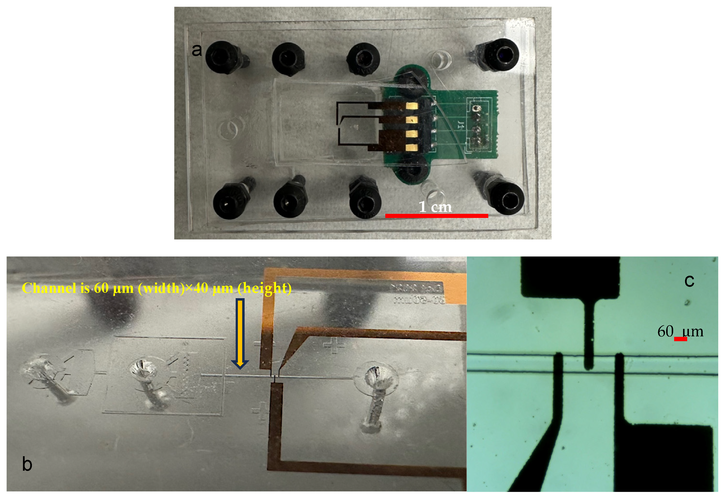
Figure 1. (a) The final device, (b) the dimension of the channel, and (c) the coplanar electrodes at the bottom of the microchannel.
Environments 11 00096 g001
Figure 2. (a) The actual microfluidic chip, and (b) the measurement setup including syringe pump (left), the optical microscope (middle), and the lock in amplifier (right). The arrows show the magnified image of actual device under the optical microscope.
Environments 11 00096 g002
Figure 3. Signal phase vs. signal magnitude for all the measurements for all droplet contents at (a) 0.05% solid particle concentration at 4.4 MHz, (b) 0.10% solid particle concentration at 4.4 MHz, (c) 0.20% solid particle concentration at 4.4 MHz, (d) 0.05% solid particle concentration at 11 MHz, (e) 0.10% solid particle concentration at 11 MHz, (f) 0.20% solid particle concentration at 11 MHz, (g) 0.05% solid particle concentration at 22.5 MHz, (h) 0.10% solid particle concentration at 22.5 MHz, (i) 0.20% solid particle concentration at 22.5 MHz.
Environments 11 00096 g003
Figure 4. Signal phase at 11 MHz vs. signal phase at 4.4 MHz for all the droplet contents for (a) 0.05% solid particle content, (b) 0.10% solid particle content, (c) 0.20% solid particle content.
Environments 11 00096 g004
Figure 5. Effect of solid particle concentration of the mean of the signal phase at (a) 4.4 MHz, (b) 11 MHz.
Environments 11 00096 g005
Figure 6. The estimated sensitivity of the device using hold-out validation for different models. The device shows poor performance in the classification of carboxyl-modified MPs, while it can successfully classify the inert ones.
Environments 11 00096 g006
Figure 7. An equivalent circuit is associated with the impedance sensor in (a) an empty channel and (b) a channel with a droplet. (c) The signal phase vs. frequency of inert microplastic at different concentration levels. Rd and Ro: Represent the resistance of droplets and oil, respectively. Cdl,d and Cdl,o: Represent the double-layer capacitors of the droplet and oil, respectively, which change due to the microbeads’ ability to store charge. Cpar: Represent the parasitic capacitance, which is also present in all measurements induced by the electric field between wires, PCB connections, and the gold pattern on the glass.
Environments 11 00096 g007
Disclaimer/Publisher’s Note: The statements, opinions and data contained in all publications are solely those of the individual author(s) and contributor(s) and not of MDPI and/or the editor(s). MDPI and/or the editor(s) disclaim responsibility for any injury to people or property resulting from any ideas, methods, instructions or products referred to in the content.