Abstract
A systematic sensitivity analysis using three-dimensional discrete element models with discrete fracture networks (DEM-DFN) was conducted to evaluate underground excavation support in jointed rock masses at the CLAB2 site in Southeastern Sweden. The site features a joint network comprising six distinct joint sets, each with unique geometrical properties. The study examined 10 DFNs and 19 rock bolt patterns, both conventional and unconventional. It covered 200 scenarios, including 10 unsupported and 190 supported cases. Technical and economic criteria for stability were assessed for each support system. The results indicated that increasing rock bolt length enhances stability up to a certain point. However, multi-length rock bolt patterns with similar consumption can yield significantly different stability outcomes. Notably, the arrangement and properties of rock bolts are crucial for stability, particularly in blocks between bolting sections. These blocks remain interlocked in unsupported areas due to the induced pressure from supported sections. Although equal-length rock bolt patterns are commonly used, the analysis revealed that triple-length rock bolts (3, 6, and 9 m) provided the most effective support across all ten DFN scenarios.
1. Introduction
The challenges related to support system design and the stability of a tunnel wall and tunnel roof are vital for underground construction. Usually, jointed rock masses are encountered during underground excavation. There are severe consequences of failure that occur on tunnel walls and roof blocks. These include safety issues, delays in progress, and damage to surface structures. Such failures are particularly concerning when the space is excavated at shallow depths [1,2].
The distinct element method (DEM) is promptly becoming popular in analyzing the behavior of underground spaces constructed in jointed rock masses [3,4,5,6]. However, this method is rarely used as a design procedure and is primarily employed to demonstrate the performance of tunnel support systems. To design the support systems, conventional analytical or empirical methods were used where the jointed rock mass is considered as a continuum medium. Therefore, a rock mass’s geomechanical characteristics are defined based on classification systems, ignoring the behavior of individual joints (e.g., geological strength index (GSI) system, Q-system, the rock mass rating (RMR)) [7,8,9]. Thus, the advantage of using numerical approaches, such as the FEM and DEM, for the support design has been minimal [10]. The Finite Element Method (FEM) is a highly effective technique for studying tunnels that are supported by rock bolts. It’s been widely used in research, primarily to understand how loads are transferred within a continuous rock mass in these types of tunnels [11,12,13]. However, this method has limitations in blocky and jointed rock masses, especially when the detachment of blocks is required. Despite FEM, the DEM approach is mostly used for highly jointed rock masses, which is mostly used when the displacement of the blocks along joints are demanded.
In addition to the joint set defined in the DEM, the discrete fracture network (DFN) model can monitor discontinuities. This is conducted using site-specific investigations to produce geometries closer to the real geology. These discontinuities can then be stochastically simulated and used explicitly as a design input. In DFN simulations, the fracture system’s geometry is formed from a stochastic demonstration. This is achieved using probabilistic density functions of discontinuity parameters such as orientation, size, location, density, and aperture. This approach reduces the inherent uncertainty of discontinuity networks in jointed rock masses based on the Monte Carlo method [11,12,13,14,15].
The previous studies were often performed considering case studies with commonly used rock bolt patterns and rock bolt properties, as well as considering two constitutive model types for rock bolts, namely elastic and elastic–perfectly plastic, either in two or three stages, and implementing a regular and deterministic arrangement of the discontinuities [16,17,18,19,20,21,22,23,24,25,26,27,28,29]. Few studies have used the DEM-DFN approach to examine the optimal rock bolt pattern in a medium with discontinuous and stochastically arranged discontinuities. A detailed parametric analysis was conducted to assess how the length and spacing of bolts impact the design of support system patterns [30]. This analysis specifically looked at their effect on the tensile safety factor of bonded bolts [29,30,31]. Therefore, the two-dimensional plane strain concept of the DEM simulations was validated against the existing solution in an elastic medium. A wide-span opening was excavated in a horizontally stratified jointed rock mass using the distinct element method (DEM) to provide a better understanding of the rock bolt support mechanisms and forces [30]. The Opera House’s underground car park with a cavern roof in Sydney was selected as a case study simulation [25]. The calculated deflections of the cavern roof are in reasonable agreement with the field measurements. The results highlight the significance of the geological conditions encountered for the rock bolt support for wide-span underground excavations. A parametric study was conducted to examine the influence of bolt length and diameter on the induced displacements in a jointed rock mass using a finite-element approach [32,33]. Three types of jointed systems were considered: normal joint closure, the combination of normal and shear joint closure, and joints loaded in a shear condition. The displacements on the excavation boundary were investigated for each joint type. The results show that increasing the bolt length from 3 to 6 m can significantly increase the confidence level, but not as much from 6 to 9 m. Additionally, the rock bolt length does not necessarily and significantly reduce the wall displacement. However, increasing the bolt diameter considerably decreases the tunnel wall displacement. Typically, researchers assess how effective a support pattern is by using two-dimensional models that incorporate a regular system of discontinuities. In designing a support pattern for an irregular jointed rock mass, a single discontinuity fracture network realization is employed [33,34,35,36].
The main purpose of this research is to investigate the efficiency of optimal rock bolt patterns, including length distribution and spacing. It also examines the financial and technical viability of the stability of underground constructions in jointed rock masses. To achieve this, a systematic numerical investigation was conducted using the three-dimensional DEM-DFN. This approach highlights the role of DEM-DFN in the design of tunnels in fractured rock masses. Additionally, the main design parameters of rock bolts, such as length and spacing, were considered. We investigate ten DFN realizations and 19 different bolting (spacing and length) patterns.
2. Materials and Methods
The study area is the CLAB2 cavern, located near the Simpevarp area in Southeastern Sweden. The cavern measures 115 m in length, 21 m in width, 27 m in height, and 30 m in depth. The main purpose of constructing this cavern is to store nuclear waste and substances that are hazardous to human health and the environment.
The geological composition of the Clab2 cavern area is predominantly made up of granitic rocks and associated metavolcanic materials. Within this region, the cavern itself is specifically excavated in the metavolcanite zone. These metavolcanites are essentially transformed volcanic andesites that have undergone recrystallization as a result of granite intrusions in the vicinity. This process not only alters their original structure but also affects their mineralogical properties, creating a unique environment within the cavern. The interaction between the granites and the altered volcanic rocks plays a significant role in shaping the physical characteristics of the cavern, influencing the stability of the cavern due to its highly fractured environment.
A comprehensive joint study was conducted to evaluate the geological features. Suitable distribution functions of joint persistence, dip angle, orientation, and aperture are fitted to generate discrete fracture networks [37].
2.1. Discrete Fracture Network Modeling
Stochastic discrete fracture network (DFN) realizations are used to assess the stability of the rock mass underground. They provide a detailed and probabilistic representation of the fracture networks within rock masses. This representation is critical for understanding and predicting the behavior of these structures during excavation.
DFN models provide an explicit representation of fractures, capturing their geometric characteristics such as orientation, spacing, and intensity. These features are essential for assessing the stability of rock masses around tunnels. The models account for the inherent variability and uncertainty present in fracture networks, allowing for probabilistic stability analyses. This methodology aids in understanding the range of possible outcomes and the likelihood of various failure scenarios by simulating realistic geological conditions. By using measured data and probabilistic distributions, DFN models create more accurate representations of the rock mass surrounding tunnels. Additionally, these models evaluate the effectiveness of support systems in tunnels by simulating different scenarios. They analyze how fractures influence stability and the necessary support measures. Stochastic modeling in geomechanical design enhances the reliability and efficiency of engineering projects by effectively incorporating and managing uncertainties. This approach not only improves decision-making and reduces computational efforts but also provides a robust framework for risk assessment and parameter estimation across various complex applications.
Discrete fracture network (DFN) models are essential for rock mass stability analysis, particularly in complex geological settings where fractures significantly influence mechanical behavior. These models help in the understanding of the structural and mechanical characteristics of rock masses, which are crucial for assessing stability in various engineering applications, such as slope stability and underground excavations. These models are often coupled with numerical methods like the discrete element method (DEM) to assess the stability of rock slopes and underground excavations. For instance, a study demonstrated the use of DFN-DEM modeling to analyze the stability of a rock slope in the French Alps, highlighting the role of rock bridge failure in generating a new failure [35]. Similarly, DFN models have been applied in underground projects to capture the three-dimensional loading of tunnel supports. They also identify intersecting discontinuity planes. This enhances the understanding of rock mass movement during tunnel excavation [37].
DFN models offer several advantages over traditional continuum models by capturing the non-continuous characteristics of rock masses. They allow for the random generation of fracture networks using probabilistic distribution functions. Additionally, they provide a grid generation strategy for discrete-element methods, which is crucial for analyzing the stability of fractured rocks around excavations. DFN models can also be refined with various realizations to identify complex rock blocks and block groups. This refinement is critical for the stability analysis of underground excavations [38,39,40,41].
Moreover, a probabilistic analysis using stochastic DFN models is crucial for assessing the stability of fractured rock masses, especially in the presence of uncertainties in fracture geometrical properties. This approach allows for a more comprehensive evaluation of rock structure stability. It considers different combinations of joint set geometrical parameters. Additionally, it assesses their impact on the required support patterns [37,40]. Such analyses are vital for ensuring safety in engineering projects involving rock masses [42,43,44].
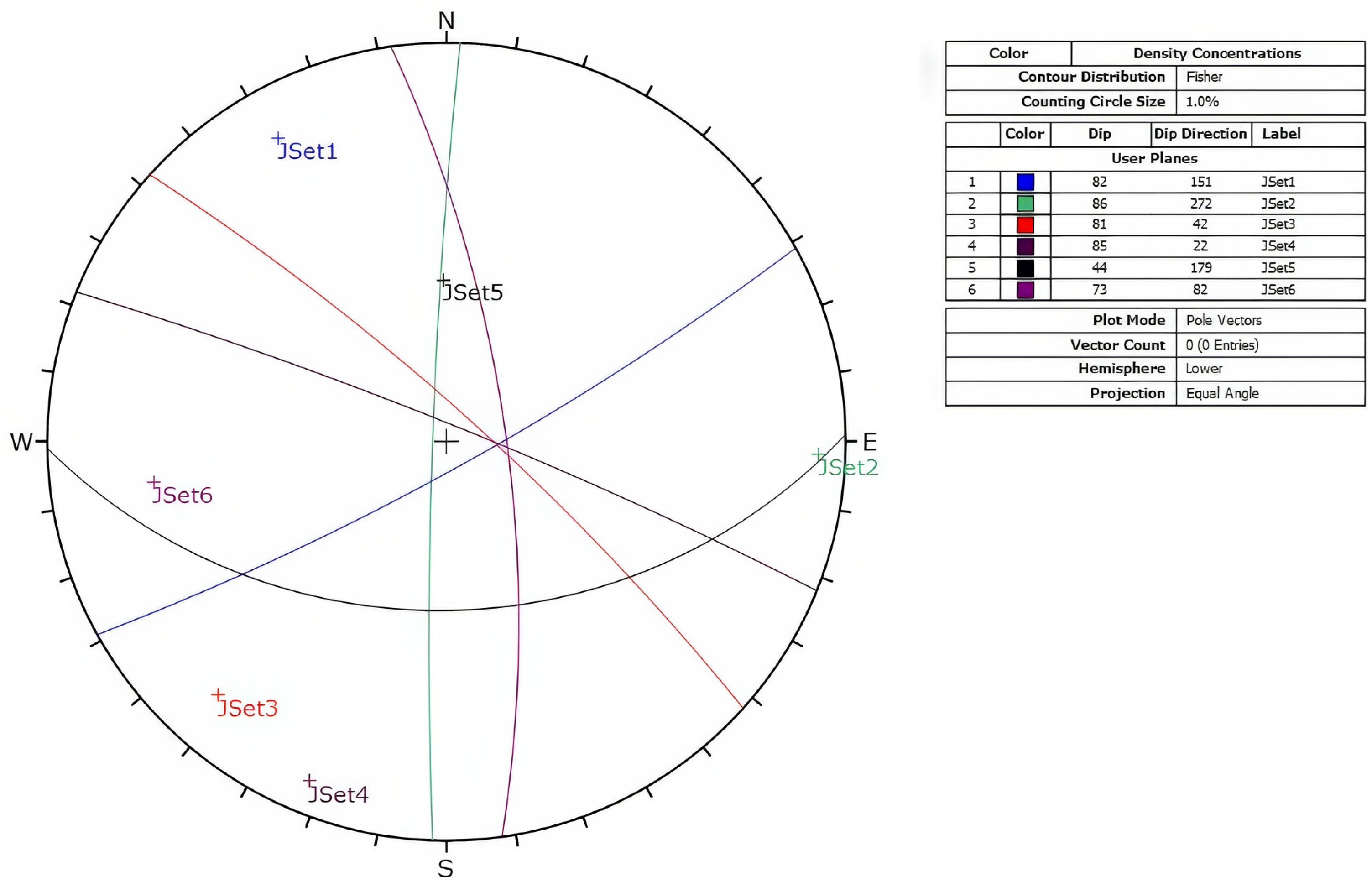
The geomechanical properties of the cavern rock mass were used as data sources to generate DFN realizations. In this research, conducting generic studies of stability analysis does not necessarily reflect the actual site conditions. Joint studies in the area were conducted using stereographic maps. Maps identified six joint sets around the cavern. Table 1 presents the geometric and statistical properties of the six joint sets of the region, along with the material properties of the intact rock and the discontinuities. The information in Table 1 includes the dip, dip direction, Fisher distribution coefficient, joint density, intensity of jointing, and distribution functions. Figure 1 illustrates the mean values of the dip and dip direction for the six joint sets on the stereonet. Table 2 consists of two sections for intact rock and the discontinuities. The information includes the joint roughness coefficient (JRC), joint compressive strength (JCS), residual friction angle, basic friction angle, stiffness normal (JKn), stiffness shear (JKs), dilation, critical shear displacement, initial aperture, residual aperture, and maximum aperture.

Table 1.
Geometrical and statistical characteristics of the six joint sets and geomechanical parameters of the intact rock and discontinuities [35,36].
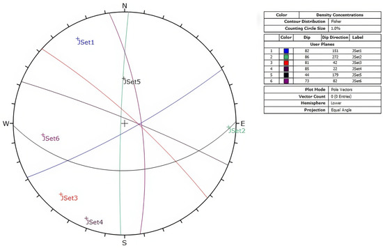
Figure 1.
The great circle and pole illustration of the orientation for the six joint sets.
Table 2.
Geomechanical parameters of the intact rock and discontinuities [35].
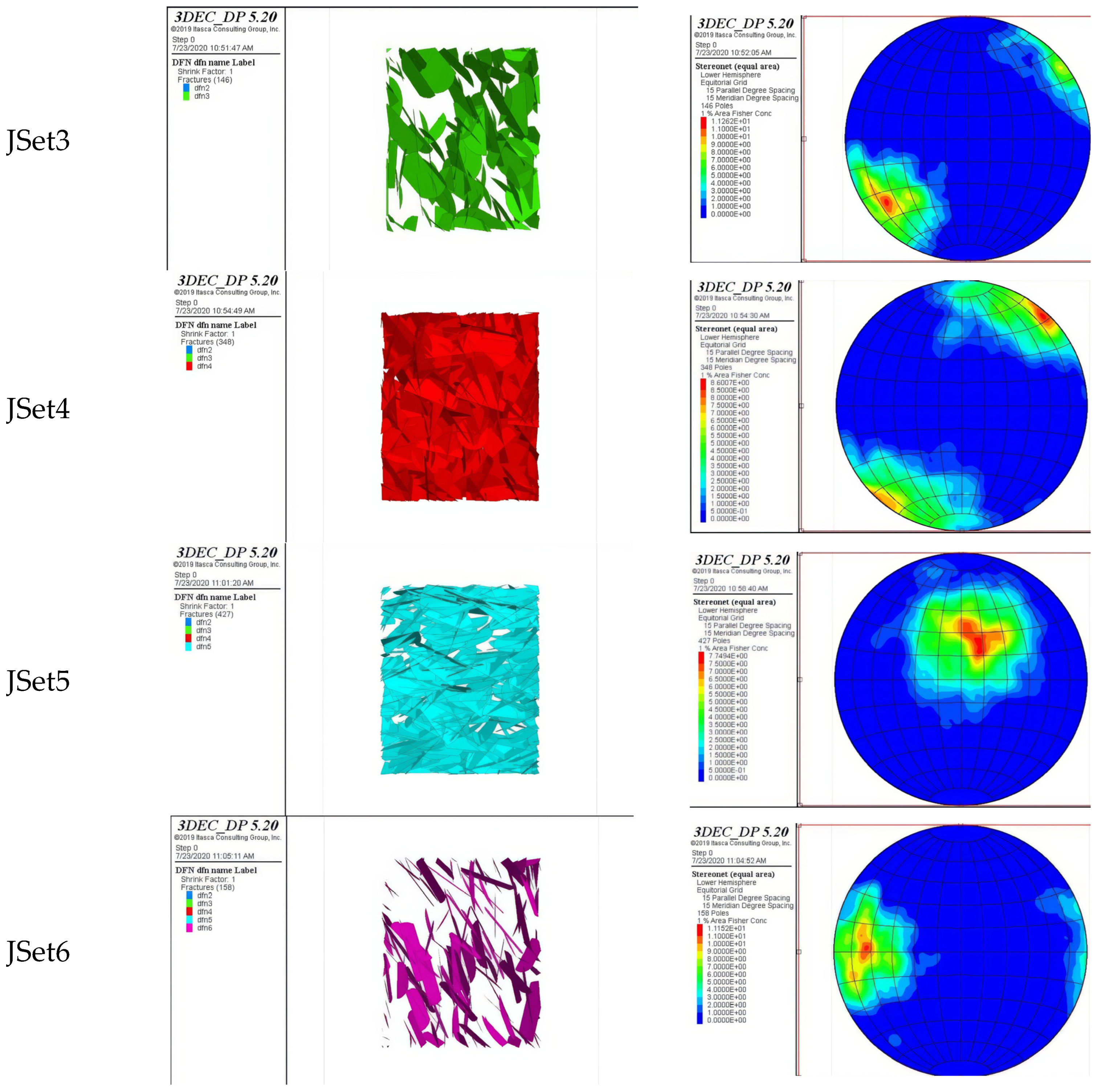
To ensure the agreement of the simulated rock mass with the actual surveyed discontinuities, each joint set is modeled individually, and the stereonet graph is extracted accordingly. Figure 2 presents the simulated joint sets along with the pole distribution of each on stereonet. The figure shows that the numerical simulation reflects the surveyed joint sets presented in Figure 1. Based on Figure 1 and Figure 2, there is a strong correlation between the results of the geometrical generation in the numerical simulation and the surveyed joint sets at the cavern site, as the pole concentrations are very similar. Afterward, ten sets of DFN realizations were generated based on the stochastic data presented in Table 1. Considering these realizations, the modeled DFNs resembles a realistic representation of the natural rock mass with scattered and spatially distributed discontinuities. However, DFN models follow characteristic patterns without compromising monitored geotechnical investigation data. These simulated rock mass models will be used to quantify block size distribution, considering explicitly modeled discontinuities.
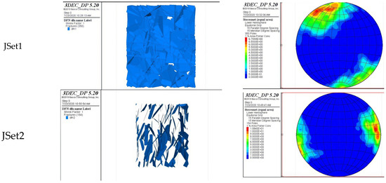

Figure 2.
The illustration of DFN generated for the six joint sets and the related stereonets from the numerical simulation.
2.2. Rock Bolt Ground Support Design
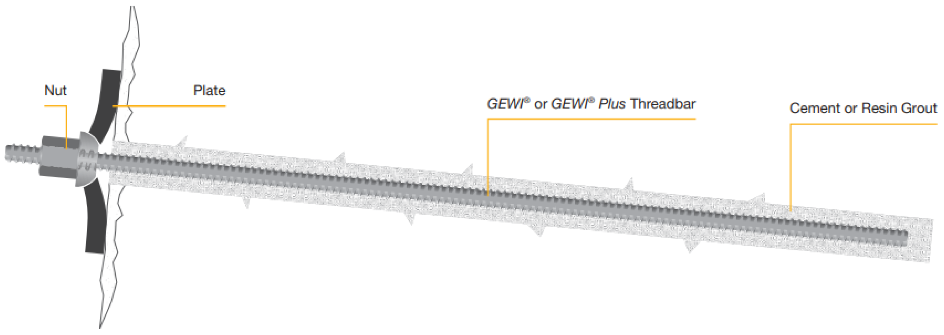
After generating the ten discrete fracture networks, the boundary conditions applied and the cavern excavated are studied. In this study, a typical fully grouted rock bolt from the well-known GEWI® brand, named GEWI Threadbar (Figure 3), along with shotcrete and steel mesh, is used for the support system. The detailed physical and mechanical properties of the rock bolts, shotcrete, and steel mesh are presented in Table 3. The table includes the nominal diameter, steel grade, ultimate strength, yield strength, cross-sectional area, second moment of inertia, reinforcement stiffness, weight, square anchor plate dimension for rock bolts, Poisson’s ratio, uniaxial compressive strength, shear modulus, and Young’s modulus for the injected grout and applied shotcrete.
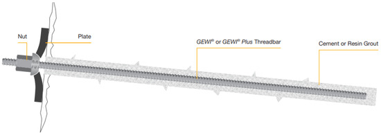
Figure 3.
An illustration of the GEWI Threadbar rock bolt.
Table 3.
Mechanical properties of the used GEWI Threadbar rock bolts and grout.
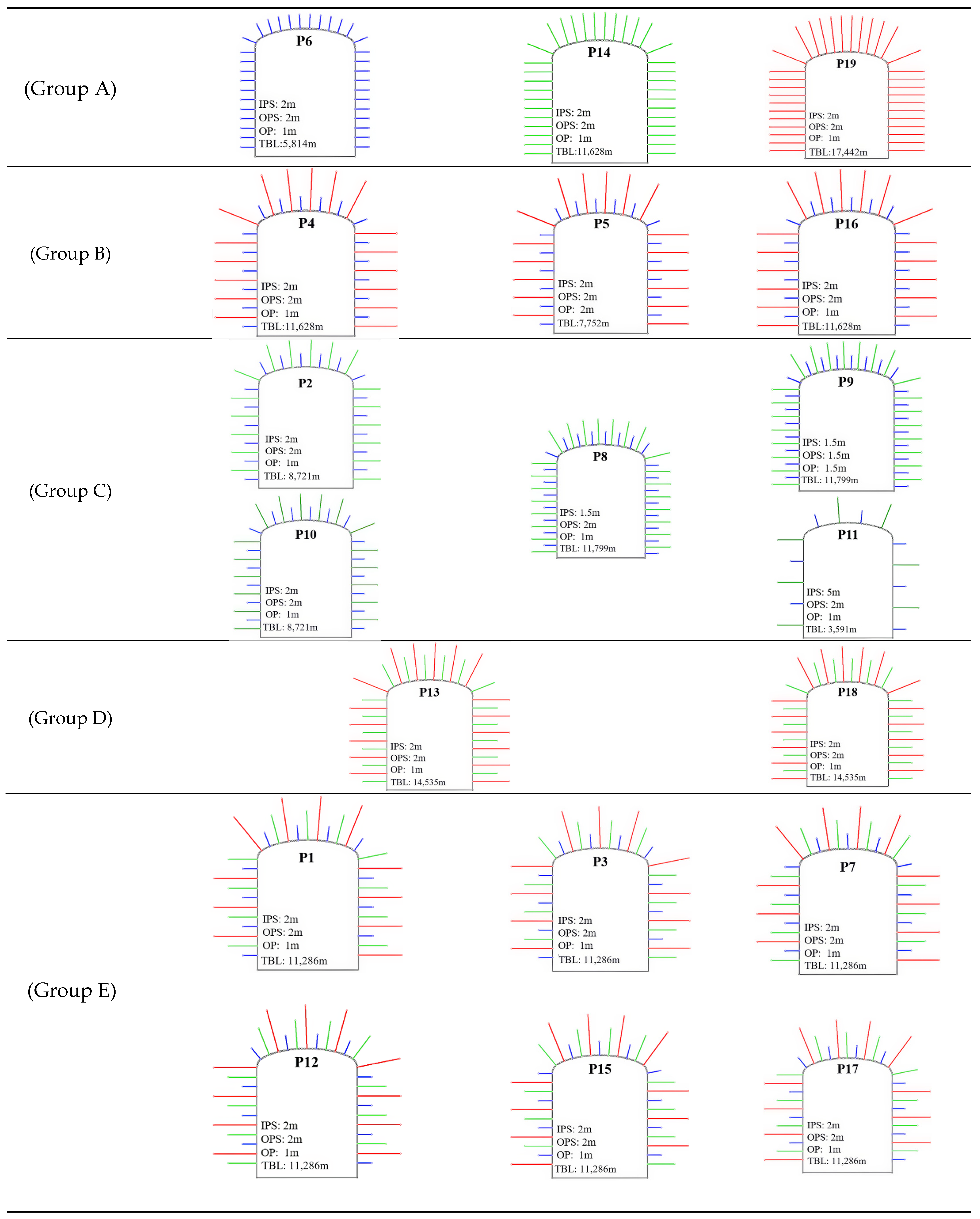
A systematic support system design implementing 3, 6, and 9 m rock bolts is applied to the tunnel wall with various commonly used longitudinal and transverse spacings of 1.5, 2, and 5 m with different bolt length distributions. Figure 4 illustrates the 19 rock bolting pattern geometries implemented for the analyses. These patterns are developed based on the Australian, South African, and Canadian bolting patterns commonly used in underground mines in these regions [39]. A novel procedure is introduced to evaluate the performance of the bolt support system pattern, accounting for both technical and financial aspects. Therefore, two technical criteria have been used, including the total volume of unstable blocks (VT) and the volume of which 90% of the unstable blocks are smaller (V90) than a specific volume, which is considered as 0.5 m3 in this research. To evaluate the stability of the generated DFN models, the DEM-based code (3DEC 5.2) was implemented after defining all ten DFN realizations and the considered rock bolt patterns. To have an overview of the stability analysis procedure, Figure 5 presents the flowchart of the performed numerical analyses, including the ten DFN realizations and 19 rock bolt patterns while considering the technical and economic criteria for selecting the optimal bolting pattern.
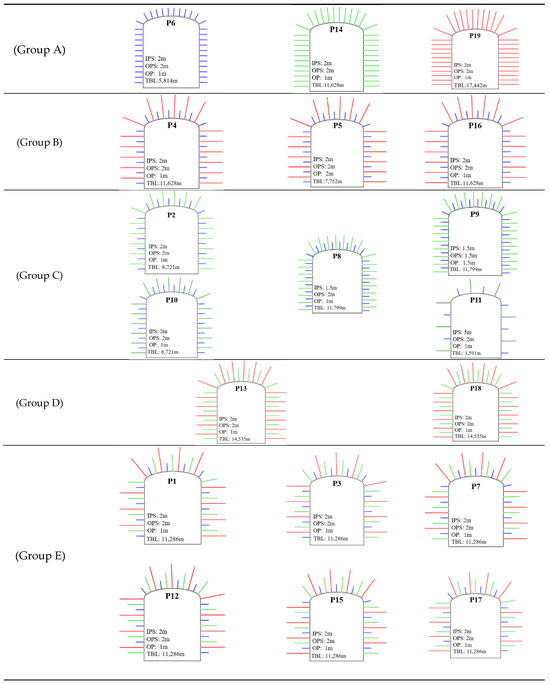
Figure 4.
The 19 rock bolt support pattern details considered in the study. (A) Single length pattern. (B) dual rock bolts length form out of 3 and 9 m. (C) dual rock bolts length form out of 3 and 6 m (D) dual rock bolts length form out of 6 and 9 m. (E) triple rock bolts length form out of 3, 6, and 9 m. IPS: in-plane spacing, OPS: out-of-plane spacing, OP: offset from portal, TBL: total bolt length.
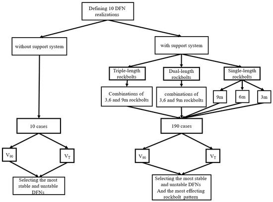
Figure 5.
The flowchart of the performed numerical analyses, including ten DFN realizations and 19 rock bolt patterns.
2.3. Numerical Modeling Results and Discussion
The stability of the cavern is examined before and after support installation to evaluate the effectiveness of the rock bolt patterns. In order to be able to compare the response of the DFN realization to the support patterns, each generated DFN realization is saved. Then, the 19 support patterns are applied to the identical DFN realization.
It should be noted that the intact rock within the rock mass is treated as rigid because of its very high elastic modulus (77 GPa) reported in Table 3. Consequently, the stability of the excavation is governed by the displacement of discontinuities rather than the deformation of the intact blocks, which results in unmeshed intact rock, which is in agreement with the actual condition. However, if the block deformation were significant, it would be necessary to model deformable blocks. In such cases, both internal block deformation and displacement along discontinuities would affect excavation stability.
To assess the stability of the tunnel supported by each pattern, a code is developed with the Python programming language to extract the unstable blocks based on their displacement trend. The obtained results for VT and V90 of the ten DFN realizations before and after rock bolt installation are shown in Table 4. In this table, the highlighted cells present the unstable models based on the proposed criterion, as the volume of the block is greater than 0.5 m3 (V > 0.5 m3). The results compared different host rocks with different DFNs, which resulted in a significant difference between the stability conditions of the ten DFNs.
Table 4.
The V90 and VT values for the analyses of DFN realizations and support patterns obtained from the Python code.
The significance of stochastic and probabilistic design in geomechanical structures with inherent uncertainties is highlighted by various DFN realizations, which illustrate the unstable block zones. Figure 6 illustrates the DFN generation of the most and least stable DFN realizations and their block displacements before applying the support, along with a sample of the support pattern (P17) with three rock bolt lengths. The effect of using a support system may vary across different DFN realizations. In other words, a DFN with relatively low stability may reach a higher stability after support installation compared to other DFN realizations (Table 4). This result was observed for DFN test 6, in which we calculated the highest instability among other cases before installing the support system. In contrast, while DFN tests 3 and 10 illustrate the highest tunnel instability, they also experience the lowest stability condition after the installation of the rock bolt support system. The most stable realizations before installation may not necessarily be among the best cases after installation. This is calculated for DFN realizations number 2 and number 5. This finding reveals that the behavior of the DFNs is not necessarily predictable before and after the support installation. This can confirm the necessity of implementing a series of DFN realizations in order to present results closer to real geology. This is due to the wide range of unstable block volumes that insist on examining various DFN realizations to define the most effective pattern.
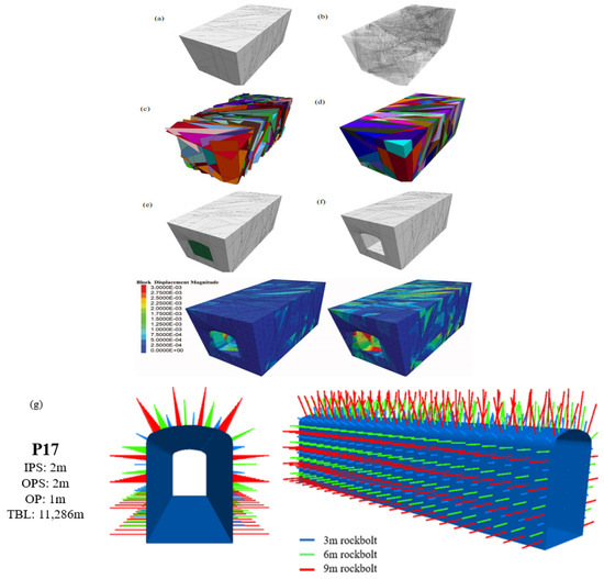
Figure 6.
The unstable block zones for the most stable (left) and unstable (right) DFN realization, The generated DFN regularized discrete rock mass; (a–f) present the steps of the excavating tunnel in DFN blocks along with the displacements induced in the fractured network before the support installation (g) presents a sample pattern (P17) generated with three rock bolt lengths.
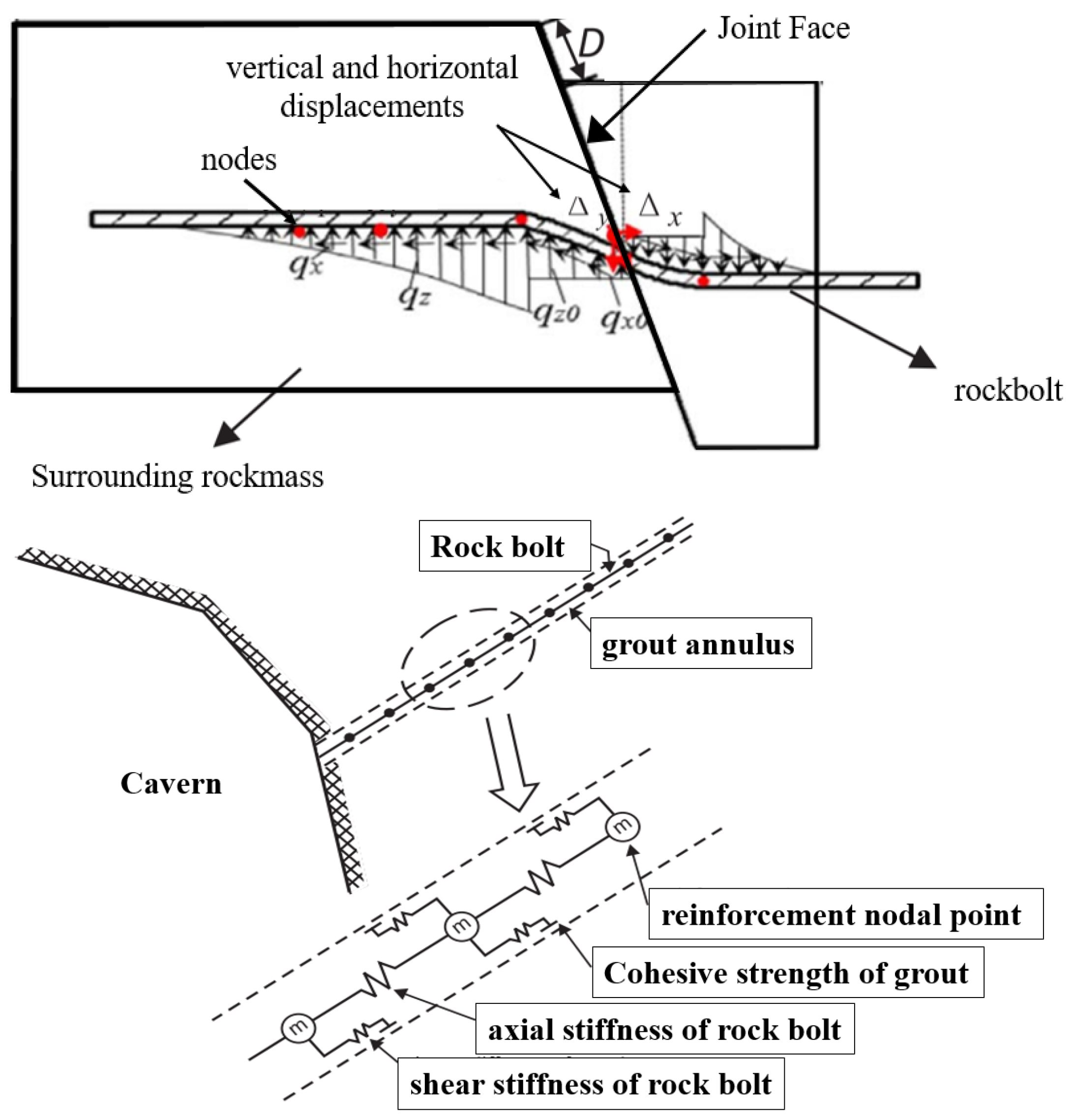
After implementing the rock bolt support patterns on the generated DFN realizations, the stress and load generation in the rock bolts due to the displacement of blocks were defined. The rock bolt’s constitutive model is considered elastic–perfectly plastic, leading to deformation in the sheared zone (hinge) which occurs on the intersection of the discontinuities. As the joint displacement increases, the shear and compressive stresses along the rock bolt rise significantly, with the maximum stress concentrations occurring at the joint face. The formation of plastic zones initiates at the joint face and extends along the bolt as the displacement increases. Increased joint displacement not only elevates stress levels but also reduces the interaction force between the rock and the bolt, indicating a potential underutilization of the bolt’s strength. Figure 7 shows the axial and shear force distribution induced in the rock bolt due to the joint face movement, where Δx and Δy are the horizontal and vertical displacements of the shear zone, respectively, and qx and qz are the axial and shear forces, respectively.
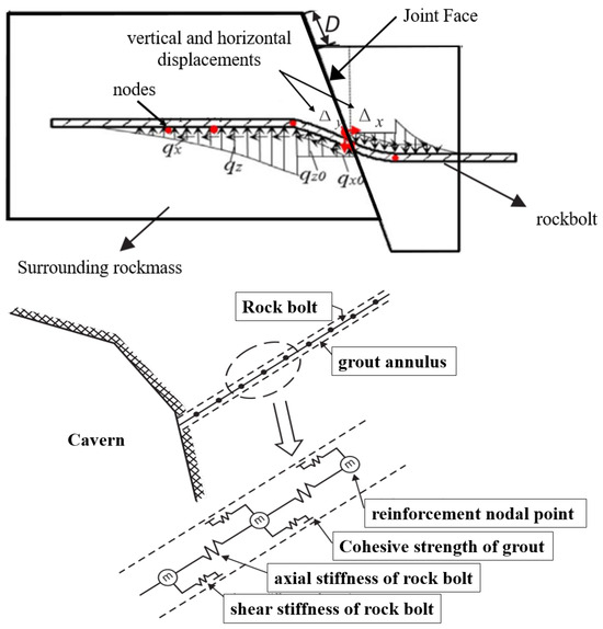
Figure 7.
The axial and shear force distribution induced in the rock bolt due to the joint face displacement (top). The conceptual mechanical representation of fully bonded reinforcement, which accounts for shear and cohesive behavior of the grout annulus (bottom).
The research utilized a rockbolt as the structural component, providing overall reinforcement across joints and incorporating fully bonded passive reinforcement that takes into account the shear behavior of the grout annulus. The decision to exclude partially bonded grouted rockbolts stems from the heavily fractured nature of the cavern’s rock mass. Including partially bonded rock bolts in such a fractured environment introduces uncertainty into the results, potentially compromising the reliability of the comparisons between patterns. This uncertainty arises from the varying positions of the bonded sections within each discrete fracture network (DFN), making it nearly impossible to draw meaningful comparisons. The figure below presents the reinforcement mechanism implemented in the analyses, considering the shear stiffness and cohesive strength of the grout along with the axial stiffness of the bolt itself.
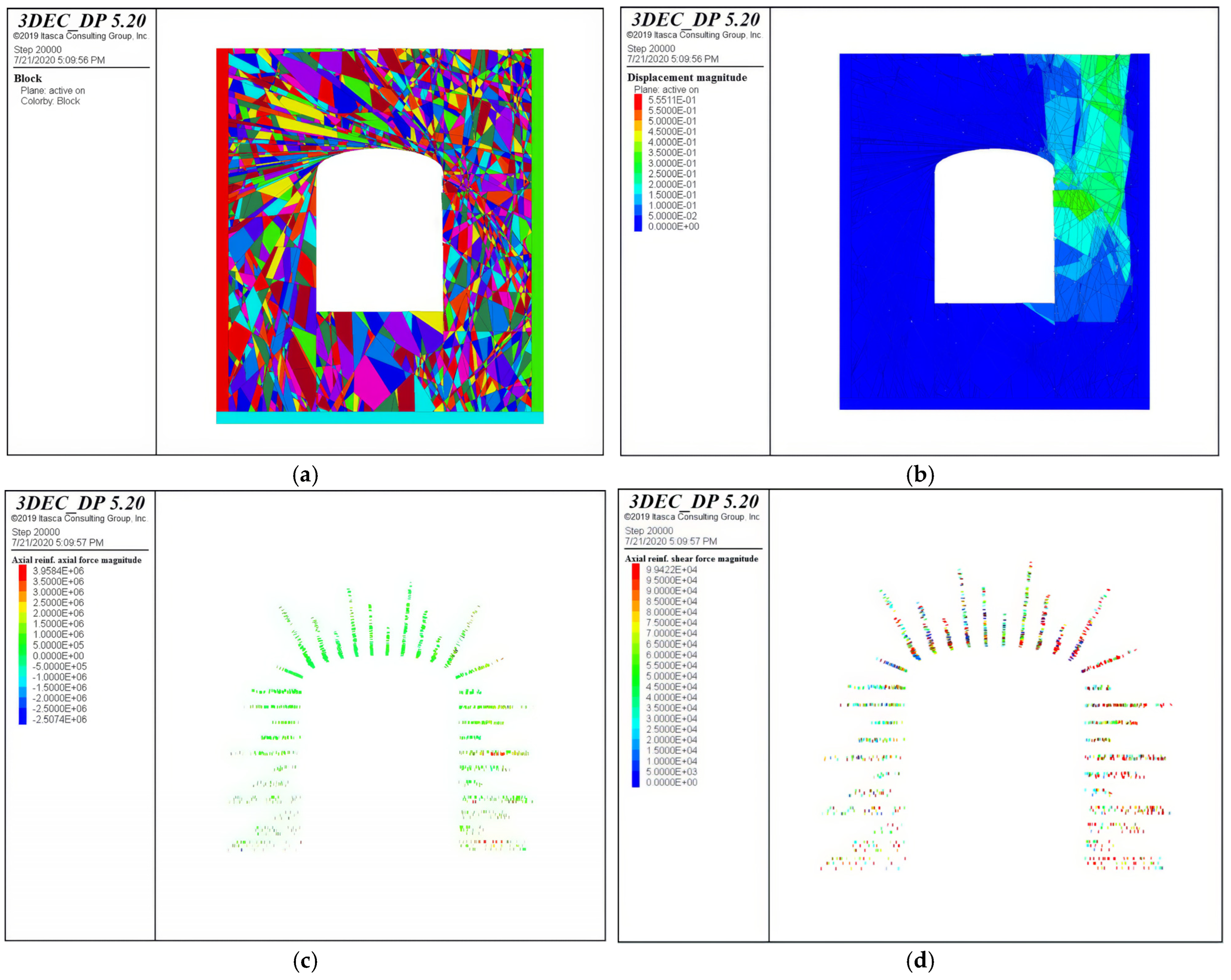
To investigate the failure of rock bolts due to excess displacement and induced stress, the axial force distribution along the rock bolts was examined. Figure 8 illustrates the displacement of blocks, along with the axial and shear force distribution of bolts, applying a support pattern (P17) on DFN7.

Figure 8.
(a) The generated DFN7 with the applied support pattern (P17); (b) the displacement magnitude; (c) axial force distribution magnitude; (d) shear force distribution magnitude.
According to Figure 8b, the displacements were mostly observed in the top-right section of the cavern with a magnitude of 10 to 40 cm, demonstrating the instability of the blocks in this section. As a result, applying the P17 support pattern to the DFN7 realization, the maximum axial force is experienced on the right and top right sections of the cavern (see Figure 8c), where the axial force values in this section exceed the ultimate and yield strength of the used rock bolts (482 kN), indicating a correlation between displacement and yielding rock bolts. However, Figure 8d shows that, unlike the axial force, the induced shear forces are less than 100 kN, which does not surpass the ultimate shear strength of the rock bolts.
Figure 9 illustrates the VT and V90 values for the equal bolt length patterns with 3, 6, and 9 m rock bolts. It is observed that an increase in the rock bolt length from three to six significantly decreases the total volume and size of the unstable blocks. However, a slight reduction is experienced by increasing the bolt length from 6 to 9 m. This reveals that the increase in bolt length after a specific length does not necessarily increase the stability of a structure in the jointed rock mass.
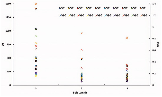
Figure 9.
The total unstable volume (VT) and volume of which 90% of unstable blocks are smaller (V90) variations against equal-length patterns with 3, 6, and 9 m bolt lengths for the ten DFN realizations.
Table 5 shows the most stable and unstable patterns across all DFN models. Generally, heavier patterns result in higher stability and stabilize more DFN realizations. For example, patterns 19 and 11 are the most stable and unstable, respectively, with pattern 19 being the heaviest and pattern 11 the lightest. However, as an exception, the highlighted pattern (P5) is one of the most effective patterns for stabilizing a single DFN realization with the worst stability condition. Another noteworthy point is that the two patterns, 8 and 9, with similar rock bolt consumption, experience a significantly different performance in DFN. This dichotomy can be explained by the random nature of the discrete fracture network and the arrangement of the joints. In a discrete fracture network, two bolting patterns with the same arrangement and spacing but different sections of bolt installation may show completely different results.
Table 5.
The most and least effective patterns, considering all DFN models.
Table 5 displays the rock bolt patterns that demonstrate the greatest stability, effectively stabilizing approximately 90% of the discrete fracture network (DFN) realizations. Among these patterns, P19 stands out with a total length of 17,442 m, making it the longest configuration. In comparison, each pattern of P12 and P17 has a total length of 11,628 m, while patterns P13 and P18 measure 14,535 m in total length. This data highlights the variations in rock bolt lengths across different configurations, emphasizing the importance of selecting the most effective pattern for optimal stabilization in geological applications. The differences in lengths suggest that, while some patterns may offer similar performance levels in terms of stabilization, their physical dimensions can vary significantly, which may influence the economic and logistical considerations during installation and maintenance.
Moreover, it is noteworthy that stabilization patterns P12 and P17, despite exhibiting a shorter cumulative length of bolting, incorporate bolts of triple length, whereas patterns P13 and P18, which demonstrate a greater cumulative length, utilize bolts of double length. This distinction implies that among the most efficacious stabilization patterns, those employing bolts of triple length may be more advantageous in terms of material efficiency and installation duration. The augmented length of the bolts in patterns P12 and P17 facilitates improved anchoring and support within the rock mass, potentially diminishing the necessity for supplementary bolting or reinforcement. Furthermore, the economic benefits associated with the utilization of triple-length bolts may extend beyond the initial costs of installation. By necessitating fewer bolts to achieve comparable or superior stabilization outcomes, there may be considerable reductions in labor expenses and time during the installation phase. Additionally, the diminished quantity of components can result in decreased maintenance obligations over time, thereby minimizing long-term operational expenditures.
The stability of blocks located in the unsupported section between the bolted sections was also investigated. As an example, the VT and V90 values for the ten DFN realizations in sections with and without rock bolt installation in P5 are illustrated in Figure 10. According to this figure, almost similar values are observed for VT and V90 in the installed rock bolt sections and the unsupported section intervals. It can be concluded that bolting not only stabilizes the blocks at bolted sections but also the blocks located in the section intervals. This phenomenon can be explained by the interlocked blocks due to the bolted section, providing the stability of the unbolted sections.
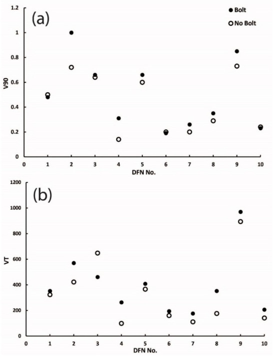
Figure 10.
(a) The volume of which 90% of unstable blocks are smaller (V90) and; (b) the total unstable volume (VT) variations against the ten DFN realizations for supported and unsupported sections.
Figure 11 illustrates the vertical displacement in blocks and axial force distributed in rock bolts for one most stable design patterns and one least stable design patterns, P12 and P5, respectively. The figure shows that, implementing both patterns, the top-right section is the dominant unstable zone of the cavern. However, by applying P12, no significant displacement is observed for the rest of the cavern zones, despite implementing the P5 pattern. This phenomenon can be explained by the axial force distributed in the rock bolts. For the P12 pattern, almost all of the bolts do not reach the yielding axial strength, whereas for the P5 pattern, most bolts on the left and right walls of the cavern exceeded the axial strength, displaying the instability of the blocks.
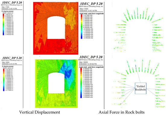
Figure 11.
Vertical displacement and axial force distribution in rock bolts implementing the best pattern P12 (top) and the worst pattern P5 (bottom).
Figure 12a illustrates the average and variation range of the VT and V90 values for the applied supporting patterns and the unsupported conditions for the DFN realizations. According to Figure 12b, in general, the support installation improves the stability of the cavern in all DFN realizations. However, there is a significant difference between the effectiveness of different patterns in different DFNs. The results illustrate that there are significant differences between the variation in the volume of the unstable blocks in the unsupported and supported cases. In other words, the installation of the support systems shrinks the volume range of unstable blocks and ensures that the volume of the unstable blocks is mostly in a smaller and specific range. Compared to conventional supporting systems and designing their patterns, patterns 6 and 11 have a moderately extended range of unstable block volume. Support system patterns 6 and 11 are the only patterns with an average V90 value of more than 0.5 m3. These two patterns are the lightest supporting systems, with 5814 and 3591 m of rock bolt consumption. In contrast, from support system patterns 3, 13, 18, and 19, the smallest range of total unstable block volumes was calculated. While 13, 18, and 19 are among the highest for rock bolt consumption, pattern 3 resulted in moderate bolt usage. This shows the importance of pattern arrangement while considering the economic criterion.

Figure 12.
The average and variation range of the volume of which 90% of unstable blocks are smaller (V90), (a) and total unstable volume (VT) (b) for the applied supporting patterns and the unsupported conditions (P0) for the DFN realizations. (c) The percentage confidence level for each pattern considering all DFN realizations.
Considering the number of stabilized DFN realizations obtained by the supporting patterns, Figure 12c illustrates the confidence level provided by each bolting pattern. According to the graph, pattern 11 has the lowest confidence level. This is due to its highest longitudinal spacing and the least total length of used rock bolts. The next pattern with the total length is pattern 6, which has a 50% confidence level. Patterns 2 and 5 have a 13% difference in bolt usage and deliver a 60% confidence level. To provide a 70% confidence level, patterns 4, 7, 9, 10, 15, and 16 can be utilized. Among these, pattern 10 has significantly lower (−30%) bolt consumption. With the same bolt length installation as the previous pattern group, 1, 3, 8, and 14 may provide 80% confidence. The highest confidence level is reached via patterns 12, 13, 17, 18, and 19, with a significantly high difference in bolt usage (up to 55%). Patterns 12 and 17 are the lightest. Unlike other patterns in this group, which have single or dual lengths, these two patterns have triple-length bolts. This shows that the total bolt length is not the only factor in selecting the most effective pattern. The bolt arrangement must also be considered.
A comprehensive procedure is presented to select the most effective rock bolt support pattern in the jointed rock mass. This is for stabilizing large underground constructions, considering the stochastic parameters of rock mass discontinuities using a DFN-DEM approach. The geometrical, geomechanical, and discontinuity characteristics of the CLAB2 cavern in Sweden were used for the analysis. Contrary to commonly used rock bolting methods, dual- and triple-length rock bolt patterns were also implemented, in addition to single-length patterns. Ten DFN realizations, along with 19 rock bolt support patterns, were examined before and after support installation, consisting of 200 cases (10 unsupported and 190 supported cases). The stability of each scenario is investigated by technical and financial criteria, including the total volume of unstable blocks (VT), the volume of which 90% of the unstable blocks are smaller (V90), and the rock bolt consumption.
The anchor bolt is a key point of tunnel design in a bedded rock mass. The previous theory of anchorage support does not fulfill engineering requirements, and the stability of bedded rock must be addressed by empirical methods. To investigate the bolt-anchoring performance for bedded rock mass under different anchoring methods, the rock failure mode under shear and tensile stresses was examined. The results showed that bolt anchoring for rock is achieved mainly through the bonded restoration of the surrounding rock near the drill holes using an anchoring agent. Additionally, the supporting resistance provided by the bolt body contributes to the anchoring. It was observed that the strength parameters of the bedded rock were increased under the anchoring effect. Full anchoring bolts were especially effective. In addition, it was observed that, without bolts, the failure mode changed from shear to split. In the case of bolting, the failure plane occurred parallel to the bolt’s axis. The shearing began along the interface between the hard and soft rock bedding. Compared to end bolt anchoring, full-length bolt anchoring was more effective. It provided a greater increase in the strength of the rock. Additionally, it enhanced the rock’s shear-bearing capacity. This ultimately enabled the rock to bear more load.
A parametric study was conducted to determine the influence of different bolt parameters (bolt length and diameter) on the maximum induced boundary displacements in a jointed rock mass. This was conducted by using a numerical method based on distinct element codes. For each joint type, the effect of variable bolt parameters on the tunnel boundary was studied in terms of total displacement. The simulation results confirmed that an increase in bolt length does not significantly reduce boundary displacement. However, an increase in bolt diameter substantially reduces tunnel boundary displacement. The finite-element analysis provided detailed insights into the deformation characteristics and stress distribution around the tunnel boundary. This highlighted the critical role of bolt diameter in enhancing tunnel stability.
The technical and economic criteria for the stability of each support system are inspected. Comparing the results from single-length rock bolt and multi-length rock bolt patterns shows that increasing the rock bolt length will improve the stability of the jointed rock mass to a certain length. Moreover, it is observed that multi-length rock bolt patterns with similar rock bolt consumptions result in significantly different stability conditions. These numerical results reveal the significance of the rock bolts’ arrangement and their properties. The stability of blocks between the longitudinal spacing of the rock bolting sections proves the presence of interlocked blocks in unsupported sections. This is due to the induced pressure from the supported sections.
3. Summary and Conclusions
A procedure is presented to select the most effective rock bolt support pattern in a jointed rock mass for stabilizing large underground constructions, considering the stochastic parameters of rock mass discontinuities using a DFN-DEM approach. The geometric, geomechanical, and discontinuity characteristics of the CLAB2 cavern in Sweden were used for the analyses. Contrary to commonly used rock bolting methods, in addition to single-length rock bolt patterns, dual- and triple-length rock bolt patterns were also implemented. Ten DFN realizations and 19 rock bolt support patterns were examined before and after support installation. This consisted of 200 cases: 10 unsupported and 190 supported cases. The stability of each scenario was investigated using technical and financial criteria. These included the total volume of unstable blocks (VT), the volume of which 90% of unstable blocks are smaller (V90), and the rock bolt consumption. The following conclusions are derived from the analyses.
- Examining the different DFN realizations with significant stability variation has shown that generating a single DFN realization does not represent the stability condition of an excavation in a jointed rock mass. Therefore, it cannot be considered for support design;
- By comparing single-length rock bolt patterns, it is shown that increasing the rock bolt length from 3 to 6 m enhances the stability significantly. Whereas the 9 m rock bolts result in comparable stability conditions to 6 m rock bolts. It can be concluded that increasing the rock bolt length may not necessarily improve the stability of jointed rock mass exceeding a certain length;
- The results show that a similar bolt consumption in a specific DFN realization may provide drastically different stability conditions. This reveals the importance of the bolting arrangement factor in stabilizing highly jointed underground constructions;
- It is observed that the blocks located between the supported section intervals became relatively stable. This reveals the presence of interlocked blocks in the bolting section intervals;
- It was concluded that, despite the commonly used equal-length rock bolt patterns, the best stability performance was generally observed for dual- and, further, for triple-length rock bolt patterns with equal rock bolt patterns;
- The previous studies mostly consider a regular arrangement of discontinuity or, ultimately, a single stochastic fracture network. Therefore, this study provides a systematic procedure for choosing the most effective supporting patterns. It considers various fracture network arrangements. It also takes into account technical and economic criteria based on the obtained confidence level.
Author Contributions
Conceptualization, A.A., H.H. and A.B.; methodology, A.A. and A.B.; software, N.S.I., M.B. and M.H.H.; validation, A.A. and M.B.; formal analysis; investigation, N.S.I. and M.B.; writing—original draft preparation, A.A. and N.S.I.; writing—review and editing, M.B. and H.B.M.; visualization, M.B. and H.B.M.; supervision, A.A., M.H.H. and A.B. All authors have read and agreed to the published version of the manuscript.
Funding
The authors declare that no funding was received for this work. Article Processing Charge costs were supported by Open Access-Publikationsfonds der CAU Universitätsbibliothek Kiel.
Data Availability Statement
The original contributions presented in the study are included in the article. Further inquiries can be directed to the corresponding author.
Conflicts of Interest
The authors declare no conflicts of interest.
References
- Das, R.; Sirdesai, N.N.; Singh, T.N. Analysis of deformational behavior of circular underground opening in soft ground using three-dimensional physical model. In Proceedings of the 51st US Rock Mechanics/Geomechanics Symposium, San Francisco, CA, USA, 25–28 June 2017. [Google Scholar]
- Dias, D. Convergence-confinement approach for designing tunnel face reinforcement by horizontal bolting. Tunn. Undergr. Space Technol. 2011, 26, 517–523. [Google Scholar] [CrossRef]
- Barton, P.I.; Pantelides, C.C. Modeling of combined discrete/continuous processes. AIChE J. 1994, 40, 966–979. [Google Scholar] [CrossRef]
- Bhasin, R.; Grimstad, E. The use of stress-strength relationships in the assessment of tunnel stability. Tunn. Undergr. Space Technol. 1996, 11, 93–98. [Google Scholar] [CrossRef]
- Vardakos, S.S.; Gutierrez, M.S.; Barton, N.R. Back-analysis of Shimizu Tunnel No. 3 by distinct element modeling. Tunn. Undergr. Space Technol. 2007, 22, 401–413. [Google Scholar] [CrossRef]
- Hudson, J.A.; Feng, X.T. Technical auditing of rock mechanics modelling and rock engineering design. Int. J. Rock Mech. Min. Sci. Geomech. Abstr. 2010, 47, 877–886. [Google Scholar] [CrossRef]
- Hoek, E.; Brown, E.T. Practical estimates of rock mass strength. Int. J. Rock Mech. Min. Sci. 1997, 34, 1165–1186. [Google Scholar] [CrossRef]
- Barton, N.; Lien, R.; Lunde, J.J.R.M. Engineering classification of rock masses for the design of tunnel support. Rock Mech. 1974, 6, 189–236. [Google Scholar] [CrossRef]
- Bieniawski, Z.T. Engineering classification of jointed rock masses. Civ. Eng. 1973, 12, 335–343. [Google Scholar]
- Barla, G.; Kovari, K.; Einstein, H.H. Manuscripts using numerical discrete element methods. Rock Mech. Rock Eng. 2013, 46, 655. [Google Scholar] [CrossRef]
- Das, R.; Singh, T.N. Effect of rock bolt support mechanism on tunnel deformation in jointed rockmass: A numerical approach. Undergr. Space 2021, 6, 409–420. [Google Scholar] [CrossRef]
- Maghous, S.; Bernaud, D.; Couto, E. Three-dimensional numerical simulation of rock deformation in bolt-supported tunnels: A homogenization approach. Tunn. Undergr. Space Technol. 2012, 31, 68–79. [Google Scholar] [CrossRef]
- Chao, T.Y. The Numerical Modelling of Rockbolts in Geomechanics by Finite Element Methods. Ph.D. Thesis, School of Information Systems, Computing and Mathematics, Brunel University, Uxbridge, UK, 1998. [Google Scholar]
- Li, A.; Li, Y.; Wu, F.; Shao, G.; Sun, Y. Simulation method and application of three-dimensional DFN for rock mass based on Monte-Carlo technique. Appl. Sci. 2022, 12, 11385. [Google Scholar] [CrossRef]
- Zhou, P.; Bazargan, M.; Lanaro, F.; Shirzadegan, S.; Nikadat, N.; Warema, S.; Yi, C.; Nordlund, E. Dynamic Modelling of Rock Bolts at Kiirunavaara Mine; BeFo: Stockholm, Sweden, 2024. [Google Scholar]
- Indraratna, B.; Kaiser, P.K. Design for grouted rock bolts based on the convergence control method. Int. J. Rock Mech. Min. Sci. Geomech. Abstr. 1990, 27, 269–281. [Google Scholar] [CrossRef]
- Carranza-Torres, C. Analytical and numerical study of the mechanics of rockbolt reinforcement around tunnels in rock masses. Rock Mech. Rock Eng. 2009, 42, 175–228. [Google Scholar] [CrossRef]
- Bobet, A. Elastic solution for deep tunnels: Application to excavation damage zone and rockbolt support. Rock Mech. Rock Eng. 2009, 42, 147–174. [Google Scholar] [CrossRef]
- Sakurai, S. Modeling strategy for jointed rock masses reinforced by rock bolts in tunneling practice. Acta Geotech. 2010, 5, 121–126. [Google Scholar] [CrossRef]
- Cai, Y.; Esaki, T.; Jiang, Y. A rock bolt and rock mass interaction model. Int. J. Rock Mech. Min. Sci. 2004, 41, 1055–1067. [Google Scholar] [CrossRef]
- Liu, J.; Yang, H.; Wen, H.; Zhou, X. Analytical model for the load transmission law of rock bolt subjected to open and sliding joint displacements. Int. J. Rock Mech. Min. Sci. 2017, 100, 1–9. [Google Scholar] [CrossRef]
- Ma, S.; Zhao, Z.; Nie, W.; Zhu, X. An analytical model for fully grouted rockbolts with consideration of the pre-and post-yielding behavior. Rock Mech. Rock Eng. 2017, 50, 3019–3028. [Google Scholar] [CrossRef]
- Noroozi, M.; Rafiei, R.; Bajolvand, M.; Hojati Tavandashti, A. Investigate the effect of rock mass joint intensity on performance of support systems in the tunnel by using DFN-DEM numerical modeling (Case study: The access tunnel of Rudbar Lorestan Dam plant). J. Anal. Numer. Methods Min. Eng. 2018, 8, 13–27. [Google Scholar] [CrossRef]
- Yokota, Y.; Zhao, Z.; Nie, W.; Iwano, K.; Okada, Y. Experimental and numerical study on the interface behaviour between the rock bolt and bond material. Rock Mech. Rock Eng. 2019, 52, 869–879. [Google Scholar] [CrossRef]
- Boon, C.W. Study of reinforcement support mechanisms for wide-span horse-shoe-shaped openings in horizontally layered jointed rock using the distinct element method. Rock Mech. Rock Eng. 2019, 52, 1179–1191. [Google Scholar] [CrossRef]
- Fu, X.; Sheng, Q.; Zhang, Y.; Chen, J. Investigations of the sequential excavation and reinforcement of an underground cavern complex using the discontinuous deformation analysis method. Tunn. Undergr. Space Technol. 2015, 50, 79–93. [Google Scholar] [CrossRef]
- Kong, C.; Yang, T.; Xiao, M.; Yuan, Q. Numerical simulation of fully grouted rock bolts with or without faceplates based on the tri-linear bond-slip model. Constr. Build. Mater. 2023, 367, 130288. [Google Scholar] [CrossRef]
- Li, D. A new analytical model for stress distribution in the rock bolt under axial loading. Int. J. Rock Mech. Min. Sci. 2024, 176, 105690. [Google Scholar] [CrossRef]
- Li, C.C.; Høien, A.H. The experimental determination of shear stress distribution along fully grouted rock bolts with different bond lengths subjected to pull testing. Int. J. Rock Mech. Min. Sci. 2023, 170, 105557. [Google Scholar] [CrossRef]
- Boon, C.W.; Houlsby, G.T.; Utili, S. Designing tunnel support in jointed rock masses via the DEM. Rock Mech. Rock Eng. 2015, 48, 603–632. [Google Scholar] [CrossRef]
- Li, C.C. A new energy-absorbing bolt for rock support in high stress rock masses. Int. J. Rock Mech. Min. Sci. 2010, 47, 396–404. [Google Scholar] [CrossRef]
- Yokota, Y.; Zhao, Z.; Shang, J.; Nie, W.; Date, K.; Iwano, K.; Okada, Y. Effect of bolt configuration on the interface behaviour between a rock bolt and bond material: A comprehensive DDA investigation. Comput. Geotech. 2019, 105, 116–128. [Google Scholar] [CrossRef]
- Li, S.; Yu, H.; Liu, Y.; Wu, F. Results from in-situ monitoring of displacement, bolt load, and disturbed zone of a powerhouse cavern during excavation process. Int. J. Rock Mech. Min. Sci. 2008, 45, 1519–1525. [Google Scholar] [CrossRef]
- Türkoğlu, M. Two-Dimensional Numerical Analysis of Tunnel Collapse Driven in Poor Ground Conditions. Master’s Thesis, Middle East Technical University, Ankara, Türkiye, 2013. [Google Scholar]
- Rao, R.V.; Naik, S.; Reddy, M.N.; Gupta, R.N. Discontinuum analysis and support design of road tunnels—A case study. In Geoecology and Computers; CRC Press: Boca Raton, FL, USA, 2000; pp. 141–150. [Google Scholar]
- Abdellah, W.R.; Ali, M.A.; Yang, H.S. Studying the effect of some parameters on the stability of shallow tunnels. J. Sustain. Min. 2018, 17, 20–33. [Google Scholar] [CrossRef]
- Zhou, F.; Sarfarazi, V.; Haeri, H.; Soleymanipargoo, M.H.; Fu, J.; Marji, M.F. A coupled experimental and numerical simulation of concrete joints’ behaviors in tunnel support using concrete specimens. Comput. Concr. 2021, 28, 189–208. [Google Scholar] [CrossRef]
- Nord, G.; Bagheri, M.; Baghbanan, A.; Stille, H. Design consideration of large caverns by using advanced drilling equipment. Felsbau 2007, 25, 131–136. [Google Scholar]
- Lanaro, F.; Fredriksson, A. Rock Mechanics Model-Summary of the Primary Data, Preliminary site description Forsmark area-version 1.2; Swedish Nuclear Fuel and Waste Management Co.: Stockholm, Sweden, 2005; SKB-R--05-83. [Google Scholar]
- Bazargan, M.; Gudmundsson, A. Dike-induced stresses and displacements in layered volcanic zones. J. Volcanol. Geotherm. Res. 2019, 384, 189–205. [Google Scholar] [CrossRef]
- Bazargan, M.; Gudmundsson, A. Stresses and displacements in layered rocks induced by inclined (cone) sheets. J. Volcanol. Geotherm. Res. 2020, 401, 106965. [Google Scholar] [CrossRef]
- Khoei, A.R.; Hirmand, M.; Vahab, M.; Bazargan, M. An Enriched FEM Technique for Modeling Hydraulically Driven Cohesive Fracture Propagation in Impermeable Media with Frictional Natural Faults: Numerical and Experimental Investigations. Int. J. Numer. Methods Eng. 2015, 104, 439–468. [Google Scholar] [CrossRef]
- Bazargan, M.; Berg, S.; Bergholm, A.; Moallemi, S.; Machado, B. Exploring the impact of shallow tunneling in fractured rock masses with pre-existing tunnels: A case study. In Tunnelling into a Sustainable Future—Methods and Technologies; CRC Press: Boca Raton, FL, USA, 2025. [Google Scholar] [CrossRef]
- Li, C.C. Principles of rockbolting design. Rock Mech. Rock Eng. 2017, 9, 396–414. [Google Scholar] [CrossRef]


Disclaimer/Publisher’s Note: The statements, opinions and data contained in all publications are solely those of the individual author(s) and contributor(s) and not of MDPI and/or the editor(s). MDPI and/or the editor(s) disclaim responsibility for any injury to people or property resulting from any ideas, methods, instructions or products referred to in the content. |
© 2025 by the authors. Licensee MDPI, Basel, Switzerland. This article is an open access article distributed under the terms and conditions of the Creative Commons Attribution (CC BY) license (https://creativecommons.org/licenses/by/4.0/).