Abstract
A reinforced earth wall is a structure in which reinforcement materials are placed in an embankment to build a vertical or nearly vertical wall surface. Such walls have been widely used in roads and in developed land since around 1960. Reinforcement materials have a set service life of 100 years and fall into two types: steel and geosynthetics. To ensure long-term durability, steel reinforcement materials are plated, while geosynthetics are designed with a limit strength designed to resist fracture for 100 years under the conditions of a given load placed on the reinforcement materials. However, owing to the difficulty of assessing the condition of reinforcement materials in soil, this paper proposes solutions based on non-destructive methods. Specifically, it proposes a method of assessing the amount of strain through an embedded optical fiber in the case of geosynthetic reinforcement materials, or magnetic surveying to investigate the degree of corrosion in the case of steel reinforcement materials. This paper demonstrates that it is possible to non-destructively assess the state of either type of reinforcement material.
1. Introduction
A reinforced earth wall is a structure in which reinforcement materials are placed in an embankment to build a vertical or nearly vertical wall surface. The form in current use was developed around 1960, and is used in many roads and developed land sites. Two types of reinforcement materials are mainly used: steel materials and polymeric materials, known as geosynthetics. The reinforcement is buried in the soil and maintains the vertical concrete wall connected to the reinforcement by the friction between the soil and the reinforcement, and the tensile strength of the reinforcement itself. The concepts behind their designs appear in the standards and manuals of different countries [1,2,3,4]. The service life of the materials is considered to be 100 years. To ensure functionality over the period of service life, aspects of long-term durability, such as corrosion in steel reinforcement materials and physical and chemical stability in geosynthetic reinforcement materials, must be guaranteed.
To ensure this 100-year durability, steel reinforcement materials are coated with a specified amount of plating to prevent corrosion. Geosynthetic reinforcement materials are considered to be chemically stable because the ultraviolet rays that are a cause of deterioration do not penetrate the soil. In terms of physical stability, geosynthetics are designed with a limit strength (creep rupture strength) that will resist fracture for 100 years under the given load placed on the reinforcement materials.
Over 60 years have passed since the development of reinforced earth walls, and it is clear that the number of walls approaching the end of their service lives will increase in the future. In the maintenance and management of road structures, including reinforced earth walls, it is essential to conduct inspections, diagnoses, and necessary measures as part of a maintenance cycle. In Japan today, the number of reinforced earth walls is vast. For example, in road inspections, the standard approach is to visually detect the early signs of deterioration through routine patrols [5]. However, visual inspections cannot assess the condition of the reinforcement materials inside the reinforced earth walls. Furthermore, collapses caused by the rupture of reinforcement materials often occur suddenly, with little or no prior indication of deformation. These sudden collapses can result in wall panels falling and potentially causing human casualties. Once reinforcement materials are embedded in reinforced earth walls, only the concrete surface of the wall can be examined. In other words, it is nearly impossible to ascertain the condition of the reinforcement materials, and the routine inspections carried out regularly are unlikely to detect any signs of internal deformation.
This paper discusses methods for assessing the state of geosynthetic and steel reinforcement materials in soil without the destruction of structures. These methods must be considered according to the type of reinforcement material. Because physical stability is a problem with geosynthetic reinforcement materials, it is important to assess the amount of strain occurring in them. This study demonstrates that long-term observation is possible by embedding optical fibers in the geosynthetics. In the case of steel reinforcement materials, because corrosion affects stability, it is important to assess the degree of corrosion. Here, magnetic surveying is considered as a new method of non-destructive surveying. This paper shows the potential for assessing corrosion through magnetic surveying, as seen from basic research.
2. Materials and Methods
2.1. Polymeric Reinforcement Materials (Geosynthetics)
In assessing the physical stability of geosynthetics, the amount of strain in the soil must be known. If the amount of strain generated is equivalent to the limit strength, then there is a possibility that fractures will occur before the end of the service life.
Strain gauges have traditionally been used to measure the strain in geosynthetics. A strain gauge measures changes in electrical resistance. However, in moisture-rich environments within the soil, the durability of a strain gauge is limited to about 10 years at most due to issues like wiring corrosion and adhesive degradation. Based on my experience, failures can occur even sooner.
To address this, a structure in which optical fibers are embedded in geosynthetics to enable the measurement of strain has been developed [6]. As shown in Figure 1, this geosynthetic consists of a high-elasticity aramid fiber covered in a grid pattern with high-density polyethylene, with the strength provided by the aramid fiber. By replacing one of the aramid fibers with an optical fiber, it becomes possible to measure the strain occurring in the geosynthetics. The measurement of the strain occurring in the optical fiber uses Brillouin optical time-domain reflectometry (BOTDR) [7]. This measurement method takes advantage of the phenomenon by which bending and subtle fluctuations in density in the optical fiber generate scattered light, a portion of which returns as reflected light. The spectrum of this reflected light is known to shift and change in proportion to the amount of strain in the optical fiber [8]. Considering the service life of the optical fibers generally used for communications, it may be possible to perform measurements for a longer period of time. The ability to measure the distribution of strain over the total length of the optical fiber is also a major advantage over strain gauges that are capable of measurement only over a localized range of several millimeters. The effectiveness of this, as observed in the past cases of measurement, is shown here.
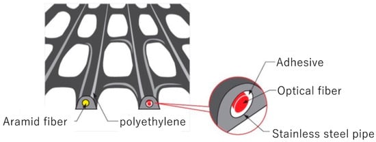
Figure 1.
Geosynthetics with embedded optical fiber.
2.2. Steel Reinforcement Materials
SS400, a rolled steel used for general structures (JIS G 3101) [9], is used as a steel reinforcement material. It generally exhibits greater mechanical strength and toughness than geosynthetics and is more physically stable. To combat the corrosion that affects the service life of steel reinforcement materials, the material is galvanized to achieve a 100-year service life [1]. Visual inspection is the most effective means of assessing the state of corrosion; however, this is extremely difficult in the case of reinforced earth walls as the material is buried in soil.
We applied non-destructive investigation methods for the study of corrosion in steel reinforcement materials without unearthing them. This investigation method may greatly contribute to the maintenance of these materials, and also may become the necessary approach for identifying corrosion before specific damage occurs. To monitor the progress of corrosion in underground steel, electromagnetic surveying methods are effective. The primary survey methods include electrical surveying (using specific electrical resistance), ground penetration radar (using relative permittivity), and magnetic surveying (using magnetic properties). Among these, magnetic prospecting is the most suitable for monitoring the corrosion process of underground steel materials because it is not affected by changes in the soil moisture content or ground temperature [10,11].
Then, we used a magnetic survey method for the non-destructive assessment of the state of corrosion in steel reinforcement materials buried in the ground. Sakai et al. [12,13] conducted a magnetic survey at an ancient tomb in Japan and successfully identified a rusted sword buried 1.5 m underground, providing a valuable reference for this study.
Changes in magnetism in steel objects were studied using corrosion experiments performed in the laboratory, while the effectiveness of methods using the non-contact magnetic surveying of the state of corrosion from the surface of the ground was investigated using experiments performed in the field.
2.2.1. Laboratory Corrosion Experiment
Generally, the magnetic properties of a material consist of remanent magnetization and induced magnetization. Ferromagnetic materials, such as steel, acquire remanent magnetization, which functions as a form of permanent magnetism. Induced magnetization arises in a material when an external magnetic field is applied, and it is quantified by the magnetic susceptibility, which is the ratio of the induced magnetization to the applied magnetic field intensity. In the case of steel, as investigated in this study, magnetic surveys primarily measure the magnetic field resulting from remanent magnetization.
This study determined the remanent magnetization by measuring the magnetic field of test specimens using a flux-gate magnetometer (Applied Physics Systems, Model 520, Mountain View, CA, USA) within a magnetically shielded box to eliminate external magnetic field interference. The induced magnetization (magnetic susceptibility) was analyzed using a Bartington MS2 magnetometer. By measuring these two types of magnetizations, the study was able to quantify changes in magnetism associated with steel corrosion.
In the laboratory experiment, a sample of SS400 steel (50 × 60 × 4 mm) was used. Corrosion was promoted through both the application of a corrosion accelerant (Figure 2) and electrolytic corrosion (Figure 3), after which changes in the magnetism of the steel were compared.
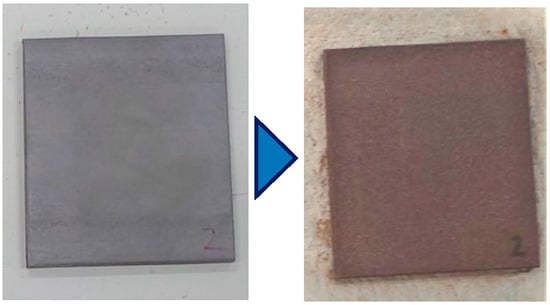
Figure 2.
State of corrosion due to corrosion accelerant (using a 10% aqueous solution of inorganic halides).
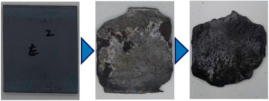
Figure 3.
States of corrosion due to electrical corrosion.
2.2.2. Field Experiment
Based on the data from the laboratory experiment, we conducted a field experiment to reproduce the state of corrosion. Portions of the steel reinforcement (1160 × 60 × 4 mm) were subjected to defects or severing, as shown in Figure 4. These were placed on the ground surface, and the magnetic field (magnetic flux density) was measured directly above the steel along the survey line using the optically pumped magnetometer (Geometrics, San Jose, CA, USA, G-858G) (Figure 5). The objective was to compare the magnetic fields of new reinforcement materials and reinforcement materials with defects simulating corrosion in order to understand the relationship between corrosion and the magnetic field.
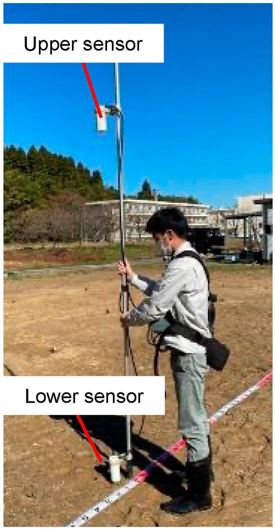
Figure 4.
Magnetic field measurement using an optically pumped magnetometer.
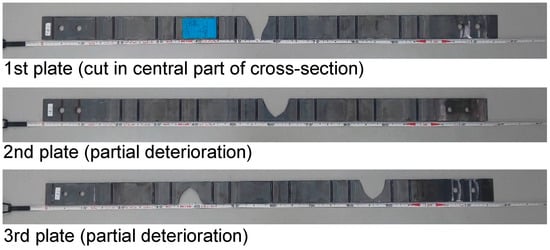
Figure 5.
Steel plates in which deterioration due to corrosion was simulated.
Additionally, new reinforcement materials were buried at different depths (0.5, 0.75, and 1.0 m) underground (Figure 6), and the magnetic field was measured from the surface. The objective was to determine whether it was possible to measure the magnetic field in buried conditions, and to establish the effective measurement range. Two types of reinforcement materials—one with anti-corrosion treatment (zinc galvanization) and one without—were buried at the same depths. Regular measurements will be conducted in the future to compare and verify the results based on the presence or absence of anti-corrosion treatment over the long term.
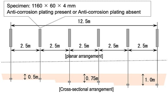
Figure 6.
Arrangement of iron plates in burial experiments.
3. Results
3.1. Measurement of the Amount of Strain in Geosynthetic Reinforcement Materials
To assess the long-term stability of geosynthetic reinforcement materials, the amount of strain must be known. In the past, measurements from optical fibers and from strain gauges have been compared [14]. In this study, measurements were performed on a reinforced earth wall (wall height: 9.5 m), as shown in the cross section in Figure 7, from the construction stage onward. The strain immediately after the placement of the reinforcement materials was measured as the initial value, and the changes in the strain during the process of embanking were measured. The results for a reinforcement material 6.0 m in length, placed at a height of 2.25 m from the base of the reinforced earth wall, are shown in Figure 8. The surface of the wall lies at the origin. The value immediately after the placement on 7 March 2005 is taken as the initial value (0%). The subsequent increases in strain are shown. A comparison of the values between 12 March and 15 June (when the embankment was completed) reveals an overall trend in increasing strain. The tensile force applied to the geosynthetics increases as the embankment increases in height. It can also be seen that the distribution of strain measured using a strain gauge and the distribution profile obtained using optical fibers are slightly different. While strain gauges measure local strain over an area of approximately 10 mm, with measurements spaced at 1.5 m intervals and unable to capture strain between the gauges, optical fibers measure the average strain over 1 m intervals, shifting the measurements by 0.2 m increments. Strain gauges capture point measurements locally, while optical fibers allow for continuous linear measurement. This difference in measurement methods is thought to cause the variation in distribution profiles.
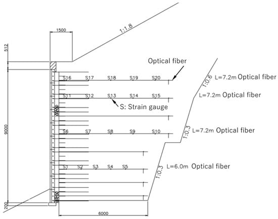
Figure 7.
Cross section of a reinforced earth wall with geosynthetics [14].
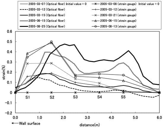
Figure 8.
Distribution of strain in geosynthetics (L = 6.0 m optical fiber and S1–5 strain gauge) [14].
3.2. Change in Magnetism Caused by Corrosion in Steel Reinforcement Materials
Using magnetic surveying to non-destructively assess the degree of corrosion in steel reinforcement materials, the change in magnetism in steel objects was studied in corrosion experiments performed in the laboratory. The effectiveness of the methods for the non-contact surveying of the state of corrosion, performed at the ground surface, was investigated using experiments performed in the field.
3.2.1. Results of the Laboratory Corrosion Experiment
In the laboratory experiment, steel samples were subjected to corrosion using two methods, and the changes in magnetism were investigated. In the samples to which corrosion accelerant was applied, corrosion occurred only on the surfaces of the steel samples, and no significant results were obtained. Conversely, in the case of electrolytic corrosion, both the magnetic susceptibility and the remanent magnetization exhibited decreasing trends associated with the decrease in volume (mass) as a result of corrosion, as shown in Figure 9. In other words, when volume greatly decreased as a result of corrosion (e.g., corrosion resulting in defects in the cross section of the material), changes in the magnetism were confirmed, and magnetic surveying was presumed to be effective.
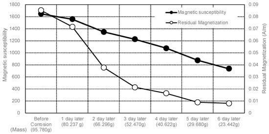
Figure 9.
Reduction in magnetization due to volume (mass) reduction.
3.2.2. Results of the Field Experiment
Steel reinforcement material used in actual reinforced earth walls was placed on the surface of the ground and magnetic surveying was performed. The maximum and minimum values for reverse polarity occurred near both ends of the belt-shaped steel reinforcement material (plate), as shown in Figure 10. It was also found that the maximum and minimum values (absolute values) decreased when defects were introduced into the reinforcement material to simulate corrosion. Measurements were taken using three reinforcement materials, and similar trends were obtained. Figure 10 shows the results for the third plate. Defects of varying sizes were simulated on the three reinforcement materials. As shown in Figure 11, the maximum and minimum values (absolute values) decreased in accordance with the decreases in volume (mass) caused by the defects, as in the results of the laboratory experiment. However, the degree of decrease (i.e., the slope of the graph) was not uniform, and differences between the samples were observed. Further verification is required to formulate the relationship between the volume and the magnetic flux density, and to identify the locations of the defects from the measured values of the magnetic fields.
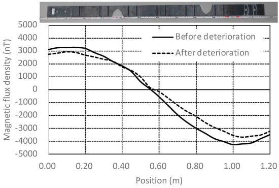
Figure 10.
Magnetic field (magnetic flux) of 3rd plate.
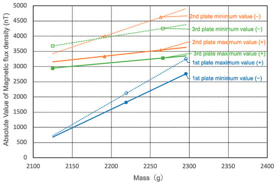
Figure 11.
Changes in magnetic flux density with mass.
In the experiment in which the steel reinforcement material was buried, similar to the one in which it was placed on the ground surface, the maximum and minimum values for reverse polarity were confirmed near both ends of the steel reinforcement material, as shown in Figure 12. A tendency toward lower values when the steel reinforcement material was buried more deeply was observed. Thus, the effectiveness of magnetic surveying for buried materials is demonstrated.
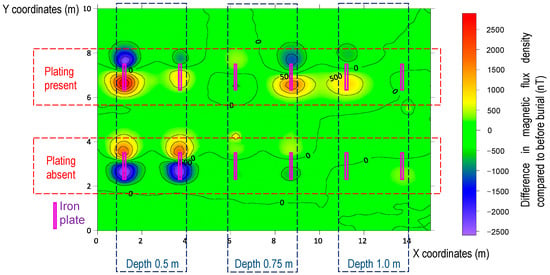
Figure 12.
Distribution of magnetic flux density in buried iron plates.
4. Discussion
This study examined methods for investigating the long-term stability of reinforcement material in reinforced earth walls according to the type of material. Because physical stability is a problem with geosynthetic reinforcement materials, it is important to assess the amount of strain occurring in them. This study demonstrated that long-term observation is possible by embedding optical fibers in the geosynthetics. The most significant feature of using optical fiber for strain measurement is that it uses values along a contiguous fiber rather than values at points, as in the case of the measurement using strain gauges. If a fracture occurs in the reinforcement material, then the optical fiber will be fractured as well, and further measurement will be impossible, which also makes this method effective in the identification of the point of fracture.
With regard to steel reinforcement materials, changes in the magnetism associated with corrosion were studied in the laboratory, and the effectiveness of methods using magnetic surveying for the non-contact surveying of the state of corrosion from the surface of the ground was investigated using experiments performed in the field. From these, the following points were confirmed:
- In the case of the shallow, surface-only corrosion of steel reinforcement material, a change in magnetization could not be confirmed;
- In the case of corrosion in which the volume of steel reinforcement material decreases, it was confirmed that magnetization in the steel reinforcement material decreases in accordance with the decrease in the volume;
- It was confirmed that the maximum and minimum values of the magnetic fields at the ends of the material change with decreases in the volume of the steel reinforcement materials;
- Even when steel reinforcement materials were placed in the ground, it was possible to confirm magnetic fields and their maximum and minimum values.
From the above, it was concluded that magnetic surveying is effective in the non-destructive investigation of corrosion in steel reinforcement materials in the ground. The authors will conduct further verification to establish a method for the identification of the locations of defects and will investigate long-term changes in steel reinforcement materials buried in the ground.
5. Conclusions
This study has demonstrated the potential of non-destructive methods for assessing the condition of reinforcement materials in the soil, focusing on both geosynthetic and steel reinforcement materials.
For geosynthetic reinforcement materials, the embedded optical fiber technique proved effective for long-term strain monitoring. This method offers a significant advantage over traditional strain gauges by providing distributed strain measurements along the entire length of the reinforcement. The results showed that optical fibers could continuously monitor changes in strain, which is crucial for maintaining the structural integrity of reinforced earth walls over their service life. This method’s ability to detect points of fracture provides valuable insight for the early detection of potential failures.
For steel reinforcement materials, magnetic surveying was evaluated as a non-destructive technique to assess corrosion. The study confirmed that magnetic surveying is effective for detecting the changes in magnetism associated with corrosion, particularly when there is a significant reduction in volume due to corrosion. The laboratory and field experiments demonstrated that changes in the magnetic flux density correlate with the extent of corrosion, even for buried steel reinforcement materials. However, the sensitivity of this technique decreases with depth, suggesting it is most effective for shallow applications. For shallow measurements, it is believed that sufficient measurements can be obtained by conducting the survey from the wall panels to which the reinforcement is attached. The measurement method from the wall side will be verified in future.
In summary, the embedded optical fiber technique and magnetic surveying method offer promising solutions for the non-destructive assessment of reinforcement materials in soil. These methods have the potential to significantly enhance the maintenance and management of reinforced earth structures, ensuring their long-term stability and safety. Further research is recommended to refine these techniques and to establish standardized procedures for their application in real-world scenarios.
Author Contributions
Conceptualization, N.T. and H.S.; methodology, N.T. and H.S.; validation, N.T. and H.S.; investigation, N.T.; resources, N.T. and H.S.; data curation, N.T. and H.S.; writing—original draft preparation, N.T.; writing—review and editing, N.T. and H.S.; visualization, N.T.; supervision, H.S.; project administration, N.T.; funding acquisition, N.T. All authors have read and agreed to the published version of the manuscript.
Funding
This research was conducted with the support of a grant from JSPS KAKENHI, Grant Number JP 20K04639.
Data Availability Statement
The raw data supporting the conclusions of this article will be made available by the authors on request.
Acknowledgments
We thank Yusuke Katayama for his contribution, and Takehiko Nitta and other members of the Japan Terre-Armée Association for their valuable advice. We sincerely express our gratitude.
Conflicts of Interest
The funders had no role in the design of the study; in the collection, analyses, or interpretation of data; in the writing of the manuscript; or in the decision to publish the results.
References
- Public Works Research Center. Design and Construction Manual for Reinforced Earth Wall (Terre Armee), 4th Revised ed.; Public Works Research Center: Tokyo, Japan, 2014. [Google Scholar]
- Public Works Research Center. Design and Construction Manual for Reinforced Soil Using Geotextiles, 2nd Revised ed.; Public Works Research Center: Tokyo, Japan, 2013. [Google Scholar]
- Standard Specifications for Highway Bridges, 17th ed.; American Association of State Highway and Transportation Officials: Washington, DC, USA, 2002.
- Elias, V.; Christopher, B.R.; Berg, R.R. Mechanically Stabilized Earth Walls and Reinforced Soil Slopes Design and Construction Guidelines; NHI Course No. 132042; Federal Highway Administration: Washington, DC, USA, 2001; pp. 73, 114–116.
- Japan, Ministry of Land, Infrastructure, Transport and Tourism. Inspection Guidelines for Road Earthwork Structures; Ministry of Land, Infrastructure, Transport and Tourism, Roads Bureau, National Roads and Engineering Division: Tokyo, Japan, 2023.
- Cao, J.; Yokota, Y.; Tatuta, N. The performance confirmation test of geogrid with sensor function. Geosynth. Eng. J. 2003, 18, 207–210. [Google Scholar] [CrossRef]
- Horiguchi, T.; Shimizu, K.; Kurashima, T.; Tateda, M.; Koyamada, Y. Development of a distributed sensing technique using Brillouin scattering. IEEE J. Light. Technol. 1995, 13, 1296–1302. [Google Scholar] [CrossRef]
- Horiguchi, T.; Kurashima, T.; Tateda, M. A technique to measure distributed strain in optical fibers. IEEE Photonics Technol. Lett. 1990, 2, 352–354. [Google Scholar] [CrossRef]
- JIS G 3101; Rolled Steels for General Structure, Japanese Industrial Standard. Japan Standards Association: Tokyo, Japan, 2010.
- Clark, O.A.; Clark, A. Seeing Beneath the Soil: Prospecting Methods in Archaeology; B. T. Batsford Ltd.: London, UK, 1990. [Google Scholar]
- Public Interest Incorporated Association Geotechnical Engineering Society. Methods and Explanations of Soil Investigation; Public Interest Incorporated Association Geotechnical Engineering Society: Tokyo, Japan, 2013. [Google Scholar]
- Hideo, S.; Naruhiro, N.; Yoshinori, I.; Naoki, T. Evaluation of Non-Destructive Radar and Magnetic Surveys for Detecting Iron Burial Objects in Ancient Tombs. Proc. Jpn. Soc. Inf. Data Sci. Archaeol. 2022, 25, 41–44. [Google Scholar]
- Sakai, H.; Kurosawa, N.; Tanaka, Y.; Uno, T. Electromagnetic Survey at Zobisan Front and Rear Tombs at Gifu Prefecture, in “Zobisan Front and Rear Tombs”; Shinyosha: Tokyo, Japan, 1997; pp. 53–64. [Google Scholar]
- Tatta, N.; Yoshida, K.; Yokota, Y.; Yashima, A. Field tests of the geogrid with optical fiber. Geosynth. Eng. J. 2005, 20, 305–308. [Google Scholar] [CrossRef]
Disclaimer/Publisher’s Note: The statements, opinions and data contained in all publications are solely those of the individual author(s) and contributor(s) and not of MDPI and/or the editor(s). MDPI and/or the editor(s) disclaim responsibility for any injury to people or property resulting from any ideas, methods, instructions or products referred to in the content. |
© 2024 by the authors. Licensee MDPI, Basel, Switzerland. This article is an open access article distributed under the terms and conditions of the Creative Commons Attribution (CC BY) license (https://creativecommons.org/licenses/by/4.0/).