Article

A Crawling Soft Robot Driven by Pneumatic Foldable Actuators Based on Miura-Ori

1
College of Mechanical and Electrical Engineering, Beijing University of Chemical Technology, Beijing 100029, China
2
Qian Xuesen Laboratory of Space Technology, Beijing 100094, China
*
Authors to whom correspondence should be addressed.
Actuators 2020, 9(2), 26; https://doi.org/10.3390/act9020026
Submission received: 5 March 2020 / Revised: 4 April 2020 / Accepted: 6 April 2020 / Published: 9 April 2020
(This article belongs to the Special Issue Pneumatic Soft Actuators)

Abstract

:
Origami structures are highly demanded for engineering applications. Using origami folding to design and actuate mechanisms and machines offers attractive opportunities. In this paper, we design a crawling robot driven by pneumatic foldable actuators (PFAs) based on Miura-ori, according to the parallel foldable structure and different control patterns, which can perform different movements. The PFA inspired from Miura-ori is composed of a folding part, transition part, and sealing part, made by flexible materials and a paper skeleton. This actuator can obtain a large deformation by folding under negative pressure due to its own characteristics, and the relationship between deformation and pressure is analyzed. According to the different folding and unfolding times of left and right actuators, the crawling robot can perform both linear and turning movements. The speed of the robot is about 5 mm/s and it can turn at a speed of about 15°/s. The crawling robot uses the ability of the foldable structure to cope with the challenges of different environments and tasks.

1. Introduction

Compared with rigid robots, soft robots are made of intrinsically soft and/or extensible materials that can deform and absorb much of the energy arising from collisions [1]. Soft robots have great potential in detecting; they can change their shape actively [2] or passively [3] to enter confined spaces.
In recent years, the form and movement modes of soft robots have obtained inspiration from soft animals such as earthworms [4,5], caterpillars [6], snakes [7,8], and octopuses [9,10,11]. A soft robot usually can complete movements such crawling [12,13,14,15,16], rotating [6], swimming [8,17], jumping [18], and climbing [13,19] by functional structure designs and periodic controls.
Origami structures have many applications in robot designs [20]. Using origami folding to construct and actuate mechanisms and machines offers attractive opportunities from small, scalable, and cheap robots to deployable adaptive structures [21]. Based on the Kresling origami structure, Pagano et al. designed a crawling robot that performs both linear and turning movements [21]. Jeong et al. designed a cable-driven three-finger robot based on the twisted tower origami structure, which has the potential to grab fragile items [22]. Fang et al. designed an earthworm-like robot based on an origami ball that could achieve effective locomotion [23]. Lee et al. proposed a novel design for a variable-diameter wheel based on the spherical waterbomb tessellated pattern [24]. Martinez et al. designed an elongation actuator with paper folded into a bellows-like pattern [25].
In this article, first, we design pneumatic foldable actuators (PFAs) based on Miura-ori. Then, we design a crawling soft robot driven by the PFAs. This robot consists of the PFAs, front feet, and rear feet, most of which are made of flexible materials and a small part made by printing paper. According to the parallel structure and different control patterns, this robot can perform both linear and turning movements. Because of its turning motion ability, it can avoid obstacles. Due to its soft structure, it has the potential to be applied to a complex and varied natural environment.

2. Inspiration from Miura-Ori

Miura folding is a folding technique invented by Kogyo Miura [26]. The Miura fold pattern gives paper interesting mechanical and material properties. For example, Miura folding gives seemingly unremarkable paper greater stiffness, compressibility, and contractile ability, known as a negative Poisson ratio [27]. Miura folding is considered shape-memory origami because the sheet can easily be re-folded and returned to its compact shape after unfolding [28]. Miura folding also has the potential to give materials new properties [27,29,30].
Figure 1a shows a Miura-ori pattern; the red lines represent ‘‘mountain’’ creases that remain on the top after folding. The blue lines represent ‘‘valley’’ creases that remain on the bottom after folding. Figure 1b shows the corresponding folded state. The Miura-ori pattern is a periodic structure; its unit consists of four parallelograms, and the parameters are shown in Figure 1c. In each parallelogram, the short side of the length is a, the long side of the length is b, the acute angle is β ∈ [0°, 90°], the and projection angle between two ridges is θ ∈ [0°, 2β]. The projection angle θ can be used to characterize the folding of the unit cell of Miura-ori, with θ = 2β for the planar state and θ = 0° for the completely collapsed state [27,30].

2.1. Design of the Pneumatic Foldable Actuator

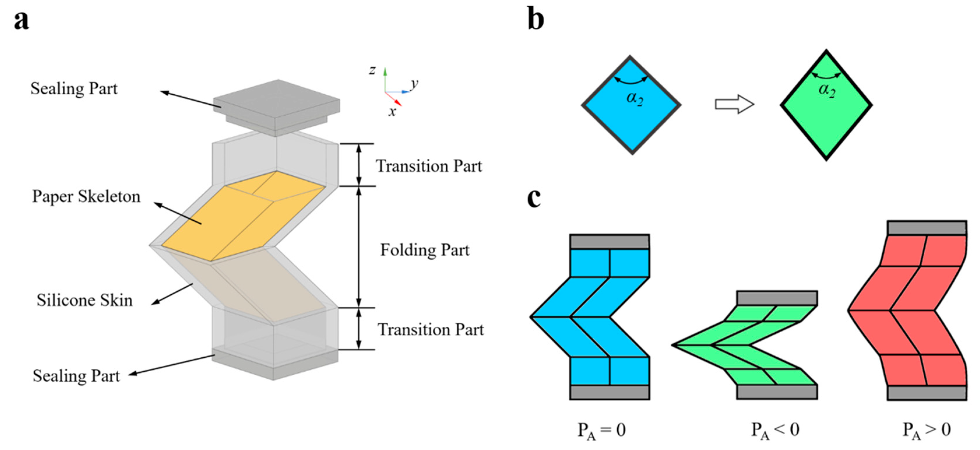
The PFA is composed of a foldable part, transition part, paper skeleton, and sealing part (Figure 2a). The foldable part is composed of two Miura-ori units combined up and down made by silicone, just like part of the Miura-ori tube, and paper skeletons are glued to the silicone skin. Transition parts are added at the front and rear ends of the foldable part. Sealing parts are glued on the top of the transition part to ensure airtightness of the PFA, and it can be made into different shapes according to different requirements.
The design parameters of the foldable part and transition part are summarized and shown in Table 1; parameters not listed can be obtained by calculation [27,30]. PA is the pressure of the PFA. Moreover, the foldable part is in the process of folding; α2 will change, and the cross-section of the foldable part parallel to the x-y plane will change from a square to a parallelogram (Figure 2b). However, the shape of the sealing part is not changed and will hinder the deformation in the folding process of the foldable part. The transition part between the foldable part and sealing part can reduce the obstruction produced by the sealing part while folding.
The PFA has two different states under negative pressure and positive pressure. The folding state of the PFA under negative pressure is shown in Figure 2c. It can reduce its length along the z-direction by folding due to the characteristics of the foldable part based on Miura-ori. Figure 2c also shows the inflation state of the PFA under the positive pressure; the PFA can extend its length due to material properties of the transition part along the z-direction.

2.2. Theoretical Modeling of the PFA

We present theoretical modeling of the PFA. As mentioned before, the PFA can achieve linear motion along the z-direction under different air pressure. A static analysis is established to understand the relation between the PA and corresponding deformation based on Miura-ori tubes. According to the equations of Miura-ori [27,30]:
l = 2 b sin ( θ 2 ) w = 2 a cos β cos ( θ 2 ) h = a sin 2 β sin 2 ( θ / 2 ) cos ( θ / 2 )
θ , w , h can be calculated as:
θ = a r c s i n ( l / 2 b ) w = 4 a b c o s β 4 b 2 l 2 h = a 4 b 2 s i n 2 β l 2 4 b 2 l 2
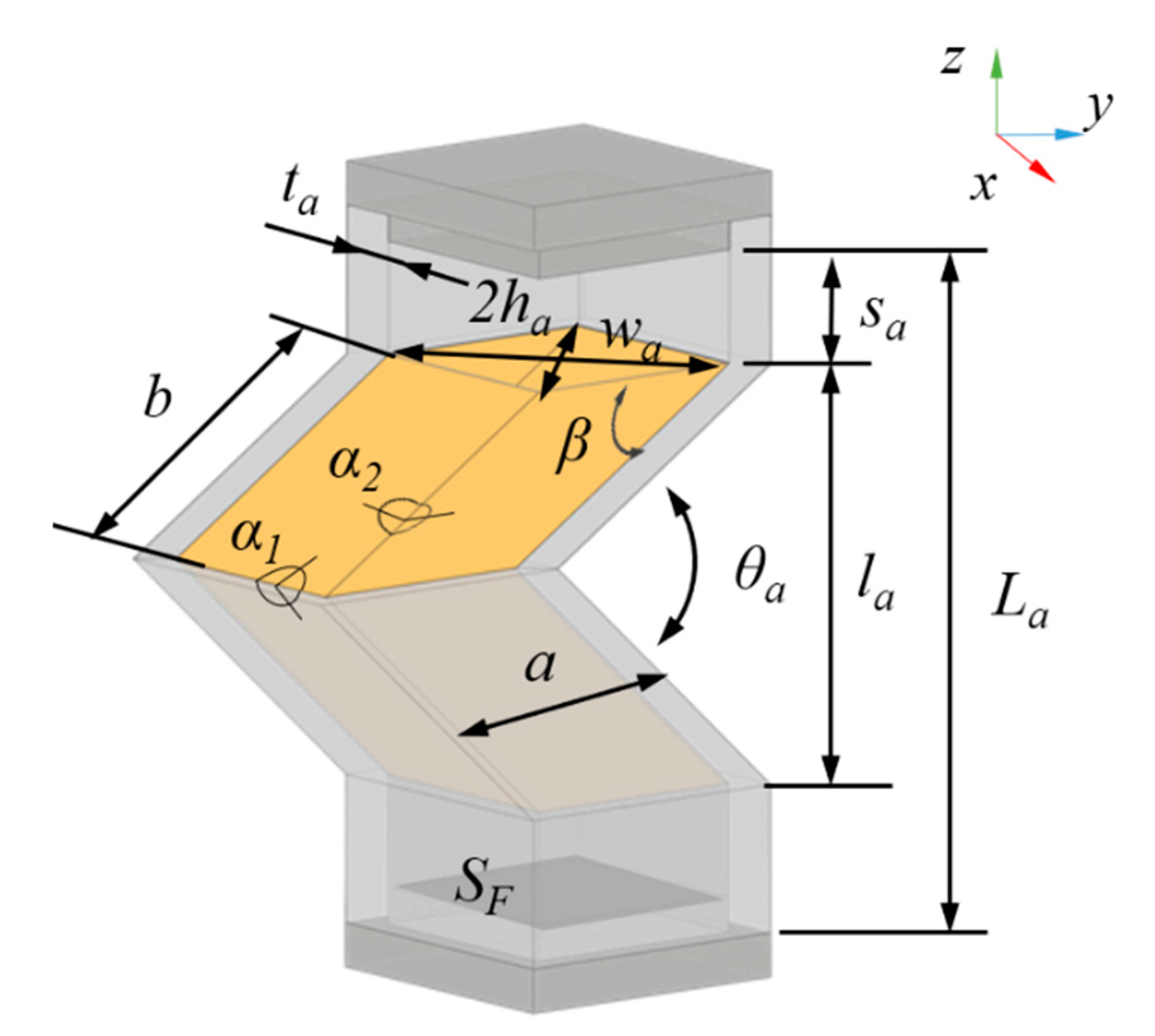
As shown in Figure 3, the parameters of the PFA are La, la, ta, sa, α1a, α2a, θa when PA = 0 kPa, and the parameters of deformable the PFA are Lb, lb, tb, sb, α1b, α2b, θb when the PA ≠ 0 kPa.
To simplify these calculations, some assumptions have been used. Firstly, through the deformation process of the PFA, the stiffness of the PFA is constant, and the parallelogram faces of the paper skeleton are unchanged. Further, the deformation of the PFA along the z-direction is only caused by the unfolding of the fold part and sa = sb, ta = tb; the cavity volume of the transition part is unchanged. Finally, the work done by the air is completely converted into the deformation of the foldable part.
Using these assumptions, the external work, W is a function of applied force F and displacement Δ L from the initial state of the foldable part of the PFA [31]:
W = F Δ L
In the deformation process, the work done by the foldable part of the PFA, W F , is:
Δ L = Δ L F = L b L a = l b l a F A = S F P A = P A w a h a W F = P A w a h a ( l b l a )
where Δ L is the length change of the PFA; Δ L F is the length change of the foldable part of the PFA; F A , the force of the PFA under PA.
The cavity volume of the foldable part of the PFA, V F can be calculated as:
V F = w b h b l b w a h a l a
From the conservation of energy, the work done by the PA converted into the work done by the foldable part of the PFA can be written as:
P A d V F = d W F
According to Equation (2), Equation (4), and Equation (6), PA and l b can be calculated using the following equation:
P A =   d W F d V F = f ( l b ) l b = f 1 ( P A )
Therefore, the length change of the PFA is the relation between the pressure of the PFA and the corresponding deformation, written as:
Δ L = Δ L F = l b l a = f 1 ( P A ) l a

2.3. Design of the Crawling Robot Composed of the Two PFAs

Using the mentioned features of the PFA, we designed a crawling robot that consists of the two PFAs based on Miura-ori, which can perform both linear and turning movements, according to the parallel structure and different control patterns.
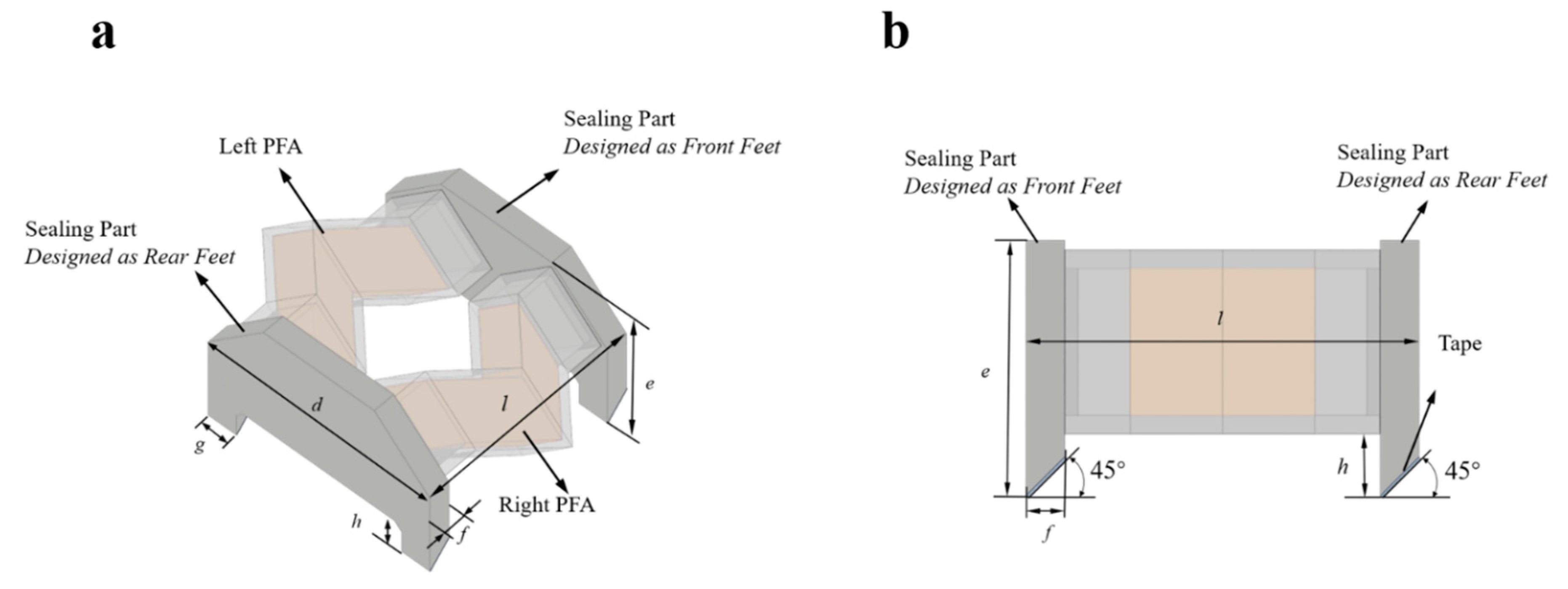
The crawling soft robot is composed of two independent PFAs, the left PFA and right PFA (Figure 4a). The right PFA and left PFA are controlled by two independent air supplies. The sealing parts of the right and left PFAs are designed as front feet and rear feet (Figure 4b). Due to the functional structures of the front and rear feet, the friction forces of the front feet and rear feet are different in the folding process and unfolding process of the PFAs. The parameters are shown in Table 2.

2.4. The Movement Patterns

By controlling the air pressure changes of the two independent PFAs, the crawling soft robot can not only move forward but also turn left and right. The different movement patterns depend on the different folding sequences. Because of the functional structure of the front and rear feet, in the process of the folding state and unfolding state, the state between the friction force of the front feet and rear feet is different. The atmospheric pressure is PO, the left PFA pressure is PL, and the right PFA pressure is PR. The required negative pressure is PN. The required positive pressure is PP.
The linear movement pattern: The crawling soft robot can move forward when the two actuators fold simultaneously. Figure 5 is the schematic diagram of the linear movement pattern in an ideal situation. There are five modes in a linear movement cycle. State A shows the original position of the crawling robot, PR = PL = PO. State B shows the folding process of the left and right PFA; the friction force of the front feet is larger than that of the rear feet, and the rear feet move forward with the folding of the PFA until PR = PL =PN < PO. State D is the unfolding process of the left and right PFA; the friction force of the rear feet is larger than that of the front feet, and the rear feet move forward with the unfolding of the PFA until pressure PR = PL ≤ PO ≤ PP. State E shows the final position of the crawling robot, PR = PL = PO. The forward moving distance is X in one linear movement cycle.
The turning movement pattern. The crawling robot makes a turning movement because of the different elongation of the two actuators. To make the most efficient turning movement, one actuator is in the folded state, the other switches its state between folded and unfolded during the turning movement process. There are five modes in a turning movement cycle. Figure 6 is the schematic diagram of the left-turning movement pattern in an ideal situation. State A and State B are the folding processes of the left and right PFAs, state C is the unfolding process of the right PFA; the friction force of the rear feet is larger than that of the front feet on the right side of the crawling robot. While PN= PL < PR = PP, the front feet deflect toward the lower frictional side and make a right turning movement. State D is the folding process of the right PFA; the friction force of the front feet is larger than that of the rear feet on the right side of the crawling robot. While PN = PL = PR, the rear feet deflect toward the lower frictional side and make a left turning movement. From state B to state E, the crawling robot makes a turning angle of γ. In general, if there is a pressure difference between PL and PR, the crawling robot can turn right either. The angle of turning is related to the magnitude of the pressure difference.

3. Materials and Fabrication

The foldable part, the transition part, and the sealing part are fabricated using the molds and casting approach. The molds were made of photosensitive resin using a three-dimensional printer (CoLiDo DLP 1.0, PRINT-RITE; Zhuhai, China) with a resolution of 0.05 mm. The foldable part and transition part were cast in a set of molds, and the thickness of the foldable part and transition part were 1 mm; the gap between the molds was small; as a result, we chose silicone with good elasticity and fluidity (Ecoflex 00-30, Smooth-On; Pennsylvania, America) to build the foldable part and the transition part. The Miura-ori pattern was printed on the printer paper (A4, 80g, Deli; Ningbo, China) and then cut along the edge of the Miura-ori unit with a knife and folded before being glued to the inner surface of the foldable part by soft glue (Silica Gel Soft Glue, Valigoo; Dongguan, China). We used silicone with a high elastic modulus (Dragon Skin 30, Smooth-On; Pennsylvania, America) to build the sealing part. Since the material of the sealing part had a much higher elastic modulus comparing with foldable part and transition part, the sealing part basically held still when the foldable part folded and the transition part deformed. Finally, we used Dragon Skin 10 NV to glue these parts together, and the tape was attached to the feet. The fabrication processes of the PFA and the crawling robot are shown in Figure 7.

4. Experiments and Results

4.1. The Pressure–Displacement and Volume–Pressure Curves

The PFA is designed to switch between negative and positive to perform a fold-inflation cycle. Based on observation from the previous test, we chose a working pressure from −10 kPa to 10 kPa for the PFA with a paper skeleton.
The experimental setup for measuring pressure–displacement is shown in Figure 8a. The pressure and displacement during the three steps were recorded by a pressure sensor (DP-101A, Panasonic; Suzhou, China) and displacement sensor (HG-C1050, Panasonic; Suzhou, China). The data from the pressure sensor and displacement were processed by RaspberryPi. The push or pull of the syringe is controlled by a stepper motor. The pressure of the PFA is controlled by the movement of the syringe according to the reading pressure value.
During the folding process, the sealing part at the top of the PFA will produce a different angle of inclination; in order to ensure the validity of the data, we specified that the data measured by the laser sensor were valid while the laser was irradiated in a circle with a radius of 2 mm on the top sealing part.
We defined a parameter η as the strain, η = Δ L /La, where Δ L is the length change of the PFA under pressure PA ≠ 0 compared with the original length, and La (theoretical length = 24.14 mm, actual length = 23.70 mm) is the original length while PA = 0. The measurement consists of three steps: (1) folding, the PFA contracts from the initial state to the folded state by syringe extraction from the PFA until PA =−10 kPa; (2) unfolding, the PFA is unfolded from the folded state by syringe injection into the PFA until PA = 10 kPa; (3) recovery, the PFA recovers to the initial state until PA = 0 kPa. The curves are as shown in Figure 8b,c, and the state of the PFA under different pressure is shown in Figure 8d.
From the pressure-displacement and volume-pressure curves, the following was observed: (1) in the process of folding and unfolding, the slope decreases dramatically from 0~−5 kPa, and the slope changes slowly from −5 kPa~−10 kPa; the slope under the positive pressure and the slope from 0~−5 kPa are approximately linear; (2) The maximum strain ηmax = 0.43 under negative pressure, PA= −10 kPa, and the maximum strain ηmax = 0.19 under positive pressure, PA = 10 kPa; the PFA varies more under negative pressure than under positive pressure; (3) when the air volume of the PFA is reduced or increased by about 6 mL, the pressure changes are approximately equal; (4) in the process of folding and unfolding, the slope changes slowly from −4 ml~6 ml, but the slope decreases dramatically from −4ml~−6ml, the slope from 0~6 ml is approximately linear.
We made a comparison between the PFA with or without the paper skeleton and chose the working pressure from −10 kPa to 6 kPa for the PFA without a paper skeleton (Figure 8e). By comparing Figure 8d with Figure 8e, it is observed that the paper skeleton had a good limiting effect in the axial direction, which makes the PFA have a more stable deformation along the z-direction.
The soft actuators are usually designed to perform like muscle, and the PFA can also generate larger force under negative pressure. In order to acquire the behavior of the PFA versus load, the sealing part was designed with a hole for hanging weights. The weight of the PFA is 2.52 g, and the magnitude of the load is 10 g. The behavior of the PFA versus the load is as shown in Figure 8f. The PFA can lift an object four times heavier than itself.

4.2. Determining the Working Pressure for the Crawling Robot

Through experimentation, a vacuum degree of 10 kPa is sufficient to achieve the action of the robot. However, the folding process can be accelerated using a lower pressure. The positive pressure of 5 kPa was chosen, and unfolding process can be slowed using a lower pressure in order to improve the crawling efficiency and reduce the asymmetric inflation of the two PFAs for manufacturing errors. In the later experiments, we used a vacuum degree of 20 kPa and positive pressure of 5 kPa to drive the crawling robot.

4.3. The Movement of the Crawling Robot

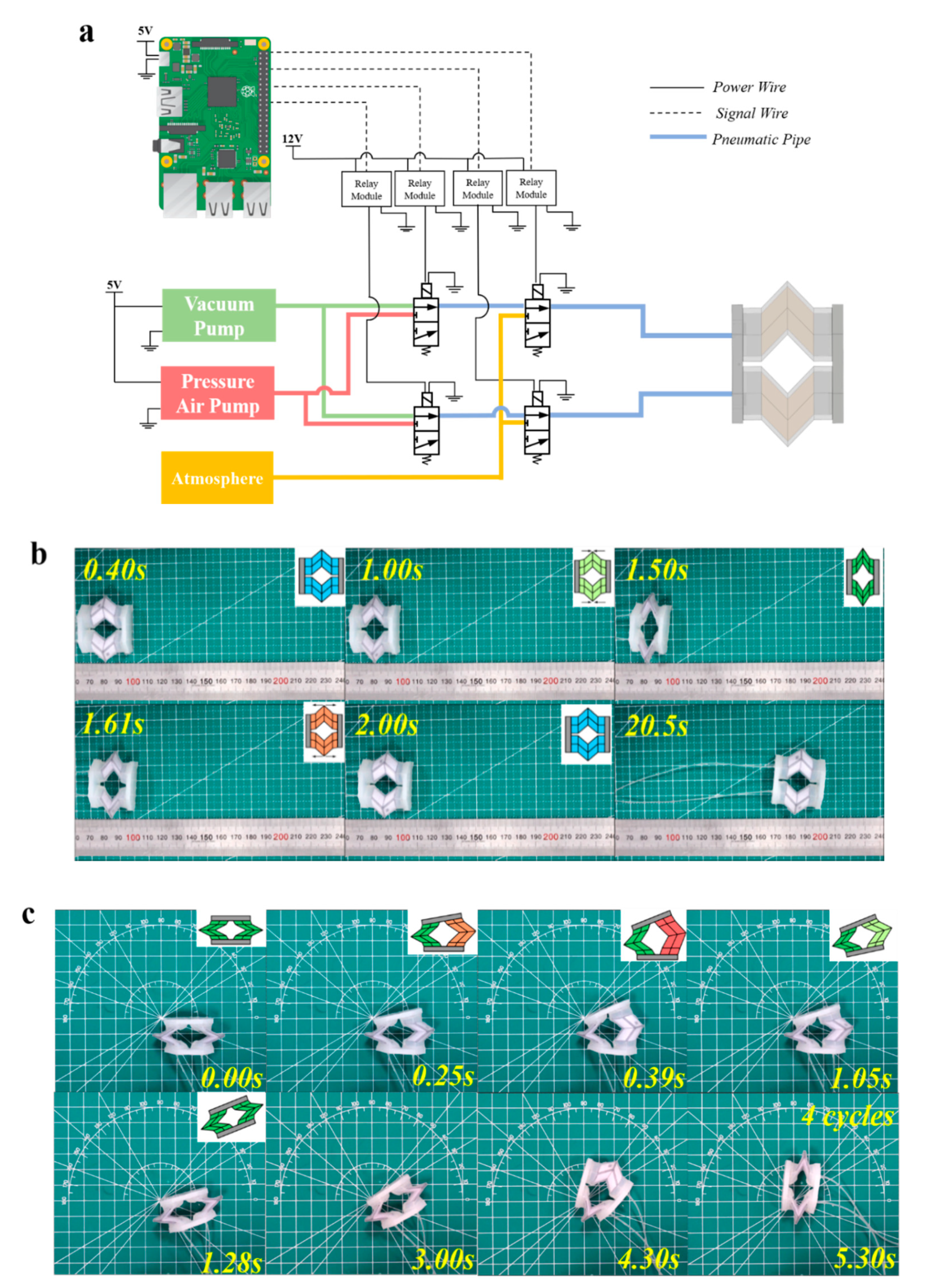
The experimental setup for controlling the crawling robot is as shown in Figure 9a, mainly containing a pressure air pump, vacuum pump, three-way solenoid valve, and relay module. The right and left PFAs are connected to two independent air supplies which can switch between a vacuum pump and air pump.
The linear movement. The crawling robot crawls along one direction on a plane as shown in Figure 9b. The crawling gait is based on the folding and unfolding state of the PFAs. By periodically switching the solenoid valve, the right and left PFAs fold or unfold simultaneously. In the test, the crawling robot in a forward motion had a velocity of about 5 mm/s.
The turning movement. The crawling robot turning left on a plane is shown in Figure 9c. The crawling gait is based on the different folding and unfolding state between the left and right PFAs. By periodically switching the solenoid valve, the right and left PFAs are folded or unfolded differentially. In the test, the crawling robot turned with an angular velocity of about 15°/s.
Compared with the existing soft crawling robots based on soft pneumatic actuators [6,13,14,16], the crawling robot driven by the PFAs is superior in terms of locomotion speed and efficiency. As shown in Table 3, the crawling robot driven by the PFAs had a turning speed of about 15°/s with a shorter body length, which is one of the fastest among the existing soft crawling robots based on the research by us and other scholars [13].

5. Conclusions and Future Work

Here, we designed a crawling robot consisting of two foldable pneumatic actuators, front and rear feet. It can perform both linear and turning movements, according to the different control patterns (Supplementary Movie S1 and S2). The working pressure is determined by experiments to confirm the properties of the foldable pneumatic actuator.
Compared with most of the soft crawling robots, the linear and turning movements of the crawling robot based on the Miura-ori structure mainly depend on the length change by the folding of the actuator under a low negative pressure, instead of elongating or bending the actuators under positive pressure. The height of the crawling robot does not change during the movement. Therefore, the crawling robot based on the Miura-ori structure is more suitable for movement in height-limited space. The crawling robot with a micro-camera can move in low ventilation ducts to detect faults or can move in the gaps of collapsed ruins to help staff search and rescue.
The design presented here has the following limitations: (1) the silicone cannot be folded like paper, and the structure needs to be improved; (2) the crawling robot lacks feedback control and information exchange, so it cannot be regulated in time, and large deflections may arise during long-distance motion. In future work, a micro-camera and three-axis electronic compass sensor can be embedded in the front and rear of the robot, and then we can adjust the posture and position of the robot based on the information from the sensors. A combination of a robot with machine vision and machine learning and training will make the robot smarter, which is also the direction of our next efforts.

Supplementary Materials

The following are available online at https://www.mdpi.com/2076-0825/9/2/26/s1, Movie S1: The linear movement of the crawling robot; Movie S2: The turning movement of the crawling robot.

Author Contributions

Conceptualization, M.Y.,W.Y. and Z.J.; methodology, M.Y. and X.C.; software, M.Y.; validation, M.Y., Y.Y. and Z.J.; investigation, Z.J.; resources, W.Y.; data curation, W.Y., Y.Y., and Z.J.; writing—original draft preparation, M.Y.; writing—review and editing, Y.Y., Z.W. and X.C.; supervision, W.Y.; project administration, X.C. and Z.J. All authors have read and agreed to the published version of the manuscript.

Funding

This research was funded by Zhuhai Industrial Core and Key Technology Research Project (ZH01084702180085HJL). National Natural Science Foundation of China (No.51905530), and China Postdoctoral Science Foundation (No.2018M641440).

Conflicts of Interest

No competing financial interests exist.

References

  1. Rus, D.; Tolley, M.T. Design, fabrication and control of soft robots. Nature 2015, 521, 467–475. [Google Scholar] [CrossRef] [PubMed] [Green Version]
  2. Shepherd, R.F.; Ilievski, F.; Choi, W.; Morin, S.A.; Stokes, A.A.; Mazzeo, A.D.; Chen, X.; Wang, M.; Whitesides, G.M. Multigait soft robot. Proc. Natl. Acad. Sci. USA 2011, 108, 20400–20403. [Google Scholar] [CrossRef] [Green Version]
  3. Hawkes, E.W.; Blumenschein, L.H.; Greer, J.D.; Okamura, A.M. A soft robot that navigates its environment through growth. Sci. Robot. 2017, 2, 1–8. [Google Scholar] [CrossRef] [Green Version]
  4. Ge, J.Z.; Calderón, A.A.; Chang, L.; Pérez-Arancibia, N.O. An earthworm-inspired friction-controlled soft robot capable of bidirectional locomotion. Bioinspir. Biomim. 2019, 14, 036004. [Google Scholar] [CrossRef] [PubMed]
  5. Chatterjee, S.; Niiyama, R.; Kawahara, Y. Design and Development of a Soft Robotic Earthworm with Hydrostatic Skeleton. In Proceedings of the 2017 IEEE International Conference on Robotics and Biomimetics (ROBIO), Macau, China, 5–8 December 2017; pp. 1–6. [Google Scholar]
  6. Zou, J.; Lin, Y.; Ji, C.; Yang, H. A Reconfigurable Omnidirectional Soft Robot Based on Caterpillar Locomotion. Soft Robot. 2018, 5, 164–174. [Google Scholar] [CrossRef] [PubMed]
  7. Rafsanjani, A.; Zhang, Y.; Liu, B.; Rubinstein, S.M.; Bertoldi, K. Kirigami skins make a simple soft actuator crawl. Sci. Robot. 2018, 3, eaar7555. [Google Scholar] [CrossRef] [Green Version]
  8. Luo, M.; Agheli, M.; Onal, C.D. Theoretical Modeling and Experimental Analysis of a Pressure-Operated Soft Robotic Snake. Soft Robot. 2014, 1, 136–146. [Google Scholar] [CrossRef]
  9. Fras, J.; Noh, Y.; Macias, M.; Wurdemann, H.; Althoefer, K. Bio-Inspired Octopus Robot Based on Novel Soft Fluidic Actuator. In Proceedings of the 2018 IEEE International Conference on Robotics and Automation (ICRA), Paris, France, 31 May–4 June 2018; pp. 1583–1588. [Google Scholar]
  10. Laschi, C.; Cianchetti, M.; Mazzolai, B.; Margheri, L.; Follador, M.; Dario, P. Soft Robot Arm Inspired by the Octopus. Adv. Robot. 2012, 26, 709–727. [Google Scholar] [CrossRef]
  11. Cianchetti, M.; Calisti, M.; Margheri, L.; Kuba, M.; Laschi, C. Bioinspired locomotion and grasping in water: The soft eight-arm OCTOPUS robot. Bioinspir. Biomim. 2015, 10, 035003. [Google Scholar] [CrossRef]
  12. Li, T.; Zou, Z.; Mao, G.; Yang, X.; Liang, Y.; Li, C.; Qu, S.; Suo, Z.; Yang, W. Agile and Resilient Insect-Scale Robot. Soft Robot. 2019, 6, 133–141. [Google Scholar] [CrossRef]
  13. Qin, L.; Liang, X.; Huang, H.; Chui, C.K.; Yeow, R.C.H.; Zhu, J. A Versatile Soft Crawling Robot with Rapid Locomotion. Soft Robot. 2019, 6, 455–467. [Google Scholar] [CrossRef] [PubMed]
  14. Wu, P.; Jiangbei, W.; Yanqiong, F. The Structure, Design, and Closed-Loop Motion Control of a Differential Drive Soft Robot. Soft Robot. 2018, 5, 71–80. [Google Scholar] [CrossRef] [PubMed]
  15. Cao, J.; Qin, L.; Liu, J.; Ren, Q.; Foo, C.C.; Wang, H.; Lee, H.P.; Zhu, J. Untethered soft robot capable of stable locomotion using soft electrostatic actuators. Extrem. Mech. Lett. 2018, 21, 9–16. [Google Scholar] [CrossRef]
  16. Tolley, M.T.; Shepherd, R.F.; Mosadegh, B.; Galloway, K.C.; Wehner, M.; Karpelson, M.; Wood, R.J.; Whitesides, G.M. A Resilient, Untethered Soft Robot. Soft Robot. 2014, 1, 213–223. [Google Scholar] [CrossRef]
  17. Li, T.; Li, G.; Liang, Y.; Cheng, T.; Dai, J.; Yang, X.; Liu, B.; Zeng, Z.; Huang, Z.; Luo, Y.; et al. Fast-moving soft electronic fish. Sci. Adv. 2017, 3, e1602045. [Google Scholar] [CrossRef] [Green Version]
  18. Bartlett, N.W.; Tolley, M.T.; Overvelde, J.T.B.; Weaver, J.C.; Mosadegh, B.; Bertoldi, K.; Whitesides, G.M.; Wood, R.J. A 3D-printed, functionally graded soft robot powered by combustion. Science 2015, 349, 161–165. [Google Scholar] [CrossRef] [Green Version]
  19. Tang, Y.; Zhang, Q.; Lin, G.; Yin, J. Switchable Adhesion Actuator for Amphibious Climbing Soft Robot. Soft Robot. 2018, 5, 592–600. [Google Scholar] [CrossRef]
  20. Rus, D.; Tolley, M.T. Design, fabrication and control of origami robots. Nat. Rev. Mater. 2018, 3, 101–112. [Google Scholar] [CrossRef]
  21. Pagano, A.; Yan, T.; Chien, B.; Wissa, A.; Tawfick, S. A crawling robot driven by multi-stable origami. Smart Mater. Struct. 2017, 26, 094007. [Google Scholar] [CrossRef]
  22. Jeong, D.; Lee, K. Design and analysis of an origami-based three-finger manipulator. Robotica 2018, 36, 261–274. [Google Scholar] [CrossRef] [Green Version]
  23. Fang, H.; Zhang, Y.; Wang, K.W. Origami-based earthworm-like locomotion robots. Bioinspir. Biomim. 2017, 12, 065003. [Google Scholar] [CrossRef] [PubMed]
  24. Lee, D.-Y.; Kim, S.-R.; Kim, J.-S.; Park, J.-J.; Cho, K.-J. Origami Wheel Transformer: A Variable-Diameter Wheel Drive Robot Using an Origami Structure. Soft Robot. 2017, 4, 163–180. [Google Scholar] [CrossRef] [PubMed]
  25. Martinez, R.V.; Fish, C.R.; Chen, X.; Whitesides, G.M. Elastomeric origami: Programmable paper-elastomer composites as pneumatic actuators. Adv. Funct. Mater. 2012, 22, 1376–1384. [Google Scholar] [CrossRef]
  26. Miura, K. Method of Packaging and Deployment of Large Membranes in Space. Inst. Sp. Astronaut. Sci. Rep. 1985, 618, 1–9. [Google Scholar]
  27. Schenk, M.; Guest, S.D. Geometry of Miura-folded metamaterials. Proc. Natl. Acad. Sci. USA 2013, 110, 3276–3281. [Google Scholar] [CrossRef] [Green Version]
  28. Nishiyama, Y. Miura folding: Applying origami to space exploration. Int. J. Pure Appl. Math. 2012, 79, 269–279. [Google Scholar]
  29. Zhou, X.; Zang, S.; You, Z. Origami mechanical metamaterials based on the Miura-derivative fold patterns. Proc. R. Soc. A Math. Phys. Eng. Sci. 2016, 472, 20160361. [Google Scholar] [CrossRef]
  30. Lv, C.; Krishnaraju, D.; Konjevod, G.; Yu, H.; Jiang, H. Origami based Mechanical Metamaterials. Sci. Rep. 2015, 4, 5979. [Google Scholar] [CrossRef] [Green Version]
  31. Grey, S.W.; Schenk, M.; Scarpa, F.L. Local Actuation of Tubular Origami. In Proceedings of the seventh meeting of Origami, Science, Mathematics and Education, Oxford, UK, 4–7 September 2018. [Google Scholar]
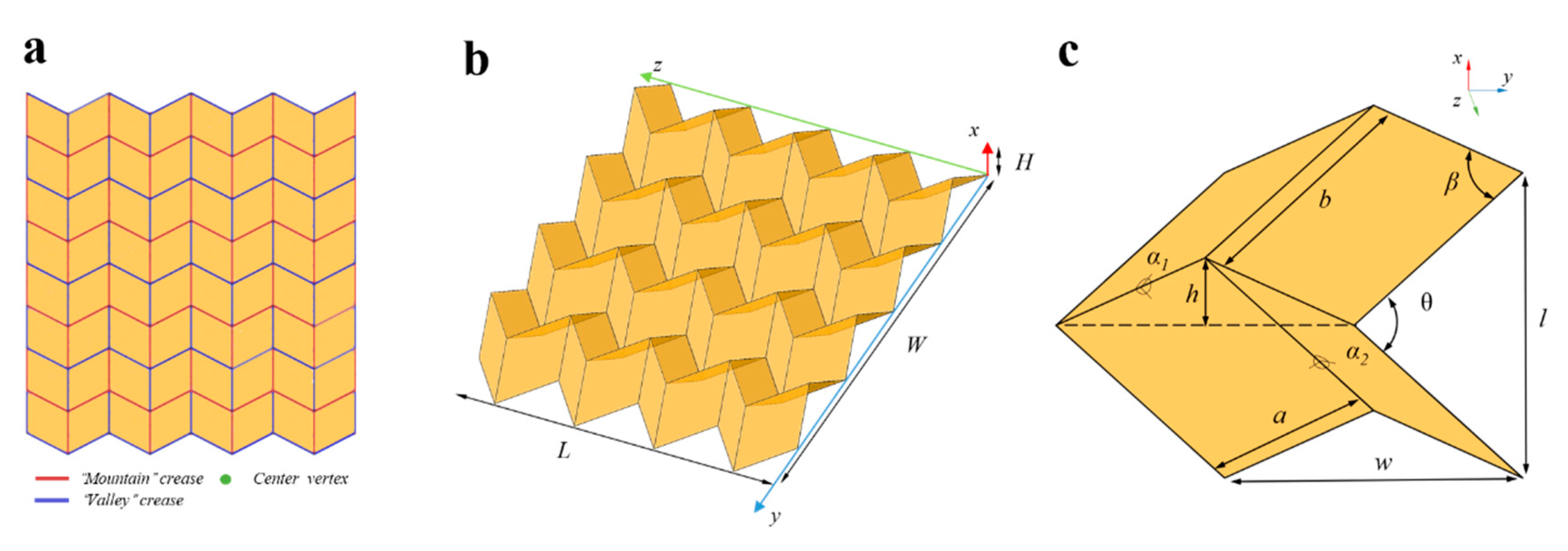
Figure 1. Illustration of Miura-ori. (a) A Miura-ori in its planner state; red lines represent ‘‘mountain’’ creases, the blue lines represent ‘‘valley’’ creases. (b) Miura-ori in its folded state; the red lines are on the top, and the blue lines are on the bottom, four vertices in the z direction, four vertices in the y direction. (c) A unit cell of Miura-ori; α1 and α2 are two dihedral angles. In each parallelogram, the length of the short side is a and that of the long side is b, with an acute angle of β. The projected angle between the two ridges is θ. The size of the unit cell is H, W, and L in the x, y, and z directions.
Actuators 09 00026 g001
Figure 2. The Pneumatic foldable actuator(PFA). (a) The PFA is composed of a sealing part, transition part, and folding part; (b) In the folding process of the foldable part, the cross-section of the foldable part parallel to the y-z plane will change from a square to a parallelogram; (c) Deformation of the PFA under different states: the initial state of the PFA (PA = 0); the folding state, the PFA reduces its length under negative pressure (PA < 0); the inflation state, the PFA extends its length under positive pressure (PA > 0).
Actuators 09 00026 g002
Figure 3. The parameters of the PFA when the PA = 0 kPa; the parameters of the PFA are La, la, ta, sa, α1a, α2a, θa, and the parameters of the deformable PFA are Lb, lb, tb, sb, α1b, α2b, θb when the PA ≠ 0 kPa.
Actuators 09 00026 g003
Figure 4. (a) The crawling soft robot is composed of the two independent PFAs, the left PFA and right PFA. (b) The sealing part is designed as feet from the left view.
Actuators 09 00026 g004
Figure 5. The schematic diagram of the linear movement pattern from the top view. (A) The original state; (B) The folding process of the left and right PFAs; (C) The folded state; (D) The unfolding process of the left and right PFAs; (E) The unfolded state.
Actuators 09 00026 g005
Figure 6. The schematic diagram of the left-turning movement pattern from the top view. (A) The folded state of the left and right PFA; (B) The unfolding process of the right PFA; (C) The unfolded state of the right PFA; (D) The folding process of the right PFA; (E) The folded state of the right PFA.
Actuators 09 00026 g006
Figure 7. The fabrication processes of the PFA and the crawling robot.
Actuators 09 00026 g007
Figure 8. (a) The experimental setup for measuring; (b) The pressure–displacement curve; (c) The volume–pressure curve; (d) The PFA with a paper skeleton under different pressure from −10 kPa to 10 kPa; (e) The PFA without a paper skeleton under different pressure from −10 kPa to 6 kPa; (f) The PFA designed as a pneumatic muscle; (g) The behavior of the PFA versus load.
Actuators 09 00026 g008
Figure 9. (a) The experimental setup for controlling the crawling robot; (b) The linear movement of the crawling robot; (c) The turning movement of the crawling robot.
Actuators 09 00026 g009
Table 1. The Parameters of the Pneumatic Foldable Actuator.
ParametersValue
a10 mm
b10 mm
β60°
α290°
θ90°
w7.07 mm
l14.14 mm
Table 2. The Parameters of the Crawling robot.
ParametersValue
The length of the crawling robot l (mm)32
The width of the crawling robot d (mm)31
The height of the crawling robot e (mm)20
The thickness of the front and rear feet f (mm)3
The width of the front and rear feet g (mm)4
The height of the front and rear feet h (mm)4
Table 3. A Comparison of Different Soft Crawling Robots.
Soft Crawling RobotActuation MethodBody Length
(mm)
Turning Speed
(°/s)
Linear Speed
(mm/s)
LS/BL
Our robotPneumatic32~15~5~0.15
Zou et al. [6]Pneumatic154~1.63~5~0.032
Qin et al. [13]Pneumatic13515.09160.11
Wu et al. [14]Pneumatic~110~1.239.850.089
Tolley et al. [16]Pneumatic650~0.2~5~0.007
LS, Linear speed; BL, Body Length.