Article

Optimal Magnetic Spring for Compliant Actuation—Validated Torque Density Benchmark †

1
Department of Mechanical Engineering, Katholieke Universiteit Leuven, 3001 Leuven, Belgium
2
MotionS core lab, Flanders Make, 3001 Leuven, Belgium
3
DMMS core lab, Flanders Make, 3001 Leuven, Belgium
*
Author to whom correspondence should be addressed.
This paper is an expanded version on: Mrak, B.; Lenaerts, B.; Driesen, W.; Desmet, W. Optimal Design of Magnetic Springs; Enabling High Life Cycle Elastic Actuators. In proceedings of the 16th International Symposium on Magnetic Bearings (ISMB16), Beijing, China, 13–17 August 2018.
Actuators 2019, 8(1), 18; https://doi.org/10.3390/act8010018
Submission received: 18 January 2019 / Revised: 14 February 2019 / Accepted: 18 February 2019 / Published: 22 February 2019

Abstract

:
Magnetic springs are a fatigue-free alternative to mechanical springs that could enable compliant actuation concepts in highly dynamic industrial applications. The goals of this article are: (1) to develop and validate a methodology for the optimal design of a magnetic spring and (2) to benchmark the magnetic springs at the component level against conventional solutions, namely, mechanical springs and highly dynamic servo motors. We present an extensive exploration of the magnetic spring design space both with respect to topology and geometry sizing, using a 2D finite element magnetostatics software combined with a multi-objective genetic algorithm, as a part of a MagOpt design environment. The resulting Pareto-optima are used for benchmarking rotational magnetic springs back-to-back with classical industrial solutions. The design methodology has been extensively validated using a combination of one physical prototype and multiple virtual designs. The findings show that magnetic springs possess an energy density 50% higher than that of state-of-the-art reported mechanical springs for the gigacycle regime and accordingly a torque density significantly higher than that of state-of-the-practice permanently magnetic synchronous motors.

1. Introduction

The principles of elastic actuation, first introduced by Alexander et al. [1], whether in series [2] or in parallel [3] elastic actuators have been consistently proven to improve actuator performance in service robotics. These systems rely on the high torque and force density of mechanical springs to reduce peak power requirements and to improve the actuator’s energy efficiency. For example, in work done by Mettin et al. [4], the energy consumption is reduced by 55%. The goal of this paper is to offer a robust spring solution, in the form of magnetic springs, that can extend the use of elastic actuation from service robotics to widespread industrial robots but also a much broader family of highly dynamic industrial motion systems.
A mechanical spring stores energy as the potential energy of elastic deformation. Spring design for highly dynamic loads in industrial use is typically limited by the long lifetime requirements and often leads to suboptimal designs for the purposes of elastic actuation. Conventionally, it was considered that for some metals there is a stress level called the fatigue limit, that can be sustained with an infinite lifetime [5]. Nowadays, this value is still often used in the design together with the stochastic design methods. However, the existence of a fatigue limit has been disputed even in the lab environment due to inclusions in the crystal lattice [6] of steel. Local stresses can lead to fatigue in any kind of metallic springs [5,6,7,8] and industrial environments impose additional risks (i.e., corrosive environment, temperature variations, mechanical handling, manufacturing limitations etc.). Often, high safety factors are employed to guarantee a robust design for a full product line, leading to heavy springs with high inertia.
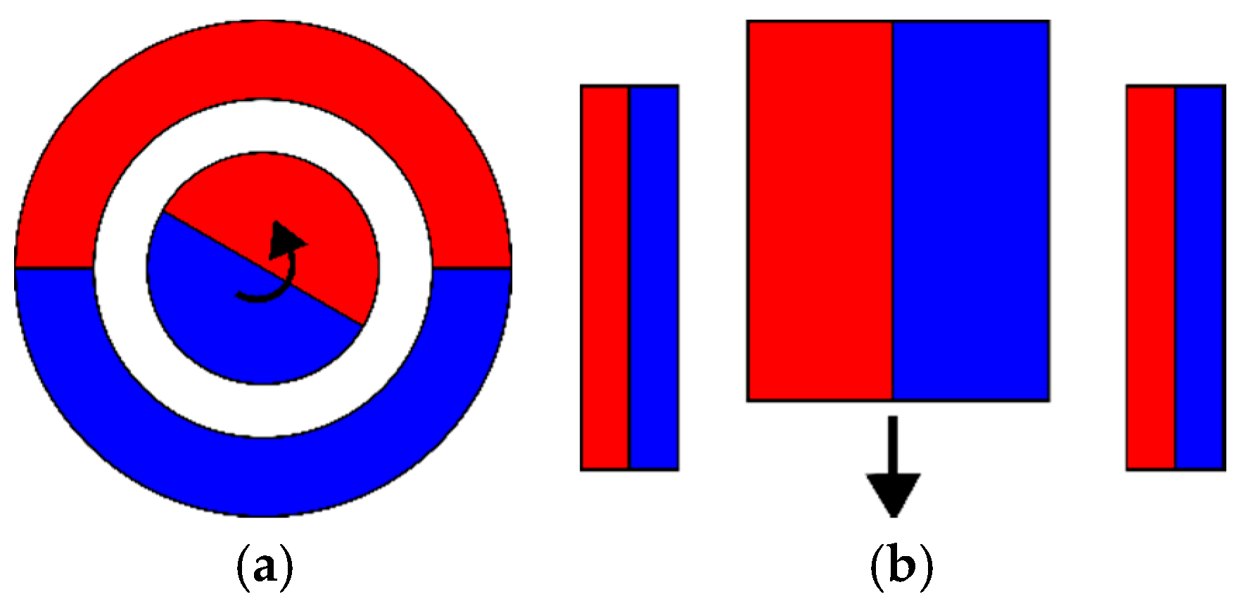
Although the functionality of the magnetic spring (Figure 1) can be compared to that of a mechanical spring, the underlying physical principles are utterly different. Magnetic springs store potential energy in the magnetic field of permanent magnets (PM), where no fatigue failure mechanism is involved and thus have a virtually infinite lifetime [9], assuming the device is properly designed. This allows the use of compliant actuation concepts [10] in highly dynamic industrial applications with stringent lifetime demands.
With elastic actuators, it is possible to deliver more mechanically reactive power to the system, under the assumption of a higher torque density of springs compared to motors. Considering the evident benefit of using mechanical springs in service robotics in improving dynamic behavior, it is necessary to prove that magnetic springs have the same or higher energy density than conventional solutions with mechanical springs, in order to showcase their potential for the design of industrial motion systems.
Some of the target applications are torque oscillation, compensation in continuous rotation in internal combustion engines and windmills, reciprocating and intermittent motion in weaving looms [11], fast switching valves [12] (valvetrains in internal combustion engines), reciprocating pumps and compressors [13] and other tools and machines with a highly dynamic reciprocating motion. Additionally, magnetic springs have been reported for use in vibration reduction and vibration isolation [14] as well as for static load compensation [15]. It is worth mentioning that magnetic springs are topologically identical to passive magnetic bearings (PMB) and magnetic clutches. The main difference is the magnetic load point of the permanent magnets: in a magnetic spring the magnets are loaded over the entire B-H curve in each loading cycle, while for PMB and clutches the operating point remains constant for a constant mechanical load.
Unlike the previous efforts on the topic, where effort was focused on a specific use, this paper studies the optimal design of a magnetic spring in more detail and demonstrates systematically the impact of a magnetic spring on the performance of highly dynamic industrial actuators. This article is based on conference paper [16] where the optimal component design methodology was presented. That methodology was extended with a more elaborate, reproducible validation campaign including dynamic validation data, and multiple virtual optimal design points in requirement space. Additionally, for the purposes of benchmarking, more stress was put on the experimental validation and virtual validation using models of differing complexity. For the same reason, the mechanical and magnetic spring, including temperature effects on both the magnetic and mechanical springs, is considered. The closed form magnetic spring scaling model with model limitations is presented, as opposed to the intuitive yet incomplete model in the conference paper, making the experimental validation fully reproducible. Finally, in the discussion section, there is a significant amount of new benchmarking data for torque density comparison of magnetic springs and permanent magnet synchronous motors (PMSM). In addition, the exact data points and the designs will be made available via a link or in the addendum.

2. Materials and Methods

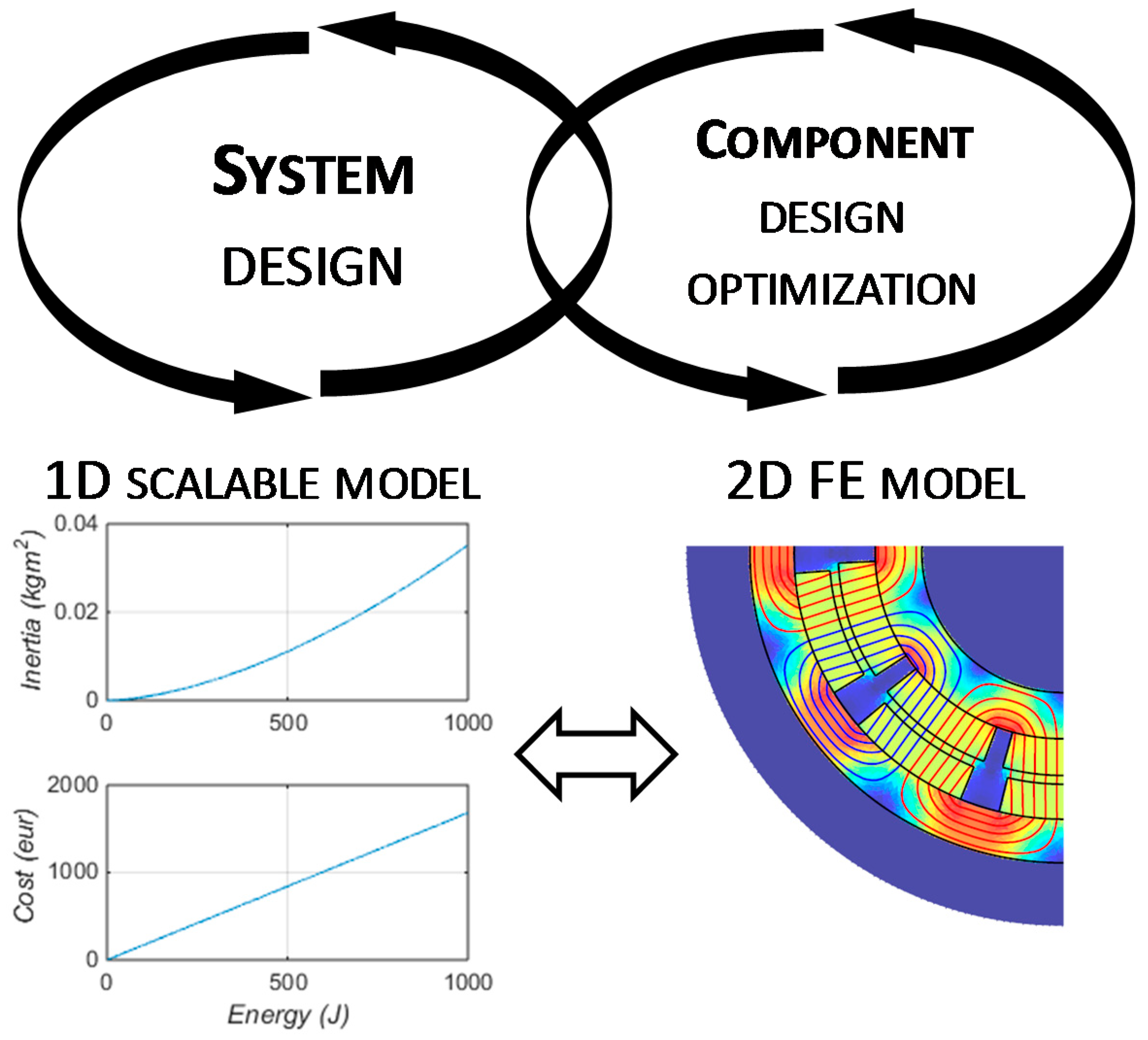
Within this article, the focus is primarily on the component design cycle but we will also present its complementarity with the system design cycle (Figure 2). The main subject of this study is rotational magnetic springs, although some of the considerations regarding energy density can also be translated to linear magnetic springs. Regarding the environment where the magnetic springs can be used, we consider that due to the limitations of permanent magnetic materials, environments where PMSM can operate are considered to be suitable for magnetic springs.
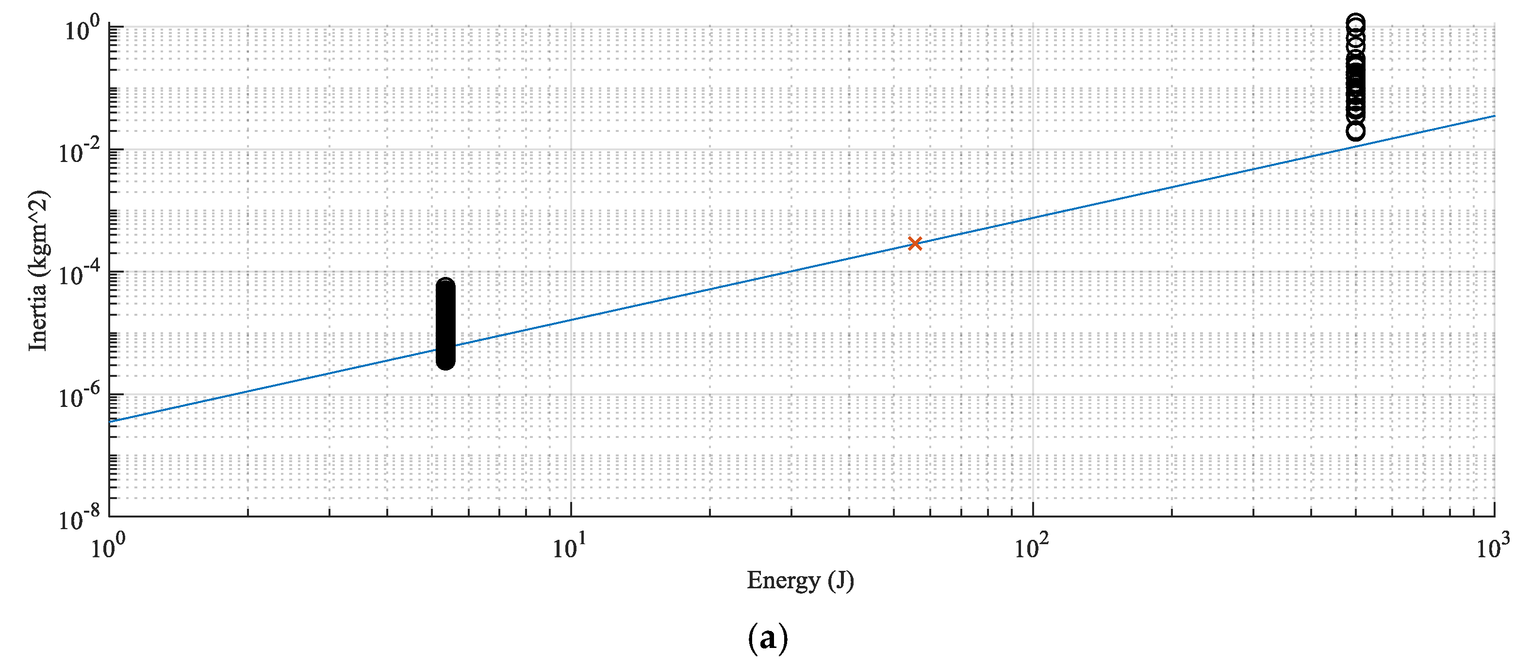
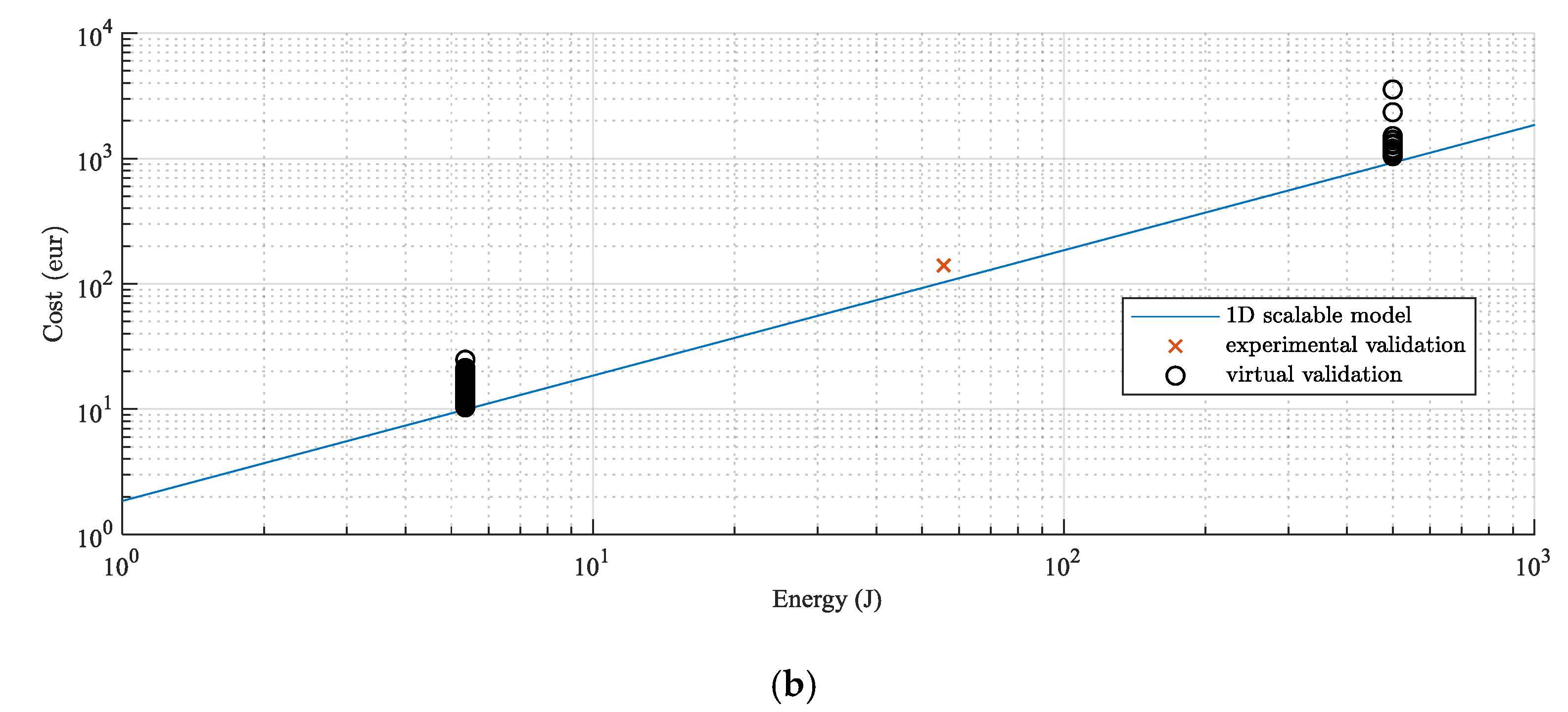
Although the FE model of a detailed design geometry is an indispensable tool for component design, in system optimization the computational cost of finite elements (FE) can be prohibitively expensive. On the other hand, a scalable 1D dynamic model of a magnetic spring is the ideal model for the sizing of different drivetrain components and system optimization. Therefore, we define a 1D scalable model based on first principles, where cost and inertia of a magnetic spring are calculated directly from required reactive energy. This model can be iteratively updated based on the FE model results, as a result of the virtual validation where a 1D model is compared to optimal component designs coming from component optimization design.
A standard way to compare energy-storing devices is a Ragone chart [17]. It typically shows the tradeoff between energy density and power density, i.e., some energy storage components should be used when a high energy density is required (e.g., Li-ion batteries) and others when high instantaneous power is required (supercapacitors, flywheels). The bottleneck of such a static approach when it comes to highly dynamic drivetrains is the disregard for lifetime and system dynamics. In the highly dynamic applications targeted within this study, the mechanical power delivered to the system is significantly limited by the torque density of the actuator i.e., the ratio of torque limitation and inertia of the said actuator.
Therefore, it is necessary to know the inertia of the spring alongside the torque characteristics. Phenomenologically we can analyze the energy density of a spring. For elastic springs this will be the surface under the stress-strain curve (for the linear elastic model where the relation of stress and strain is linearly described by Young’s modulus). Equivalently, for an idealized magnetic spring, the energy density is equivalent to the surface under the BH curve (Figure 3), which can be calculated as
E m a x = H c 0 B ( H ) d H 2 B H m a x
where B is the magnetic flux density and H is magnetic field strength.
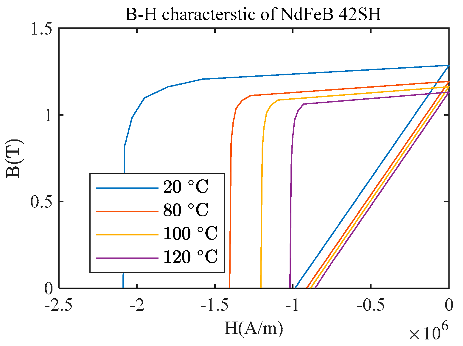
Two assumptions about the magnetic spring have to be made in order to create a 1D scalable model. First of all, equal distribution of magnets between stator and rotor, resulting in perfect canceling of the magnetic field in the magnets in the case where maximum potential energy is stored within the magnet. Secondly, a fixed form factor of the rotor, following the 1st assumption and optimal rotor diameter achieved from FE simulation. It is important to note that variation of a permanent magnetic energy density of 30.79% for a 100 °C difference can result in a significant stiffness variation with temperature, while mechanical springs will normally have less than 5% [18] for the same region. Keep in mind that the magnetic springs are not expected to generate significant heat, yet, for an expected environmental variation of ±20 °C, the magnetic spring will have a variation of ±5%. Although the SmCo material has a higher Curie temperature and can allow for a slightly higher operational temperature, this large stiffness variation and the possibility of demagnetization limits the magnetic spring from operating in a high-temperature environment where mechanical springs face less severe limitations.
Furthermore, realistic designs of a magnetic spring will always have a lower energy density than the maximum theoretical limit, due to effects like fringing and flux leakage. Therefore, we can define the design efficiency as an energy density ratio of a realistic magnetic spring and an ideal magnetic spring
η m a t = E F E E m a x
and use it for 1D model correction based on FE results.
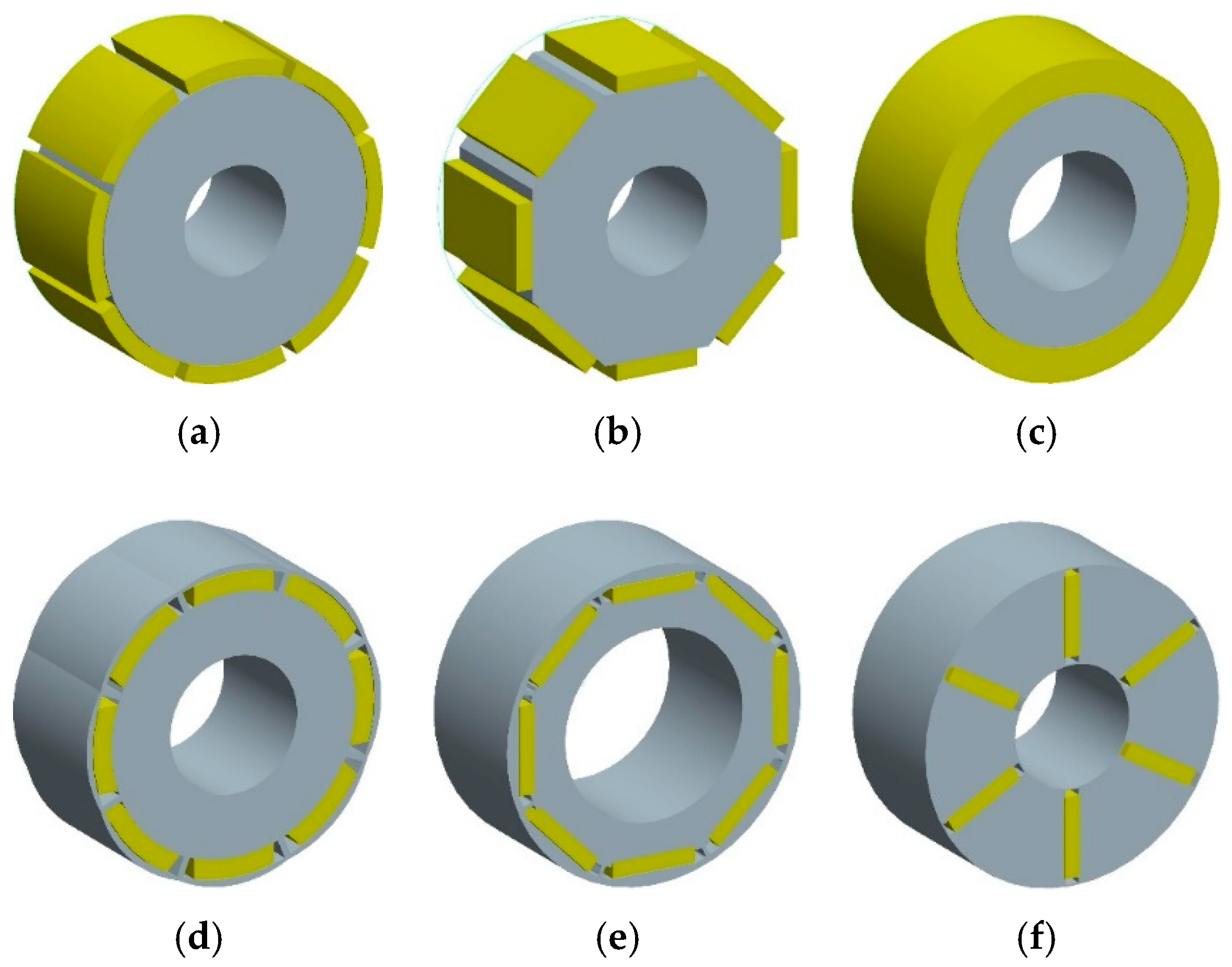
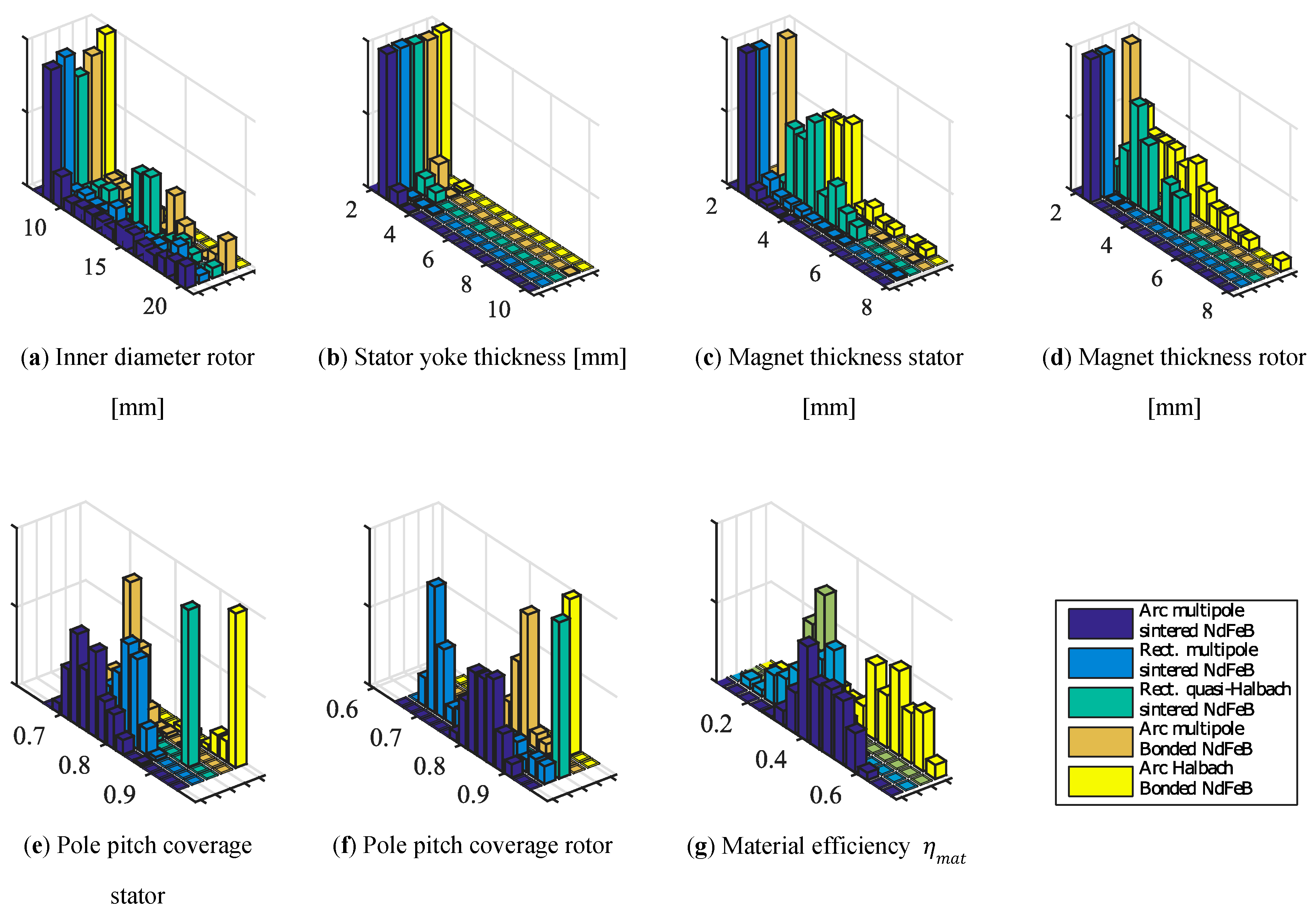
For the realistic embodiment of the magnetic spring concept, there is a range of feasible variants, both continuous (geometry sizing) and discrete (topological). By permutation of the discrete variants such as the PM materials in Table 1, or rotor and stator topologies shown in Figure 4, we can generate a number of topologies (Table 2), of which a number can be pruned out early in the design.
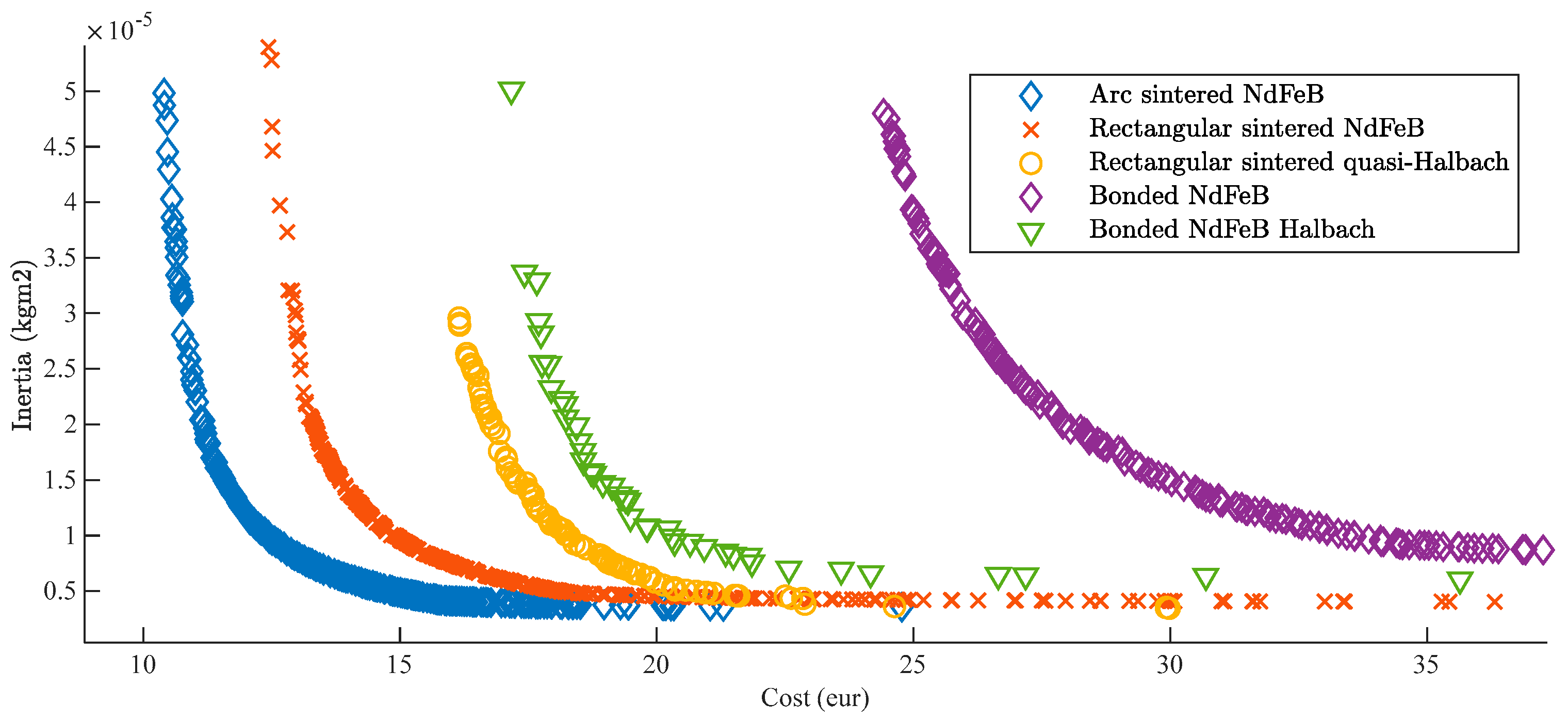
For instance, surface mounted topologies are most suitable for achieving high torque density, and so are high energy density PM materials. However, in the case of PM materials, sintered NdFeB offer only limited magnetizations and are, as such, limiting in design options. The possibility to have more varied and better-suited magnetization is also why bonded rare-earth magnet solutions were studied. Of the listed topologies, the most promising were optimized and studied in more detail using MagOpt software [19].
When setting up the design specifications, it important to note that magnetic spring will not necessarily have a linear characteristic. In fact, except for small strokes around equilibrium positions, it is more likely to produce a quasi-sinusoidal characteristic. The above mentioned linear region can be extended by specific geometries of the magnet and back-iron. However, it has been noted that this can lead to lower design efficiency. Additionally, it is not a given fact that a linear characteristic is the most suitable solution for a given application case. An example of utilizing nonlinear spring can be found in Reference [20] where stable and unstable equilibria of magnetic spring can be used instead of a locking mechanism. Under this consideration, we need an alternative to spring stiffness to translate the system design specifications into component design specifications.
Specifying stroke and potential energy of a spring is adequate since it does not over-constrain the optimization problem by imposing a desired torque characteristic. The magnetic spring potential energy can be evaluated from torque characteristic and stroke as
E = θ 1 θ 2 T ( θ ) d θ .
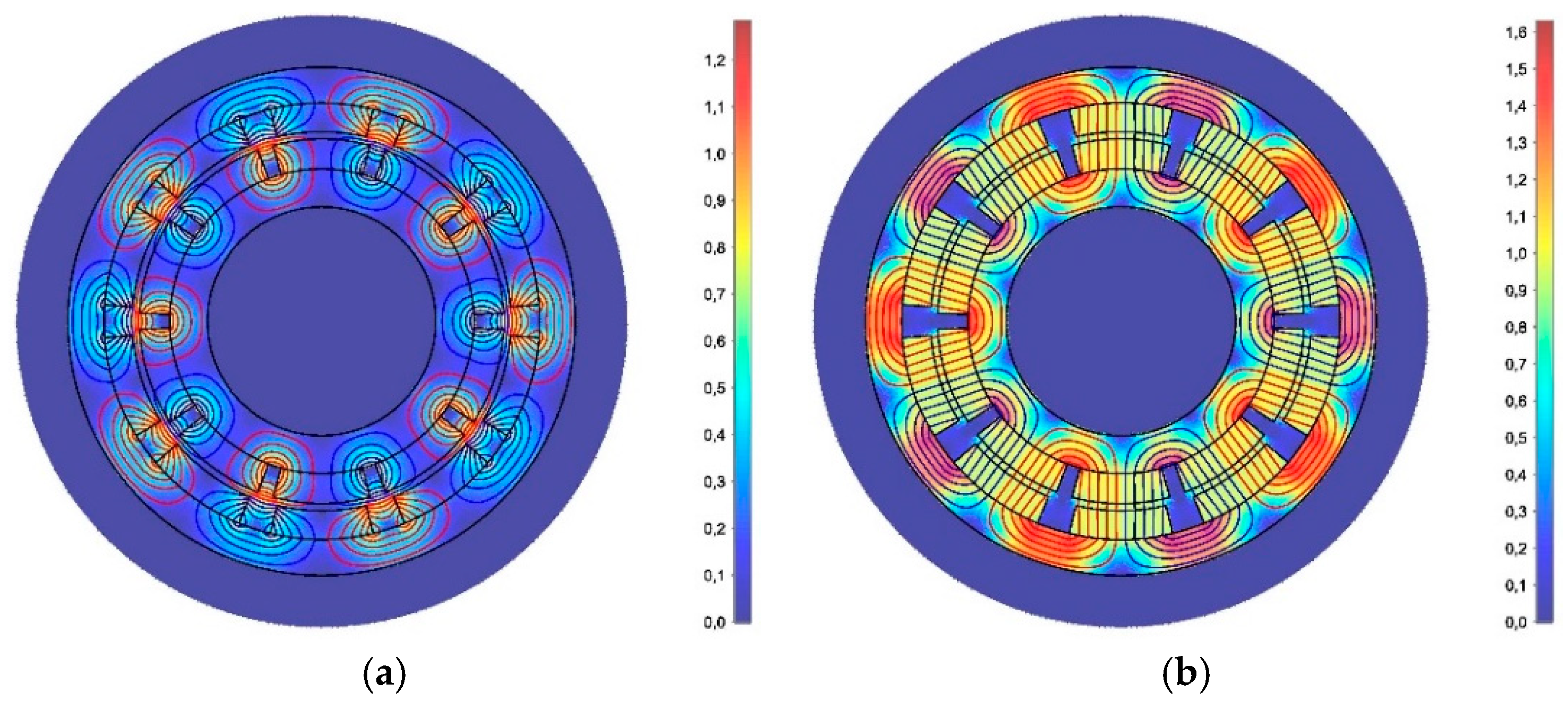
In order to evaluate each design variant, a 2D magnetostatics model of the geometry is calculated (Figure 5), for a range of θ sufficient to capture the desired rotational orders. Normally, odd higher orders, (3rd and 5th harmonic) are present for symmetric sine distortion. Therefore, in this analysis anywhere from 11 up to 21 θ points were used for a single design evaluation, with the lower numbers proven to be sufficient. For long rotors with the aspect ratio of length to diameter of more than two, the 2D approach should be sufficient, as cap effects can be disregarded. For disc geometries, on the other hand, it is necessary to use a 3D FEM. Since we are interested in high bandwidth actuators, it makes sense to focus on low inertia, long shaft solutions.
For each FEM evaluation, a list of metrics of interest can be calculated, either by pre-processing the specifications and the geometry or by post-processing the FEM solution. The considered design metrics are:
  • Torque characteristic
    Stored energy
    Stroke
    Higher harmonic content (Fourier decomposition/THD)
  • Inertia
  • Bulk material cost
  • Demagnetization
The main objective of the design is to make a spring that fits the described energy and stroke specifications while minimizing inertia and cost. Within this article, the discussed cost of magnetic spring is merely the bulk material cost and is as such most useful for comparing different topological variations of magnetic springs, but also to get a first, rough idea of the magnetic spring cost in an industrial motion system. Although, in the latter case, other cost components, such as development, manufacturing and installation costs should be considered. All of these factors are heavily influenced by the volume of production and other economic factors. The cost comparison of different magnetic spring topological variations is considered valid, under the assumption that all of the considered sintered magnet geometries use the same manufacturing technology, especially with respect to magnetization i.e., only straight or diametrical magnetizations are considered. For a thorough design optimization, the MagOpt package [19] was used together with an opensource 2D FE solver for magnetostatic problems [21]. Other listed metrics were monitored for reasons of design safety (demagnetization) and possible unwanted dynamic effects (higher harmonic content). So far, loss models have not been considered, assuming that the efficiency of a magnetic spring is very high compared to a servo-drive since ohmic losses and the drive losses are completely avoided [22] in magnetic springs.
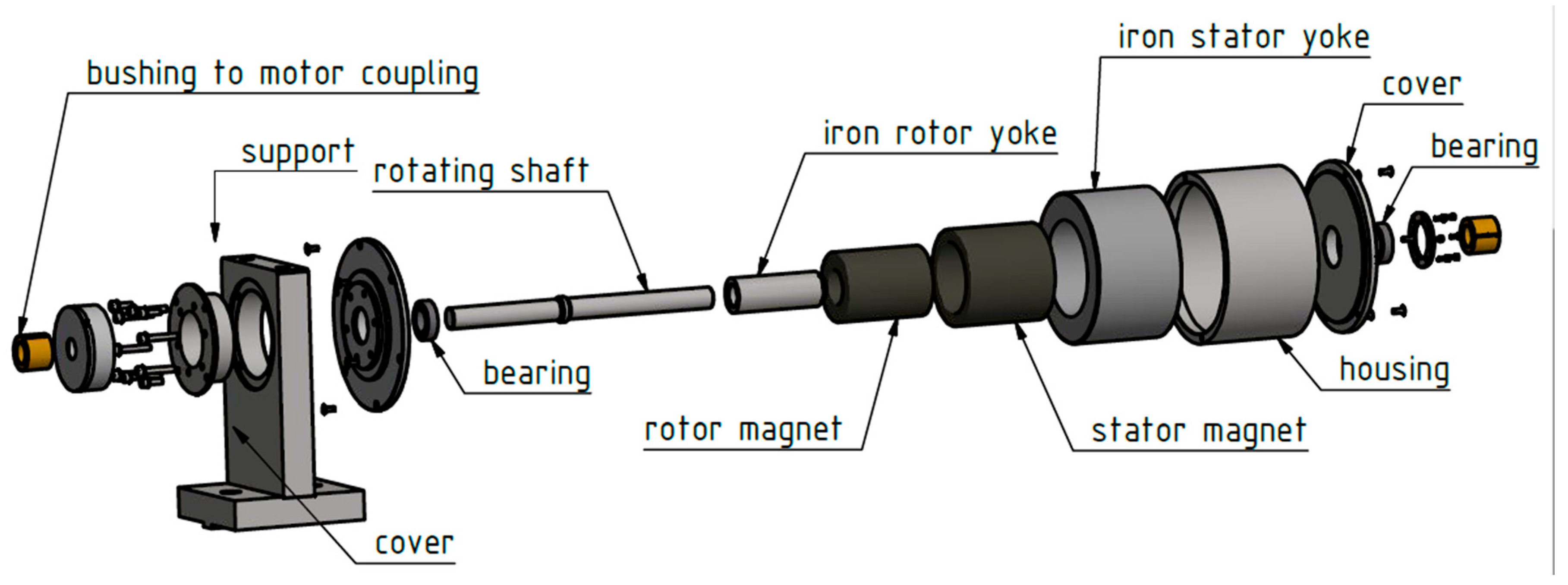
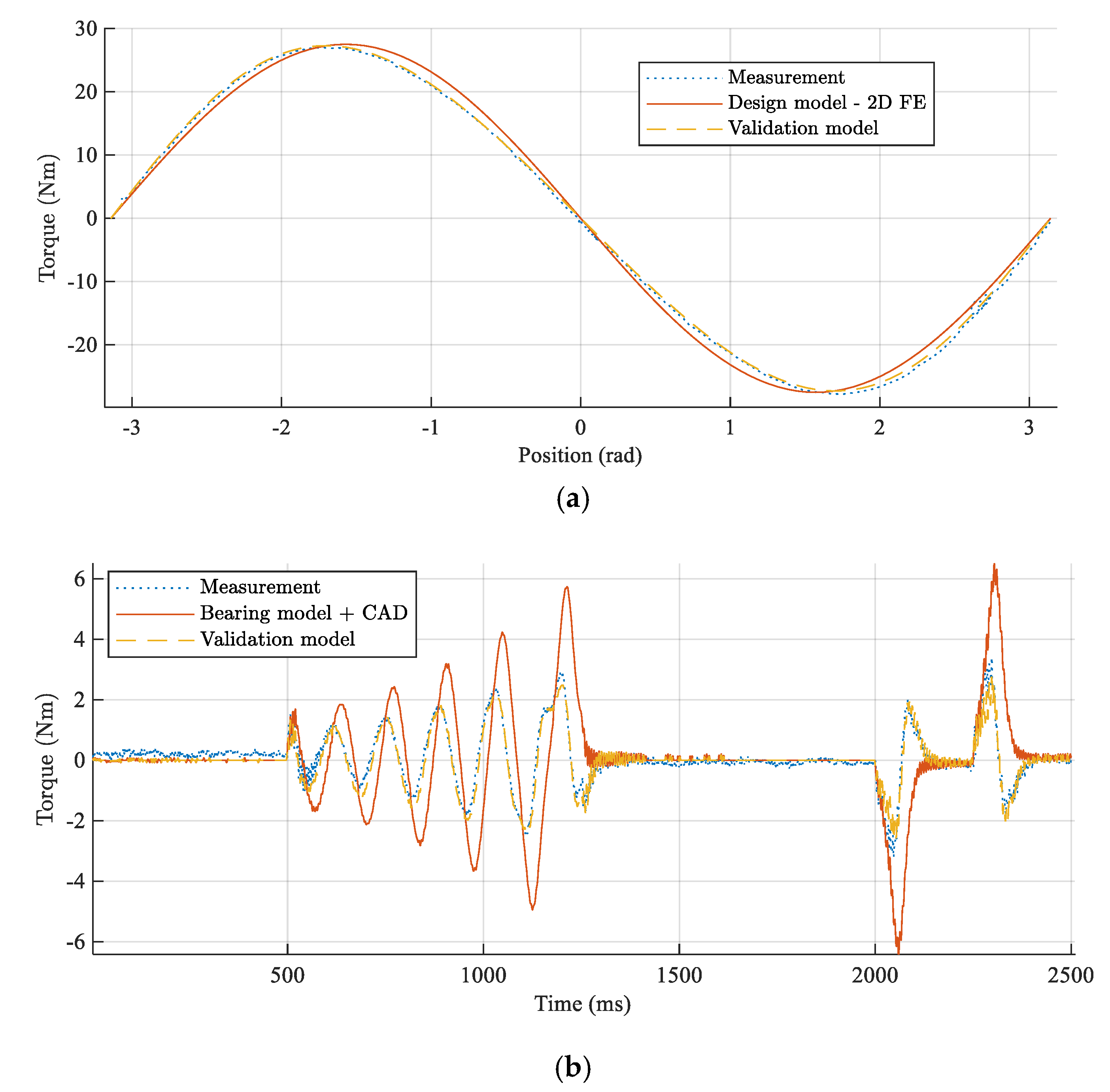
In order to validate the above described modeling approach, a prototype of a magnetic spring has been built (Figure 6). A magnetic spring consists of two diametrically magnetized ring NdFeB, N42H magnets, one on the stator and one on the rotor, with soft magnetic back iron to prevent flux leakage. For testing modularity, the spring has a built-in deep groove ball bearing. The bearing adds to the losses in the magnetic spring, which should be avoided in future designs, with a higher level of spring integration into the existing drivetrain.
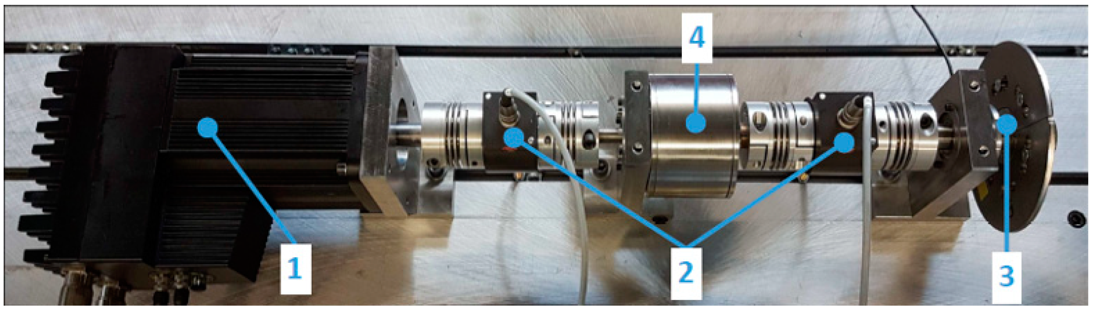
Experimental validation of the following modeling approach was conducted with a test rig, in Figure 7, that consists of a position controlled PMSM motor (1), driving an inertial wheel (3) with the assistance of spring (4). The torque sensors (2) are installed between the motor and the spring, and spring and the flywheel, using bellow couplings to avoid alignment issues or over-constrained rotation axes. Both dynamic and static experiments were conducted using the same setup. Note that here below couplings are adding serious elasticity in the system between the PMSM rotor and magnetic spring rotor but also the magnetic spring rotor and flywheel. This stiffness of the below couplings is, however, several orders of magnitude higher than that of the used magnetic spring and as such is not relevant for primary dynamics due to the reciprocating motion. For monitoring of power flows, the sensors (encoders and torque sensors), described in Table 3, are used together with fully observable controller inputs.

3. Results

3.1. Component Design Experimental Validation

The measurement results (Figure 8) show a good qualitative and quantitative fit of the static measurement and a good qualitative fit with respect to the low loss hypothesis. In Figure 8a, a slight skewing of the sinusoidal curve is visible. This phenomenon is related to the eccentricity of the magnetic center of design and the mechanical rotation axis due to the manufacturing tolerances and it can be captured in static stiffness modelled as a skewed sine due with single order eccentricity
T s t ( θ ) = A   sin ( 2 π θ T + Δ T sin θ N )
where T s t is the static torque of the magnetic spring as a function of angle θ . A is the torque amplitude in Nm. T is the period of the spring torque characteristic in radians, and depends on the pole pair number of the magnetic spring. Δ T , in radians, represents the skewing of the characteristic.
More complex aberration of the center of rotation can be captured with more addends in the sine argument, written as a Fourier decomposition, although, the most common issue of static alignment of mechanical and magnetic rotational axes results in a synchronous rotational order where N = 1 . In Table 4, the identified parameters show that, apart from skewing, the peak torque value has less than 1% error compared to the FE model.
For dynamic component identification (Figure 8b), torque and position measurements are filtered using 4th order 0-phase low pass filters with cutoff frequency at 200 Hz. The model parameters are fitted using Opti toolbox [Opti] non-linear least squares. The model of the simple magnetic spring in a direct dynamic form can be written as
T d y n = T s t ( θ ) J θ ¨ c v θ ˙ T C ( θ ˙ ) ,
where T C , is dynamic Coulomb friction with hysteresis effect. The principal intrinsic losses of the magnetic spring are expected to be caused by the velocity proportional eddy currents in the permanent magnets. This way these can be set apart from the bearing friction that is dominated by a sliding and rolling friction that is constant above a certain speed (breakaway torque) and modeled as T C . Additionally, viscous friction due to the lubricant viscosity, also contributes to bearing losses. The results of the dynamic parameter identification show that the losses are primarily dominated by the bearing friction T C . Moreover, the speed proportional component is lower than the anticipated lubrication viscosity, proposed by the a priori bearing model [23]. Therefore, based on this experiment, it is impossible to discern between bearing losses and intrinsic magnetic spring losses. Nevertheless, a clear conclusion is that magnetic spring losses are negligible compared to the other energy sinks in the highly dynamic drivetrain.
The magnetic spring assisted drivetrain shown in Figure 7 can be operated between the unstable equilibria, similar to a parallel elastic actuator with a locking mechanism [3] or an inverted pendulum. The system is operating as follows (Figure 9). At t = −0 s, the load is held in a stable equilibrium. Initially, an FF torque pulse is applied together with a negative damping controller in order to excite the natural resonance of the system (phase 1. Start-up). Due to the negative damping, the load is slowly brought in the neighborhood of the unstable equilibrium where a stable PID controller is switched on in order to hold the load in position with 0-torque control (phase 2. 0-torque wait).
Once a reciprocating motion is required, the controller starts to operate in a catch-release fashion with a small FF torque pulse initiating the motion and pushing the load towards the next unstable equilibrium. Due to the magnetic spring torque, the load is accelerated until reaching the middle point, where the spring starts to decelerate it. Upon reaching the surroundings of the next unstable equilibrium, the motor is activated again, with a feedback controller, in order to stabilize the load in the endpoint. In this fashion, the motor is delivering only the bare minimum of the required torque.
The same motor operating without a magnetic spring while driving the same load (Figure 9), requires a peak torque of 25 Nm while in case of the magnetic spring assisted setup it is only 8 Nm. Therefore, the required peak torque is approximately three times lower in a case where a magnetic spring is used. The significant reduction can also be observed in energy consumption per cycle of reciprocating motion. The energy required for operation of magnetic spring assisted drivetrain is reduced from 29.07 J per cycle to 5.05 J per cycle, signifying an almost six-fold energy reduction. Here, the energy consumption is calculated as a sum of the measured mechanical power (torque sensors, encoders) at the motor output shaft and the ohmic losses calculated from the torque reference and motor datasheet parameters (phase resistance and torque constant).
It is visible that initially, during the start-up, the energy required to initialize the spring assisted setup is higher. This is, however, not a serious downside of the spring assisted actuator, considering that in the industrial application cases the drivetrain is only seldomly initiated, before long hours of operation, making the start-up energy consumption a negligible segment of the total energy consumption. For this reason, and for the convenience of tracking the energy consumption during the operational behavior (Figure 9, phase 3, reciprocating motion) the plotted energy is reset in the middle of the experiment (Figure 9, Phase 2, 0-torque wait. Alternatively, it is also possible to run the spring assisted system at a much higher torque in order to achieve a faster transient than it is possible with the motor only. In that case, a bang-bang controller can be used to accelerate the load as quickly as possible between two end positions.

3.2. Model Based-Optimal Component Design

Detailed design optimization of the selected five most interesting topologies was done. The resulting Pareto fronts of different magnetic spring topologies can be compared for a fixed energy requirement and stroke. In Figure 10 it can be seen that sintered NdFeB is preferred over bonded magnets for reasons of both lower cost inertia. The added effect of using isotropic material (bonded NdFeB) to achieve a wider variety of magnetization is smaller than the added cost and inertia that results from lower flux densities in these materials. Interesting enough, low inertia levels can be achieved for each topology, irrelevant of the magnet geometry. However, the amount of material required to do so results in the lowest cost design with surface mounted arc magnets.
Additional conclusions regarding design rules can be drawn from optimization results through Pareto optimal parameters. In Figure 11 normalized histograms (i.e., non- dimensional value on the y-axis) of the pareto optimal designs are plotted for each of the five selected topologies, showing the parameter distribution for the optimal designs that lie on the Pareto front.
Further analysis, shows that pole pitch in quasi Halbach arrays is optimally fully pitched with pitch factor values (i.e., the ratio of magnet coverage and pole pitch) approaching 1 (Figure 11e,f), which results in closest possible design to a real Halbach magnetization. On the other hand, standard multipole array values optimally have short pitchpoles with pitch factor values between 0.75 and 0.85 in order to prevent short-circuiting of the permanent magnet flux. The specific value of pitch factor, in this case, depends on the magnetic air gap between stator and rotor magnets as this represents the magnetic resistance of the parallel flux path. Another difference between Halbach and standard multipole arrays is in the thickness of the magnets (Figure 11c,d).
Finally, the scalable 1D model of magnetic springs can be validated using both the experimental validation and the detailed FEM of the designs presented here. Note that the two designs have different requirements as well as geometry sizing, and pole pair number. The single experimental design maps into one point, while the pareto front shows a dispersion of the possible designs. Therefore, the 1D model visible in Figure 12 Should be considered as a line partitioning the feasible component space from the infeasible.

4. Discussion

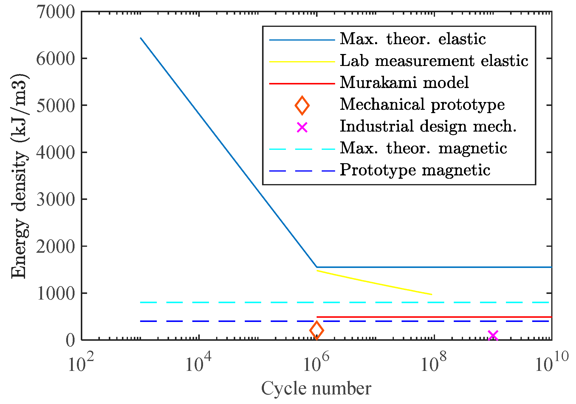
Following the optimization results, the impact of magnetic spring on system performance can be analyzed from different perspectives. To compare magnetic springs to mechanical springs side-to-side phenomenologically, maximum theoretical energy density based on first principles is considered alongside with the realistically feasible energy density following from the optimization result. Since desired lifetime has a direct influence on stress level in mechanical springs and therefore also on energy density, we can plot energy density vs. required lifetime for mechanical and magnetic springs (Figure 13).
The maximum theoretical energy density of the magnetic spring of E m a x 52 S = 828   kJ / m 3 is already higher than that of the Murakami model based gigacycle energy density of steel springs at E M u r a k a m i = 506   kJ / m 3 . The difference between feasible energy density achieved with the feasible designs is even more dramatic. With NdFeB 42H grade and arc magnets, we are able to design a magnetic spring with an energy density of E m o d e l 42 H = 404   kJ / m 3 , while a specific mechanical spring described in Reference [9] possesses an energy density of E m e c h = 210   kJ / m 3 with possible fatigue failure already at megacycles. However, it is difficult to generalize on feasible gigacycle mechanical designs for all the designs as the range of safety factors used within these applications is usually in quite a large range. Nevertheless, while being conservative we can say that the resulting increase in energy density is at least 50%, considering that the minimax design efficiencies of 0.6 achieved in this paper are larger than those in mechanical spring designs where safety factors are usually moderately higher than 2. Consequently, magnetic springs are specifically relevant for highly dynamic drivetrains in manufacturing machines e.g., a weaving loom operating shedding frames at 10 Hz reaches into megacycles after only 27.8 h and reaches well into a gigacycle regime in its standard operational age.
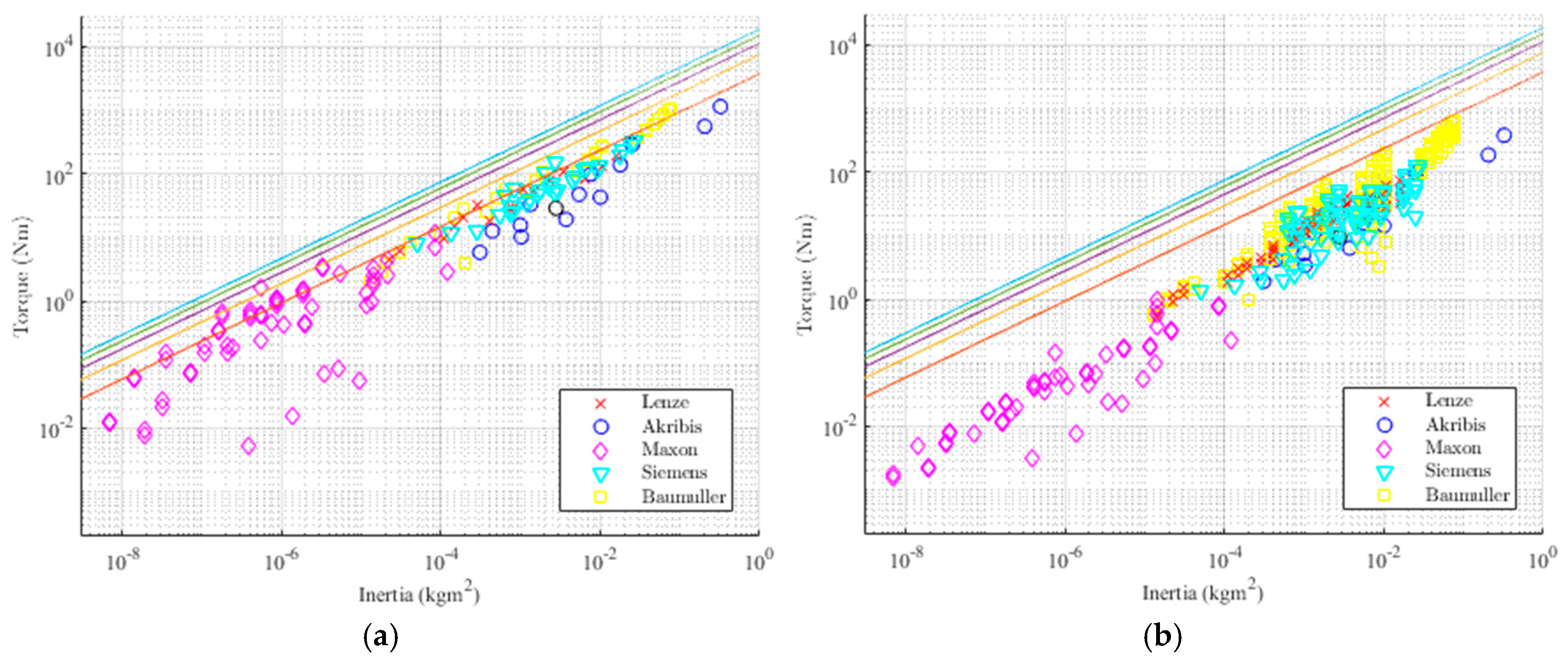
The benchmarking against PMSM is performed using a combination of real-life data from PMSM datasheets and model comparison using the developed magnetic spring modelling toolchain. Several types of servomotors are considered, with a preference for highly dynamic ones with high torque density. Extrapolation from the datasheet points can be carried out using the relation.
J = n T p e a k 5 / 3
which is valid for both springs and motors, assuming a fixed rotor aspect ratio (diameter/length). To reduce the cost and size of an electric drive solution, a reducer with transmission ratio n may be employed. However, the reflected inertia with a geared solution is always higher, given that
J = n 2 J m o t o r
and 2 > 5 / 3 . In Figure 14a only peak torques are considered, which are limited by the magnetic design of motor and spring. This results in a misleading image of rather “smaller” PMSMs (Maxon) having a higher torque density than magnetic springs with one or even two pole pairs. Note that for these “smaller” motors with natural cooling the difference between nominal torque and the peak torque is also greater. Figure 14b presents a more relevant image for highly dynamic industrial applications since here the nominal torque provided by the motor is compared to the spring peak torque.
Nominal torque depends on the thermal design of the motor and cooling circuit, and in this analysis, all of the conventional air and liquid cooling methods were considered. The allowed dynamic peak can be higher than this limit, depending on the overload potential and the dynamic nature of the load, however, for exact quantification of this effect, a more detailed system dynamics analysis, outside of the scope of this article, should be considered. Additionally, for magnetic springs no thermal limitation is considered since the losses associated with generating torque are non-existent and the dynamic losses due to the eddy currents have been shown to be negligible. In conclusion, as a result of high torque density of magnetic springs the actuator bandwidth can be systematically improved for predetermined reciprocating profiles. This effect is more significant for small air-cooled motors, and less pronounced for larger designs. For exact quantification, a more detailed study on system optimization of magnetic spring assisted drivetrains is needed, considering optimal control strategy, relative sizing of spring and motor, sizing and selection of other system components (e.g., gearbox, motion conversion mechanism), and capturing motion requirements.

5. Conclusions

A detailed component design methodology has been developed and validated. A theoretical energy density was established based on physical insight in energy stored in permanent magnets. Detailed design optimization results show that design up to 60% of material efficiency are manufacturable. Best results are achieved with surface mounted arc sintered NdFeB magnets. The modeling approach is validated for a manufactured prototype, by static and dynamic component characterization on the experimental test rig. Following these results, based on 1D scalable models of magnetic springs, the energy density of a mechanical and magnetic spring can be compared for a long lifetime. Magnetic springs have at least a 50% higher power/energy density than mechanical springs with the with the added benefit of no fatigue failure. Additionally, using 1D scalable models of magnetic springs, a comparison between torque density of magnetic springs and PMSM off-the-shelf motors shows the added value of magnetic springs for preplanned reciprocating motion systems. The added benefit is specifically dramatic for partial strokes when magnetic springs with two and more pole pairs are employed when drivetrain peak acceleration is increased by 33% for the worst case scenario.
Conceptually, also the impact of magnetic spring on system behavior is experimentally demonstrated. The results show a six times lower energy consumption, and three times lower peak torque for a magnetic spring assisted drivetrain. Future studies should, however, consider a detailed analysis of system level design of highly dynamic drivetrains and quantify the associated cost reduction resulting from possible motor downsizing and improvement in bandwidth and energy efficiency in a more systematic manner.
Based on the dynamic measurement performed on the prototype, magnetic spring losses do not seem to be a relevant issue for the design of spring assisted reciprocating drivetrains, where due to the low pole pair number, the frequency of the magnetic field is rather low. Nevertheless, the demagnetization H d e m a g field is directly influenced by the temperature, and the rise in temperature is directly caused by losses. Therefore, it is important to notice that for using magnetic spring with higher pole pair number, than considered here, for e.g., torque ripple reduction [24], demagnetization can still be a possible issue. For such cases, a better understanding of thermal behavior and losses might lead to savings related to the selection of lower temperature grade magnets related to lower Dysprosium content.
Finally, we would like to comment un utility of magnetic springs. In this article, magnetic springs are primarily intended for enabling elastic actuation in industrial applications, where this was not feasible so far, due to the catastrophic failures that can result not only in significant down times, but also damage to the machine, processed goods and operator (e.g., weaving loom or punching tool failure). Alternatively, it might be possible for magnetic spring to replace mechanical springs in applications where the use of mechanical springs is established, for reasons of reduced downtime. However, the cost of magnetic springs is still expected to be higher than that of highly commoditized mechanical springs, meaning that a trade-off study, done from a perspective of specific industrial application will be necessary in order to determine when to use the magnetic springs. The results presented in this article provide a head start in such a study.

Author Contributions

Conceptualization, B.M., W.D. (Walter Driesen) and W.D. (Wim Desmet); Data curation, B.M.; Formal analysis, B.M.; Funding acquisition, W.D. (Walter Driesen) and W.D. (Wim Desmet); Investigation, B.M.; Methodology, B.M., B.L., W.D. (Walter Driesen) and W.D. (Wim Desmet); Supervision, W.D. (Walter Driesen) and W.D. (Wim Desmet); Validation, B.M.; Visualization., B.M.; Writing – original draft, B.M.; Writing – review & editing, B.M., B.L., W.D. (Walter Driesen) and W.D. (Wim Desmet).

Funding

The research of B. Mrak as an Early Stage Researcher was funded by a grant within the European Project EMVeM Marie Curie Initial Training Network (GA 315967). This research was partially supported by Flanders Make, the strategic research centre for the manufacturing industry within Flanders Make project Profensto_icon.

Acknowledgments

The authors would like to thank Linz Center of Mechatronics GmbH and Siegfried Silber for their support through the use of MagOpt software and the associated infrastructure.

Conflicts of Interest

The authors declare no conflict of interest.

References

  1. Alexander, R.M. Three Uses for Springs in Legged Locomotion. Int. J. Robot. Res. 1990, 9, 53–61. [Google Scholar] [CrossRef]
  2. Paluska, D.; Herr, H. The effect of series elasticity on actuator power and work output: Implications for robotic and prosthetic joint design. Robot. Auton. Syst. 2006, 54, 667–673. [Google Scholar] [CrossRef]
  3. Vanderborght, B.; Verrelst, B.; Van Ham, R.; Van Damme, M.; Lefeber, D.; Meira, Y.; Duran, B.; Beyl, P. Exploiting natural dynamics to reduce energy consumption by controlling the compliance of soft actuators. Int. J. Robot. Res. 2006, 25, 343–358. [Google Scholar] [CrossRef]
  4. Mettin, U.; La Hera, P.X.; Freidovich, L.B.; Shiriaev, A.S. Parallel Elastic Actuators as a Control Tool for Preplanned Trajectories of Underactuated Mechanical Systems. Int. J. Robot. Res. 2010, 29, 1186–1198. [Google Scholar] [CrossRef]
  5. Bathias, C.; Paris, P.C. Gigacycle Fatigue in Mechanical Practice; CRC Press: Boca Raton, FL, USA, 2004; ISBN 9780203020609. [Google Scholar]
  6. Puff, R.; Barbieri, R. Effect of non-metallic inclusions on the fatigue strength of helical spring wire. Eng. Fail. Anal. 2014, 44, 441–454. [Google Scholar] [CrossRef]
  7. Abe, T.; Furuya, Y.; Matsuoka, S. Gigacycle fatigue properties of 1800 MPa class spring steels. Fatigue Fract. Eng. Mater. Struct. 2004, 27, 159–167. [Google Scholar] [CrossRef]
  8. Serbino, E.M.; Tschiptschin, A.P. Fatigue behavior of bainitic and martensitic super clean Cr-Si high strength steels. Int. J. Fatigue 2014, 61, 87–92. [Google Scholar] [CrossRef]
  9. Reinholz, B.A.; Seethaler, R.J.; Electromechanical, A. Experimental Validation of a Cogging-Torque-Assisted Valve Actuation System for Internal Combustion Engines. IEEE/ASME Trans. Mechatron. 2016, 21, 453–459. [Google Scholar] [CrossRef]
  10. Sudano, A.; Tagliamonte, N.L.; Accoto, D.; Guglielmelli, E. A resonant parallel elastic actuator for biorobotic applications. In Proceedings of the IEEE International Conference on Intelligent Robots and Systems, Chicago, IL, USA, 14–18 September 2014; pp. 2815–2820. [Google Scholar]
  11. Mrak, B.; Driesen, W.; Desmet, W. Magnetic Springs—Fast Energy Storage for Reciprocating Industrial Drivetrains. In Proceedings of the ABCM International Congress of Mechanical Engineering, Rio de Janeiro, Brazil, 17–21 May 2015; Volume 23. [Google Scholar]
  12. Patt, P.J. Design and testing of a coaxial linear magnetic spring with integral linear motor. IEEE Trans. Magn. 1985, 21, 1759–1761. [Google Scholar] [CrossRef]
  13. Poltschak, F.; Ebetshuber, P. Design of Integrated Magnetic Springs for Linear Oscillatory Actuators. IEEE Trans. Ind. Appl. 2018, 54, 2185–2192. [Google Scholar] [CrossRef]
  14. Mizuno, T.; Takasaki, M.; Kishita, D.; Hirakawa, K. Vibration isolation system combining zero-power magnetic suspension with springs. Control Eng. Pract. 2007, 15, 187–196. [Google Scholar] [CrossRef]
  15. Boisclair, J.; Richard, P.; Lalibert, T. Gravity Compensation of Robotic Manipulators Using Cylindrical Halbach Arrays. IEEE/ASME Trans. Mechatron. 2017, 22, 457–464. [Google Scholar] [CrossRef]
  16. Mrak, B.; Lenaerts, B.; Driesen, W.; Desmet, W. Optimal Design of Magnetic Springs; Enabling High Life Cycle Elastic Actuators. In Proceedings of the 16th International Symposium on Magnetic Bearings ISMB16, Beijing, China, 13–17 August 2018. [Google Scholar]
  17. Christen, T.; Ohler, C. Optimizing energy storage devices using Ragone plots. J. Power Sources 2002, 110, 107–116. [Google Scholar] [CrossRef]
  18. Spittel, M.; Spittel, T. 4.2 Young’s modulus of steel. In Metal Forming Data of Ferrous Alloys—Deformation Behaviour; Warlimont, H., Ed.; Springer: Berlin/Heidelberg, Germany, 2009; pp. 85–88. ISBN 978-3-540-44760-3. [Google Scholar]
  19. Silber, S.; Koppelstätter, W.; Weidenholzer, G.; Bramerdorfer, G. MagOpt—Optimization tool for mechatronic components. In Proceedings of the 14th International Symposium on Magnetic Bearings, Linz, Austria, 11–14 August 2014; pp. 243–246. [Google Scholar]
  20. King, C.; Beaman, J.J.; Sreenivasan, S.V.; Campbell, M. Multistable Equilibrium System Design Methodology and Demonstration. J. Mech. Des. 2004, 126, 1036. [Google Scholar] [CrossRef]
  21. Meeker, D.C. Finite Element Method Magnetics, Version 4.2 (28Feb2018 Build). Available online: http://www.femm.info (accessed on 19 February 2019).
  22. Wang, J.; Atallah, K.; Chin, R.; Arshad, W.M.; Lendenmann, H. Rotor eddy-current loss in permanent-magnet brushless AC machines. IEEE Trans. Magn. 2010, 46, 2701–2707. [Google Scholar] [CrossRef]
  23. SKF Bearing Calculator. Available online: webtools3.skf.com/BearingCalc/ (accessed on 19 February 2019).
  24. Mrak, B.; Adduci, R.; Weckx, S.; Driesen, W.; Desmet, W. Novel phase-bound magnetic vibration absorber for improved NVH performance of a wind turbine gearbox. In Proceedings of the International Conference on Noise and Vibration Engineering ISMA2018 Including USD2018, Leuven, Belgium, 17–19 September 2018. [Google Scholar]
Figure 1. Conceptual drawing of (a) a rotational motion (torsional) magnetic spring and (b) linear motion (translational) and figure indicating torque and force generated due to the displacement.
Actuators 08 00018 g001
Figure 2. The co-dependent nature of the system design and component design cycles through linked modelling approaches.
Actuators 08 00018 g002
Figure 3. The potential energy of springs; permanent magnet energy density calculated from B-H characteristic is a measure of the maximum theoretical energy density of a magnetic spring.
Actuators 08 00018 g003
Figure 4. Overview of parametrized PM rotor topologies used in design optimization; (a) arc surface mounted magnets; (b) rectangular surface mounted magnets; (c) ring magnet—special case of arc surface mounted magnet; (d) buried arc magnets; (e) buried rectangular magnets; (f) internal magnets.
Actuators 08 00018 g004
Figure 5. Overview of parametrized PM rotor topologies used in design optimization with surface mounted topologies a–c being most suitable for high torque density; (a) anti-aligned magnets resulting in unstable equilibrium with maximum energy stored in PM; (b) aligned magnets resulting in stable equilibrium; no energy stored in PM.
Actuators 08 00018 g005
Figure 6. Explosion view of the prototyped magnetic spring design.
Actuators 08 00018 g006
Figure 7. Experimental test rig consisting of a (1) position controlled PMSM, (2) torque sensors, (3) flywheel—load and the developed prototype of a magnetic spring (4).
Actuators 08 00018 g007
Figure 8. Component validation (a) static measurement of magnetic spring torque characteristic (b) dynamic measurement for identification of spring inertia and losses.
Actuators 08 00018 g008
Figure 9. Proof-of-concept. Comparison of dynamic operational data for a magnetic spring with minimum motor torque vs. no spring setup with peak torque operation; controller structure and tuning have an impact on the exact values.
Actuators 08 00018 g009
Figure 10. Optimization results plotted as Pareto-fronts for five stator and rotor topologies selected after design space pruning for different energy and stroke specifications.
Actuators 08 00018 g010
Figure 11. Optimal parameters histograms for five selected stator and rotor topologies selected after design space pruning.
Actuators 08 00018 g011
Figure 12. Validation of 1D scaling model for (a) magnetic spring inertia and (b) magnetic spring bulk material cost using experimental data and virtual validation data.
Actuators 08 00018 g012aActuators 08 00018 g012b
Figure 13. Benchmarking magnetic springs vs. mechanical springs; magnetic springs have increasingly higher energy density for high life cycle numbers.
Actuators 08 00018 g013
Figure 14. Benchmarking torque density of magnetic springs (1D scaling model) with pole pair numbers Npp = 1–5 vs. off-the-shelf highly dynamic PMSM (a) peak torque vs. inertia and (b) nominal torque vs. inertia.
Actuators 08 00018 g014
Table 1. Overview of considered permanent magnet materials.
GradeN33H 1N42H 1S32H 2Pi-95HR 3
Energy density (kJ/m3)521673510173
BHmax   ( kJ / m 3 )26333425585
Max temperature (°C)120120350125
1 sintered Neodymium Iron Boron (NdFeB); 2 sintered Samarium Cobalt (SmCo), both anistropic material with limited magnetization; 3 plasto bonded NdFeB, isotropic material with free magnetization.
Table 2. Overview of evaluated topological choices.
PropertyVariant
PM materialIsotropic, anisotropic temperature grade
MagnetizationStraight-diametrical, radial, tangential, Halbach
Magnetic arrayQuasi-Halbach, multipole, over-segmented pole
Segment shapeArc-segment, rectangular, bread loaf
Mounting methodSurface, buried, internal
Table 3. Experimental setup sensor specifications.
LocationSensor TypeRange/Resolution
Motor −1Integrated encoder motor8192 pulse/rev
Flywheel −3
Spring −4
2× high accuracy optical encoder327,680 pulse/rev
(14 bit with 40× interpolation)
Torque Sensors −2Dynamic Torque Sensor±100 Nm/±10 V
Table 4. Component design validation results.
ParameterMeasured/Estimated Std. ErrorModeled Value
Inertia (kgm2)0.0004207724.91751 × 10−60.00042 1
Viscous friction coefficient (Nms/rad)0.00195418 3.28588 × 10−40.05 2
Coulomb friction torque (Nm)0.1260570.01563860.432 3
Torque Amplitude (Nm)27.2840.0075743127.5
Skewing (rad)0.1327525.30995 × 10−40
1 CAD drawing of spring prototype; 2 based on bearing lubricant viscosity; 3 based on sliding torque; both from SKF model for W 61902-2Z bearing under C load.

