Abstract
Research interests of compact magnetically levitated motors have been strongly increased in development of durable and biocompatible mechanical circulatory support (MCS) devices for pediatric heart disease patients. In this study, an ultra-compact axial gap type self-bearing motor with 5-degrees of freedom (DOF) active control for use in pediatric MCS devices has been developed. The motor consists of two identical motor stators and a centrifugal levitated rotor. This paper investigated a design improvement of the magnetic circuit for the self-bearing motor undergoing development in order to diminish energy input by enhancing magnetic suspension and rotation performances. Geometries of the motor were refined based on numerical calculation and three-dimensional (3D) magnetic field analysis. The modified motor can achieve higher suspension force and torque characteristics than that of a previously developed prototype motor. Oscillation of the levitated rotor was significantly suppressed by 5-DOF control over rotating speeds up to 7000 rpm with lower energy input, indicating efficacy of the design refinement of the motor.
1. Introduction
Mechanical circulatory support (MCS) is widely used for heart disease therapy. However, clinically available and implantable MCS devices are not applicable for pediatric patients, which have small body surface area (BSA < 0.7 mm2) due to anatomical limitations [1,2]. Almost all pediatric patients have to rely on using EXCOR pediatric ventricular assist device (VAD), which is a extracorporeal pulsatile flow pump developed by Berlin Heart Inc. in Germany [3]. Pulsatile devices with diaphragm and valve configurations potentially limit a device’s lifetime and have the risk of thrombosis. Currently, there have been increasing research interests in pediatric heart treatment with implantable rotary MCS devices specifically designed for pediatric circulatory support [4]. In 2010, MCS device development for pediatric patients was supported as a national project named PumpKIN (Pump for kids, infants and neonates) in the United States (US) [1,2,4]. A tiny rotary MCS device (Jarvik2015) for pediatric circulation is being developed by Jarvik Heart Inc. in the US [5,6,7]. However, the Jarvik device is now facing technical difficulties such as deterioration of mechanical durability, blood clotting and blood destruction, due to a mechanically contacting bearing to suspend a spinning rotor impeller. Hence, the development of next-generation MCS devices that can completely levitate a rotating impeller are in demand due to its high durability and better blood compatibility.
A magnetic suspension system is one of the strongest candidates to suspend the rotating impeller without mechanical contact. The biggest advantages of maglev technology are its high-speed motor drive, less heat generation due to no material wear, zero friction, less blood trauma, anti-thrombogenicity and increased mechanical reliability. In one of the earliest studies, 5-DOF-controlled maglev motors were developed [8,9]. The maglev system indicated high suspension stability, however, the device needed to be bigger due to the larger number of actuators: two radial magnetic bearings and two axial magnetic bearings. Miniaturization of the magnetic suspension system has a significant role in success of pediatric MCS device development. Reduction of actively controlled positions is a general strategy to miniaturize the magnetic suspension systems. For example, single DOF-controlled maglev systems, which are utilizing passive stability using magnetic coupling force or repulsive PM magnetic bearings to suspend the non-controlled DOF, were developed to achieve a simple structure and compact device size [10,11,12,13,14,15,16]. However, a larger number of passively stabilized axes potentially causes significant deterioration of suspension stability of the magnetic system. Hence, 2-degrees of freedom (DOF)-controlled radial maglev motors and 3-DOF-controlled double stator axial maglev motors have often been developed in blood pump applications [17,18,19,20,21,22,23,24]. These miniaturized maglev motors are successfully applied to implantable and extracorporeal MCS devices for adult patients, whereas further miniaturization of the maglev motors is required for use in rotary pediatric MCS devices. In extremely small magnetic suspension systems, there is a limitation of passive stabilization in multiple axes because the system cannot have sufficient capacity of passive stiffness and suspension force due to few spaces to have enough permanent magnet volume and turn number of control windings. Hence, a technical breakthrough is needed to achieve an ultra-compact magnetic system.
This study developed a compact pediatric MCS device with a novel self-bearing motor utilizing a 5-DOF-control concept that was newly developed in our laboratory, and the developed device demonstrated noncontact suspension and sufficient pump performance [25,26,27,28]. However, further improvement of magnetic suspension stability is necessary to achieve higher mechanical reliability and energy conservation system required for clinically applicable MCS devices. In this paper, design improvement of magnetic circuit for the 5-DOF-controlled self-bearing motor was investigated to enhance the magnetic suspension performance and energy efficiency by using theoretical calculation and three-dimensional (3D) finite element method (FEM) analysis. Static force and torque characteristics [28], dynamic suspension performance and energy consumption of the improved maglev motor with 5-DOF control are evaluated.
2. Materials and Methods
2.1. 5-DOF-Controlled Self-Bearing Motor for Pediatric Ventricular Assist Device (VAD)
2.1.1. Over View of Maglev Pediatric VAD with 5-DOF-Controlled Self-Bearing Motor
The 5-DOF-controlled self-bearing motor is driven as an axial gap type surface permanent magnet synchronous motor, which has 6-slot and 4-pole structure. Figure 1 shows a schematic of the self-bearing motor which is consists of two identical motor stators and a levitated impeller. The levitated impeller is axially suspended with the both stators. Integrated windings for suspension and rotation control are wound on each stator tooth. A motor torque and a suspension force are produced with double stator mechanism which can enhance motor torque and radial passive stability.
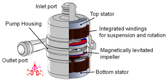
Figure 1.
Structure of pediatric ventricular assist device with the axial gap type double stator 5-degrees of freedom (5-DOF)-controlled self-bearing motor.
An axial position (z) and rotating speed (ωz) are actively regulated with a 4-pole control magnetic field. Radial positions (x and y) and tilting angles (θx and θx) are actively regulated with a 2-pole control magnetic field. 5-DOF of impeller postures are independently regulated by overlapping the different control magnetic fields in the magnetic gap [27]. A developed centrifugal blood pump for pediatric patients can regulate flow rate from 0.5 to 2.5 L/min against head pressure of around 100 mmHg at rotating speeds of 4500–5500 rpm.
2.1.2. Characterization of Suspension Force and Torque
The motor produces axial suspension force and rotating torque with a single rotating magnetic field based on vector control algorithm. An axial position (z) of the levitated impeller is actively regulated by field strengthening and field weakening as shown in Figure 2. A rotating speed (ωz) of the rotor is controlled by conventional q-axis current regulation. The axial suspension force and the rotating torque are linearly produced with d-axis current id and q-axis current iq.
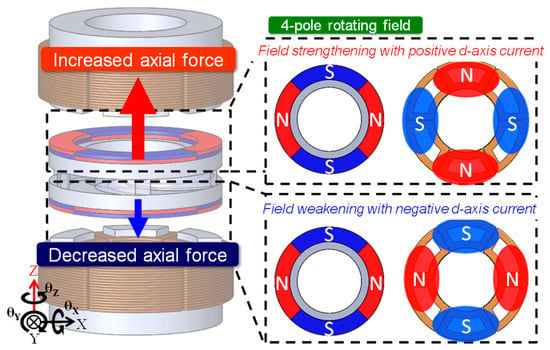
Figure 2.
Axial position control by utilizing field strengthening and field weakening.
Inclination angles (θx and θy) and radial positions (x and y) of the levitated rotor can be controlled with p ± 2 pole algorithm. The control magnetic field can simultaneously produce an inclination torque and a radial suspension force. Inclination torque around the y-axis and the radial suspension force in x direction are produced with the double stator mechanism as shown in Figure 3. The magnitude and the direction of the inclination torque and the radial suspension force can be linearly regulated with respect to excitation current supplied to the top stator and the bottom stator as following equations.
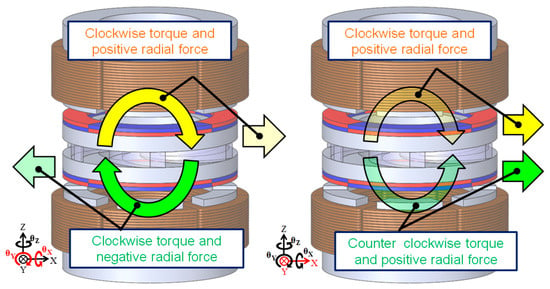
Figure 3.
Inclination and radial position control with p ±2 pole rotating magnetic field.
2.2. Suspension Force and Torque Enhancement with Modified Magnetic Circuit of the Maglev Motor
2.2.1. Design Strategy of Suspension Performance Enhancement
The motor uses magnetic flux density produced by the permanent magnet as a main flux density to produce the suspension force and the rotating torque. Enhancement of the permanent magnet flux contributes to higher suspension force production. However, in miniaturized motor, there is difficulty to have sufficiently large cross-sectional area of the magnetic flux path, and it has possibility of deterioration of magnetic suspension force due to the magnetic saturation. Furthermore, excessively increased negative stiffness due to the high magnetic intensity potentially deteriorate controllability of the magnetic system. Hence, well design of the magnetic circuit which can keep a good balance between magnetic flux density produced by the permanent magnet and electromagnet is required to achieve sufficient magnetic suspension stability. In this study, design goal is to enhance the suspension force produced by the electromagnet without change of non-excited axial attractive force for avoiding instability caused due to the axial negative stiffness.
2.2.2. Design Refinement of Magnetic Circuit for the 5-DOF-Controlled Self-Bearing Motor to Enhance the Suspension Force, the Motor Torque and Reduce the Energy Input
Design improvement of a magnetic circuit for the 5-DOF-controlled self-bearing motor was performed based on following design strategy to enhance the magnetic suspension performance. (1) Keeping device size such as the outer diameter of 22 mm, the total height of 33 mm and the total volume of the previously developed prototype motor. (2) Maintaining the axial negative stiffness kz within ±10% of that produced by the previously developed prototype motor. (3) Maximizing the force coefficient in the axial direction ki defined as a slope of the suspension force to excitation current.
Geometries representatively characterizing the magnetic circuit of the self-bearing motor: pole height lp, pole cross sectional area Ap, magnetic gap length lg and permanent magnet thickness lm, were numerically designed with theoretical calculation and fixed by using 3-D FEM magnetic field analysis as shown in Figure 4. Height and cross-sectional area of the stator pole were determined as 9.3 mm and 17.0 mm2 based on the theoretical calculation. These geometries can increase in a turn numbers of coils and effectively maximize the force coefficient with slight change of the negative stiffness and the non-excited force. Parametric study in the magnetic gap length and the PM thickness were then performed. Variable parameters of the magnetic gap length of 1.3–1.7 mm and the PM thickness of 0.8–1.2 mm were chosen considering fabrication. Each combination of the magnetic gap length and PM thickness were simulated, and the non-excited axial negative stiffness kz and the force coefficient ki were estimated. A suspension index is defined as ratio of the force coefficient to the negative stiffness, which indicates rotor displacement with respect to excitation current of 1 A. The geometry which can achieve the biggest suspension index and satisfy the above design strategy was chosen as optimal design of the motor, which achieves well suspension performance with lower energy input.
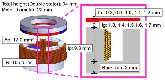
Figure 4.
Variable geometries of magnetic circuit for the self-bearing motor in design improvement using 3-D finite element method (FEM) magnetic field simulation.
The numerically estimated force coefficient and non-excited attractive force of the self-bearing motor with different geometries in the magnetic gap length and the PM thickness are shown in Figure 5. The suspension index in each motor geometry is listed in Table 1. Red and yellow colored cells indicate satisfying design requirements in the negative stiffness and the force coefficient. The optimal geometry in the FEM simulation to maximize the force coefficient (ki < 1.2 N/A) and maintain the axial negative stiffness (15.2 N/mm < kz < 18.6 N/mm) is the shortest magnetic gap length of 1.3 mm and the thinnest PM of 0.8 mm as shown in red colored cell in Table 1. The force coefficient and the negative stiffness of the optimally designed motor are 2.0 N/A and 17.1 N/mm. Deterioration of the magnetic flux density with reduction of the PM thickness can be compensated by reducing the magnetic gap length. The shorter magnetic gap length and the thinner PM thickness can reduce magnetic resistance for the electromagnet and effectively enhance the magnetic suspension force production with excitation current. The geometries of the previously developed prototype motor and the improved motor with the final design are summarized in Table 2.

Figure 5.
Force coefficient and negative stiffness of the motor with different magnetic gap length and permanent magnet thickness.

Table 1.
Estimated results of suspension index with different permanent magnet thickness and magnetic gap length.

Table 2.
Motor geometries of the prototype motor and the improved motor.
2.3. Developed System of 5-DOF-Controlled Maglev Motor with Modified Magnetic Circuit
2.3.1. Fabrication of 5-DOF-Controlled Maglev Motor
A 5-DOF-controlled self-bearing motor for pediatric VAD shown in Figure 6 was developed referring to motor geometries determined by using 3D FEM magnetic field analysis. The outer diameter and the total height are 22 mm and 33 mm. The length of magnetic gap of the developed motor is set to 1.3 mm. The material used for magnetic core of the motor stator and the rotor back iron is soft magnetic iron (SUY-1). The permanent magnets of 0.8 mm thickness are made of Nd- Fe-B, that has coercivity and residual flux density of 907 kA/m and 1.36 T, respectively. Concentrated cupper windings of 105 turns are wound on each stator tooth. Pump clearance between the pump casing and levitated rotor in the axial and radial direction are 0.3 mm and 0.5 mm.
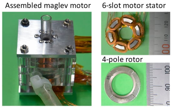
Figure 6.
Developed 5-DOF-controlled maglev motor with modified magnetic circuit. Pump casing with sensor holder, motor stator and rotor with permanent magnets.
2.3.2. Control System for Magnetic Levitation and Rotation with Digital PID Controllers
Digital PID controllers are implemented on a microprocessor board MicrolabBox (dSPACE GmbH, Paderborn Germany) with MATLAB/Simlink for 5-DOF active control. Figure 7 shows a schematic diagram of a 5-DOF control system. An axial position and inclination angles around the x and y axes of the levitated rotor are measured by three eddy current sensors (PU-03A, Applied Electronics Corporation). Radial positions of the levitated rotor in x and y direction are measured with other two eddy current sensors. A rotating angle of the levitated rotor is determined by outputs of three Hall effect sensors (Asahi KASEI Corporation) with a sensitivity of a 30-degree electrical angle. The rotating speed is calculated by time derivative of the rotating angle. Required current to produce the control magnetic flux density integrating three phase two-pole field and three-phase four-pole field synchronized with rotating PM field is calculated with PID controllers and is independently supplied to each coil by power amplifier (PA12A, Apex Microtechnology Corporation). Sampling and control frequency is 10 kHz. Control gains of the digital PID controllers for magnetic suspension and rotation were determined based on the previously measured motor suspension force and torque characteristics, and then, manually tuned in dynamic performance evaluation.
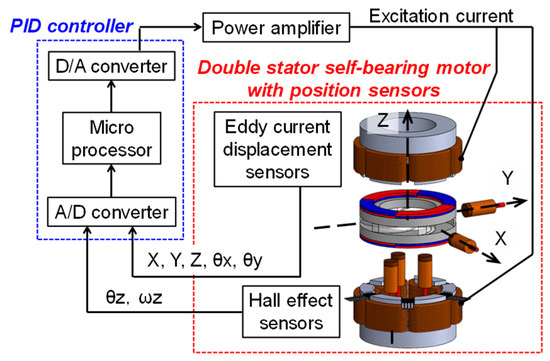
Figure 7.
Schematic diagram of control system for 5-DOF-controlled maglev motor with position sensor, PID controller implemented in the microprocessor and power amplifier.
A block diagram for axial position and rotation control, inclination angle and radial position control are shown in Figure 8 and Figure 9, respectively. Positive and negative d-axis current are determined by a PID feedback loop to produce an axial suspension force. q-axis current of both stators is regulated with a PI feedback loop for a conventional rotating speed control. Required current for inclination angle and radial position control are calculated by the other four PID feedback loops to determine amplitude and phase angle of two-pole rotating magnetic field produced by the top and bottom stators. PID gains for the position control and PI gains for the rotating speed control were set using a limit sensitivity method, and then manually tuned as shown in Table 3. Control gains of PID/PI controller of the previously developed prototype motor are also listed in Table 3.
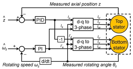
Figure 8.
Block diagram of feedback loop for the axial position and the rotating speed regulation with d-q current regulation.
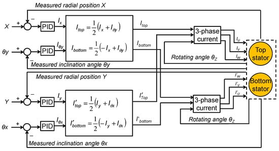
Figure 9.
Block diagram of feedback loop for the inclination and the radial position control based on P +/- 2 pole algorithm.

Table 3.
Control gains for impeller positioning and rotating speed regulation.
2.4. Magnetic Suspension Performance Evaluation of the Newly Developed Maglev Motor
2.4.1. Magnetic Flux Distribution Measurement and Static Magnetic Suspension Force and Torque Characteristics Measurement
Magnetic flux distribution produced by the rotor permanent magnets in the magnetic gap was measured without excitation. Four/two pole magnetic flux density produced by the electromagnet at excitation current of 1 A were then measured without the rotor permanent magnets. After that, static magnetic suspension force and torque characteristics: an axial negative stiffness kz, a radial stiffness kr, and suspension force of the designed motor was evaluated at excitation current of 1 A and magnetic gap length of 1.3 mm. The axial and radial suspension force were measured with load cell, and the inclination torque was calculated as a product of the measured force and rotor radius.
2.4.2. Dynamic Characteristics of Developed 5-DOF-controlled Maglev Motor
The rotor was magnetically levitated in water medium with 5-DOF control. The water flow was shut off by closed outlet port of the centrifugal pump to evaluate basic magnetic suspension characteristics by minimizing hydraulic force disturbance. Magnetic suspension performance with respect to increase in the rotating speed of the rotor was evaluated. The rotating speed was increased from 1000 rpm to 7000 rpm. Oscillation amplitude in axial direction and radial direction, maximum inclination angle around x and y axes, and power consumption of the motor during magnetic levitation and rotation were evaluated. The maximum oscillation amplitude was defined as half of the peak-to-peak value of rotor vibration.
3. Results
The measured magnetic flux density is shown in Figure 10. The magnetic flux density produced by the rotor permanent magnets did not significant difference between the prototype motor and the improved motor. In contrast, the magnetic flux density produced by the electromagnet of the improved motor significantly increased. The peak of the four/two pole magnetic flux density produced by the improved motor increased by 61% and 76% compare to the prototype motor.
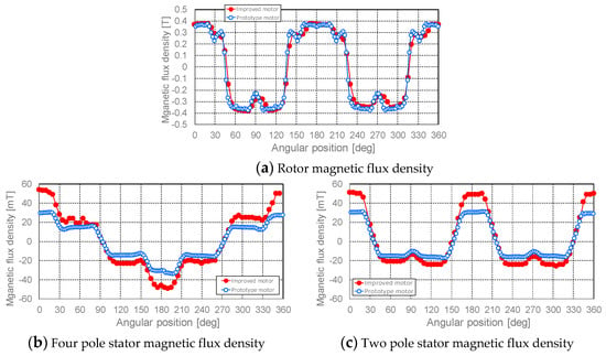
Figure 10.
Magnetic flux density distribution in the magnetic gap. (a) Four pole magnetic flux density produced by the rotor magnet. (b) Four pole magnetic flux density for the axial position and the rotation control. (c) Two pole magnetic flux density for the radial position and the inclination control.
Static suspension characteristics: stiffness, suspension force and torque, of the developed maglev motor which has the modified magnetic circuit and the previously developed maglev motor are shown together in Figure 11. The axial negative stiffness of the improved motor decreased by 17%, however, the radial stiffness was not significantly changed. The deterioration of the radial passive stability did not occur. The axial suspension force increased by 50 %, and the radial suspension force slightly decreased. Both the inclination torque and the rotating torque increased by 84% and 34%, respectively.
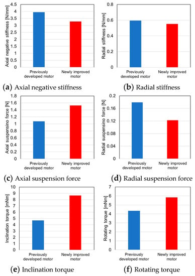
Figure 11.
Static suspension characteristics of the developed maglev motor. (a,b) Axial and radial stiffness. (c,d) Magnetic suspension force in axial and radial direction at excitation current of 1 A. (e,f) Torque characteristics at excitation current of 1A.
The improved motor successfully achieves non-contact levitation and rotation up to the rotating speed of 7000 rpm. The maximum axial and radial oscillation amplitude and the maximum inclination angle around x and y axes with respect to the increase in the rotating speed of the levitated rotor are shown in Figure 12, Figure 13 and Figure 14. In the lower speed range of 1000–3000 rpm, the oscillation amplitude of the levitated rotor was slightly increased in the prototype motor. In contrast, the oscillation amplitude in axial and radial direction, and the inclination angle of the improved motor were significantly suppressed around 20 μm, 100 μm and 0.4 degrees over every operational speed by enhancement of the suspension characteristics. The power consumption of the developed motor during magnetic levitation and rotation was shown in Figure 15, and it was in the range of 1–6 W at the rotating speeds of 1000–7000 rpm.
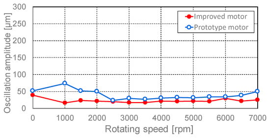
Figure 12.
Maximum oscillation amplitude of the levitated rotor in axial direction with respect to increase in the rotating speed.
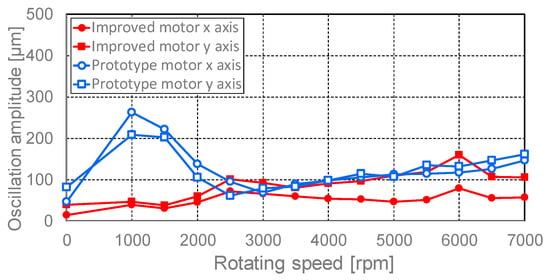
Figure 13.
Maximum oscillation amplitude of the levitated rotor in radial direction with respect to increase in the rotating speed.
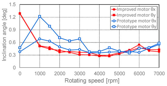
Figure 14.
Maximum inclination angle of the levitated and rotated rotor around x and y axes with respect to increase in the rotating speed.
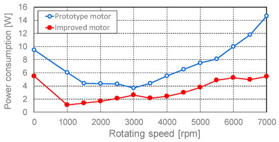
Figure 15.
Power consumption of the developed maglev motor with respect to the increase in the rotating speed.
4. Discussion
Impeller suspension technique using magnetic suspension much contributes to enhance device durability and blood compatibility of the rotary MCS devices. In an ultra-compact maglev motor, optimization of the magnetic circuit for suspension system plays a significant role in the next generation rotary pediatric VADs development.
The lower negative stiffness of the magnetic system can be effective to reduce the suspension index, whereas the decreased stiffness will cause the deterioration of the passive stability in rotor radial direction and the motor torque. The negative stiffness was strategically adjusted to be maintained by keeping peak level of the magnetic flux density produced by the rotor permanent magnets in order to avoid the motor deterioration above mentioned in this study. Decrease in the pole surface area, magnetic gap length and permanent magnet thickness successfully played a significant role in enhancement of the magnetic flux density produced by the electromagnet due to increase in the turn numbers of coils and reduction of the magnetic resistance of the magnetic circuit. Magnetic saturation in the rotor iron could not be occurred because the magnetic flux density ratio of the improved motor and the prototype motor almost uniform in arbitrary angle in the air-gap.
The developed maglev motor successfully achieves the much higher suspension force coefficient ki maintaining the negative stiffness kz in the axial suspension characteristics. The suspension index of ki/kz = 0.47 mm/A is significantly higher than that of the previously developed motor (ki/kz = 0.27 mm/A). The axial negative stiffness was lower than estimated result. One of the causes of the above may have been deteriorated permanent magnet flux caused by reduced magnet volume due to coating thickness. Although the radial suspension characteristics slightly decreased, the deterioration of the total magnetic suspension performance will not occur because the magnitude of the radial suspension force is absolutely small. Even the radial suspension force produced by the newly developed motor is much effective to suppress the resonance and disturbance. The grossly increased inclination torque and the rotating torque due to the increase in the control magnetic flux density will contribute to achieve better suspension stability and low energy consumption.
The axial and radial oscillation amplitude and the inclination angle of the levitated rotor were small enough for rotary blood pump operation to prevent blood trauma. The improved motor demonstrated better magnetic suspension performance with the lower PID control gains than that of the previously developed prototype motor, that is indicating efficacy of the magnetic circuit design refinement to achieve higher mechanical reliability and lower energy input. First, resonance around 50 Hz, which is calculated from the measured radial stiffness and mass of the rotor implies that the resonance will not influence actual pump operation due to lower frequency than the operational frequency of the pediatric pump. The oscillation of the impeller was well suppressed, and resonance peak was not found at any rotating speed. Safeness against the resonance was experimentally verified. Frequency response measurement in all actively controlled axes should be required to investigate advanced dynamic characteristics as a next step.
The power consumption at the operating speed range (4000–5500 rpm) of the pediatric VAD was 2.4–4.9 W. The improved motor with modified magnetic circuit achieved more than 50% reduction of the power consumption compare with that of the previously developed motor. The decreased power consumption should be small enough for pediatric pump operation. The input power increased as increase in the rotating speed. This is due to increase in the copper loss caused by increased suspension current at higher speed rotation and the iron loss. Material change of the stator magnetic core will effectively reduce power consumption at higher rotating speed. In actual pump operation, required rotating torque increases to produce hydraulic output. In contrast, power consumption for suspension may become smaller due to reduced rotor oscillation by higher viscus damping of blood. The blood is filled in the pump cavity, however, magnetic properties of the blood do not affect to the magnetic performance of the self-bearing motor. Total energy input will be evaluated during circulation in future.
5. Conclusions
The ultra-compact 5-DOF-controlled self-bearing motor has been developed for pediatric MCS devices. Shortened magnetic gap and PM thickness effectively increased the control magnetic flux density due to the reduction of magnetic resistance maintaining PM magnetic flux density. In addition, increase in the turn number of the control windings almost double also played a significant role in enhancement of the control flux density production. As a result, the static magnetic suspension characteristics were successfully increased by up to 34–84% by refining the magnetic circuit of the motor. The dynamic magnetic suspension performance and further stable magnetic suspension with high speed rotation is successfully indicated due to the improved force and torque capacity with respect to the excitation current. Energy input was drastically reduced by less than half (1–5 W) because of the reduction of copper loss with low input current. The results indicate the efficacy of the magnetic circuit refinement of the proposed 5-DOF-controlled self-bearing motor. As a next step, dynamic suspension characteristics during pumping in actual circulation condition and pump performance of pediatric rotary VAD will be investigated.
Author Contributions
M.O. wrote the paper; T.M. and E.T. contributed in designing the experimental devices; M.O. performed 3D FEM analysis; M.O. and R.O. conducted the experiments; M.O. analyzed the numeric simulation and experimental results.
Funding
This work was supported by Japanese Society for the Promotion of Science (JSPS) KAKENHI Grant-in-Aid for Young Scientists (B) Grant Number 16K18036.
Conflicts of Interest
The authors declare no conflicts. The funders had no role in the design of the study; in the collection, analyses, or interpretation of data; in the writing of the manuscript, or in the decision to publish the results.
References
- Baldwin, J.T.; Borovetz, H.S.; Duncan, B.W.; Gartner, M.J.; Jarvik, R.K.; Weiss, W.J.; Hoke, T.R. The National Heart, Lung, and Blood Institute Pediatric Circulatory Support. Circulation 2006, 113, 147–155. [Google Scholar] [CrossRef] [PubMed]
- Baldwin, J.T.; Borovetz, H.S.; Duncan, B.W.; Gartner, M.J.; Jarvik, R.K.; Weiss, W.J. The National, Heart, Lung, and Blood Instituted Pediatric Circulatolory Support Program: A Summary of the 5-year Experience. Circulation 2011, 123, 1233–1240. [Google Scholar] [CrossRef] [PubMed]
- Miera, O.; Schmitt, K.R.; Delmo-Walter, E.; Ovroutski, S.; Hetzer, R.; Berger, F. Pump size of Berlin Heart EXCOR pediatric device influences clinical outcome in children. J. Heart Lung Trans. 2014, 33, 816–821. [Google Scholar] [CrossRef] [PubMed]
- Lorts, A.; Zafar, F.; Adachi, I.; Morales, D.L. Mechanical Assist Devices in Neonates and Infants. Semin. Thoracic Cardiovasc. Surg. Pediatric Cardiac Surg. Annu. 2014, 17, 91–95. [Google Scholar] [CrossRef]
- Gibber, M.; Wu, Z.J.; Chang, W.B.; Bianchi, G.; Hu, J.; Garcia, J.; Jarvik, R.; Griffith, B.P. In Vivo Experience of the Child-Size Pediatric Jarvik 2000 Heart: Update. Asaio J. 2010, 56, 369–376. [Google Scholar] [CrossRef]
- Wei, X.; Li, T.; Li, S.; Son, H.S.; Sanchez, P.; Niu, S.; Watkins, A.C.; DeFilippi, C.; Jarvik, R.; Wu, Z.J.; et al. Pre-clinical evaluation of the infant Jarvik 2000 heart in a neonate piglet model. J. Heart Lung Trans. 2013, 32, 112–119. [Google Scholar] [CrossRef][Green Version]
- Baldwin, J.T.; Adachi, I.; Teal, J.; Almond, C.A.; Jaquiss, R.D.; Massicotte, M.P.; Dasse, K.; Siami, F.S.; Zak, V.; Kaltman, J.R.; et al. Closing in on the PumpKIN Trial of the Jarvik 2015 Ventricular Assist Device. Semin. Thoracic Cardiovasc. Surg. Pediatric Cardiac Surg. Annu. 2017, 20, 9–15. [Google Scholar] [CrossRef] [PubMed]
- Allaire, P.E.; Kim, H.C.; Maslen, E.H.; Olsen, D.B.; Bearnson, G.B. Prototype Continuous Flow Ventricular Assist Device Supported on Magnetic Bearings. Artif. Organs 1996, 20, 582–590. [Google Scholar] [CrossRef] [PubMed]
- Allaire, P.; Hilton, E.; Baloh, M.; Maslen, E.; Bearnson, G.; Noh, D.; Khanwilkar, P.; Olsen, D. Performance of a Continuous Flow Ventricular Assist Device: Magnetic Bearing Design, Construction, and Testing. Artif. Organs 1998, 22, 475–480. [Google Scholar] [CrossRef]
- Locke, D.H.; Swanson, E.S.; Walton, J.F.; Willis, J.P.; Heshmat, H. Testing of a centrifugal blood pump with a high efficiency hybrid magnetic bearing. Asaio J. 2003, 49, 737–743. [Google Scholar] [CrossRef]
- Merkel, T. Magnetic Bearing in INCOR Axial Blood Pump Acts as Multifunctional Sensor. In Proceedings of Ninth International Symposium on Magnetic Bearings; University of Kentucky Department of Mechanical Engineering: Lexington, KY, USA, 2004. [Google Scholar]
- Wearden, P.D.; Morell, V.O.; Keller, B.B.; Webber, S.A.; Borovetz, H.S.; Badylak, S.F.; Boston, J.R.; Kormos, R.L.; Kameneva, M.V.; Simaan, M.; et al. The PediaFlow Pediatric Ventricular Assist Device. Semin. Thoracic Cardiovasc. Surg. Pediatric Cardiac Surg. Annu. 2006, 9, 92–98. [Google Scholar] [CrossRef] [PubMed]
- Yumoto, A.; Shinshi, T.; Zhang, X.; Tachikawa, H.; Shimokohbe, A. A One-DOF-controlled Magnetic Bearing for Compact Centrifugal Blood Pumps, Motion and Vibration Control; Springer: Dordrecht, Netherlands, 2009. [Google Scholar]
- Nguyen, Q.D.; Ueno, S. Analysis and Control of Nonsalient Permanent Magnet Axial Gap Self-Bearing Motor. IEEE Trans. Ind. Electron. 2011, 58, 2644–2652. [Google Scholar] [CrossRef]
- Asama, J.; Hamasaki, Y.; Oiwa, T.; Chiba, A. Proposal and Analysis of a Novel Single-Drive Bearingless Motor. IEEE Trans. Ind. Electron. 2013, 60, 129–138. [Google Scholar] [CrossRef]
- Takeda, R.; Ueno, S.; Jiang, C. Development of a Centrifugal Cryogenic Fluid Pump using an Axial Self-bearing Motor. In Proceedings of the 15th International Symposium on Magnetic Bearings, Kitakyushu, Japan, 3–6 August 2016. [Google Scholar]
- Nojiri, C.; Kijima, T.; Maekawa, J.; Horiuchi, K.; Kido, T.; Sugiyama, T.; Mori, T.; Sugiura, N.; Asada, T.; Umemura, W.; et al. Development Status of Terumo Implantable Left Ventricular Assist System. Artif. Organs 2001, 25, 411–413. [Google Scholar] [CrossRef] [PubMed]
- Maher, T.R.; Butler, K.C.; Poirier, V.L.; Gernes, D.B. HeartMate Left Ventricular Assist Devices: A Multigeneration of Implanted Blood Pumps. Artif. Organs 2001, 25, 422–426. [Google Scholar] [CrossRef]
- Hoshi, H.; Shinshi, T.; Takatani, S. Third-generation Blood Pumps with Mechanical Noncontact Magnetic Bearings. Artif. Organs 2006, 30, 324–328. [Google Scholar] [CrossRef]
- Farrar, D.J.; Bourque, K.; Dague, C.P.; Cotter, C.J.; Poirier, V.L. Design Features, Developmental Status, and Experimental Results with the Heartmate III Centrifugal Left Ventricular Assist System With a Magnetically Levitated Rotor. Asaio J. 2007, 53, 310–315. [Google Scholar] [CrossRef] [PubMed]
- Timms, D.L.; Kurita, N.; Greatrex, N.; Masuzawa, T. BiVACOR A Magnetically Levitated Biventricualr Artificial Heart. In Proceedings of the 20th MAGDA conference in Pacific Asia, Kaohsiung, Taiwan, 14–16 November 2011. [Google Scholar]
- Mehra, M.R.; Naka, Y.; Uriel, N.; Goldstein, D.J.; Cleveland Jr, J.C.; Colombo, P.C.; Walsh, M.N.; Milano, C.A.; Patel, C.B.; Jorde, U.P.; et al. A Fully Magnetically Levitated Circulatory Pump for Advanced Heart Failure. N. Engl. J. Med. 2017, 376, 440–450. [Google Scholar] [CrossRef] [PubMed]
- Osa, M.; Masuzawa, T.; Tatsumi, E. Miniaturized axial gap maglev motor with vector control for pediatric artificial heart. J. JSAEM 2012, 20, 397–403. [Google Scholar]
- Kurita, N.; Ishikawa, T.; Saito, N.; Masuzawa, T. Basic Design of the Maglev Pump for Total Artificial Heart by using Double Stator Type Axial Self-bearing Motor. In Proceedings of the 15th International Symposium on Magnetic Bearings, Kitakyushu, Japan, 3–6 August 2016. [Google Scholar]
- Osa, M.; Masuzawa, T.; Tatsumi, E. 5-DOF Control Double Stator Motor for Paediatric Ventricular Assist Device. In Proceedings of ISMB13; University of Virginia: Charlottesville, VA, USA, 2012. [Google Scholar]
- Osa, M.; Masuzawa, T.; Omori, N.; Tatsumi, E. Radial position active control of double stator axial gap self-bearing motor for pediatric VAD. Mech. Eng. J. 2015, 2, 15-00105. [Google Scholar] [CrossRef]
- Osa, M.; Masuzawa, T.; Saito, T.; Tatsumi, E. Miniaturizing 5-DOF fully controlled axial gap maglev motor for pediatric ventricular assist devices. Int. J. Appl. Electromagnet Mech. 2016, 52, 191–198. [Google Scholar] [CrossRef]
- Osa, M.; Masuzawa, T.; Orihara, R.; Tatsumi, E. Magnetic suspension performance enhancement of ultra-compact 5-DOF-controlled self-bearing motor for rotary pediatric ventricular assist device. In Proceedings of the 11th International Symposium on Linear Drives for Industry Applications (LDIA), Osaka, Japan, 6–8 September 2017. [Google Scholar]
© 2019 by the authors. Licensee MDPI, Basel, Switzerland. This article is an open access article distributed under the terms and conditions of the Creative Commons Attribution (CC BY) license (http://creativecommons.org/licenses/by/4.0/).