Article

Finite Element Model of Vibration Control for an Exponential Functionally Graded Timoshenko Beam with Distributed Piezoelectric Sensor/Actuator

1
Laboratory of Advanced Materials Studies and Applications, FS-EST, Moulay Ismail University, Meknes 50000, Morocco
2
National School of Applied Sciences, Mohammed Premier University, Oujda 60050, Morocco
3
National School of Applied Sciences, Abdelmalek Essaadi University, Tétouan 93030, Morocco
*
Author to whom correspondence should be addressed.
Actuators 2019, 8(1), 19; https://doi.org/10.3390/act8010019
Submission received: 26 December 2018 / Revised: 18 February 2019 / Accepted: 21 February 2019 / Published: 26 February 2019

Abstract

:
This paper presents a dynamic study of sandwich functionally graded beam with piezoelectric layers that are used as sensors and actuators. This study is exploited later in the formulation of the active control laws, while using the optimal control Linear Quadratic Gaussian (LQG), accompanied by the Kalman filter. The mathematical formulation is based on Timoshenko’s assumptions and the finite element method, which is applied to a flexible beam divided into a finite number of elements. By applying the Hamilton principle, the equations of motion are obtained. The vibration frequencies are found by solving the eigenvalue problem. The structure is analytically then numerically modeled and the results of the simulations are presented in order to visualize the states of their dynamics without and with active control.

1. Introduction

In the mid-1980s, a group of Japanese scientists introduced, for the first time, a new class of composites, called Functional Graded Materials (FGM) [1]. In a Functional Graded (FG) material, the composition and also the structure gradually change over the volume, which causes corresponding changes in the properties of the material [2]. As ultra-high temperature resistant materials, these types of composites are well known and widely used in many engineering applications. For example, the FGMs are in the fields of aeronautics, nuclear, marine engineering, and biomedical equipment [3]. In recent years, there has been a growing interest in the application of FGMs in mechanical structures, especially those that are working in extreme thermal conditions [4]. The analysis of composite structures is exploited with the advanced numerical methods, particularly the finite element method. Due to the wide application of the FGM, several studies have been carried out on the mechanical [5] and thermal behavior of these materials [6,7]. In addition, structural vibrations and environmental conditions are physical phenomena that act on structures during their life cycle. To protect structures against undesired vibrations, several techniques are used, such as active, passive, or hybrid vibration control due to external excitation. The techniques that were used in passive control consist in using absorbent materials [8]. For wide frequency range excitation, vibration’s damping, like viscous, coulomb, and hysteresis damping. Another technique is to avoid resonance by modifying the mass and rigidity to avoid the coincidence of natural frequencies. The active control techniques means adding some actuators in the controlled object structure and adjusting the output of the actuator by the control algorithm, so that the output of the actuator and the vibration of the controlled device are offset, so as to achieve the purpose of reducing vibration. An active vibration control system mainly consists of sensors, controllers, and actuators [9]. Among these sensors and actuators that were using in this technique, there are piezoelectric materials.
The piezoelectric effect corresponds to a first order linear electroelastic coupling. The term electromechanical interaction in the total energy expression involves the relation between the mechanical and electrical quantities. There are several researches, in which piezoelectric materials are used to reduce vibrations, such as the energy method, the deformation shear theory, and the finite element method [10,11,12,13].
Extensive theoretical and experimental studies have been carried out and published on FGM structures and the beams have always remained of interest to researchers due to their applications. Elshafei et al. [14] have developed a finite element formulation for the modeling and analysis of isotropic and orthotropic composite beams with piezoelectric actuators. Ferdek et al. [15] presented the results of the simulation of the active reduction of beam’s vibration in FGM materials by piezoelectric actuators. Sanbi et al. [10] have studied the thermoelastic and piezoelectric coupling effects on dynamics and active control of piezolaminated intelligent beam that is modeled by the finite element method. Bendine et al. [11] reported a study of active vibration control of functionally graded beams with piezoelectric top and bottom layers. El Harti et al. [12] studied the active vibration control of a FGM sandwich beam with piezoelectric sensor/actuator with new geometry. Panda et al. [13] studied the active vibration control of smart functionally graded beams. Bodaghi et al. [16] presented a study regarding the nonlinear active control of FG beams in thermal environments that were subjected to blast loads with integrated FGP sensor/actuator layers. Allahverdizadeh et al. [17] worked on the vibratory behavior of functionally graded electrorheological sandwich beams. Gharib et al. [18] developed an analytical solution for the analysis of functionally graded material (FGM) beams containing integrated layers of piezoelectric material that acts as sensor and actuator, based on the first-order shear deformation theory. Ebrahimi et al. [19] presented a thermo-mechanical vibration behavior of non-uniform beams that were made of functionally graded (FG) porous material, under different thermal loadings. Narayanan et al. [20] presented a finite element modeling of piezolaminated smart structures for active vibration control with distributed sensors and actuators. Kargarnovin et al. [21] studied the active vibration control of functionally graded plates using piezoelectric patches. Jadhav et al. [22] analyzed the free and forced vibrations of functionally graded plate. Rahmoune et al. [23] worked on the dynamics and shape control of vibrating composite plates containing piezoelectric laminas. Zhu et al. [24] presented an evaluation of the shear piezoelectric coefficient d15 of piezoelectric ceramics by using a piezoelectric cantilever beam in dynamic resonance.
The objective of this work is the analysis of the structural dynamics of a FGM sandwich beam with Timoshenko’s assumptions and the finite element method. Subsequently, the active vibrations control the FG beam, with piezoelectric materials being using as sensors and actuators. The fact of using two pairs of piezoelectric materials that are symmetrically bonded with respect to the neutral axis is to eliminate the membrane effect, in the sense that the pairs sensor or actuators react in the same way, but in the opposite direction. The control method that is presented above is the so-called LQR (Linear Quadratic Regulator) control. This type of regulator thus presupposes a perfect knowledge of all the state variables. In practice, the observation of the state variables is incomplete and is often corrupted by Gaussian type measurement noise. Nevertheless, one can estimate the unmeasured states by Kalman filtering. As it is assumed that these noises are of Gaussian type, from which comes linear quadratic Gaussian control (LQG). Many types of disturbances are applied in this study; impulse, step, and white noise, and the comparison between controlled and uncontrolled responses is shown.

2. Mathematical Modeling

Consider a beam of length L in the x-direction, of rectangular section with the width b in the y-direction and the thickness h in the z-direction, as shown in Figure 1. The beam consists of a functionally graded material composed of metal and ceramic, partially covered by four piezoelectric, actuators, and sensors, which are bonded to the upper and lower faces of the FGM core [25].
The structure presents symmetry both geometric and material with respect to its neutral plane, where there is a decoupling between traction and bending. The curvature of the beam only produces a bending moment [26,27].
Many researchers use the exponential function to describe the material properties of FGM, and the exponential function E-FGM is given as [28]:
E ( z ) = Ae β ( z + h / 2 ) ,
with
A = E 1 ,   β = 1 h ln ( E 1 E 2 ) ,
where E 1 and E 2 , respectively, illustrate the material properties (Young’s modulus, density, or Poisson’s ratio) of the lower surface z = h / 2 and the upper surface z = + h / 2 of the E-FGM beam.
The variation of the Young’s modulus through the thickness of the E-FGM beam is shown in Figure 2.
According to the theory of Timoshenko, the longitudinal and transverse displacements are written, respectively [29]:
u ( x , y , z , t ) = z θ ( x , t ) , w ( x , y , z , t ) = w ( x , t ) ,
The nonzero components of strain can be written as [30]:
ε xx = z θ x , γ xz = w x + θ ,
The strain energy U of the element can be written as:
U = 1 2 0 l A { σ } T { ε } dAdx ,
where l is the element’s length. Equation (5) could be finally reformulated as:
U = 1 2 0 l [ θ x w x + θ ] T [ EI 0 0 KGA ] [ θ x w x + θ ] dx ,
where E, G, and I are, respectively, Young modulus, shear modulus, and the area moment of inertia of the cross-section, and K = 10 ( 1 + ν ) / ( 12 + 11 ν ) being the shear coefficient [31].
The kinetic energy of the element is given as:
T = 1 2 0 l A ρ { ( u t ) 2 + ( v t ) 2 + ( w t ) 2 } dAdx ,
Equation (7) could be reformulated as:
T = 1 2 0 l [ w t θ t ] T [ ρ A 0 0 ρ I ] [ w t θ t ] dx ,
where ρ is the mass density. The total work W e , due to the external forces in the beam, is given by:
W e = 0 l [ w θ ] T [ q d m ] dx ,
where q d and m represent, respectively, the distributed force and the moment throughout the beam element. The equations of motion are derived via the Hamilton’s principle:
δ = t 1 t 2 ( δ U δ T δ W e ) dt = 0 ,
with δ U , δ T , and δ W e represent the variations of strain energy, kinetic energy, and the work of external forces, respectively.
By substituting the values of the energies in the last equation and integrating by parts, we obtain the differential equations of general shape of a beam that is modeled by the Timoshenko theory, shown as:
{ KGA ( w x + θ ) } x + q d = ρ A 2 w t 2 ,
{ EI θ x } x KGA ( w x + θ ) + m = ρ I 2 θ t 2 ,
In the static case, without external forces acting on the beam, the equations of motion are reduced, as follows:
{ KGA ( w x + θ ) } x = 0 ,
{ EI θ x } x KGA ( w x + θ ) = 0 ,

3. Finite Element Formulation

The equations governing the beam based on the Timoshenko theory could be satisfied if their polynomial order in w is far greater by one order of θ [29]. As there are four degrees of freedom DOF for a beam element [25,32,33,34], the transversal displacement is approached by a cubic polynomial whereas θ is approached by a quadratic polynomial. Using the boundary conditions for the embedded-free beam, the transversal displacement w ( x , t ) and its first and second spatial derivatives are given in matrix form as:
w ( x , t ) [ N w ] [ q ] , w ˙ ( x , t ) [ N θ ] [ q ] , w ¨ ( x , t ) [ N a ] [ q ] ,
with
q = [ w 1 θ 1 w 2 θ 2 ] T ,
where q ˙ is its time derivative, [ N w ] T , [ N θ ] T , and [ N a ] T are respectively, the shape functions for displacements, rotations, and accelerations [29,35,36].
Substituting the shape functions in the Hamilton principle, then integrating over the entire length of the element develops the equation of motion’s element:
M q ¨ + Kq = f ,
where the elementary mass matrices of the piezoelectric and FGM elements are expressed, respectively, as:
[ M p ] = 1 2 0 l p [ N w N θ ] T [ ρ p A p 0 0 ρ p I p ] [ N w N θ ] dx ,
[ M FGM ] = 1 2 0 l b [ N w N θ ] T [ C 1 0 0 C 2 ] [ N w N θ ] dx ,
and the elementary stiffness matrices of the piezoelectric and FGM elements are also expressed, respectively, as:
[ K p ] = 1 2 0 l p [ N θ x N w x + N θ ] T [ E p I p 0 0 KG p A p ] [ N θ x N w x + N θ ] dx ,
[ K FGM ] = 1 2 0 l b [ N θ x N w x + N θ ] T [ C 3 0 0 C 4 ] [ N θ x N w x + N θ ] dx ,
with C 1 , C 2 , C 3 , and C 4 are constants that depend on the characteristics of the FGM material, given as:
C 1 = b 0 h ρ ( z ) dz , C 2 = b 0 h ρ ( z ) z 2 dz , C 3 = b 0 h E ( z ) z 2 dz , C 4 = b 0 h KG ( z ) dz ,
The local elementary matrices of mass and stiffness of the piezo-FGM-piezo (FGM covered by piezoelectric layers) are illustrated in the following formula:
[ M pF ] = [ M FGM ] + 2 [ M p ] , [ K pF ] = [ K FGM ] + 2 [ K p ] ,

4. Sensor/Actuator Equations

The linear piezoelectric coupling between the elastic field and the electric field can be expressed by the direct and inverse piezoelectric constitutive Equation [37,38], as:
D z = d 31 σ + e σ E f , D z = d 31 E f + S e σ ,
where D z is the electric displacement, d 31 is the piezoelectric constant, σ is the stress, e is the permittivity of the medium (dielectric constant), E f is the electric field, ε is the strain, and S E is the compliance of the piezoelectric medium.
The sensor equation is derived from the direct piezoelectric equation, which is used to calculate the total load by the strain in the structure.
Since no external field is applied to the sensor layer, the electrical displacement that was developed on the sensor surface is directly proportional to the strain acting on it. If the polarization is carried out along the thickness direction of the sensors with the electrodes on the upper and lower surfaces, the electric displacement is given as:
D z ε x = e 31 ε x ,
The total load Q developed on the sensor surface is the spatial summation of all the point charges that developed on the sensor layer, and it is given as:
Q ( t ) = A D z dA ,
i ( t ) = dQ ( t ) dt = d dt A e 31 ε x dA ,
Since the strain ε x of the structure can be expressed in terms of the second spatial derivative of displacement w ¨ ( x , t ) as   ε x = z d 2 w dx 2 , where z is the coordinate of a point on the beam (neutral axis), the equation can be written as:
i ( t ) = d dt A e 31 zn 1 T qdA = A e 31 zn 1 T d dt ( q ) dA ,
i ( t ) = e 31 zb 0 l p n 1 T q ˙ dx ,
The voltage will be applied as an input to the actuator with an accurate gain depending on the degree of damping desired.
V c ( t ) = G c e 31 zb 0 l p n 1 T q ˙ dx ,
where   z = ( h 2 + t s ) , and e 31 being the piezoelectric stress/load constant.
V 1 c ( t ) = S c [ 0 1 0 1 ] ,
V 2 c ( t ) = S c [ 0 1 0 1 ] ,
where S s = G C e 31 z 1 b is called the sensor constant.
The last equations of the two sensors can be written in the form below:
V 1 s ( t ) = V 2 s ( t ) = p T q ˙ ,
The control input u is given as:
V a ( t ) = Gain   control × V s ( t ) ,
The resulting moment acting on the element due to the voltage V a is determined by the integration of the stress over the entire beam thickness, which becomes after simplification:
M a = E p d 31 z ¯ V a ( t ) ,
with z ¯ = t a + h 2 being the distance between the symmetry axes of the core and the piezoelectric actuator, E p is the Young’s modulus of piezoelectric material.
The control force f ctr produced by the actuator could be expressed as:
f ctr 1 = hV 1 a ( t ) = hu ( t ) ,
f ctr 2 = hV 2 a ( t ) = hu ( t ) ,
where h is a constant vector which depends on the actuator’s characteristics.
h T = E p d 31 b z ¯ [ 1 0 1 0 ] = a c [ 1 0 1 0 ] ,
and a c = E p d 31 b z ¯ being the actuator’s constant.

5. Dynamic Equation and State Space Model

The equation of motion of the whole structure and the control equation are written, respectively, as:
M q ¨ + Kq = f ext + f ctr 1 + f ctr 2 = f t
y i ( t ) = V i s ( t ) = p i T q ˙ , i = 1 , 2 ,
In order to take interest in the first modes of vibration, generalized coordinates using the transformation q = Tg are introduced into Equations (39) and (40).
Here, T is the modal matrix that contains the vectors representing the desired number of vibration modes of the embedded beam, q is the vector of the generalized coordinates, and g is the principal coordinates.
Equations (39) and (40) turn into the following formula:
MT g ¨ + KTg = f ext + f ctr 1 + f ctr 2 = f t ,
y i ( t ) = V i s ( t ) = p i T q ˙ = p i T T g ˙ ,
Multiplying the Equation (41) by T T , the equation could be reformulated, as follows:
M * g ¨ + K * g = f ext * + f ctr 1 * + f ctr 2 * ,
where M * and K * are called the generalized mass and stiffness matrices.
Using Rayleigh’s proportional damping [39,40]:
C * = α M * + β K * ,
where α and β are, respectively, the friction damping constant and the structural damping constant.
The dynamic equation of the structure and the control equation are finally given by:
M * g ¨ + C * g ˙ + K * g = f ext * + f ctr 1 * + f ctr 2 * ,
The state space model in MIMO mode is given by:
x ˙ = Ax ( t ) + Bu ( t ) + Er ( t ) ,
y ( t ) = C T x ( t ) + Du ( t ) ,
A = [ 0 I M * 1 K * M * 1 C * ] ,   B = [ 0 0 M * 1 T T h 1 M * 1 T T h 2 ] ,   C T = [ 0 p 1 T T 0 p 2 T T ] ,   D = 0 ,   E = [ 0 M * 1 T T f ]
where r(t), u(t), A, B, C, D, E, x(t), and y(t) represent, respectively, the input force, the control input, the system matrix, the input matrix, the output matrix, the transmission matrix, external loads matrix, state vector, and system output.

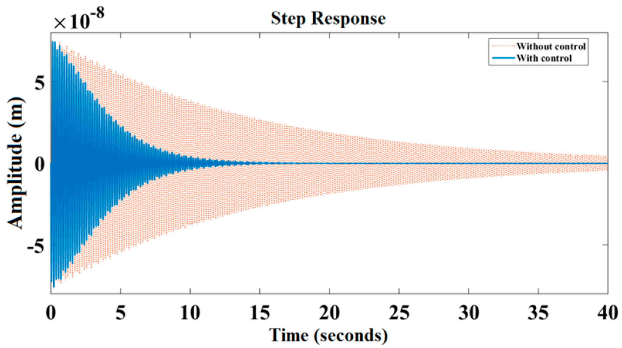
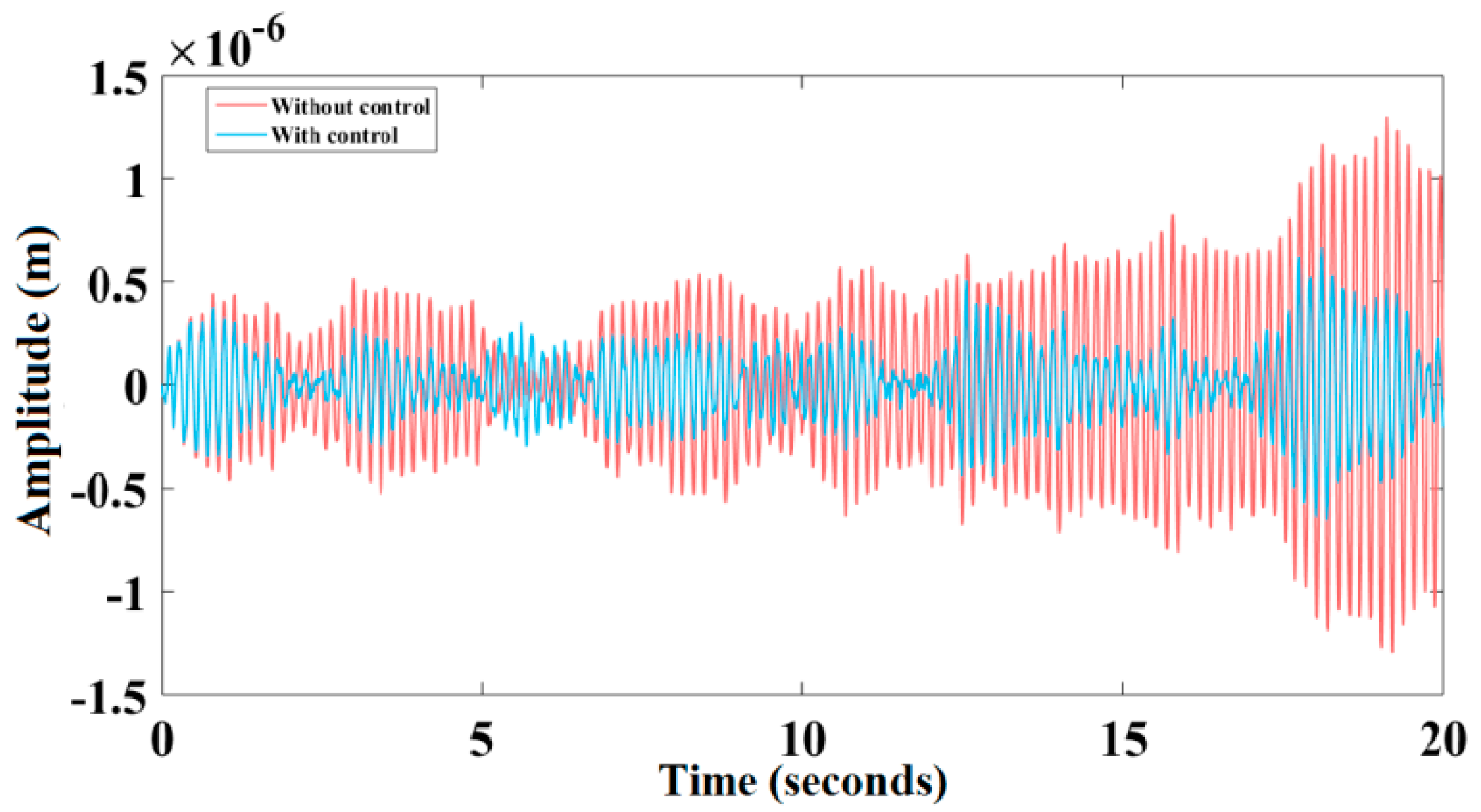
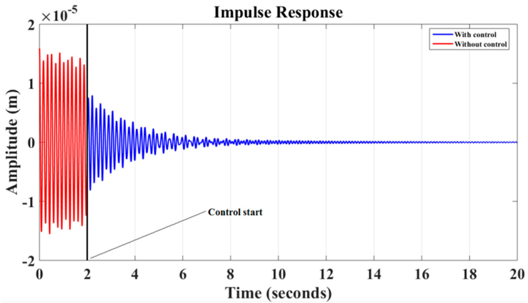
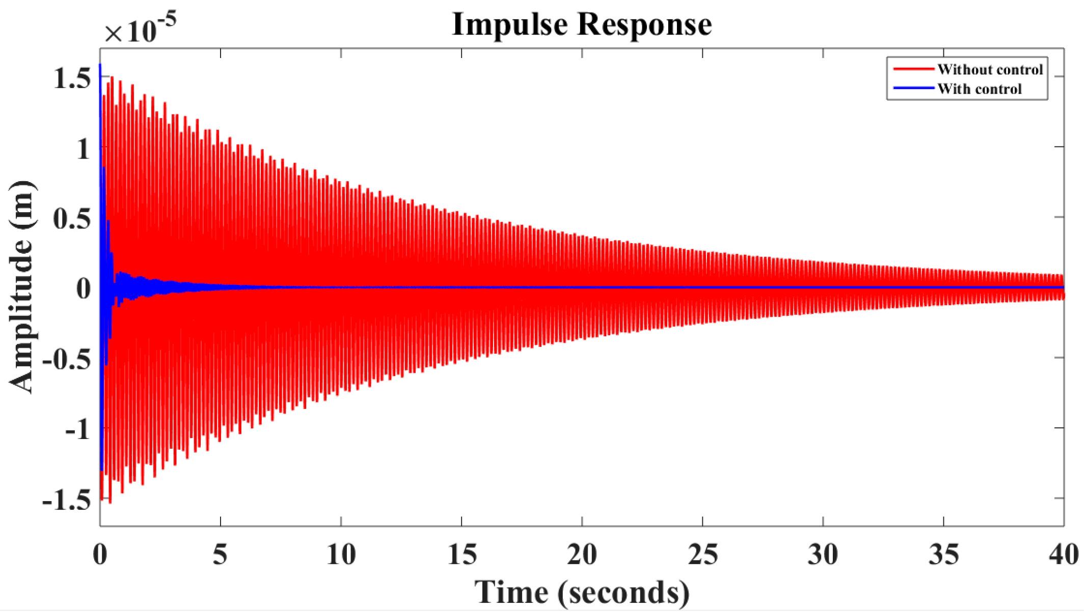
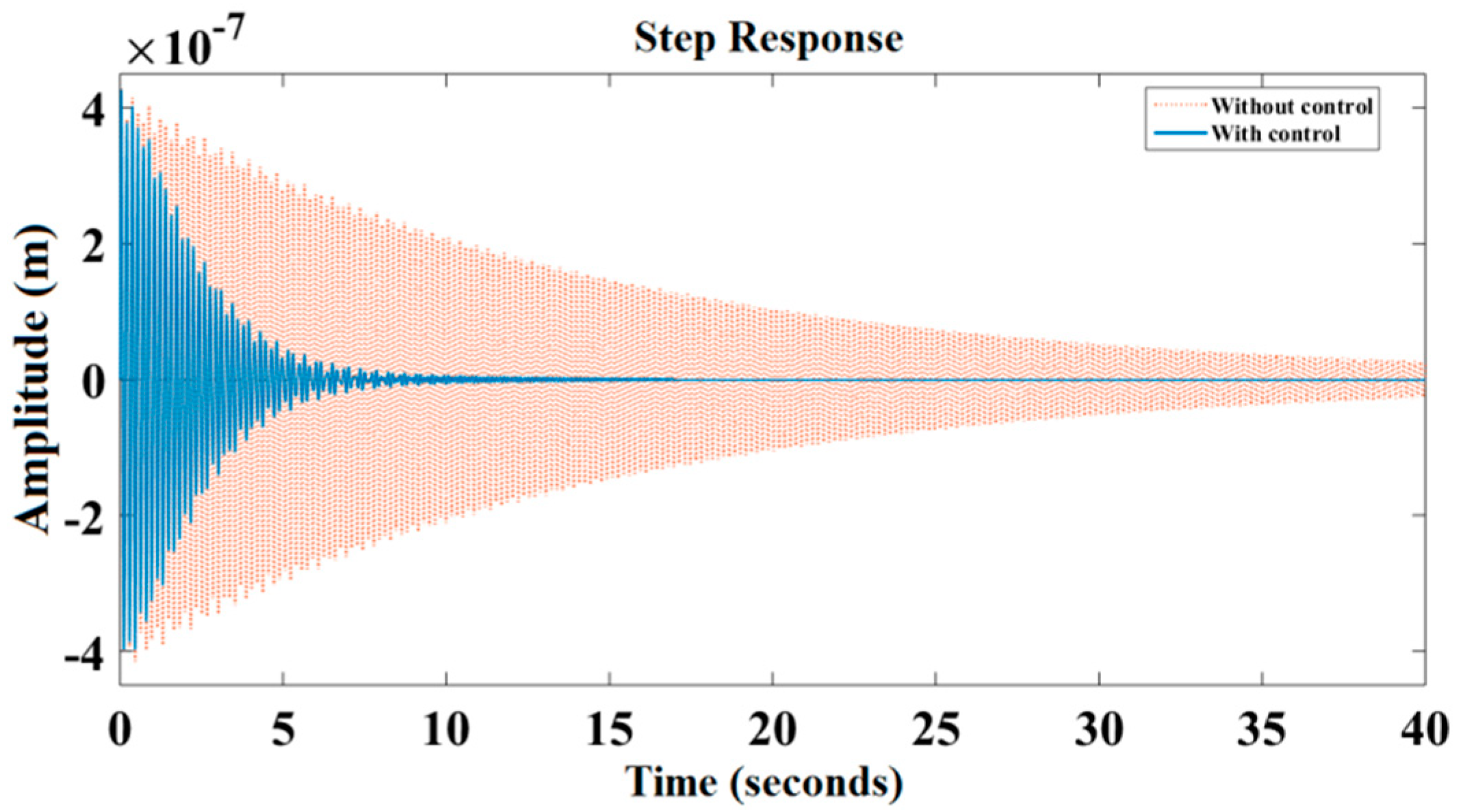
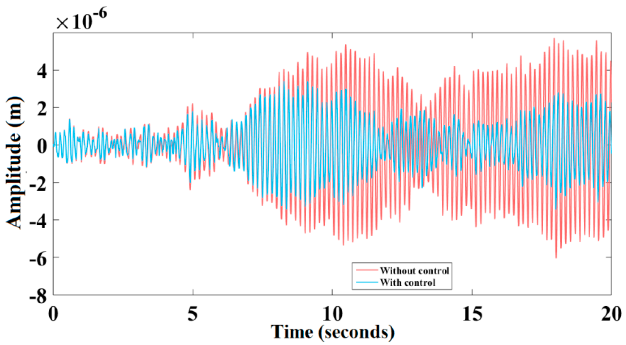
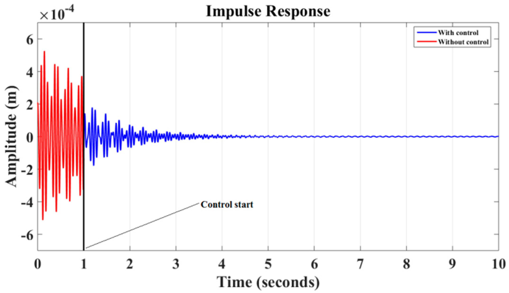
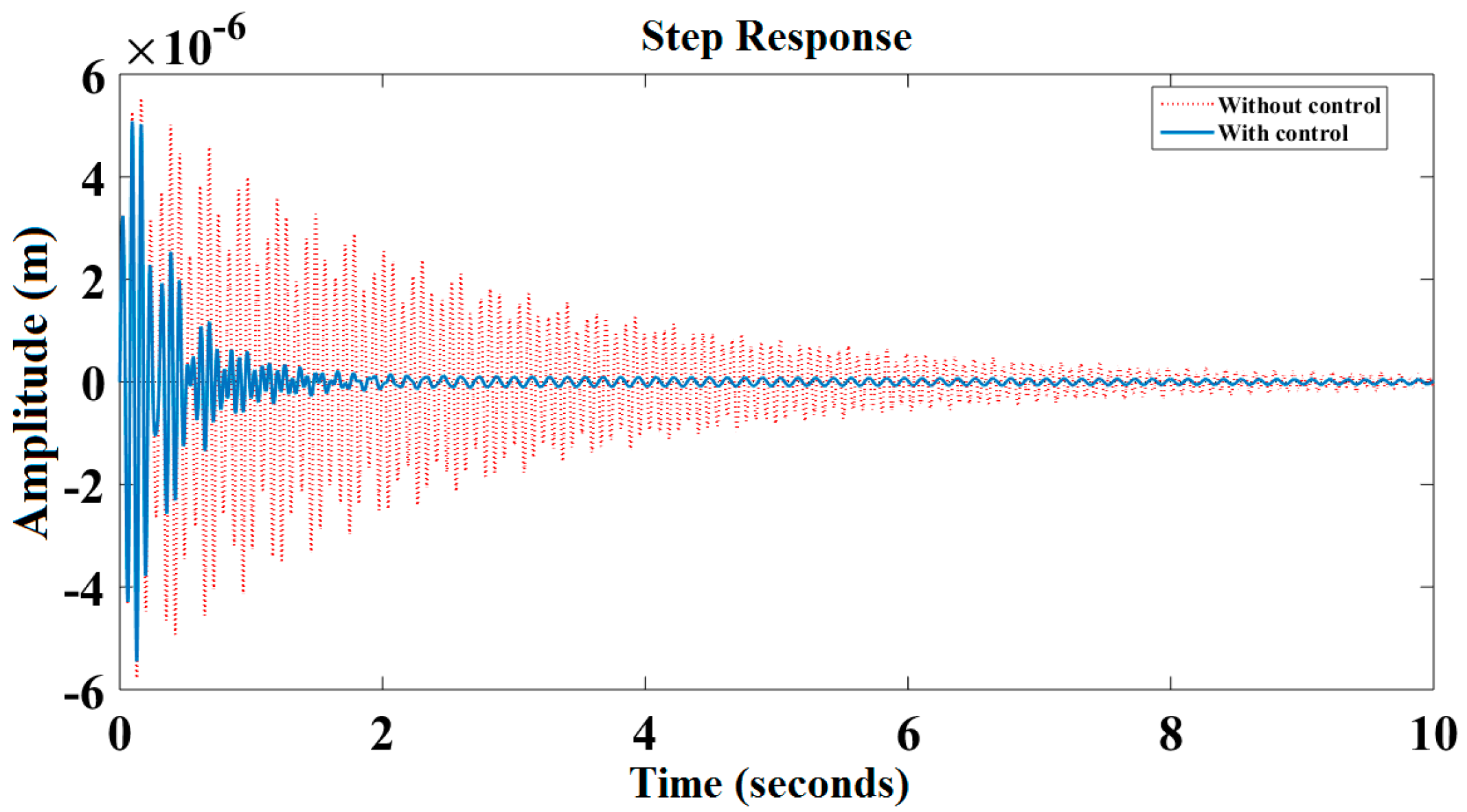
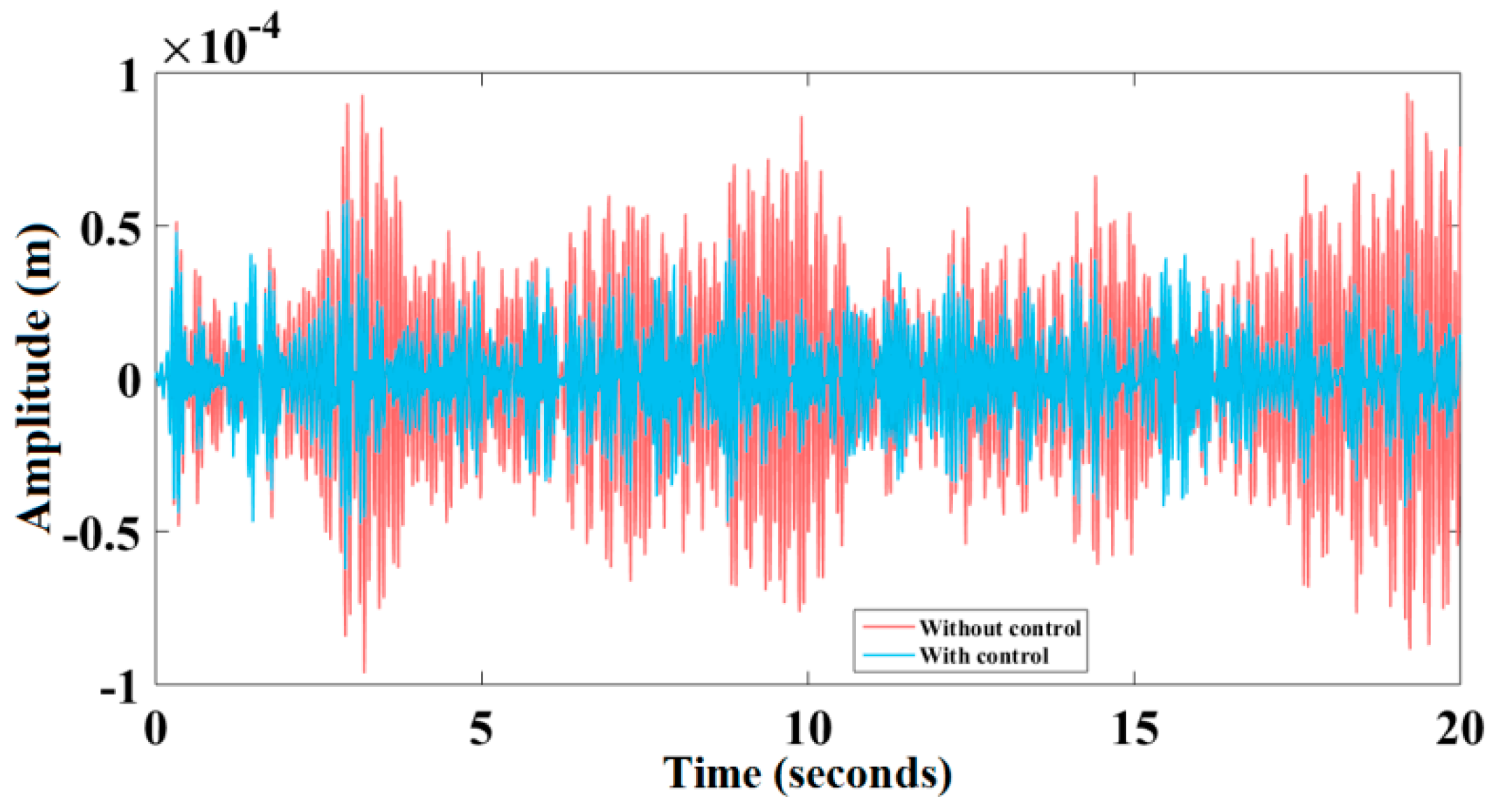
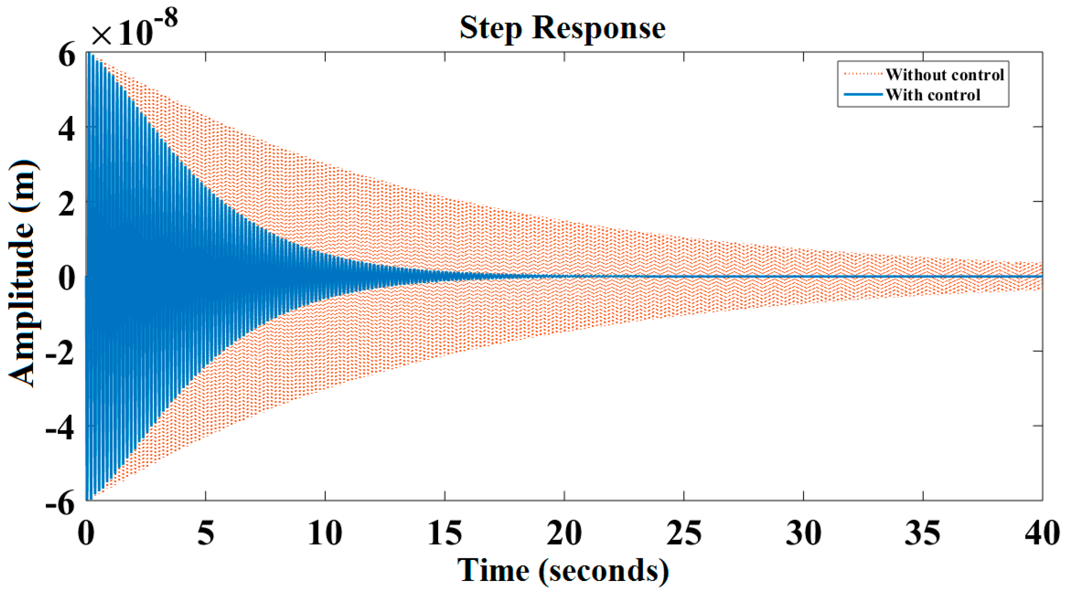
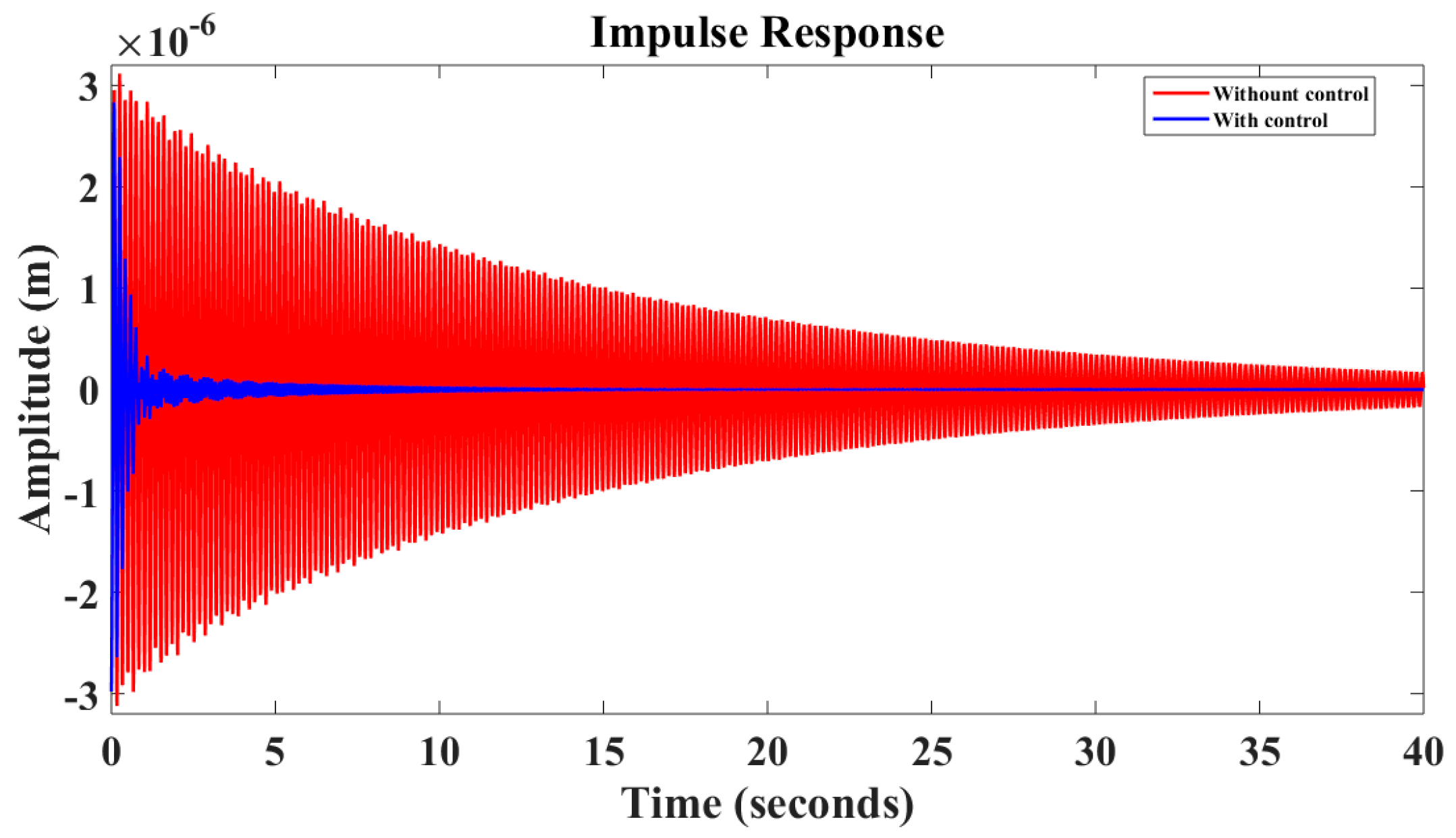
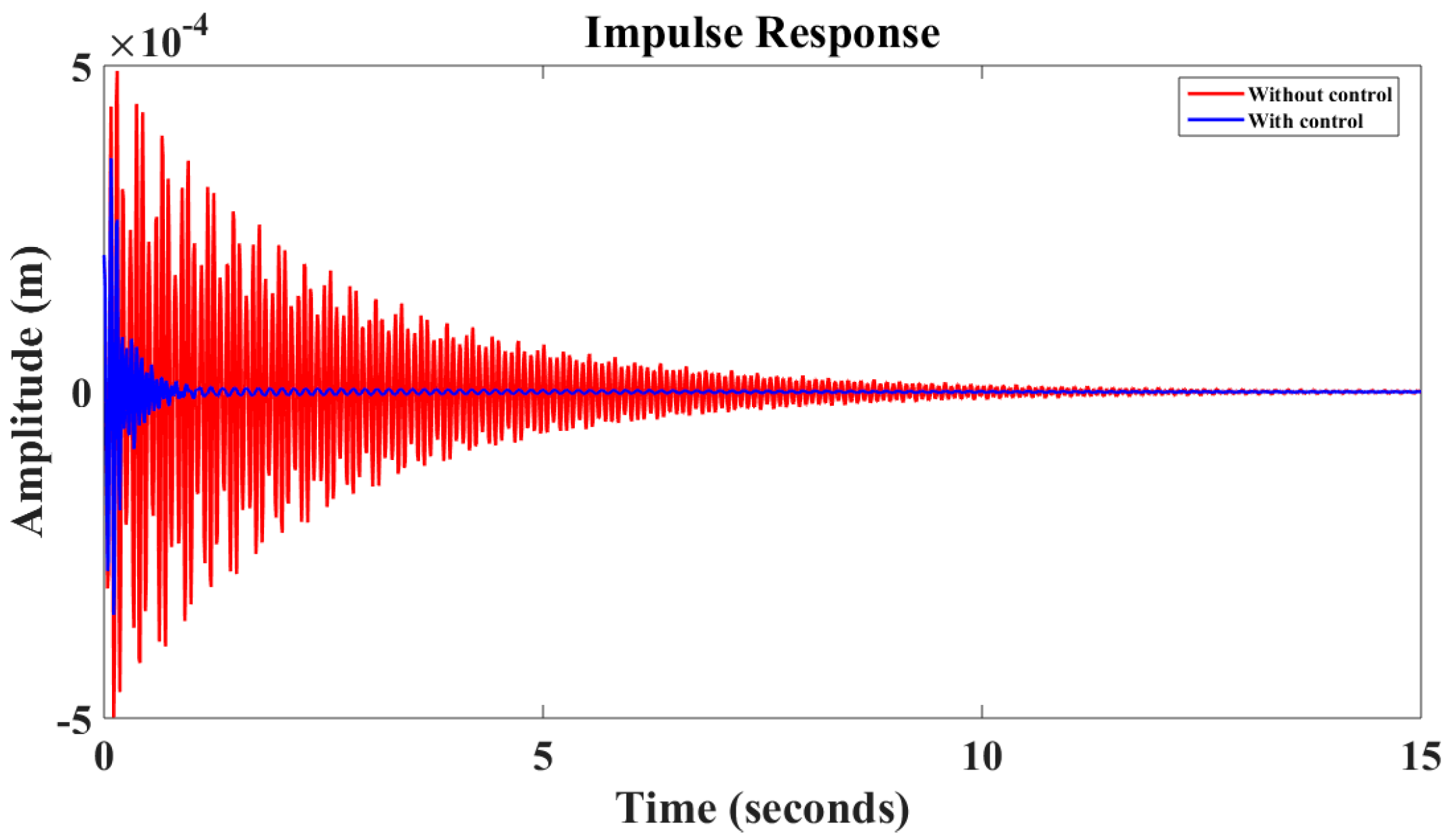
6. Results and Discussion

In order to validate our control procedure, we consider a flexible beam that is embedded at its left end and composed of an E-FGM core, being partially covered by four thin PZT piezoelectric layers. The optimal LQG control and Kalman observer are operated in order to study the influence of the actuator/sensor’s location on the quality control. The geometrical and physical characteristics of the materials are shown in Table 1.
The LQG-Kalman control technique is used to design an estimator in order to eliminate the first three modes of vibration of a flexible embedded beam, from a concept of smart structure for the state space model, an external forces f ext in the form of amplitude impulse disturbances (1N), is applied for a duration of one second at the free end of each considered model of the beam.
The figures that are presented above correspond to the responses of the free end of the beam in which we compare the controlled and uncontrolled responses for Impulse, Step, and White noise disturbances.
Figure 3, Figure 4, Figure 5, Figure 6, Figure 7, Figure 8, Figure 9, Figure 10, Figure 11, Figure 12, Figure 13, Figure 14, Figure 15, Figure 16, Figure 17 and Figure 18 show the impulse, step, and white noise responses of the beam by varying the sensor pair’s location from the finite element 1 to the finite element 4, and keeping the actuator pair in the finite element 5. Figure 3, Figure 7, Figure 11 and Figure 15 show the application of the active control procedure after a duration lengths of (four, two, and one second), against the Figure 4, Figure 8, Figure 12 and Figure 16, show the comparison between the controlled and uncontrolled impulse response of the beam. Figure 5, Figure 9, Figure 13 and Figure 17 present the controlled and uncontrolled step response. Figure 6, Figure 10, Figure 14 and Figure 18 show the controlled and uncontrolled white noise response of the beam, with increasing the weight matrix Q against R = 1 remains constant in all different figures.
It is noted that the variation of the piezoelectric pair’s for E-FGM causes a significant impact on the structural and vibratory behavior of the beam. Additionally, it is observed that, when changing the piezoelectric pair’s location, from the embedded end to the free end, the control time decreases, contrary to the amplitudes of vibrations, which show a significant increase. The figures that are presented before show the quality and the efficiency of the active control technique used.
The experimental setup that is given and illustrated in reference [41] can be used to validate our analytic results. To fulfill the illustration of structural responses in the low frequency scope, the PZT sensors are attached on both sides of the FGM beam. The sensors are chosen to lie near the root of the beam where the strain energy of the structure is the highest. Two PZT actuators are bonded onto both sides of the FGM beam. Moreover, a laser displacement sensor can be used to measure the tip displacement of the beam. An electromagnetic vibrator can be fixed to excite the vibration of the beam as an external disturbance. The real-time control system can be implemented using a personal computer. A data acquisition device can be used for data acquisition and control output. A power amplifier that can amplify the input signals drives the PZT actuator. The strain signal is low-pass filtered and amplified through a strain amplifier, which can amplify the signal to a voltage range. The output signal of the laser displacement sensor is conditioned to a voltage signal by a signal conditioner. In addition, the LabVIEW programming software can develop all of the control algorithms.

7. Conclusions

In this work, we have studied the structural vibrations of a sandwich FGM beam that is covered partially by four piezoelectric thin films. The model was developed using finite element method and Timoshenko’s assumptions, and then its active control via the PZT piezoelectric elements. We have discussed the case in which two pairs of piezoelectric materials were used to eliminate the membrane effect. The results that were exploited in the formulation of active control laws using the optimal control linear quadratic Gaussian LQG and Kalman filtering. Figure 3, Figure 4, Figure 5, Figure 6, Figure 7, Figure 8, Figure 9, Figure 10, Figure 11, Figure 12, Figure 13, Figure 14, Figure 15, Figure 16, Figure 17 and Figure 18 show the influence of changing the piezoelectric sensor pair’s location from the finite element 1 to the finite element 4, on the structure behavior and on the control procedure. In the Figure 3, Figure 7, Figure 11 and Figure 15, the control starts after a duration of (4, 2, and 1 s). Figure 4, Figure 8, Figure 12 and Figure 16 show the comparison between the controlled and uncontrolled impulse response of the beam. Figure 5, Figure 9, Figure 13 and Figure 17 present the controlled and uncontrolled step response, and finally the Figure 6, Figure 10, Figure 14 and Figure 18 show the controlled and uncontrolled white noise response. These different results show the influence of the piezoelectric pair’s location on the structure dynamics, as well as the success of control technique used.

Author Contributions

Formal analysis, M.S.; Methodology, M.B.; Software, M.R.; Validation, R.S.; Writing–original draft, K.E.H.; Writing–review, Supervision & editing, M.R.

Funding

This research received no external funding.

Conflicts of Interest

The authors declare no conflict of interest.

References

  1. Koizumi, M. FGM activities in Japan. Compos. Part B Eng. 1997, 28, 1–4. [Google Scholar] [CrossRef]
  2. Bharti, I.; Gupta, N.; Gupta, K.M. Novel Applications of Functionally Graded Nano, Optoelectronic and Thermoelectric Materials. Int. J. Mater. Mech. Manuf. 2013, 1, 221–224. [Google Scholar] [CrossRef]
  3. Miyamoto, Y. Functionally Graded Materials: Design, Processing and Applications; Springer Science Business Media: New York, NY, USA, 1999. [Google Scholar]
  4. Bao, G.; Cai, H. Delamination cracking in functionally graded coating/metal substrate systems. Acta Mater. 1997, 45, 1055–1066. [Google Scholar] [CrossRef]
  5. Yongsheng, L.; Xiaoting, H.; Sijie, S.; Xue, L.; Zhixin, Y.; Junyi, S. A Multi-Parameter Perturbation Solution for Functionally Graded Piezoelectric Cantilever Beams under Combined Loads. Materials 2018, 11, 1222. [Google Scholar]
  6. Tanigawa, Y. Some basic thermo-elastic problems for non homogeneous structural materials. Appl. Mech. Rev. 1995, 48, 287–300. [Google Scholar] [CrossRef]
  7. Suresh, S.; Mortensen, A. Fundamentals of Functionally Graded Materials; IOM Communications Ltd.: London, UK, 1998. [Google Scholar]
  8. Beards, C.E. Structural Vibration: Analysis and Damping, 1st ed.; Arnold: London, UK, 1996. [Google Scholar]
  9. Sanbi, M. Contribution à l’étude de quelques structures mécatroniques: Dynamique, contrôle actif et propagation d’ondes. Ph.D. Thesis, Docteur de l’université de Moulay Ismail, UFR Sciences de l’Ingénieur, Meknes, Morocco, 2010. [Google Scholar]
  10. Sanbi, M.; Saadani, R.; Sbai, K.; Rahmoune, M. Thermoelastic and pyroelectric couplings effects on dynamics and active control of smart piezolaminated beam modeled by finite element method. Smart Mater. Res. 2014. [Google Scholar] [CrossRef]
  11. Bendine, K.; Boukhoulda, F.B.; Nouari, M. Active vibration control of functionally graded beams with piezoelectric layers based on higher order shear deformation theory. Earthq. Eng. Vib. 2016, 15, 611–620. [Google Scholar] [CrossRef]
  12. El Harti, K.; Sanbi, M.; Rahmoune, M.; Saadani, R.; Agounoun, R. Active vibration control of sandwich FGM beam with piezoelectric sensor/actuator. Int. J. Appl. Eng. Res. 2017, 12, 9338–9345. [Google Scholar]
  13. Panda, R.K.; Nayak, B.; Kumar, S.S. Active vibration control of smart functionally graded beams. In Proceedings of the 12th International Conference on Vibration Problems, ICOVP 2015, Guwahati, India, 14–17 December 2015. [Google Scholar]
  14. Elshafei, M.A.; Alraiess, F. Modeling and analysis of smart piezoelectric beams using simple higher order shear deformation theory. Smart Mater. Struct. 2013, 22, 035006. [Google Scholar] [CrossRef]
  15. Ferdek, U.; Kozie, M.S. Simulation of application of FGM piezoelectric actuators for active reduction of beam vibrations. Acta Phys. Polonica A 2013, 123, 1044–1047. [Google Scholar] [CrossRef]
  16. Bodaghi, M.; Damanpack, A.R.; Aghdam, M.M. Non-linear active control of FG beams in thermal environments subjected to blast loads with integrated FGP sensor/actuator layers. Compos. Struct. 2012, 94, 3612–3623. [Google Scholar] [CrossRef]
  17. Allahverdizadeh, A.; Mahjoob, M.J.; Eshraghi, I. On the vibration behavior of functionally graded electrorheological sandwich beams. Int. J. Mech. Sci. 2013, 70, 130–139. [Google Scholar] [CrossRef]
  18. Gharib, A.; Salehi, M.; Fazeli, S. Deflection control of functionally graded material beams with bonded piezoelectric sensors and actuators. Mater. Sci. Eng. A 2008, 498, 110–114. [Google Scholar] [CrossRef]
  19. Ebrahimi, F.; Hashemi, M. Vibration analysis of non-uniform imperfect functionally graded beams with porosities in thermal environment. J. Mech. 2017. [Google Scholar] [CrossRef]
  20. Narayanana, S.; Balamurugan, V. Finite element modeling of piezolaminated smart structures for active vibration control with distributed sensors and actuators. J. Sound Vib. 2003, 262, 529–562. [Google Scholar] [CrossRef]
  21. Kargarnovin, M.H.; Najafizadeh, M.M.; Viliani, N.S. Vibration control of a functionally graded material plate patched with piezoelectric actuators and sensors under a constant electric charge. Smart Mater. Struct. 2007, 16, 1252. [Google Scholar] [CrossRef]
  22. Priyanka, A.J.; Kamal, M.B. Free and forced vibration control of piezoelectric FGM plate subjected to electro-mechanical loading. Smart Mater. Struct. 2013, 22, 065021. [Google Scholar]
  23. Rahmoune, M.; Bouachrine, A.; Hamdi-Alaoui, M.A. Dynamics and shape control of vibrating composite plate containing piezoelectric laminas: design of an intelligent structural antifouling system. Ferroelectrics 2004, 304, 55–59. [Google Scholar] [CrossRef]
  24. Zhu, Y.; Zheng, X.; Li, L. Evaluation of shear piezoelectric coefficient d15 of piezoelectric ceramics by using piezoelectric cantilever beam in dynamic resonance. Ferroelectrics 2017, 520, 202–211. [Google Scholar] [CrossRef]
  25. Abramovich, H.; Lishvits, A. Free vibrations of non-symmetric cross-ply laminated composite beams. J. Sound Vib. 1994, 179, 597–612. [Google Scholar] [CrossRef]
  26. Badel, A. Récupération d’énergie et contrôle vibratoire par éléments piézoélectriques suivant une approche non linéaire. Ph.D. Thesis, Docteur de l’université de Savoie, Ecole Doctorale de l’Université, Chambéry, France, 2008. [Google Scholar]
  27. Ducarne, J. Modélisation et optimisation de dispositifs non-linéaire d’amortissement de structures par systèmes piézoélectriques commutés. Ph.D. Thesis, Docteur de l’université de Paris, LMSSC Cnam, Paris, France, 2009. [Google Scholar]
  28. Delale, F.; Erdogan, F. The crack problem for a non homogeneous plane ASME. J. Appl. Mech. 1983, 50, 609–614. [Google Scholar] [CrossRef]
  29. Friedman, Z.; Kosmataka, J.B. An improved two-node Timoshenko beam finite element. Comput. Struct. 1993, 47, 473–481. [Google Scholar] [CrossRef]
  30. Eisenberger, M.; Abramovich, H. Shape control of non-symmetric piezolaminated composite beams. Comput. Struct. 1977, 38, 565–571. [Google Scholar] [CrossRef]
  31. Cowper, G.R. The shear coefficient in Timoshenko’s beam theory. ASME J. App. Mech. 1966, 33, 335–340. [Google Scholar] [CrossRef]
  32. Tessler, A.; Dong, S.B. On a hierarchy of conforming Timoshenko beam elementys. Comput. Struct. 1981, 14, 335–344. [Google Scholar] [CrossRef]
  33. Gaudenzi, P. Exact higher order solutions for a simple adaptive structures. Int. J. Solids Struct. 1998, 35, 3595–3610. [Google Scholar] [CrossRef]
  34. Robbins, D.H.; Reddy, J.N. Analysis of a piezo-electrically actuate beams using a layer-wise displacement theory. Comput. Struct. 1991, 41, 265–279. [Google Scholar] [CrossRef]
  35. Murthy, M.V.V.S.; Roy-Mahapatra, D.; Badrinarayana, K. A refined higher order finite element for asymmetric composite beams. Compos. Struct. 2005, 67, 27–35. [Google Scholar] [CrossRef]
  36. Xang, Z.; Chen, S.H.; Wanzhi, H. The static shape control for intelligent structures. Finite Elem. Anal. Des. 1997, 26, 303–314. [Google Scholar]
  37. Aldraihem, O.J.; Wetherhold, T.; Singh, T. Distributed control of laminated beams: Timoshenko vs. Euler Bernouilli theory. J. Intell. Mater. Syst. Struct. 1997, 8, 149–157. [Google Scholar] [CrossRef]
  38. Anjanappa, M.; Bi, J. Magnetostrictive mini actuators for smart structures applications. Int. J. Smart Mater. Struct. 1994, 3, 383–390. [Google Scholar] [CrossRef]
  39. Debard, Y. Méthode des éléments finis: Poutre soumise à un effort normal; Mans: Le Mans, France, 2011. [Google Scholar]
  40. Boyere, E. Modélisation de l’amortissement en dynamique. Clé: R5.05.04: 2011. Available online: https://www.code-aster.org/V2/doc/v10/fr/man_r/r5/r5.05.04.pdf (accessed on 7 September 2018).
  41. Lou, J.; Liao, J.; Wei, Y.; Yang, Y.; Li, G. Experimental Identification and Vibration Control of a Piezoelectric Flexible Manipulator Using Optimal Multi-Poles Placement Control. Appl. Sci. 2017, 7, 309. [Google Scholar] [CrossRef]
Figure 1. Geometry of an embedded-free Functional Graded Materials (FGM) beam containing piezoelectric layers.
Actuators 08 00019 g001
Figure 2. Variation of the Young’s modulus (G.Pa) of the E-FGM beam.
Actuators 08 00019 g002
Figure 3. Impulse response of the beam (Sensors in FE1, Q = 1011, R = 1, Gc = 100).
Actuators 08 00019 g003
Figure 4. Impulse response of the beam (Sensors in FE1, Q = 1013, R = 1, Gc = 100).
Actuators 08 00019 g004
Figure 5. Step response of the beam (Sensors in FE1, Q = 1011, R = 1, Gc = 100).
Actuators 08 00019 g005
Figure 6. White noise response (Sensors in FE1, Q = 1013, R = 1, Gc = 100).
Actuators 08 00019 g006
Figure 7. Impulse response of the beam (Sensors in FE2, Q = 1011, R = 1, Gc = 100).
Actuators 08 00019 g007
Figure 8. Impulse response of the beam (Sensors in FE2, Q = 1013, R = 1, Gc = 100).
Actuators 08 00019 g008
Figure 9. Step response of the beam (Sensors in FE2, Q = 1011, R = 1, Gc = 100).
Actuators 08 00019 g009
Figure 10. White noise response (Sensors in FE2, Q = 1012, R = 1, Gc = 100).
Actuators 08 00019 g010
Figure 11. Impulse response of the beam (Sensors in FE3, Q = 1010, R = 1, Gc = 100).
Actuators 08 00019 g011
Figure 12. Impulse response of the beam (Sensors in FE3, Q = 1012, R = 1, Gc = 100).
Actuators 08 00019 g012
Figure 13. Step response of the beam (Sensors in FE3, Q = 1010, R = 1, Gc = 100).
Actuators 08 00019 g013
Figure 14. White noise response (Sensors in FE3, Q = 1010, R = 1, Gc = 100).
Actuators 08 00019 g014
Figure 15. Impulse response of the beam (Sensors in FE4, Q = 108, R = 1, Gc = 100).
Actuators 08 00019 g015
Figure 16. Impulse response of the beam (Sensors in FE4, Q = 1010, R = 1, Gc = 100).
Actuators 08 00019 g016
Figure 17. Step response of the beam (Sensors in FE4, Q = 108, R = 1, Gc = 100).
Actuators 08 00019 g017
Figure 18. White noise response (Sensors in FE4, Q = 109, R = 1, Gc = 100).
Actuators 08 00019 g018
Table 1. Geometric and physical characteristics of the structure.
Physical PropertiesFG MaterialMaterial (PZT) Sensor/Actuator
Length (m) L = 5 × l b = 0.25 l p = 0.05
Width (m) b = 0.03 b = 0.03
Thickness (m) h = 0.002 t s = t a = 0.00001
Density (Kg/m3) ρ m = 2780
ρ c = 3800
ρ p = 7700
Young’s Modulus
(G Pa)
E m = 70
E c = 380
E p = 68.1
Poisson’s ratio ν m = 0.3
ν c = 0.3
ν p = 0.3
PZT Strain constants (m/V) d 31 = 125 × 10 12
PZT Stress constant (Vm/N) g 31 = 10.5 × 10 3

