Article

Analysis of a Shaftless Semi-Hard Magnetic Material Flywheel on Radial Hysteresis Self-Bearing Drives

1
Department of Mechanical and Aerospace Engineering, Polytechnic of Turin, 10129 Turin, Italy
2
Department of Mechanical Engineering, University of Bath, Bath BA2 7AY, UK
*
Author to whom correspondence should be addressed.
Actuators 2018, 7(4), 87; https://doi.org/10.3390/act7040087
Submission received: 17 October 2018 / Revised: 24 November 2018 / Accepted: 5 December 2018 / Published: 10 December 2018
(This article belongs to the Special Issue Magnetic Bearing Actuators)

Abstract

:
Flywheel Energy Storage Systems are interesting solutions for energy storage, featuring advantageous characteristics when compared to other technologies. This has motivated research effort focusing mainly on cost aspects, system reliability and energy density improvement. In this context, a novel shaftless outer-rotor layout is proposed. It features a semi-hard magnetic FeCrCo 48/5 rotor coupled with two bearingless hysteresis drives. The novelty lies in the use of the semi-hard magnetic material, lending the proposed layout advantageous features thanks to its elevated mechanical strength and magnetic properties that enable the use of bearingless hysteresis drives. The paper presents a study of the proposed layout and an assessment of its energetic features. It also focuses on the modeling of the radial magnetic suspension, where the electromagnets providing the levitating forces are modeled through a one-dimensional approach. The Jiles–Atherton model is used to describe the magnetic hysteresis of the rotor material. The proposed flywheel features a mass of 61.2 kg, a storage capability of 600 Wh at the maximum speed of 18,000 rpm and achieves an energy density of 9.8 Wh/kg. The performance of the magnetic suspension is demonstrated to be satisfactory and the influence of the hysteresis of the rotor material is highlighted.

1. Introduction

Nowadays, energy storage plays an essential role in the modern energy supply chain, in public transportation, urban grids and transport industry. It enables voltage sag compensation, frequency regulation, load peak shaving and power smoothing, thus improving the grid stability and optimizing the energy supply process. Additionally, it is fundamental to the mainstream adoption of renewable energy resources [1,2]. Flywheel Energy Storage Systems (FESSs) are devices that convert electricity to kinetic energy stored in a rotating mass. The flywheel is coupled with an electric machine acting as a motor or a generator during the charging or the discharging phase, respectively. A bearing system is needed to support the spinning flywheel. Active magnetic levitation is usually employed in modern systems since it features bearing losses lower than in conventional ball or journal bearings, lubrication-free operation, low maintenance costs along with the possibility to control the dynamics of the levitating body [3,4,5]. Research on active magnetic bearings (AMBs) has been focused on control and hardware improvements [6,7,8,9,10], system identification [11,12,13] and on integration between bearing and electric machine operation in the so-called self-bearing drive [14,15,16]. This configuration features lower component count and more compact layout than common solutions with separate electric motor and bearing system.
FESSs provide various advantages compared to other energy storage technologies, including high power rating, long lifetime, fast recharging, short response time and high power density. These devices require little periodic maintenance, have a very low environmental impact, their charge/discharge cycles do not degrade storage capacity, and their state of charge is easily obtained by measuring the rotational speed [17]. The use of self-bearing drives in flywheel applications lends the system more compactness, higher reliability, lower component count and mass saving, thus strengthening the FESS advantages [18,19,20,21]. On the other hand, one of the main drawbacks of FESSs is the low energy density when compared to other storage technologies [1]. This aspect has motivated a research effort devoted to investigating higher energy density layouts. One solution is represented by flywheels made of composite materials, which achieve higher energy density compared to high-strength steel flywheels thanks to their light-weight, along with the very large mechanical strength permitting very high rotational speeds. A rim made of composite material can be much lighter than a steel flywheel when storing a comparable amount of energy. In this configuration, the rotor is usually in the shape of a hollow cylinder made of composite material such as carbon fiber reinforced plastic.
Since the energy density depends directly on the mass of the whole FESS, it can be improved by designing as much mass of the system to contribute to storing energy. The index allowing quantification of this contribution is known as the Degree of Integration (DoI). A high DoI is required to maximize the energy density as well as to minimize the volume and cost of the system. The highest DoI is recorded in shaftless rotor layouts. The shaft covers only auxiliary functions and is not directly involved in the energy storage process. Furthermore, it raises the complexity, lowers the overall reliability and makes the dynamic performance of the flywheel worse by introducing critical resonances into the speed range of the system [22]. Therefore, straightforward advantages arise from a single-piece rotor in a shaftless configuration carrying out both the task of the energy accumulator and the rotating part of bearings and electric machine. Among the shaftless layouts, the outer-rotor configuration is the most favorable since all the mass is placed at the largest possible radius maximizing the rotational inertia with respect to the rotor weight. Furthermore, the stator components fit inside the rotor achieving a highly compact assembly [23]. Many studies in the literature are focused on this configuration. Kailasan et al. [24] proposed a layout where the stator lies in a hollow cylinder rotor made of two steel spline rings wrapped up with a light weight carbon-epoxy composite. The function of the steel spline rings is to connect the flywheel with the electric machine and the magnetic bearings. At IMS (TU Darmstadt) [23], a research team developed and tested a prototype of an outer-rotor flywheel where the rotor, made of high-strength fiber-reinforced composite material, is suspended on radial AMBs and a passive thrust magnetic bearing. These projects make use of a composite rotor because the match between the composite material and the outer-rotor shaftless layout maximizes the energy density of the system. As mentioned, the use of composite materials raises the cost of the system, but leads only to a small increment of the energy density since the rotor itself represents only a part of the overall weight [25]. Conversely, steel flywheels feature higher reliability, lower cost and easier manufacturing than composite designs. The energy density is not a primary concern in ground-based applications, which rely on the cost as well as on the system reliability [26,27]. This perspective has kept the research in shaftless steel flywheels alive. Amber Kinetics [25,28] proposed a shaftless flywheel with a solid steel rotor. This layout achieves a high DoI thanks to the rotating parts of the electric machine and bearings which contribute significantly to the rotating inertia. Li et al. [26] developed a shaftless flywheel with a solid disk steel rotor. The design is mass saving due to the shaftless layout and the magnetic levitation, which provides five-axes active magnetic suspension with a single bearing.
This paper provides a study of a shaftless outer-rotor FESS which uses a semi-hard magnetic steel rotor, with a five-axes active magnetic suspension and driven through two radial hysteresis self-bearing drives. In the context of the research on shaftless flywheels, the main contribution of this work is the study of the novel layout featuring a rotor made of semi-hard magnetic material (SHMM). Such material presents large mechanical strength allowing large peripheral speed and, consequently, high energetic performance of the FESS. Its magnetic features can be used to achieve suspension forces and, furthermore, the significant magnetic hysteresis that it exhibits can be exploited to yield mechanical torque [29,30]. This enables the use of the self-bearing hysteresis drives which offer the proposed layout low mechanical complexity, reduced material and manufacturing costs along with a lower component count. The flywheel is expected to store around 600 Wh at the maximum speed of 18,000 rpm. The mass of the rotor is 61.2 kg.
The authors intend to present the novel FESS idea focusing on the mechanical design, the assessment of the flywheel energetic performance, and the analysis of the radial magnetic levitation performance. The radial self-bearing drive is not investigated in detail; only its magnetic bearing operation is analyzed to assess the performance of the magnetic suspension based on the SHMM. For this purpose, the model of the suspended flywheel is generated. The electromagnets providing the levitating forces are modeled through a one-dimensional approach, where the Jiles–Atherton model is used to represent the magnetic hysteresis of the rotor material.
The paper is structured as follows. The proposed FESS layout is introduced in Section 2. Section 3 presents the flywheel mechanical design and analysis, composed of the energy and rotordynamic studies. The modeling of the radial magnetic suspension is presented in Section 4 and the results are analyzed in Section 5.

2. System Layout

The proposed layout of FESS is shown in Figure 1. It features a shaftless outer-rotor flywheel with a semi-hard magnetic steel rotor ①.
The flywheel is driven through two homopolar hysteresis self-bearing drives ② providing also the active magnetic suspension in the radial direction. The proposed architecture does not include any permanent magnet, unlike the common homopolar solution found in the literature [14,31]. The thrust AMB ③ is interfaced with two flanges ④ made of soft-magnetic material acting as an interface for the thrust backup bearings ⑤. The rotor is a hollow cylinder mounting two flanges. Such a smooth design is advantageous for flywheel manufacturing as well as its dynamic behavior, consequently requiring a smaller effort for the radial suspension. In this highly integrated layout, the flywheel acts as energy accumulator as well as rotating part of the self-bearing drives. The search for a more compact system is addressed by an outer-rotor solution, which allows all the stator components to fit into the hollow rotor. The drawback of the hollow shape for a steel flywheel is the reduced storage capability along with a lower energy density with respect to a solid steel rotor solution [32]. This is not a primary concern since the integrated layout and the self-bearing solution raise the energy density. Furthermore, the compactness of the system improves its specific energy thus making the layout advantageous especially for ground-based applications.
The rotor is made of FeCrCo 48/5, a semi-hard magnetic high-strength alloy. It is advantageous with respect to other SHMMs because of the lower content of cobalt (around 5%) along with a good combination of mechanical strength and energy density [29,33]. SHMMs feature a large magnetic hysteresis behavior that can be exploited to yield mechanical torque. This principle is used in hysteresis motors, whose application is, however, narrowed nowadays due to the limited power density with respect to other electric machine solutions. Nevertheless, hysteresis machines, thanks to the high-strength of SHMMs, are suitable for high and ultra-high speed applications thus allowing unmatchable power density. Furthermore, they do not require any additional components on the rotor since the rotating part of such machines is a simple ring made of semi-hard magnetic alloy. The hysteresis machine can also operate in the generator mode. The semi-hard magnetic material features a residual magnetization, which enables the machine to work as a generator. In this case, its operation is similar to a permanent-magnet generator.
The magnetic features of the FeCrCo 48/5 SHMM are also used to achieve levitating forces for the radial centering. Usually, the rotating part of magnetic bearings is made of soft-magnetic material. Although the use of SHMM could lead to high hysteresis losses as well as low force capability due to its large hysteretic behavior and poor magnetic permeability, these issues are not a primary concern for the proposed flywheel concept. The flywheel has to be vertically oriented, hence its weight is not supported by the radial suspension. Furthermore, the force due to residual unbalance is not significant because the system is designed to make the rotor work in a self-centered condition in the whole speed range. Therefore, low force is required to the radial suspension in normal operation. Moreover, the homopolar layout for the radial electric machine enables the reduction of iron losses.
The proposed layout for the radial self-bearing drive is shown in Figure 2. The motor-generator function exploits a three-phase distributed winding scheme on a twelve-slot stator (Figure 2a). The bearing function uses the homopolar configuration illustrated in Figure 2b. A single tooth for the motor- generator function in the transversal x y -plane is split in two teeth in each of the longitudinal x z -actuation plane for the bearing function. The magnetic fluxes responsible for the motor-generator and bearing functions lie on the x y -plane and on the longitudinal x z -actuation plane, respectively. Figure 2c shows the isometric view of the self-bearing drive, where the three-phase winding of the motor-generator function is entirely represented. Conversely, only the coils responsible for the force generation along one semi-axis are reported (each bearing actuation semi-axis involves three teeth of the x y -plane). A refined analysis is required to assess the performance of the proposed configuration. However, this goes beyond the aims of this paper.

3. Mechanical Design, Energy and Rotordynamic Analysis

The study of the flywheel is carried out analyzing the stress, energy and rotordynamic behavior of the system. The physical and mechanical properties of the FeCrCo 48/5 SHMM are reported in Table 1.

3.1. Mechanical Design and Energy Analysis

During its life, a flywheel undergoes a variety of load conditions. Among these, only the centrifugal loading is considered in this study since other load conditions lead to negligible effects [32]. The outer radius r o (150 mm) and the storage capability E m a x (600 Wh) are considered as design specifics. Therefore, the mechanical design has to be completed by defining the height h and the inner radius r i .
Under the assumption of plane stress, the stress field of an axisymmetric body is a function of the radius r only. This assumption is valid for thin disks and offers a simple approach yielding a closed form solution. The plane stress field features only radial ( σ r ) and hoop ( σ h ) stress, whereas shear stress vanishes because of the problem axisymmetry. In the case of a hollow disk, the stress field is described by [32].
σ r ( r , β ) = ρ Ω 2 F r ( r , β ) σ h ( r , β ) = ρ Ω 2 F h ( r , β ) ,
where
F r ( r , β ) = 3 + ν 8 r o 2 1 + β 2 1 r o r 2 r r o 2 F h ( r , β ) = 3 + ν 8 r o 2 1 + β 2 1 + r o r 2 1 + 3 ν 3 + ν r r o 2 ,
Ω is the rotational speed, ν and ρ are the Poisson ratio and the density of the rotor material, respectively, and β is the ratio between the inner and the outer radius r i / r o . Equations (1) and (2) hold only for β ( 0 ; 1 ) . By considering the Von Mises criterion reduced to the principal plane stress case, the equivalent stress σ e q is
σ e q ( r , β ) = ρ Ω 2 F ¯ ( r , β ) ,
where
F ¯ ( r , β ) = F r ( r , β ) 2 F r ( r , β ) F h ( r , β ) + F h ( r , β ) 2 .
The maximum equivalent stress occurs at the inner radius r i . The burst speed happens when the maximum equivalent stress matches the tensile strength of the rotor material. From Equation (3), by equaling the equivalent stress at the inner radius to the tensile strength S U T
Ω B u r s t ( β ) = S U T ρ F ¯ ( r i , β ) .
Since Ω B u r s t is related to the burst of the flywheel, the maximum speed in normal operation needs to consider a safety factor S F Ω = Ω B u r s t / Ω M a x . One acceptability criterion used for turbomachinery considers that the rotating components must be able to support a speed up to 40 % greater than the maximum speed in normal operation. Hence a safety factor S F Ω of 1 . 4 is considered as typical [32].
The energy storage capability of the flywheel, which is required to be 600 Wh, is equal to its kinetic energy at the maximum speed
E M a x = 1 2 I p ( β ) Ω B u r s t ( β ) S F Ω 2 ,
where
I p ( β ) = 1 2 π h ρ r o 4 ( 1 β 4 )
is the polar moment of inertia of the flywheel. The height h that gives a storage capability E m a x at the different values of the ratio β is obtained by substituting Equations (5) and (7) into Equation (6)
h ( β ) = 4 E M a x π r o 4 ( 1 β 4 ) F ¯ ( r i , β ) σ l i m ,
where the ratio σ l i m = S U T / S F Ω 2 is the maximum equivalent stress occurring in normal operation. For determining the ratio β and, consequently, the height h through Equation (8), a constraint on the ratio between the polar and the transversal moment of inertia has been considered, where the transversal moment of inertia ( I t ) with respect to the barycentric axis is
I t ( β ) = 1 4 π ρ r o 2 h ( β ) h ( β ) 2 12 + r o 2 ( 1 + β 2 ) ( 1 β 2 )
The ratio I p / I t covers a relevant role in the unbalance response of the spinning flywheel since it determines the occurrence of the conical critical speed. Values sufficiently lower than 1 are usually preferred to reduce the conical critical speed, thus widening the speed range in which the rotor is self-centered (condition that reduces the request to the radial bearings) [34,35]. Figure 3 shows both the height h and the ratio I p / I t versus the ratio β . The selected ratio I p / I t is 0.5, corresponding to β equal to 0.9. The resulting height h is 600 mm. The designed flywheel dimensions are summarized in Table 2.
A maximum spin speed of 18,000 rpm is obtained by substituting the achieved value of β into Equation (5), divided by the safety factor S F Ω . The minimum speed is selected to avoid excessive current values as well as high frequency drop [36]. It is obtained by setting the Depth of Discharge (DoD) to 89%, which is commonly used in the literature [37]. Therefore, the working speed range of the flywheel is 6000–18,000 rpm.
The energy density, which is the ratio between the storage capability and the mass m of the flywheel, can be written
E M a x m = K σ l i m ρ ,
where
m = π h ρ r o 2 ( 1 β 2 ) , K = 1 4 r o 2 1 + β 2 F ¯ ( r i , β ) .
The shape factor K quantifies the shape efficiency of the flywheel. It depends only on the rotor geometry and on the employed failure criterion. Thus, it can be calculated that the proposed flywheel features a mass of 61.2 kg and a mass-based energy density of 9.8 Wh/kg. The achieved shape factor is 0.468. This value could be increased toward the maximum value for hollow disk flywheels of 0.5 by raising the ratio β toward the ideal value of 1. In the case of solid disk flywheel, the shape factor is equal to 0.606 [32]. This explains why the solid cylinder shape for a steel flywheel leads to higher energetic performance with respect to the hollow cylinder shape, as remarked in Section 2.
As mentioned above, the plane stress assumption leads to valid results for the case of thin disk. Therefore, the long cylinder case requires a more accurate analysis to evaluate the three-dimensional stress field and assess the value of the plane stress approach. The analysis is carried out by means of a finite element (FE) model of the designed flywheel, which is built in ANSYS® Mechanical APDL 15.0 (Pennsylvania, Canonsburg, USA). Due to the axisymmetry of both geometry and loads, a two-dimensional model is sufficient. The axisymmetric formulation of the PLANE82 element is used to reduce the size of the problem. The rotor, spun at 18,000 rpm, is constrained only in the axial direction, since other translations are constrained by the axial symmetric formulation of the problem. Resulting stresses from the plane stress and the FE approaches are evaluated along the radius and compared in Figure 4. The difference between the two solutions is lower than the 0.5 % . This comparison demonstrates that the analytical solution well describes the stress field under the centrifugal loading.

3.2. Rotordynamics

Since the rotor has a low radial thickness, vibrations of the cross-section of the rotating cylinder may occur at low frequency. Extensive discussions on the dynamics of thin-walled rotating cylinders can be found in the literature [38,39,40].
A three-dimensional modal analysis of the rotating flywheel was carried out by means of a model built in ANSYS® Mechanical APDL 15.0. Even if the rotor is axisymmetric, the three-dimensional model is needed to evaluate the three-dimensional mode shapes. ANSYS Solid95 elements (twenty-node brick elements) are used because they embed both gyroscopic and Coriolis effects. The latter fulfills an important role in the dynamics of thin-walled rotating cylinders.
The goal of the study is to check if any of the deformation modes of the flywheel affect its speed range. The free–free boundary condition is chosen. It is a conservative condition, since any constraint would stiffen the system thus increasing the magnitude of the natural frequencies. The natural frequencies ω at different spin speed Ω are computed and reported in the Campbell diagram (Figure 5). The pure radial and the radial shearing mode shapes are shown in Figure 6. They involve vibrations of the cross-section of the rotor. The Campbell diagram shows that the radial shearing mode is significantly affected by the Coriolis effect. It leads to the bifurcation of the natural frequencies by lowering the forward (FW) frequency and raising the backward (BW) one. It is important to notice that the Campbell diagram of the transversal cross-section modes has a different behavior compared to the one related to the classical flexural mode shapes [38]. The centrifugal effect tends to raise both the FW and the BW frequencies of the cross-section modes. Therefore, it has been neglected in this analysis. As such, the forward natural frequency of the radial shearing mode decreases with increasing the spin speed Ω . Nevertheless, it does not cross the synchronous ω = Ω line and, consequently, neither resonances nor instability phenomena occur. The pure radial mode is affected slightly by the Coriolis effect. FW and BW frequency bifurcation is not pronounced, their magnitude difference is negligible and both frequencies are almost constant in the considered speed range. The frequency of the first deformation mode (the pure radial) is nearly twice the top speed of the flywheel. Therefore, the rotor can be considered as a rigid body in the study of the magnetic suspension.

4. Radial Active Magnetic Suspension

Since the goal is the performance assessment of the radial magnetic suspension based on the SHMM, only the magnetic bearing operation of the self-bearing drive is analyzed. For this purpose, the study considers two homopolar radial AMBs instead of the radial self-bearing drives. This enables to follow the common modeling approach used for AMBs [3]. Since an open-loop active magnetic suspension is inherently unstable, a Proportional-Derivative (PD) control law is adopted to stabilize the system. Table 3 provides the main parameters of the considered radial AMBs.

Modeling

The present section describes the modeling of the magnetically suspended flywheel. 
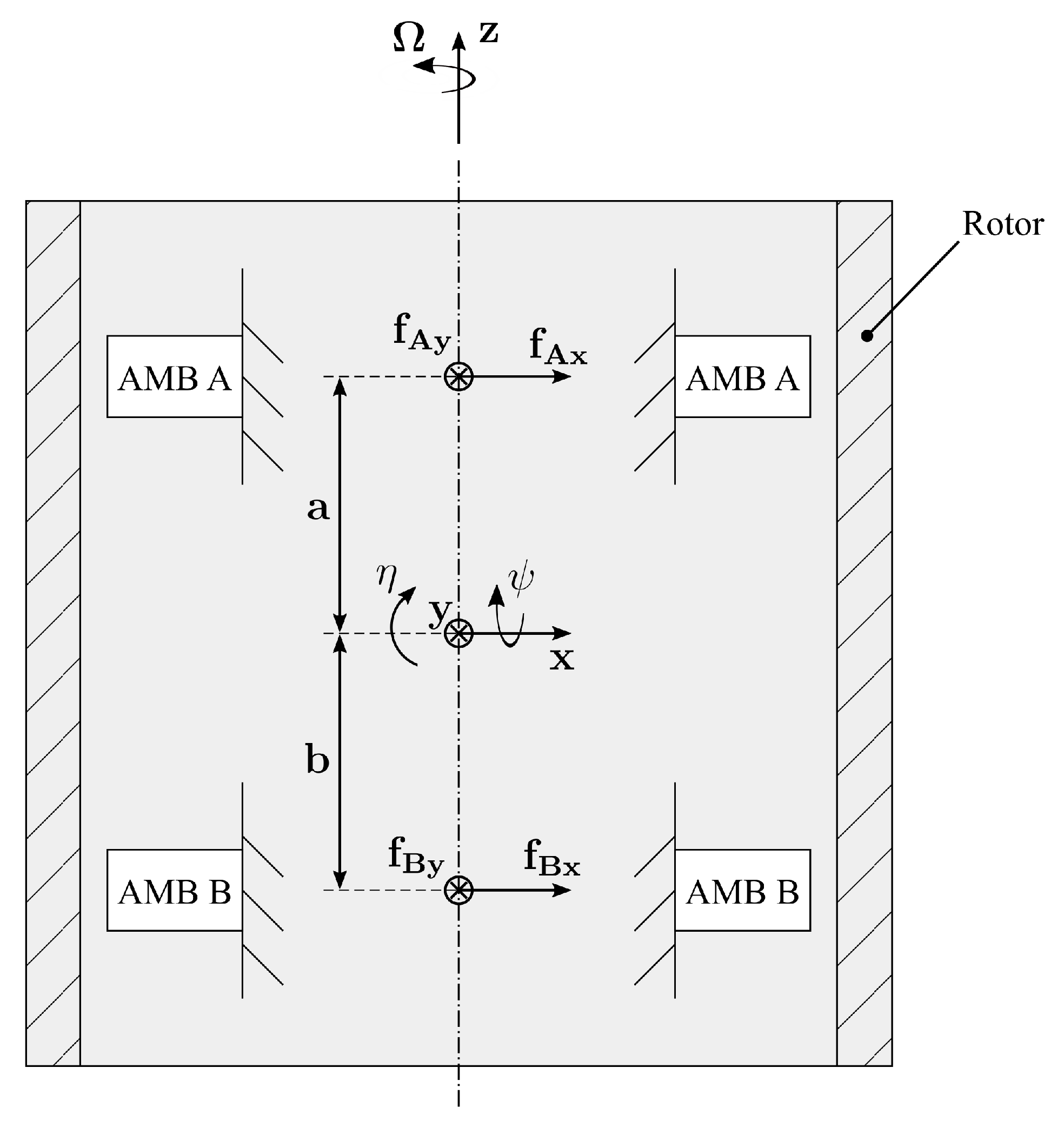
Figure 7 shows a schematic of the rigid rotor on AMBs.
The dynamics of the rigid rotor on AMBs at constant spin speed [3,34] is governed by
M q ¨ + Ω G q ˙ = f unb + f ext ,
where
M = d i a g I t m I t m , G = 0 0 I p 0 0 0 0 0 I p 0 0 0 0 0 0 0 , f unb = Ω 2 χ ( I p I t ) cos Ω t m ϵ cos Ω t χ ( I p I t ) sin Ω t m ϵ sin Ω t ,
m, I t and I p are the rotor mass, transversal moment of inertia and polar moment of inertia, respectively, and t is the simulation time. m ϵ and χ ( I p I t ) are the static and couple unbalance, which are computed in accordance with the standards reported in [34] (the quality grade suggested for flywheels is G 6.3). The values of these parameters are reported in Table 4.
The vector q = [ η x ψ y ] T contains the generalized coordinates of the rotordynamics (x and y are the translational degrees of freedom, η and ψ are the rotational ones, as illustrated in Figure 7), and f ext is the vector of the external forces acting on the rotor:
f ext = f dist + B T f AMB , B T = a b 0 0 1 1 0 0 0 0 a b 0 0 1 1 , f AMB = f A x f B x f A y f B y ,
where a = 220 mm and b = 220 mm are the coordinates of the radial AMBs with respect to the origin of the x y z -reference frame. f dist is the vector of the external disturbances acting on the flywheel. The vector f AMB contains the forces provided by the AMBs, where f i j is the force of the AMB i along the j-axis. Two counteracting electromagnets, driven in the differential driving mode [3], are employed along each axis of the AMB. By considering the j-axis of the AMB i, f e , i j + and f e , i j are defined as the forces provided by the electromagnets supplied with the currents i 0 + i c , i j and i 0 i c , i j , respectively, where i 0 is the bias current and i c , i j is the control current at the j-axis of the AMB i. The latter is determined by the PD controller, which receives as input the displacement of the flywheel at the AMB location [3]. The parameters of the PD controller are reported in Table 5.
The force f i j is computed as
f i j = f e , i j + f e , i j
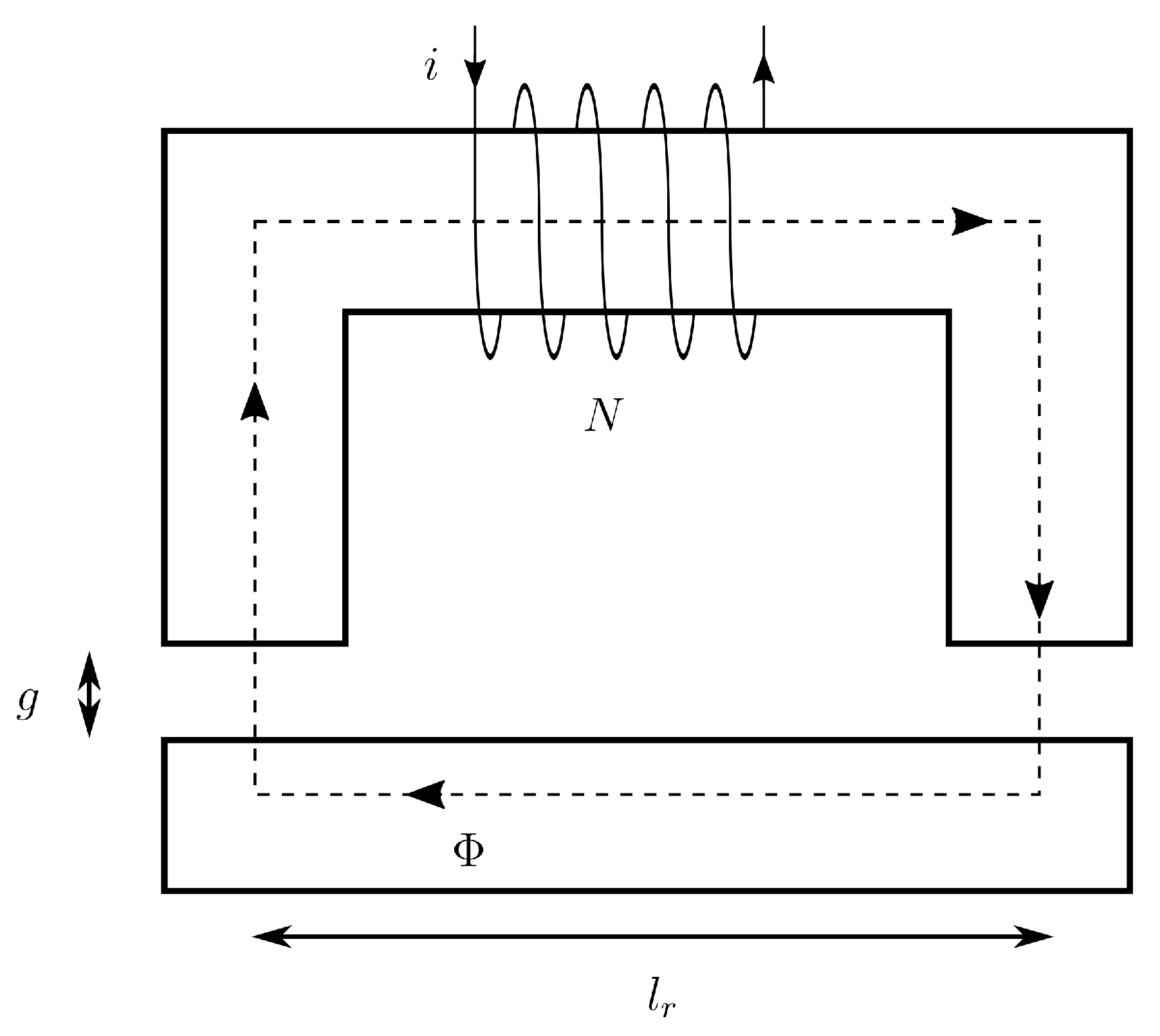
A one-dimensional approach is used to achieve the force f e produced by the electromagnet. The magnetic circuit of the electromagnet is sketched in Figure 8, where l r is the length of the magnetic flux path in the rotor and g is the magnetic gap. The current i flows into the coil and forces the magnetic flux Φ , which is constant if flux leakages are neglected, in the magnetic circuit.
Ampère’s law can be applied to the circuit:
H s l s + 2 H g g + H r l r = N i ,
where l s is the length of the flux path in the stator, N is the number of turns of the coil and H is the magnetic field strength (the subscript s refers to the stator, g to the magnetic gap, r to the rotor). The core of the electromagnet is made of laminated silicon steel, whose magnetic behavior can be approximated linearly. By introducing the linear magnetic characteristics of soft-iron and free-space, Equation (15) gives
Φ A s l s μ 0 μ s + 2 Φ A p g μ 0 + H r l r = N i ,
where A s and A p are the cross-sectional areas of stator and magnetic gap, respectively, μ 0 is the permeability of free-space and μ s is the relative permeability of silicon steel. The latter is significantly larger than the permeability of the free space, therefore the term referring to the stator can be neglected. If the cross-sectional areas along the flux path do not change, the magnetic flux density B is constant ( B s = B a = B r = B) and Equation (16) gives
B = μ 0 2 g N i μ 0 l r 2 g H r .
It is the load curve of the rotor material, which is a negative slope line in the B-H diagram whose distance from the origin mainly depends on the current supplied to the coil. The operating point of the rotor material yields from the intersection between the load curve and the magnetic characteristic of the rotor material. The procedure is similar to that adopted for the operating point of a permanent magnet [41]. In the present case, the demagnetization line of the permanent magnet is substituted by the magnetic characteristic of the rotor material. The latter exhibits a magnetic hysteretic behavior, which is represented through the Jiles–Atherton model [42,43]. The magnetic constitutive relation of the rotor material is
B = μ 0 ( H r + M r ) ,
where the magnetization M r is obtained from the first order differential equation of the Jiles–Atherton model
d M r d H r = c d M r , a n d H r , e f f + 1 c δ k δ M r , a n M r , i r r d H r , e f f d H r , δ = s g n ( d H r , e f f ) , δ = 1 i f M r , a n M r , i r r d H r , e f f > 0 0 otherwise .
The parameter c describes the magnetization reversibility and k is the pinning coefficient. M r , a n is the anhysteretic magnetization, and H r , e f f is the effective magnetic field
H r , e f f = H r + α M r ,
where α represents the interdomain coupling. The anhysteretic magnetization M r , a n is expressed through the Langevin function
M r , a n = M s coth H r , e f f a a H r , e f f .
The parameters needed to represent magnetic characteristic of the FeCrCo 48/5 (Table 6) have been identified by means of the least-squares optimization method proposed by Kis and Iványi [44]. The identification has been based on the material hysteresis loop measured on FeCrCo 48/5 SHMM samples by means of a vibrating-sample magnetometer (VSM). Figure 9 shows the comparison between the experimental and the numerical hysteresis loop. Equation (19) requires the initial condition of the magnetization M r , which is computed through the constitutive relation (Equation (18)) by providing the initial magnetic field H r , 0 and the initial magnetic field density B 0 . Therefore, the magnetic characteristic of the rotor material can be written as
B = B ( H r , H r , 0 , B 0 ) .
The intersection between Equations (17) and (22) is solved numerically at each step time of the simulation and gives the operating point of the rotor material ( H ¯ r , B ¯ ). Note that the numerical implementation of the model requires that the initial condition of Equation (22) at the step time n is the operating point of the rotor material at the preceding step time ( H ¯ r , n 1 , B ¯ n 1 ). The force that the electromagnet generates yields from the Maxwell stress tensor [41]. The one-dimensional approach considers a constant flux density across the magnetic gap, hence the Maxwell stress tensor gives
f e = A p μ 0 B ¯ 2 .
The force f e is computed for both the counteracting electromagnets and then it is introduced into Equation (14) to achieve the force that the AMB generates along the considered direction.
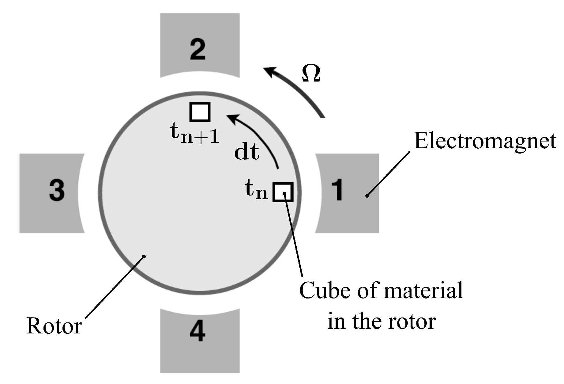
In the case of the spinning flywheel, the model needs to be modified to consider the residual magnetization effect of the hysteresis phenomenon. Figure 10 displays a sketch of a generic rotor with the four electromagnets of the AMB. A small cube of material is highlighted. At the time t n , it interacts with Electromagnet 1 and, consequently, the material operating point is ( H ¯ r , n , B ¯ n ) 1 . When the rotor rotates, the cube of material leaves the electromagnet 1 but keeps its magnetization. As soon as it approaches the region of Electromagnet 2, its operating point will depend on the operating point at the previous electromagnet. The modeling approach considers that the step time d t is one quarter of the rotational period. Therefore, it is the time that the cube of material needs to move from one electromagnet to the next. Furthermore, the operating point of the rotor material is assumed not to change in between the two electromagnets. This is implemented by providing the proper initial condition at Equation (22). By considering Electromagnet k at the time t n + 1 , the initial condition to be provided is the operating point ( H ¯ r , n , B ¯ n ) k 1 of the preceding Electromagnet k 1 at the previous step time t n .

5. Results

The model of the suspended flywheel is used to simulate the response to an external disturbance at Ω = 0 rpm and the response to the unbalance at the maximum speed Ω = 18,000 rpm. The former allows investigation of the magnetic hysteresis effect on the magnetic suspension. The latter is needed to assess the performance of the system at the maximum speed of the flywheel.

5.1. Response to the External Disturbance at Standstill

The system at standstill is disturbed by exerting a force step to the rotor center of mass. Therefore, the load is divided symmetrically on the two actuation stages. The response of only one AMB along the perturbed direction is reported since both the AMBs respond in the same way. The response of the system is compared with the response of a similar system, which approximates linearly the FeCrCo 48/5 magnetic behavior. For this purpose, the magnetic characteristic of the rotor material (Equation (22)) is substituted by a linear relationship B = μ 0 μ r H r , where μ r = 13 is yielded from the slope of the first magnetization curve of the FeCrCo 48/5.
Figure 11a,b show the resulting displacement of the rotor at the location of the radial AMBs for step amplitudes of 100 N and 300 N, respectively. One of the major effects of the hysteresis phenomenon is that the AMB is less responsive to a current change, which can be attributed to a lag between the input and the output of the AMB. This effect is evident from the response of the system; the force generated by the AMB (Figure 11c,d rises more slowly with respect to the system with linearized rotor material whereas the current change is quicker (Figure 12). The current in the case of the 300-N step amplitude saturates at 10 A. Another important effect of the hysteresis is the residual magnetization of the rotor material. This aspect is investigated at various step amplitudes by considering the steady-state response of the force provided by the most loaded electromagnet (Figure 13a). Such force, in the case of hysteretic rotor material, is composed of two contributions: the residual force (dash-dotted line), which is due to the residual magnetization of the rotor material, and the current-related force (dashed line), which is due to the supplied current. The residual magnetization contributes mainly to the total force (solid line). This force is higher than that required by the load (half of the load applied to the center of mass) because it includes the balancing of the counteracting electromagnet force due to the residual magnetization. On the other hand, in the linearized rotor material case (solid line with circles) this effect is not present and, consequently, the value of force is lower. The current requested by the electromagnet (Figure 13b) in the hysteretic rotor material case (solid line) is significantly lower than the current needed in the linear rotor material case (solid line with circles). The residual magnetization and hence the residual force increases with the amplitude of the transient current overshoot (dash-dotted line), whose value is reported in Figure 13b. When the step amplitude is lower than 150 N, the increase in the total force is compensated by the residual force. The resulting control current ( i c ) that has to be summed to the bias ( i 0 ) is then small. As the current overshoot starts saturating, the force requested to the current is higher. It is worth mentioning that, as stated in [45], the SHMM-based magnetic suspension features a reduced force capability when compared to common solutions with soft iron.

5.2. Response to the Unbalance at Maximum Speed

The response to the unbalance is evaluated at 18,000 rpm. The material of the rotor is considered magnetically virgin when the simulation starts, hence the homogeneous condition ( H 0 , B 0 ) = ( 0 , 0 ) is provided to each electromagnet. The initial conditions of the generalized coordinates of the lateral dynamics ( q ) are homogeneous. The unbalance force appears suddenly as soon as the simulation starts, hence the rotor is subject to a step force and a transient response is present. The force step at the starting time needs to be avoided in order to limit the transient time and achieve the steady state response in a shorter simulation time. For this purpose, the unbalance signal is multiplied by a gain which ramps linearly from 0 to 1 in 0.02 s.
Figure 14a,b show the maximum displacement of the rotor at the location of the radial AMBs. The maximum amplitude at steady state occurs at the AMB B. It is one order of magnitude lower than the nominal magnetic gap, hence the response is satisfactory. The forces provided by each AMB are reported in Figure 14c,d. Figure 14e,f show the currents required for the generation of such forces. Their values are smaller than the allowable continuous current that can be supplied to the electromagnets (Table 3).

6. Conclusions

This paper presented a novel FESS layout featuring a shaftless flywheel made of FeCrCo 48/5 SHMM on self-bearing hysteresis drives. The study of the stress due to the centrifugal effect led to the design as well as an assessment of the flywheel maximum speed and its energetic features. The rotordynamic analysis, performed by means of a three-dimensional FE approach, showed that the rotor deformation modes were well above the maximum speed of the flywheel, which was thus considered as a rigid body in the consecutive analyses. The performance of the radial SHMM-based magnetic suspension was investigated by considering two homopolar radial AMBs instead of the radial self-bearing drives. The modeling of the suspended flywheel was presented and the responses to both the external step force at standstill and to the unbalance at the maximum speed were achieved. These analyses allowed to highlight the main effects of the hysteresis of the rotor material on the magnetic suspension and to prove its satisfactory performance at the maximum speed of the flywheel.
The presented study led to the evaluation of the flywheel energetic features and the assessment of the radial magnetic suspension performance. Future work can include a detailed self-bearing drive study in order to consider both its bearing and electric machine operations.

Author Contributions

Conceptualization, S.C.; Investigation, S.C., A.B. and C.L.; Methodology, P.K., N.A. and A.T.; Supervision, P.K., N.A. and A.T.; Writing—original draft, S.C.; Writing—review & editing, A.B., C.L., P.K. and A.T.

Funding

This research received no external funding.

Conflicts of Interest

The authors declare no conflict of interest.

Nomenclature

SymbolDescriptionUnit
A p Pole aream2
A s Cross-sectional area of the statorm2
β Ratio between the inner and outer radius-
B T Transformation matrix for the AMBs forces-
BMagnetic flux densityT
χ ( I p I t ) Couple unbalancekgm2
E M a x Storage capabilityJ
f AMB Vector of the AMBs forces-
f ext Vector of the external forces-
f unb Vector of the unbalance force-
f e Electromagnetic forceN
f e , i j + Force provided by the electromagnet supplied with the current i 0 + i c , i j N
f e , i j Force provided by the electromagnet supplied with the current i 0 i c , i j N
f i j Force of the AMB i along the j-axisN
G Gyroscopic matrix-
gMagnetic gap lengthm
g 0 Nominal magnetic gapm
H ¯ r , B ¯ Magnetic operating point of the rotor materialA/m
hFlywheel heightm
H g Magnetic field strength in the magnetic gapA/m
H r Magnetic field strength in the rotorA/m
H s Magnetic field strength in the statorA/m
iCurrentA
i 0 Bias currentA
I p Polar moment of inertiakgm 2
I t Transversal moment of inertiakgm 2
i c , i j Control current at the j-axis of the AMB iA
i m a x Maximum continuous currentA
KFlywheel shape factor-
l r Length of the magnetic flux path in the rotorm
l s Length of the magnetic flux path in the statorm
μ 0 Magnetic permeability of the free-spaceH/m
μ r Magnetic permeability of the linearized rotor material-
μ s Magnetic permeability of the stator material-
M Mass matrix-
mϵStatic unbalancekgm
mMasskg
ν Poisson ratio-
NTurns per electromagnet-
Ω Spin speedrad/s
ω Natural frequencyrad/s
Ω B u r s t Burst spin speedrad/s
Ω M a x Maximum spin speedrad/s
Φ Magnetic fluxWb
q Vector of the generalized coordinates-
ρ Mass densitykg/m 3
r i Flywheel inner radiusm
r o Flywheel outer radiusm
rFlywheel radiusm
σ h Hoop stressPa
σ e q Von Mises equivalent stressPa
σ l i m Maximum equivalent stress in normal operationPa
S F Ω Safety factor on the spin speed-
σ r Radial stressPa
S U T Tensile strengthPa
tSimulation times

References

  1. Aneke, M.; Wang, M. Energy storage technologies and real life applications—A state of the art review. Appl. Energy 2016, 179, 350–377. [Google Scholar] [CrossRef]
  2. Amirante, R.; Cassone, E.; Distaso, E.; Tamburrano, P. Overview on recent developments in energy storage: Mechanical, electrochemical and hydrogen technologies. Energy Convers. Manag. 2017, 132, 372–387. [Google Scholar] [CrossRef]
  3. Bleuler, H.; Cole, M.; Keogh, P.; Larsonneur, R.; Maslen, E.; Okada, Y.; Schweitzer, G.; Traxler, A. Magnetic Bearings: Theory, Design, and Application to Rotating Machinery; Springer Science & Business Media: Berlin/Heidelberg, Germany, 2009. [Google Scholar]
  4. Baumgartner, T.; Burkart, R.M.; Kolar, J.W. Analysis and Design of a 300-W 500,000-r/min Slotless Self-Bearing Permanent-Magnet Motor. IEEE Trans. Ind. Electron. 2014, 61, 4326–4336. [Google Scholar] [CrossRef]
  5. Filatov, A.; Hawkins, L.; McMullen, P. Homopolar Permanent-Magnet-Biased Actuators and Their Application in Rotational Active Magnetic Bearing Systems. Actuators 2016, 5, 26. [Google Scholar] [CrossRef]
  6. Lusty, C.; Bailey, N.Y.; Keogh, P.S. Control of Flexible Rotor Vibration with Flexibly Mounted Active Magnetic Bearings. In Proceedings of the 10th International Conference on Rotor Dynamics—IFToMM; Cavalca, K.L., Weber, H.I., Eds.; Springer International Publishing: Cham, Switzerland, 2019; pp. 65–73. [Google Scholar]
  7. Bonfitto, A.; Botto, G.; Chiaberge, M.; Suarez Cabrera, L.; Tonoli, A. A multi-purpose control and power electronic architecture for active magnetic actuators. In Proceedings of the 2012 15th International Power Electronics and Motion Control Conference (EPE/PEMC); Novi Sad, Serbia, 4–6 September 2012.
  8. Ferreira, J.; Maslen, E.; Fittro, R. Transpermeance Amplifier Applied to Magnetic Bearings. Actuators 2017, 6, 9. [Google Scholar] [CrossRef]
  9. Bonfitto, A.; Castellanos Molina, L.M.; Tonoli, A.; Amati, N. Offset-Free Model Predictive Control for Active Magnetic Bearing Systems. Actuators 2018, 7, 46. [Google Scholar] [CrossRef]
  10. Bonfitto, A.; Tonoli, A.; Silvagni, M. Sensorless active magnetic dampers for the control of rotors. Mechatronics 2017, 47, 195–207. [Google Scholar] [CrossRef]
  11. Castellanos, L.M.; Bonfitto, A.; Tonoli, A.; Amati, N. Identification of Force-Displacement and Force-Current Factors in an Active Magnetic Bearing System. In Proceedings of the 18th Annual IEEE International Conference on Electro Information Technology, Rochester, MI, USA, 3–5 May 2018. [Google Scholar]
  12. Noshadi, A.; Shi, J.; Lee, W.S.; Shi, P.; Kalam, A. System Identification and Robust Control of Multi-Input Multi-Output Active Magnetic Bearing Systems. IEEE Trans. Control Syst. Technol. 2016, 24, 1227–1239. [Google Scholar] [CrossRef]
  13. Morais, T.; Der Hagopian, J.; Steffen, V., Jr; Mahfoud, J. Modeling and identification of electromagnetic actuator for the control of rotating machinery. Shock Vib. 2013, 20, 171–179. [Google Scholar] [CrossRef]
  14. Chiba, A.; Fukao, T.; Ichikawa, O.; Oshima, M.; Takemoto, M.; Dorrell, D.G. Magnetic Bearings and Bearingless Drives; Elsevier: Oxford, UK, 2005. [Google Scholar]
  15. Noh, M.; Gruber, W.; Trumper, D.L. Hysteresis Bearingless Slice Motors With Homopolar Flux-Biasing. IEEE/ASME Trans. Mech. 2017, 22, 2308–2318. [Google Scholar] [CrossRef] [Green Version]
  16. Gruber, W.; Rothbock, M.; Schob, R.T. Design of a Novel Homopolar Bearingless Slice Motor With Reluctance Rotor. IEEE Trans. Ind. Appl. 2015, 51, 1456–1464. [Google Scholar] [CrossRef]
  17. Mousavi, G.S.; Faraji, F.; Majazi, A.; Al-Haddad, K. A comprehensive review of Flywheel Energy Storage System technology. Renew. Sustain. Energy Rev. 2017, 67, 477–490. [Google Scholar] [CrossRef]
  18. Sun, Y.; Tang, J.; Shi, K. Design of a Bearingless Outer Rotor Induction Motor. Energies 2017, 10, 705. [Google Scholar]
  19. Severson, E.; Nilssen, R.; Undeland, T.; Mohan, N. Suspension force model for bearingless AC homopolar machines designed for flywheel energy storage. In Proceedings of the 2013 7th IEEE GCC Conference and Exhibition (GCC), Doha, Qatar, 17–20 November 2013; pp. 274–279. [Google Scholar]
  20. Ooshima, M.; Kobayashi, S.; Tanaka, H. Magnetic suspension performance of a bearingless motor/generator for flywheel energy storage systems. In Proceedings of the 2010 IEEE Power and Energy Society General Meeting, Providence, RI, USA, 25–29 July 2010; pp. 1–4. [Google Scholar]
  21. Asami, K.; Chiba, A.; Rahman, M.A.; Hoshino, T.; Nakajima, A. Stiffness analysis of a magnetically suspended bearingless motor with permanent magnet passive positioning. IEEE Trans. Magn. 2005, 41, 3820–3822. [Google Scholar] [CrossRef]
  22. Stevens, K.; Thornton, R.; Clark, T.; Beaman, B.G.; Dennehy, N.; Day, J.H. A Shaftless Magnetically Levitated Multifunctional Spacecraft Flywheel Storage System. In Proceedings of the 25th Annual AAS Guidance and Control Conference, Breckenridge, CO, USA, 6–10 February 2002. [Google Scholar]
  23. Schaede, H.; Schneider, M.; Vandermeer, J.; Mueller-Stoffels, M.; Rinderknecht, S. Development of kinetic energy storage systems for island grids. In Proceedings of the 2015 International Renewable Energy Symposium, Windhoek, Namibia, 29–30 October 2015. [Google Scholar]
  24. Kailasan, A.; Dimond, T.; Allaire, P.; Sheffler, D. Design and Analysis of a Unique Energy Storage Flywheel System—An Integrated Flywheel, Motor/Generator, and Magnetic Bearing Configuration. J. Eng. Gas Turb. Power 2015, 137, 042505. [Google Scholar] [CrossRef]
  25. Tsao, P.; Senesky, M.; Sanders, S. An integrated flywheel energy storage system with homopolar inductor motor/generator and high-frequency drive. IEEE Trans. Ind. Appl. 2003, 39, 1710–1725. [Google Scholar] [CrossRef] [Green Version]
  26. Li, X.; Anvari, B.; Palazzolo, A.; Wang, Z.; Toliyat, H. A Utility-Scale Flywheel Energy Storage System with a Shaftless, Hubless, High-Strength Steel Rotor. IEEE Trans. Ind. Electron. 2018, 65, 6667–6675. [Google Scholar] [CrossRef]
  27. Amiryar, M.E.; Pullen, K.R. A Review of Flywheel Energy Storage System Technologies and Their Applications. Appl. Sci. 2017, 7, 286. [Google Scholar] [CrossRef]
  28. Sanders, S.; Senesky, M.; He, M.; Chiao, E. Low-Cost Flywheel Energy Storage Demonstration. In Energy Research and Development Division Final Project Report; Amber Kinetics, Inc.: Union City, CA, USA, 2015. [Google Scholar]
  29. Galluzzi, R.; Tonoli, A.; Amati, N. Magnetic hysteresis machines for next-generation electric turbochargers. In Proceedings of the 2017 International Conference of Electrical and Electronic Technologies for Automotive, Torino, Italy, 15–16 June 2017; pp. 1–5. [Google Scholar]
  30. Nasiri-Zarandi, R.; Mirsalim, M.; Tenconi, A. A Novel Hybrid Hysteresis Motor With Combined Radial and Axial Flux Rotors. IEEE Trans. Ind. Electron. 2016, 63, 1684–1693. [Google Scholar] [CrossRef]
  31. Kandil, M.S.; Dubois, M.R.; Bakay, L.S.; Trovao, J.P.F. Application of Second-Order Sliding-Mode Concepts to Active Magnetic Bearings. IEEE Trans. Ind. Electron. 2018, 65, 855–864. [Google Scholar] [CrossRef]
  32. Genta, G. Kinetic Energy Storage: Theory and Practice of Advanced Flywheel Systems; Butterworth-Heinemann: Oxford, UK, 2014. [Google Scholar]
  33. Kubota, T.; Wakui, G.; Itagaki, M. Hysteresis motor using magnetically anisotropic Fe-Cr-Co magnet. IEEE Trans. Magn. 1998, 34, 3888–3896. [Google Scholar] [CrossRef]
  34. Genta, G. Vibration Dynamics and Control; Springer: New York, NY, USA, 2009. [Google Scholar]
  35. Park, C.H.; Choi, S.K.; Son, Y.S.; Han, Y.H. Development of 5kWh Flywheel Energy Storage System Using MATLAB/xPC Target. In Proceedings of the 2009 WRI World Congress on Computer Science and Information Engineering, Los Angeles, CA, USA, 31 March–2 April 2009; pp. 701–705. [Google Scholar]
  36. Darrelmann, H. Comparison of high power short time flywheel storage systems. In Proceedings of the 1999 21st International Telecommunication Energy Conference (INTELEC’99), Copenhagen, Denmark, 9 June 1999; p. 589. [Google Scholar]
  37. Gruber, W.; Hinterdorfer, T.; Sima, H.; Schulz, A.; Wassermann, J. Comparison of different motor-generator sets for long term storage flywheels. In Proceedings of the 2014 International Symposium on Power Electronics, Electrical Drives, Automation and Motion (SPEEDAM), Ischia, Italy, 18–20 June 2014; pp. 161–166. [Google Scholar]
  38. Li, H.; Lam, K.Y.; Ng, T.Y. Rotating Shell Dynamics; Elsevier: Oxford, UK, 2005; Volume 50. [Google Scholar]
  39. Daneshjou, K.; Talebi, T.M.; Talebi, T.R. Vibration and Critical Speed of Axially loaded Rotating Orthotropic Cylindrical Shells. JAST 2007, 4, 1–7. [Google Scholar]
  40. Huang, S.; Hsu, B. Resonant phenomena of a rotating cylindrical shell subjected to a harmonic moving load. J. Sound Vib. 1990, 136, 215–228. [Google Scholar] [CrossRef]
  41. Furlani, E.P. Permanent Magnet and Electromechanical Devices: Materials, Analysis, and Applications; Academic Press: Cambridge, MA, USA, 2001. [Google Scholar]
  42. Szewczyk, R.; Zieliński, C.; Kaliczyńska, M. Recent Advances in Automation, Robotics and Measuring Techniques; Springer: New York, NY, USA, 2014; Volume 267. [Google Scholar]
  43. Bergqvist, A. A simple vector generalization of the Jiles–Atherton model of hysteresis. IEEE Trans. Magn. 1996, 32, 4213–4215. [Google Scholar] [CrossRef]
  44. Kis, P.; Iványi, A. Parameter identification of Jiles-Atherton model with nonlinear least-square method. Phys. B Condens. Matter 2004, 343, 59–64. [Google Scholar] [CrossRef]
  45. Circosta, S.; Galluzzi, R.; Bonfitto, A.; Castellanos, L.M.; Amati, N.; Tonoli, A. Modeling and Validation of the Radial Force Capability of Bearingless Hysteresis Drives. Actuators 2018, 7, 69. [Google Scholar] [CrossRef]
Figure 1. 3D cross-section view of the proposed FESS layout: ① Rotor; ② Hysteresis self-bearing drive; ③ Thrust AMB; ④ Flange; ⑤ Backup bearing; ⑥ Inner stator.
Actuators 07 00087 g001
Figure 2. Schematic of the self-bearing hysteresis drive. (a) View in the x y -plane (the transversal plane of the flywheel) with the three-phase (A, B, C) winding scheme of the motor-generator function. (b) Partial cross-section in the x z -plane (the longitudinal plane of the flywheel) with the winding scheme responsible for the suspension flux generation only. (c) Isometric view.
Actuators 07 00087 g002
Figure 3. Polar and transversal moment of inertia ratio of the flywheel versus inner and outer radius ratio (a). Flywheel height versus inner and outer radius ratio (b).
Actuators 07 00087 g003
Figure 4. Von Mises equivalent stress vs radius of the flywheel: analytical plane stress (solid); numerical finite-element (dash-dotted).
Actuators 07 00087 g004
Figure 5. Campbell diagram of the flywheel: conical rigid body mode (solid); forward (dashed with squares) and backward (dashed) pure radial modes; forward (dash-dotted with circles) and backward (dash-dotted) radial shearing modes; synchronous whirling (dotted). The forward and backward pure radial modes (dashed with squares and dashed, respectively) are superimposed.
Actuators 07 00087 g005
Figure 6. Pure radial (a) and radial shearing (b) mode shapes in the top, lateral and isometric view.
Actuators 07 00087 g006
Figure 7. Schematic of the rigid rotor on AMBs.
Actuators 07 00087 g007
Figure 8. Magnetic circuit of the electromagnet.
Actuators 07 00087 g008
Figure 9. Magnetic characteristic of the FeCrCo 48/5 alloy: experimental (solid) and numerical (dash-dotted) loop.
Actuators 07 00087 g009
Figure 10. Schematic of the spinning rotor.
Actuators 07 00087 g010
Figure 11. Response of the system with hysteretic (solid) and linearized (dash-dotted) rotor material to external force steps: displacement of the flywheel at the location of the radial AMBs for the 100-N (a) and the 300-N (b) step amplitude; force provided by each AMB for the 100-N (c) and the 300-N (d) step amplitude.
Actuators 07 00087 g011
Figure 12. Response of the system with hysteretic (solid) and linearized (dash-dotted) rotor material to external force steps: currents i 0 + i c (a) and i 0 i c (c) for the 100-N step amplitude; currents i 0 + i c (b) and i 0 i c (d) for the 300-N step amplitude.
Actuators 07 00087 g012
Figure 13. (a) Force provided by the most loaded electromagnet at steady state vs external force step applied to the rotor center of mass. Solid: total force (hysteretic rotor material case). Dash-dotted: residual force (hysteretic). Dashed: current-related force (hysteretic). Solid with circles: total force (linearized rotor material case). (b) Current supplied to the most loaded electromagnet at steady state vs external force step applied to the rotor center of mass. Solid: current (hysteretic rotor material case). Dash-dotted: maximum current overshoot (hysteretic). Solid with circles: current (linearized rotor material case).
Actuators 07 00087 g013
Figure 14. Responses to the unbalance: maximum displacement at the location of the AMB A (a) and the AMB B (b); force provided by the AMB A (c) and the AMB B (d); current supplied to the electromagnets of the AMB A (e) and the AMB B (f).
Actuators 07 00087 g014
Table 1. Properties of the FeCrCo 48/5 SHMM.
SymbolQuantityValue
ν Poisson ratio0.3
S U T Tensile strength1150 MPa
ρ Mass density7600 kg/m 3
Table 2. Dimensions of the flywheel.
SymbolQuantityValue
r i Inner radius135 mm
r o Outer radius150 mm
hHeight600 mm
Table 3. Main parameters of the radial AMB.
SymbolQuantityValue
A p Pole area2010 mm 2
g 0 Nominal magnetic gap0.8 mm
l r Length of the magnetic flux path in the rotor36 mm
NTurns per electromagnet174
i 0 Bias current2.5 A
i m a x Maximum continuous current5 A
Table 4. Mechanical parameters of the rotor.
SymbolQuantityValue
mMass61.2 kg
I t Transversal moment of inertia2.46 kgm 2
I p Polar moment of inertia1.25 kgm 2
χ ( I p I t ) Couple unbalance4.50 × 10−5 kgm2
mϵStatic unbalance2.05 × 10−4 kgm
Table 5. Parameters of the PD controller in the form of C ( s ) = P + D 1 + τ d s .
SymbolQuantityValue
PProportional gain12,039  A / m
DDerivative gain 111 A s / m
τ d Time constant 3.3 m s
Table 6. Parameters of the Jiles–Atherton model for the FeCrCo 48/5 SHMM.
SymbolQuantityValue
α Local field factor 0.15
cDomain rotation loss 0.20
aLangevin parameter 9.94 × 10 4 A / m
kPinning 5.16 × 10 4 A / m
M S Saturation magnetization 2.02 × 10 6 A / m

