1. Introduction
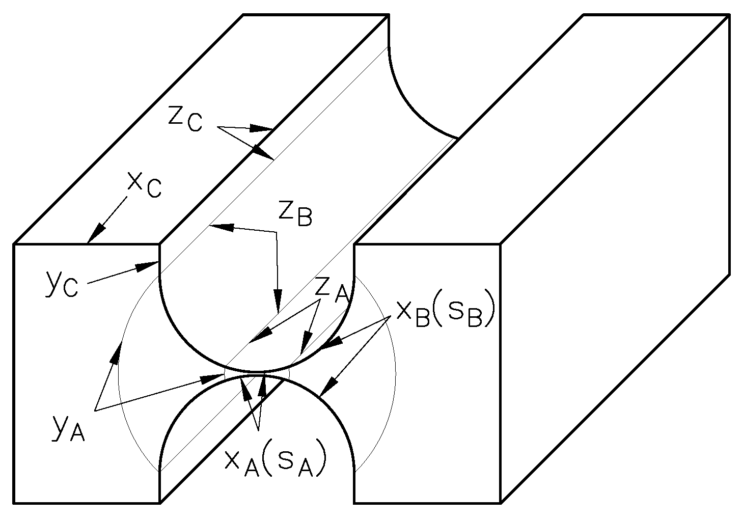
Due to their monolithic design, compliant mechanisms have significant advantages over rigid-body mechanisms for precision engineering applications and metrology [
1,
2,
3,
4] (e.g.,
Figure 1). Negligible friction, no stick-slip behavior, lack of clearance and backlash as well as smooth and highly repeatable motion are to be mentioned here. Their advantages further include compactness and lack of wear and maintenance. Since lubrication is not required, they are well suited for clean room and vacuum applications. Disadvantages of these mechanisms comprise limited motion, due to the tolerable stress (or strain), as well as inherent non-pure rotation of the flexure hinges.
Flexure hinges are materially coherent connections between two bodies or body segments with at least one relative motion due to mostly elastic deformation [
5]. Typical notch flexure hinges, as in
Figure 2, allow a relative rotation through bending of its neck-like region with concentrated compliance. The performance of compliant mechanisms in force measurement applications depends largely on the compliance or low stiffness of their joints. In those instruments, the rotation of the flexure hinges is limited by mechanical stops and a position control during operation, resulting in deflection ranges
. The bending stiffness defines the sensitivity of the force measurement. To enhance the sensitivity, the minimum notch height
h of the flexure hinges is reduced to a few hundredths of a millimeter [
6,
7] (see
Figure 1). This leads to difficulties in the accurate determination of the bending stiffness of very thin flexure hinges, since the assumptions of commonly used analytical modeling approaches no longer apply. With small notch heights, the mechanical properties become more sensitive to small imperfections, e.g., manufacturing and material related. To avoid parasitic motions, the lateral stiffnesses are usually increased by setting the width
b very large in comparison to the minimum notch height
h.
The article highlights the existing deviation of the bending stiffness calculated by known analytical equations and finite element models in comparison. The remaining sections are structured as follows.
Section 2 discusses the approaches for the modeling of flexure hinges.
Section 3 deals with the finite element (FE) modeling of thin flexure hinges. The deviation between results of analytical and FE models is explained in
Section 4. An approach for an accurate determination of the bending stiffness based on correction factors and its use in application examples are presented in
Section 5 and
Section 6, respectively. Finally, conclusions are drawn in
Section 7.
2. Approaches for Modeling the Bending Stiffness of Flexure Hinges
The literature provides numerous geometries for flexure hinges [
8,
9] with the semi-circular notch contour being the most prevailed (see
Figure 2). Most applications are based on single-axis notch flexure hinges to realize planar or spatial motions. Common approaches for the quasi-static modeling of these flexure hinges consider the notch contour as a beam with variable rectangular cross-section, i.e., variable height
, with one end fixed and the load applied on the opposing end. Due to the resulting deformation, the cross-section at the loaded end is displaced and rotated. The relative motion between both ends (points O and P in
Figure 2) can be formulated as:
Here
denotes the load vector,
the displacement vector and
the stiffness matrix. In general terms,
is a
matrix whose components describe the relationship between the components of the load and displacement vectors. To simplify the synthesis of compliant mechanisms, a flexure hinge is often modeled as a revolute joint with a torsional spring. The position of the substitute joint and the stiffness of the spring depend on the geometry and loading conditions of the flexure hinge [
10]. For hinges with concentrated compliance, common in high-precision systems [
1,
2,
4], this location can be assumed at their geometrical center (point C in
Figure 2) [
11]. This way, the stiffness of the equivalent spring no longer depends on the type of load [
10]. In analogy to the rotational stiffness of the spring, the bending stiffness
of these hinges can be approximated by
where
M is the applied bending moment and
the resulting rotation angle, both about the
z-axis. Based on this characterization, many authors have derived analytical and approximate equations for calculating the bending stiffness using different theories. A survey of existing modeling approaches and common model assumptions [
8,
10] in the literature is presented in
Table 1.
The assumptions in
Table 1 serve as the basis for deriving the well-known Euler-Bernoulli’s bending differential equation. In fact, the analytical equations by Paros and Weisbord [
12], Lobontiu [
9] and Li et al. [
13] are exact solutions of the differential equation for various notch contours using different methods. Zhu et al. [
14] proposes a numerical approach to determine the overall compliance by summating the compliances of a finite number of short Euler-Bernoulli beams. Other approaches have been used to obtain more accurate and tractable equations, especially the FE method [
2,
19,
20]. Dirksen and Lammering [
15] take the often-neglected shear deformation into account to derivate equations for rectangular flexure hinges. The equations by Tseytlin [
16] are approximations for different geometry ranges from the plane equations of continuum mechanics. In contrast to the previous approaches, the nonlinear theory in [
10] considers large deformations of rod-like structures and can be only solved numerically, as implemented in the design tool by Henning et al. [
18]. The contour-dependent design equations by Linß et al. [
17] are approximated from the results obtained using the model equations in [
10]. These simplifications produce important deviations in the determination of the bending stiffness of flexure hinges with general dimensions [
21,
22].
Other effects, often neglected in analytical approaches, are to be expected in flexure hinges. Among them are stress concentration [
15] and anticlastic bending [
23]. On the one hand, a changing cross-section generates peaks of the bending stress in the thinnest region. On the other hand, the anticlastic shape due to the Poisson’s effect in plates under bending is restrained producing a local state of plane strain at the center region. It is important to remark the effects unrelated to modeling that can alter the bending stiffness, e.g., axial loads [
24] or manufacturing imperfections [
25]. Modeling deviations are accepted by some authors since they lie near those caused by manufacturing errors [
15]. However, this cannot be consistently assumed due to the vast number of parameters involved. A more extensive study on this matter is yet to be done, especially for very thin flexure hinges, which are typical in high-precision measurement instruments.
Most of the assumptions in
Table 1 lead to small errors in precision engineering applications. However, the assumption of a plane stress state is problematic due to the large aspect ratios of thin flexure hinges. The validity of this assumption needs to be verified with the help of FE models. The FE model itself must be carefully prepared to reduce the influence of other effects and to achieve a meaningful interpretation of later results.
3. Finite Element Modeling of Thin Flexure Hinges
The investigation on the deviation between different models requires the selection of a suitable notch contour based on its significance in the field of application. Semi-circular contours are widely used in precision engineering, especially in weighing technology, due to their manufacturability with conventional processes and a high degree of motion accuracy for thin geometries [
3,
8]. Its widespread use has led to the development of numerous modeling equations [
2,
9,
12,
16,
17,
20]. The present investigation focusses on semi-circular flexure hinges which can be considered thin, as the one shown in
Figure 2.
There is no consistent definition of “thin” flexure hinges in the literature. In [
16], thin flexure hinges are defined as those whose deformation occurs mostly within the boundaries of the notch contour, which is a very general statement. Semi-circular contours are further classified in [
16] according to the ratio of minimum notch height
h to radius
R as: thin (
), intermediate (
) and thick (
). Thus, thin flexure hinges are mainly those with very small notch heights
h. The current limit in terms of manufacturing technology lies around 50
m [
7]. For the thinnest hinges, the typical ratio of width
b to minimum notch height
h is about 200 [
26], with ratios up to 375 still being achievable [
6]. The geometrical dimensions of the FE model of the flexure hinge were chosen according to typical values in precision measurement applications (see
Table 2). The material for this investigation is a high-strength aluminum alloy with an assumed linear elastic behavior [
27].
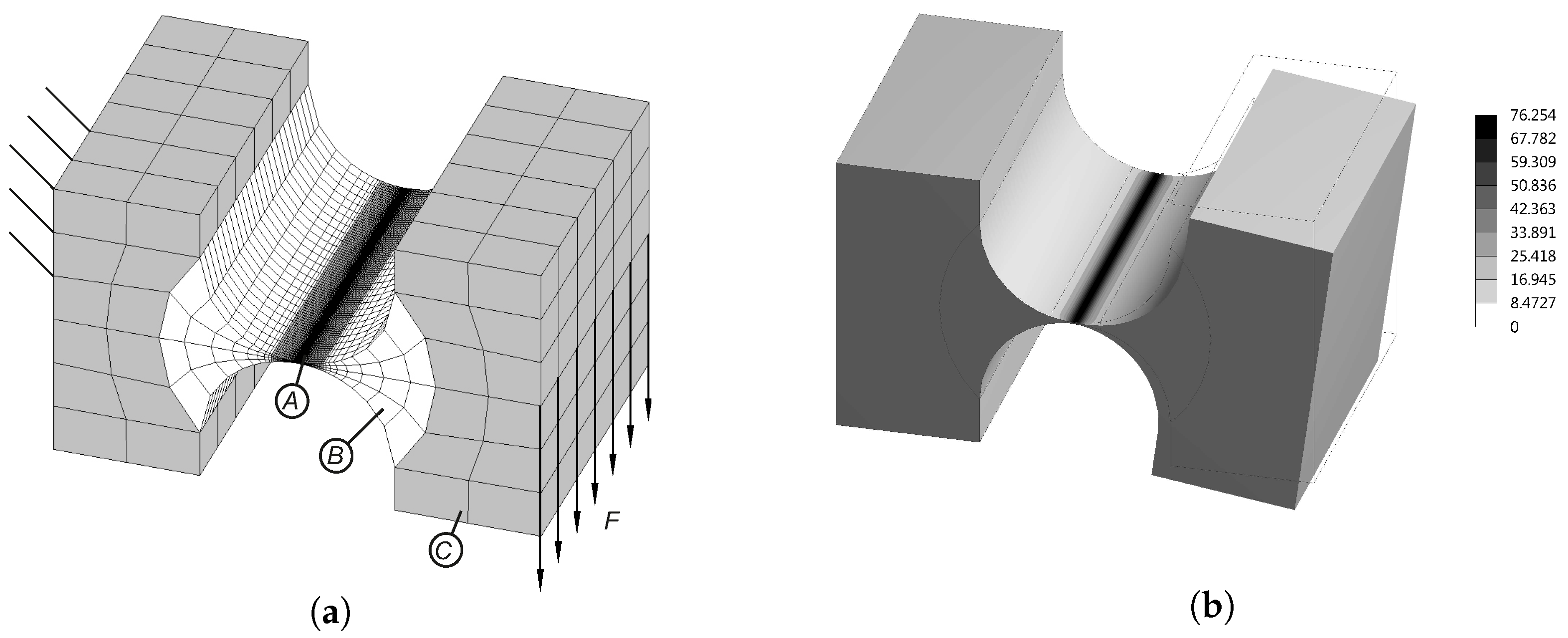
The simple geometry of a notch flexure hinge allows the use of a mapped mesh with hexahedral elements. However, the large aspect ratios of very thin hinges require special consideration. Here, an optimum between element quality and number of elements must be found. This can be achieved by using an appropriate meshing strategy. The proposed strategy shown in
Figure 3a and considers the following settings:
The domain is divided into three parts: a highly refined central zone (A), a transition zone (B) and a roughly meshed outer zone (C).
The boundary between the central zone (A) and the transition zone (B) is controlled so that the local normal stress in the x-direction is 10% of its maximum value.
The transition zone (B) is limited by the transition of the notch contour to the adjacent links.
In the central zone (A), the element size in the z-direction depends on the minimum element size in the x-y plane and a maximum aspect ratio of the hexahedral elements.
To reduce the distortion of the elements when adapting to the semi-circular contour, the zones are delimited by cylindrical surfaces.
The non-matching meshes are connected at their interface by suitable contact elements.
Elements with quadratic approximation functions are used to avoid shear locking.
Using this meshing strategy and the parameters in
Table 2, a sensitivity analysis is conducted with the parameters of the mesh in
Appendix A. Results show that the number and transition of elements in the
x-direction of zone (A) have significant influence on the convergence of the numerical solution of the maximum bending stress
. Other parameters have neglectible influence. Mesh parameter values are then selected, and convergence is studied. The total number of elements amounts to 18,912 to achieve convergence of the numerical solution of the bending stress
(see
Figure 3b).
The bending stiffness of the hinge is determined using Equation (2). The bending moment
M in the model is generated by a shear force
F parallel to the
z-axis applied to the edge of the free end with a lever arm of
to the assumed rotational center. The rotation angle
is calculated from the resulting displacements of two points of the free end (see
Figure 2). Using the parameter values in
Table 2, the bending stiffness of the semi-circular flexure hinge is calculated according to various models (for the corresponding assumptions refer to
Table 1). The results are shown in
Table 3. Not every model allows the calculation of large deformations, which requires a nonlinear consideration. In order to achieve a comparability of the results, the rotation angle of nonlinear models is limited to one degree (
). In this deflection range the validity of the linear beam theory can be assumed with sufficient accuracy. Applications which demand the highest precision often operate at small deflections to ensure linear material behavior [
28] and to avoid stiffening effects, e.g., anticlastic bending [
23].
There are significant differences between the results of analytical equations and the 3D-FE model. The result of 3D-FE model is about 10–12% stiffer than the analytical results, except for the equation according to Tseytlin [
16]. A modified elastic modulus
, which applies for plates and thin films, is considered in this equation [
29]. The factor
relates the flexural rigidity of a beam assuming a plane strain state and that of a beam assuming a plane stress state. The consideration of this factor corresponds to the model assumption of the plane strain state, which results in a better agreement with the results of the 3D-FE model with the parameters in
Table 2. However, the results of the equation by Tseytlin [
16] still show deviations not suitable for many other demanding precision applications with different typical geometric ratios. Thus, the development of more accurate equations based on a thorough understanding of the deviation causes becomes necessary.
4. Comparison between Analytical and Finite Element Models
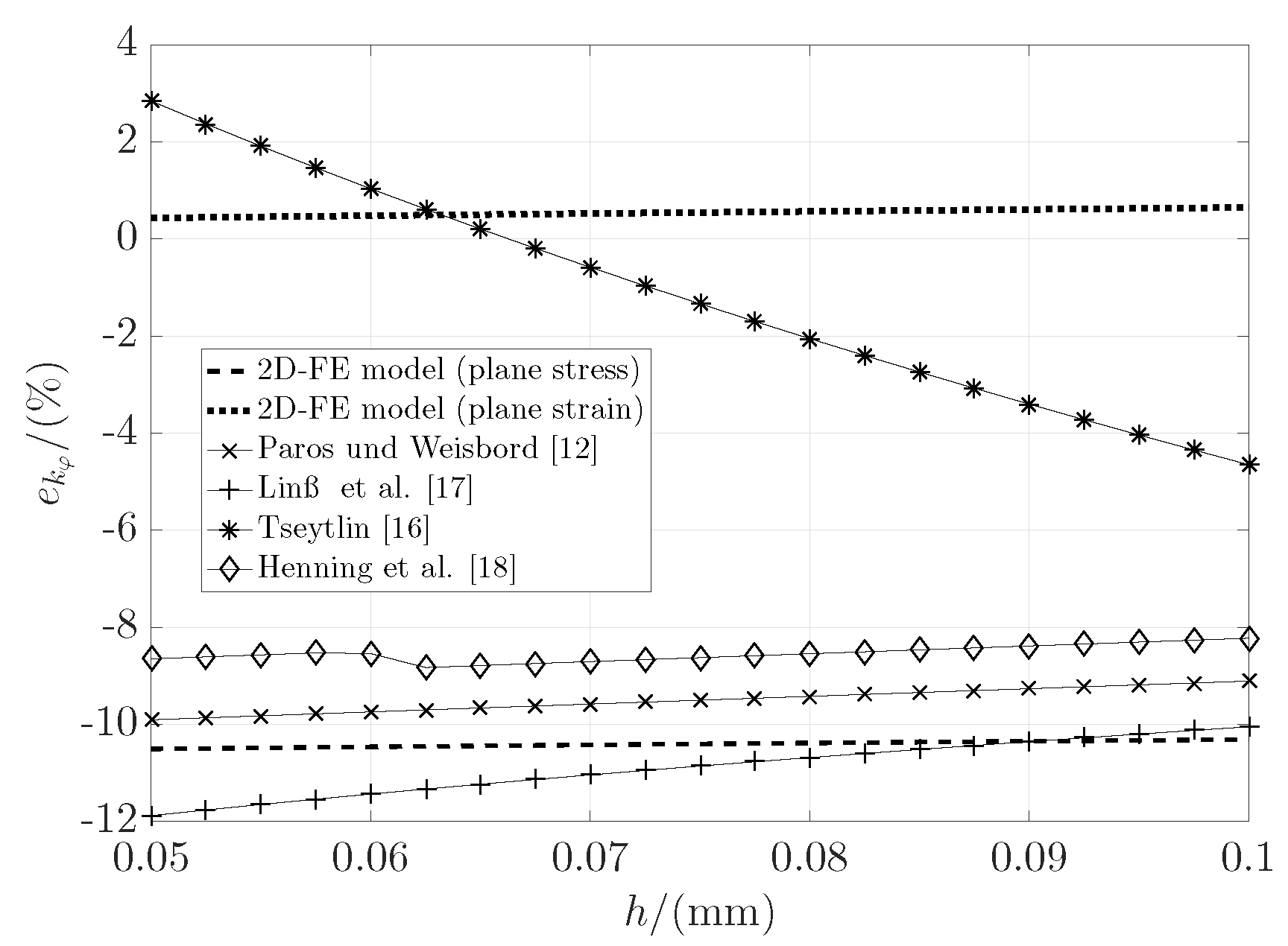
To better understand the observed behavior, the relative stiffness deviation of the analytical results compared to the results of the 3D-FE model is shown in
Figure 4 for minimum notch heights of 0.05 to 0.1 mm. Other parameter values and the number of elements remain constant. The analytical equation by Lobontiu [
9] is no longer considered, since the results are always identical to those by Paros and Weisbord [
12]. In addition, two nonlinear 2D-FE models, one assuming a plane stress state and one a plane strain state, are used for comparison. The mesh with 2D-elements is equal to the side face of the 3D-mesh.
The state of stress of a prismatic body, in which loading is uniformly distributed over its width, generally lies between two limiting cases: the plane stress state (for
b→ 0) and the plane strain state (for
b→∞) [
30]. In the plane stress state, the normal stress in the out-of-plane direction is assumed to be zero. In contrast, in a plane strain state, this stress is not zero, but is constantly distributed across the width and its value depends on the normal stresses in the
x-y plane. As a result, the bending strain is reduced according to Hooke’s law, increasing the bending stiffness by a factor of approximately
.
An out-of-plane normal stress is always present in the flexure hinge, which is not constantly distributed across the width and becomes zero at the boundary faces, i.e., anticlastic bending [
23]. In
Figure 5, the distribution of this stress is represented by means of a dimensionless out-of-plane normal stress
over the dimensionless
z-coordinate
in the outer transverse fiber at the thinnest region of the hinge (
mm). The dimensionless stress
is formulated as the quotient of the normal stress in one point and the maximum value across the width:
The distribution of the out-of-plane normal stress according to
Figure 5 shows that the state of stress of the 3D-FE model changes from plane stress to the plane strain with increasing width. As the width gets larger, the distribution of the out-of-plane normal stress becomes more uniform. Above a certain value of
b, the behavior converges near to plane strain and the stiffness becomes almost linearly proportional to the width. According to the analytical equations and 2D-FE models, the bending stiffness is always linearly proportional to the width
b (see
Appendix B). However, the behavior of
demonstrates a nonlinear relationship, meaning that the deviation depends on the width
b.
In [
21], it was demonstrated that the deviation between analytical equations and 2D-FE models in semi-circular flexure hinges depends only on the
ratio. This is related to the stress concentration occurring on the notch contour, which increases the bending strain in 2D-FE models, reducing the stiffness. Then, the deviation between the 3D-FE model and analytical equations must depend on
h,
R and
b, and possibly on other parameters such as
H and
L. Due to its importance and widespread use, the equation based on Euler-Bernoulli’s beam theory by Paros and Weisbord [
12] is used for comparison. The equations by Linß et al. [
17] and Tseytlin [
16] do not apply for the geometries considered here, since they exceed the theoretical limits in
Figure 4. This is due to their approximation nature. The equation by Tseytlin [
16] delivers results closer to the 3D-FE model using the parameters in
Table 2 but can be highly inaccurate for other geometries [
21].
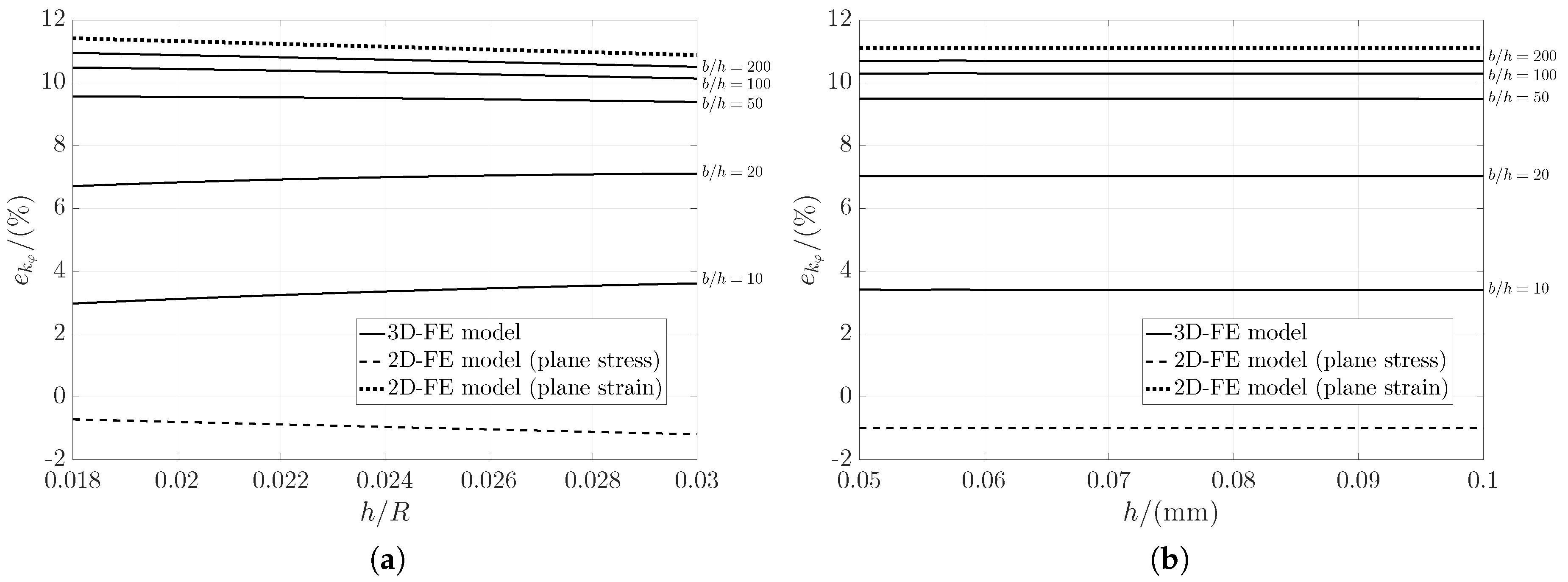
The relative deviation of FE models to the equation by Paros and Weisbord [
12] is calculated for the geometric ratios
and
and is presented in
Figure 6a. Results show the expected multi-criteria effect in the deviation of the 3D-FE model but is also present between 3D- and 2D-FE models, especially for low
values. Nevertheless, when fixing
to a certain value (
) the deviations becomes constant for discrete
ratios (see
Figure 6b). From this, it can be concluded that the deviation of the results of analytical models to the 3D-FE model depends only on the ratios
and
rather than on absolute values of the geometrical parameters. This is promising for the development of accurate design equations for the calculation of the bending stiffness of flexure hinges with circular contours. It should be noted, however, that the total height
H may have a relevant effect for thicker hinges or incomplete circular contours (
) [
17]. The study of a complete semi-circular contour is very convenient because it can be described by only two parameters,
h and
R. Other contours are described by three or more parameters, e.g., elliptical contour, which increases the complexity of the deviation.
In [
22], a modified elastic modulus, which depends only on
, was presented as a correction factor to reduce the deviation when using a 2D-FE model assuming plane stress. However, this factor does not take into account the relationship between
and
and was derived using a discrete
ratio of 0.8. This causes large deviations for small
values (see
Figure 7). A more precise equation for calculating the bending stiffness based on FEM-based correction factors is derived in the following section.
5. Correction Factors for the Accurate Determination of the Bending Stiffness
The described deviation between model results serves as the basis for the development of a correction factor for the results of analytical equations based on the assumptions of the Euler-Bernoulli beam theory (BT) (see
Table 1). The factor equation is approximated by analyzing the different effects separately and is formulated as follows:
In this case,
is a correction factor for the deviation between the 2D-FE plane stress model and the beam-theory equation by Paros and Weisbord [
12], which is a result of an inaccurate consideration of the stress distribution in the contour. The factor
corrects the deviation between the 2D-FE plane stress model and the 3D-FE model due to neglecting of the out-of-plane normal stress. Thus, the total correction factor
, which takes into account the effects of both contour and width, can be calculated.
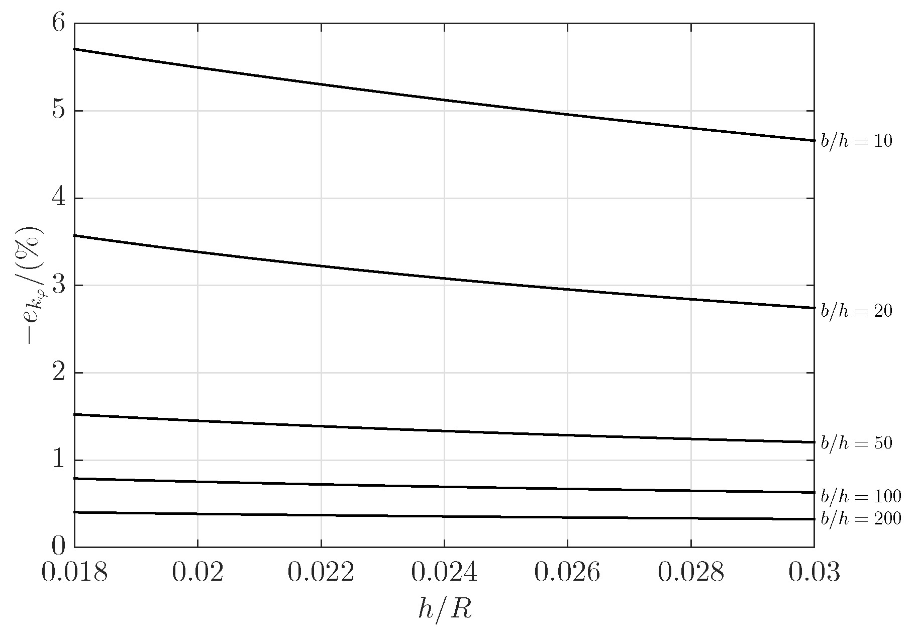
The correction factors
and
can be calculated from the respective relative stiffness deviations
and
:
The stiffness deviations
and
are approximated as functions of the corresponding parameters
and
using calculated support points. The results in
Figure 6b show that the uniform scaling of the hinge does not affect the deviation. Thus, the calculation of the support points can be conducted for a fixed parameter, e.g., the radius
R, and the resulting function would still apply to any parameter values under the same geometric ratios. The results of the support points are calculated for
from 0.015 to 0.15 and
from 10 to 100, with more calculation points by
between 10 and 60 due to the strong nonlinearity in this region, and a fixed radius
R of 3 mm.
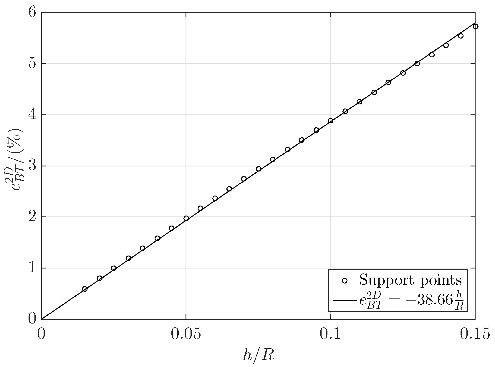
Since the relative deviation
depends linearly on the
ratio, it can be approximated with a polynomial of first order (see
Figure 8). This results in the correction factor for the deviation of the analytically determined bending stiffness to the plane stress state (2D-FE model) to:
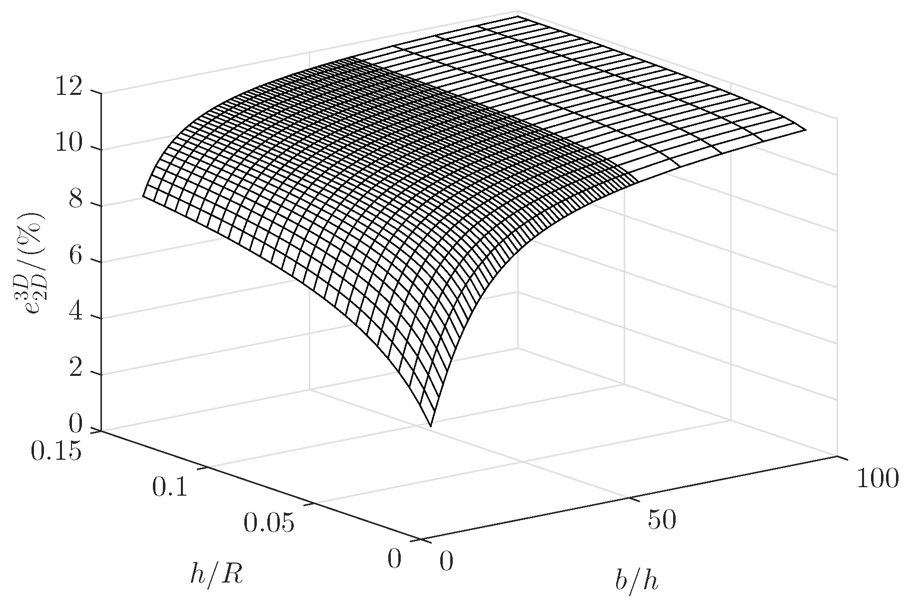
The deviation
is influenced by various parameters, which makes the search for a suitable function more complicated. An approximation of
as a function of
and
would apply only to the material used. The effect of the transverse contraction is still to be considered. Conveniently,
should always converge to
(see
Figure 9). It is assumed that a normalized deviation
depends only on
and
. In essence,
serves as a factor for the transition from the plane stress state (
) to the plane strain state (
). Based on the similarity of the behavior of the deviation for each discrete
value shown in
Figure 9,
is adjusted as a function of
, where the corresponding coefficients are functions of
. The proposed function has the following form
where
c and
d are the coefficients to be approximated. The coefficients are adjusted according to the following functions:
From this, the correction factor
can be derived:
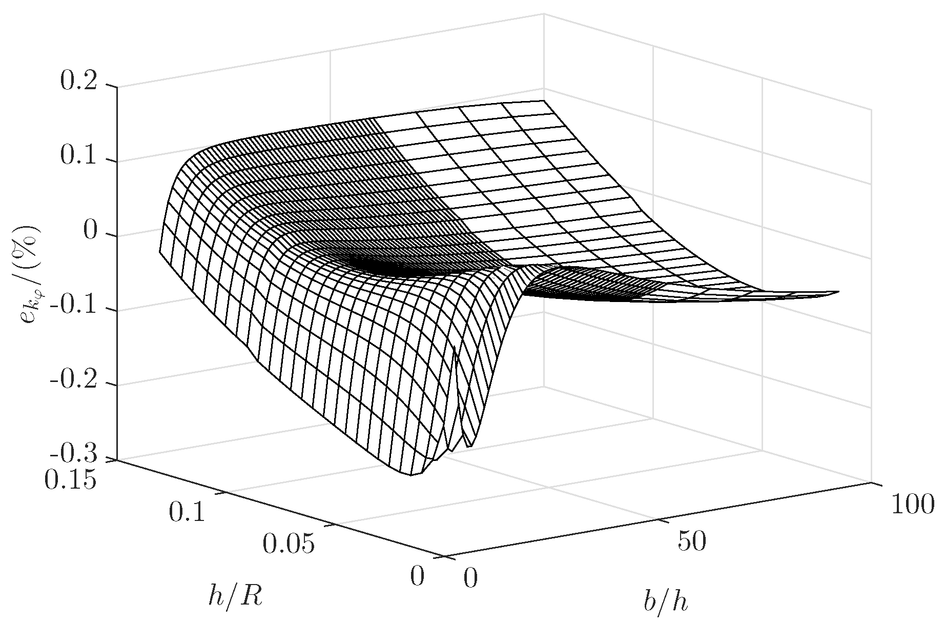
Using the two introduced correction factors
in Equation (6) and
in Equation (11), the deviation between the 3D-FE model and the analytical results of the equation of Paros and Weisbord [
12] is recalculated (see
Figure 10). The use of this approach provides a very good agreement with the results of the 3D-FE model for the presented geometry range shown with a maximum deviation of only 0.23%, which is much lower than that of the existing model equations. Thus, the correction factors can be used to correct other modeling equations based on the same assumptions, too (see
Table 1).
6. Verification of Results in Application Examples
To verify the accuracy of the presented approach, the corrected bending stiffness
is calculated using parameter values from semi-circular flexure hinges existing in the literature and compared to the bending stiffness
according to the 3D-FE model of
Section 3. Parameter values are presented in
Table 4. The values of the total height
H and total length
L used in the applications are not taken into account for the calculation but are rather selected to model a complete semi-circular contour. Since the values of material properties are not consistent among sources, the elastic constants
E and
are extracted from [
27]. The bending stiffness calculated using the equation by Paros and Weisbord [
12] (noted as
here) is also used for comparison. The relative stiffness deviation to the 3D-FE model results of the corrected bending stiffness and of the bending stiffness according to Paros and Weisbord [
12],
and
, respectively, are presented in
Table 5. Results show the significant reduction in the deviation, especially for the thinnest hinges. Even for values outside the range of application, the corrections factors still represent a very good alternative due to the conditions of their estimation.

 ,
, 


