Abstract
The demand of miniaturized, accurate and robust micro-tools for minimally invasive surgery or in general for micro-manipulation, has grown tremendously in recent years. To meet this need, a new-concept comb-driven microgripper was designed and fabricated. Two microgripper prototypes differing for both the number of links and the number of conjugate surface flexure hinges are presented. Their design takes advantage of an innovative concept based on the pseudo-rigid body model, while the study of microgripper mechanical potentialities in different configurations is supported by finite elements’ simulations. These microgrippers, realized by the deep reactive-ion etching technology, are intended as micro-tools for tissue or cell manipulation and for minimally invasive surgery; therefore, their biocompatibility in terms of protein fouling was assessed. Serum albumin dissolved in phosphate buffer was selected to mimic the physiological environment and its adsorption on microgrippers was measured. The presented microgrippers demonstrated having great potential as biomedical tools, showing a modest propensity to adsorb proteins, independently from the protein concentration and time of incubation.
1. Introduction
The demand for micro-manipulation in biomedical applications increased during the last decades. Hundreds of different micro-systems have indeed been reported in the literature [1,2], with different operational strategies [3] and being mainly dedicated to medical or biological applications. Among others, an untethered mobile microgripper controlled by an external electromagnetic coil system has been reported [4], where the manipulation of different microgels was successfully demonstrated with a pick-and-place robotic heterogeneous 3D assembly technique. A few more examples of microgrippers are present in the literature, piezoelectric [5,6] or thermally [7,8] or even magnetically actuated [8,9,10]. All these systems, however, present quite large dimensions and are not fully tested for working in a physiological environment, as required for biomedical applications.
The development of new microsystems and, in particular, silicon microgrippers for handling cells or tissues at the microscale was therefore pursued in this paper. Since such manipulators have to handle micro-objects, their size should be comparable to the size of the objects being manipulated. A real advantage of micro manipulation can be indeed achieved only if the manipulator is approximately as small as the sample to be manipulated. Starting from a first series of silicon micro-systems obtained by using a classical process based on Reactive-Ion Etching [11,12], a redesign was introduced here in order to fabricate more accurate, new-concept comb-driven microgripper prototypes using Deep Reactive-Ion Etching (DRIE) technology [13]. In this way, a widening in the microsystem design versatility and therefore in the range of potential applications was obtained.
Although the interest for biocompatibility has been widespread in the literature for years, this topic is less explored in relation to microsystems employed as micromanipulators in the biomedical field. In fact, there are few examples about a real use of microsystems for surgical purposes or for in situ biological tissues grasping [2]. Notably, none of these examples consider the possible side-effects such as protein fouling on microscale tools, which could adversely affect the outcome of surgical operations or biopsies. Among examples showing a use of microtools close to the real application, Gultepe et al. [14] report the ex vivo and in vivo tissue excision by microgrippers, which, however, were injected, visualized and recovered with standard equipment. Moreover, some examples of ex vivo micromanipulation in the physiological environment are reported in the literature—for example, the micro-scale compression of hydrogel microcapsules [15] or the micromanipulation of a micro blood vessel and a cyanobacteria cell [16]. The study of Micro Electro-Mechanical Systems (MEMS) microgripper for the deformability characterization of human red blood cells is also reported [17] as well as the study of MEMS tweezers for the viscoelastic characterization of soft materials, like tissues [18]. Besides silicon-based microgrippers, SU-8 microgrippers are reported for single cell manipulation in physiological solution [19]. All of these examples, however, do not consider the complexity of the in vivo environment, such as the presence of a relevant amount of circulating proteins.
In this context, the evaluation of protein adsorption on microdevices devoted to mini-invasive surgery or micromanipulation of cells and tissues could add value for predicting the in vivo performances of such devices. The adsorption of proteins such as albumin on different bulk materials like silicon or aluminum has indeed been reported in the literature (see, for example, [20,21,22]). Therefore, the study of protein fouling on microgripper surfaces could help in understanding if the delicate mechanism of microgrippers could be affected by the protein deposits that could be formed in physiological conditions. The issue of protein fouling is indeed well known in the field of silicon-based materials, and several authors reported on different methods to avoid protein fouling, as recently revised by Zhang et al. [23]. Among these methods, the functionalization with polyethyleneglycol and its derivatives are widely reported as well as the fabrication of surfaces with nano- or microtopographical features with anti-fouling properties [23].
This paper presents the design and fabrication process of silicon-based micro grippers. The design of microgrippers adopts an innovative concept based on the so-called pseudo–rigid body model (PRBM) [24], while their realization was achieved by the DRIE process. Furthermore, the biocompatibility of microgrippers was assessed in term of protein fouling. To this purpose, the most abundant protein present in blood (i.e., serum albumin) has been selected for the incubation with the developed devices in order to observe the microgripper behavior in a simplified environment similar to the in vivo conditions. For an easy visualization via confocal microscopy, fluorescently-labeled serum albumin was selected and tested at different protein concentrations and different time of incubation.
2. Material and Methods
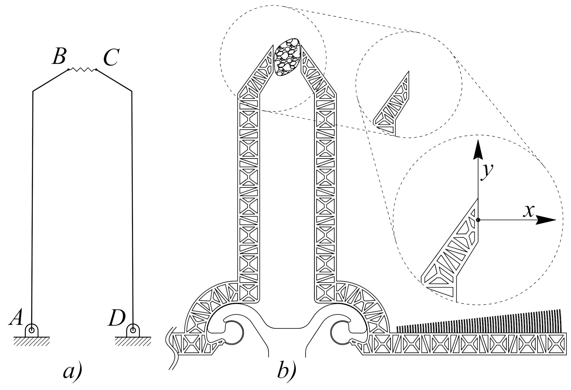
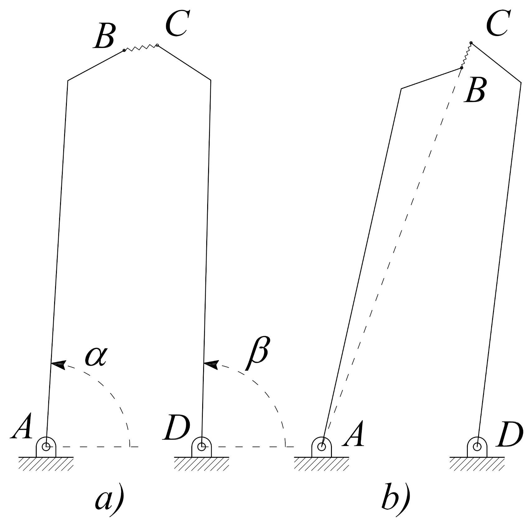
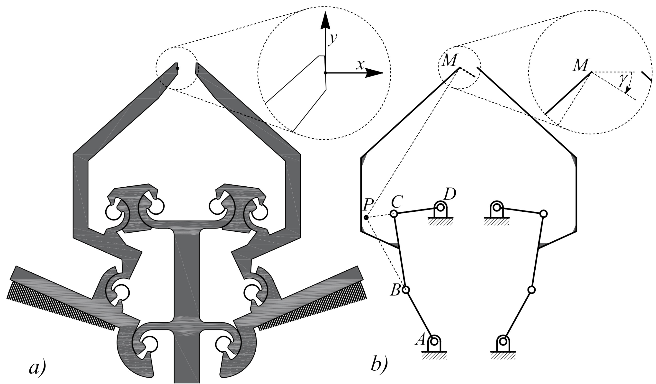
2.1. Design of Microgrippers
Two different types of microgrippers were designed and tested in this study, both realized by means of bulk microelectromechanical systems (MEMS) technology using silicon on insulator wafer substrates and deep reactive ion etching [13]. The design of the first prototype was developed using a scheme with two degrees of freedom and was inspired by the simplest rotating jaw system, as schematically reported in Figure 1. The PRBM, reported in Figure 1a), corresponds to the compliant structure illustrated in Figure 1b), where two flexure hinges have been introduced in place of the ordinary revolute pairs in A and D. In the figure, the reference system has also been introduced to monitor the motion of the jaw tip point. By using revolute joint-to-flexure substitution, any PRBM (Figure 1a) can be of inspiration to obtain an original compliant structure (Figure 1b). In the case under study, the left- and right-hand side jaws correspond to the rigid links and (of the ordinary linkage), which rotate around the fixed points A and D, respectively. When a tissue is grasped by the jaws ( in Figure 1), the overall scheme looks like a four-bar linkage whose coupler represents an elastic medium.
Figure 1.
Pseudo-rigid body model (a) and original structure (b) of the microgripper with two degrees of freedom.
There are several ways of designing a new compliant mechanism, with lumped compliance, starting from a functional representation. The motion of the compliant mechanism can be more or less approximated to the motion of the original ordinary mechanism, depending on the choice of the position of each flexure. In the present investigation, among the several possible ways to transform a functional into a compliant mechanism, two Conjugate Surface Flexure Hinges (CSFH) were the preferred choice to replace the two ordinary revolute joints in A and D. As a consequence, two pseudo–rigid substructures (jaws) were developed in place of the links and , and a new structure was first developed (see Figure 1b) and then fabricated (see Figure 2). This solution offers the advantage of a large relative rotation (up to using silicon), high accuracy and a reduction of the stress. The advantages of the CSFH rely on the fact that the center of the relative rotations are coincident with the center of the circular beam elastic weights. The microgripper represented in Figure 2 can be operated by finely controlling the torque exerted by the comb-drives, which are attached to the two jaws and . An accurate estimation of tissue stiffness can then be easily obtained [18].
Figure 2.
Scanning Electron Microscope (SEM) image of the first microgripper prototype, developed with the simple structure two joint-2 jaws and with two degrees of freedom (white solid lines and correspond to rigid links, which rotate around the fixed points A and D, respectively).
Considering the viscous behavior of the tissues, however, these microgripper designs, because of their simple structure and of the tissue compliance, can reach some critical configurations. This situation is shown in Figure 3a, where the link , representing the visco-elastic tissue, is not rigid anymore and could give rise to the critical configuration depicted in Figure 3b, where the points A, B and C are aligned. From this pose, any arbitrary rotation of link can not define a unique rotation because the link could be either rotated clockwise or counterclockwise. In this case, a more complicated control strategy should be applied and therefore a more complicated Application Specific Integrated Circuit (ASIC) is required.
Figure 3.
Pseudo-rigid body model of the microgripper with two degrees of freedom in an ordinary (a) and a critical (b) configuration.
As an alternative, a second generation of microgrippers was designed, based on a parallel structure in place of the simple structure with two joint-2 jaws, using a pair of symmetric four-bar linkages, as reported in Figure 4a. This microdevice handles the sample tissue with no intrinsic configuration, all critical configurations being avoided in the neighborhood of the working configuration.
Figure 4.
Planar layout (a) and functional scheme, PRBM model (b), of the second generation microgrippers with a pair of four-bar linkages , each one having four CSFHs and tip M attached to the coupler link . Point P represents the instantaneous rotation center for the coupler .
The functional design of the two symmetric four-bar linkages is illustrated in Figure 4b, where the coupler sustains the motion of the coupler point M. A prototype of such microdevice (Figure 5) was fabricated and tested. For clarity, the SEM image presented in Figure 5 also shows lines representing the pair of four-bar linkage and the coupler point M.
Figure 5.
SEM image of a microgripper belonging to the second generation (white solid lines represent two symmetric four-bar linkages, while point M is the coupler point).
Although this new structure is more complicated than the previous one, having a total of eight CSFHs, both jaws are guided as a rigid link by a loop-closed mechanism and therefore the microsystem has a parallel structure. Furthermore, the rotation center of each jaw is not a fixed point and can be positioned by arranging the mechanism initial configuration. As a consequence, the control strategy for this second microgripper prototype could be simplified with respect to the first prototype described above.
The two microgrippers, illustrated in Figure 2 and Figure 5, indeed have different characteristics and therefore both can be selected depending on whether the application requires a simple layout with limited elastic energy storage in the maximum compressed configuration or a more robust layout with an absence of critical configuration. For these two application cases, the single arm or the four bar linkage type would be the preferred structure, respectively.
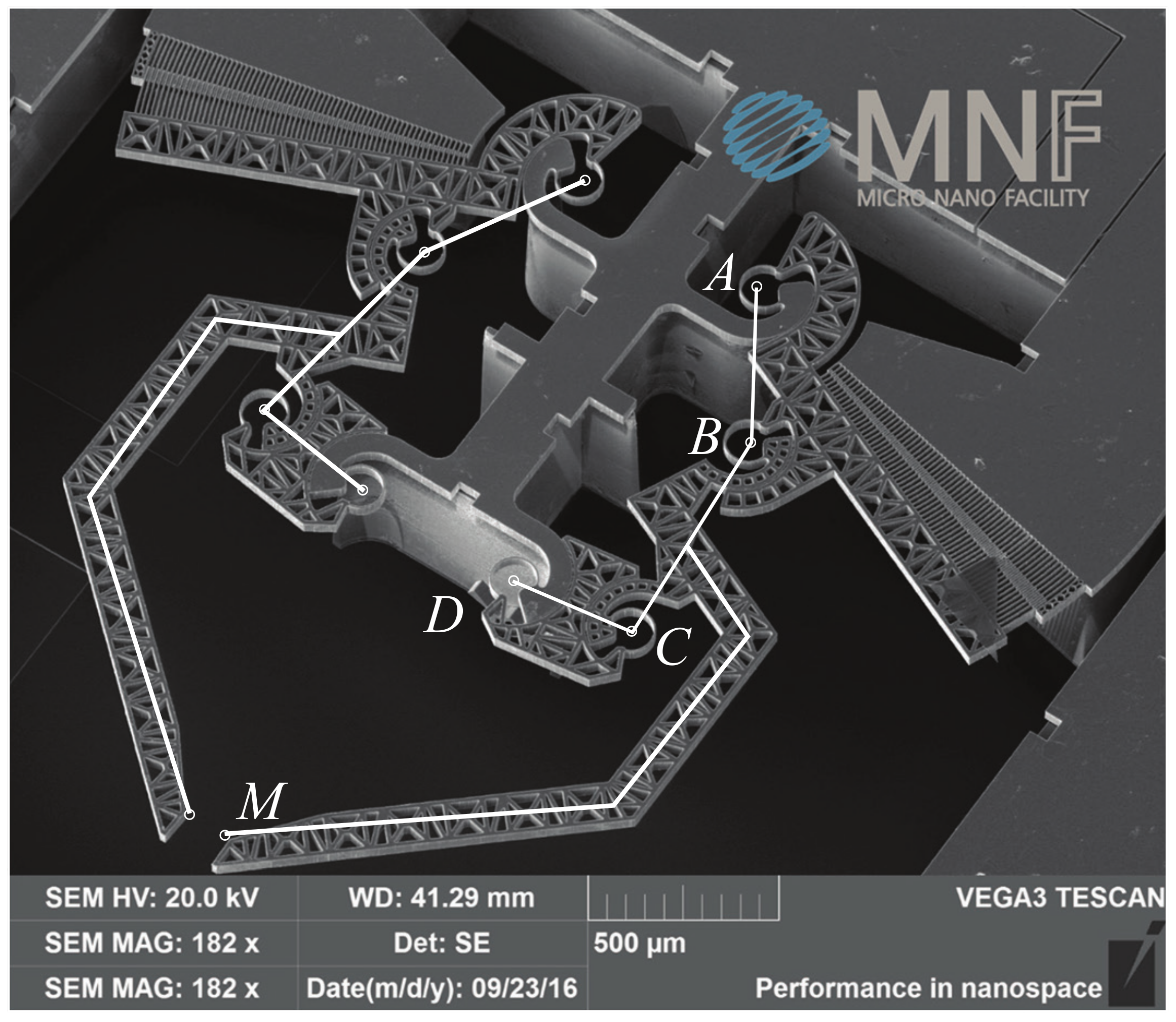
2.2. Fabrication of Microgrippers
Fabrication is performed on a 6-inch Semiconductor Equipment and Materials International (SEMI) standard silicon on insulator (SOI) wafers (SOI wafers supplied by SiMat, http://si-mat.com/). The wafer has a 500 m handle layer that will serve as a support layer for the rigid frames of the device. On top of it, a 40 m thick silicon layer is bonded and will provide the device layer, where all moving parts are patterned. A 2 m oxide layer is in between the two silicon layers, to be used as an etch stop when patterning the silicon and as a support before the complete release of the devices. Each side of the wafer will be patterned, etching the silicon down to the buried oxide layer using the Bosh DRIE process. The fabrication begins with the deposition of a multilayer mask to provide masking for DRIE etching on both sides. First, a 150 nm silicon oxide is deposited, followed by 200 nm Aluminum film sputtering and subsequent 100 nm Titanium sputtering. This layer stack is patterned using standard photolithography. An i-line stepper is used for the front side exposure, while a broadband mask aligner is used for the backside. The stack is then etched in IC standard plasma reactors. Once the masks are patterned, the silicon is etched with DRIE using Bosch patented process in an Alcatel SMS200 etcher (ALCATEL SMS, SPTS Technologies Ltd. Ringland Way, Newport, NP UK). The first etching is performed on the front side, 40 m deep, and then the second etch is performed on the wafer backside, 500 m deep. Now, the mechanical structure is fully patterned but still supported by the silicon oxide buried layer: this layer is removed by wet etching in hydrofluoric acid based solution to free the devices. In this step, all residual DRIE mask layers are etched as well. Last, an aluminum layer is formed by physical vapor deposition on the front side, in order to allow for electrical connections devoted to the electrostatic actuation. The details of the fabrication sequence as well as its development are reported in Bagolini et al. [13].
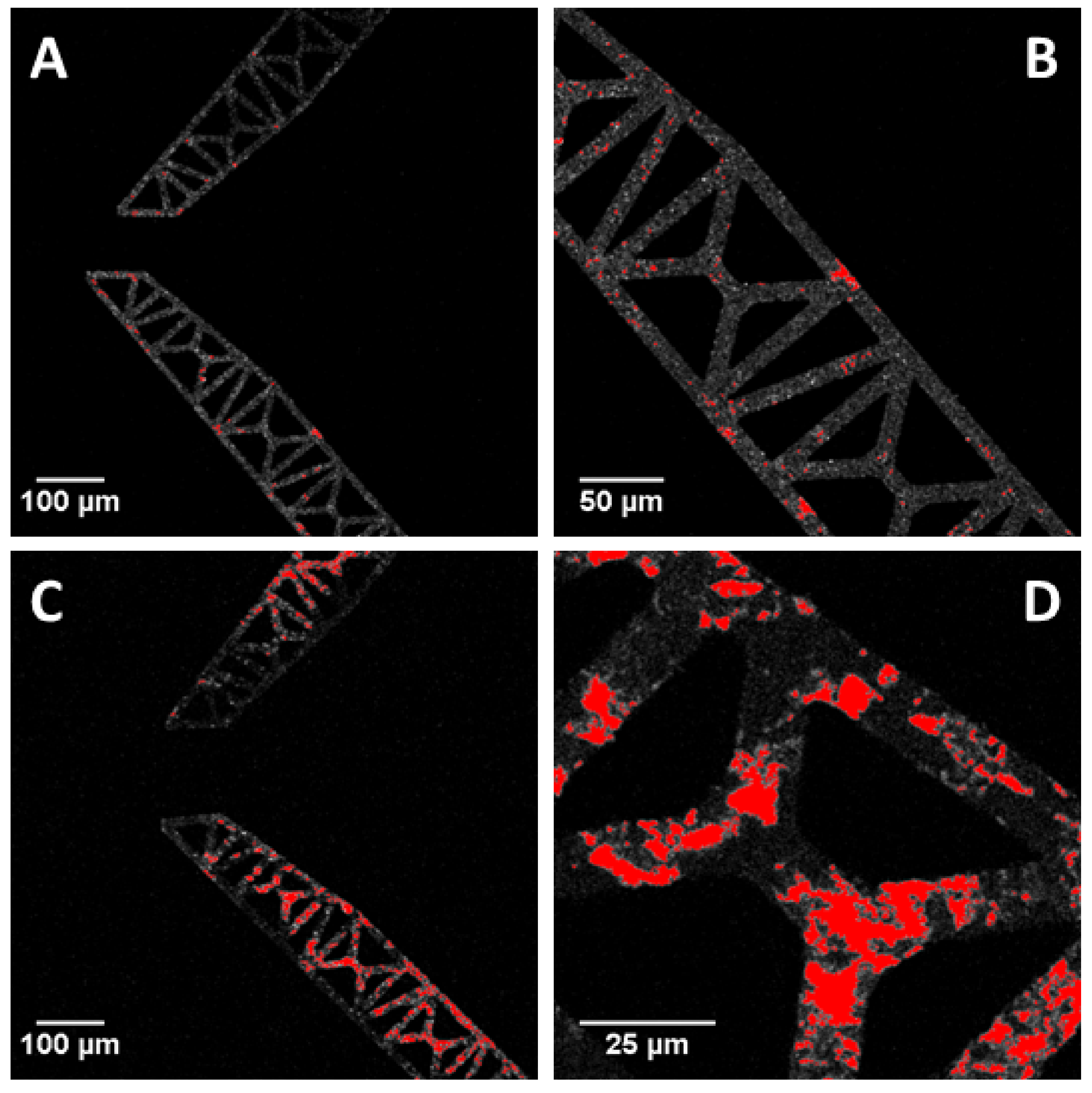
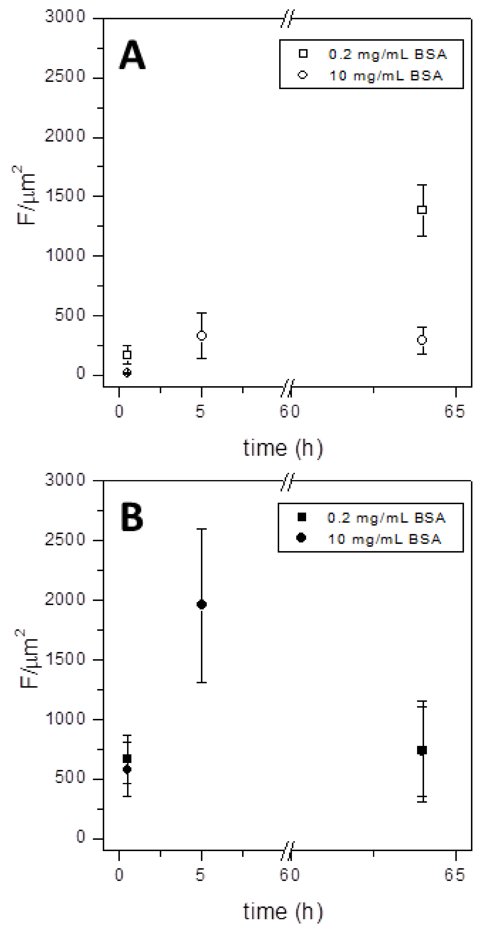
2.3. Protein Fouling Assessment
Protein fouling, i.e., the adsorption and aggregation of proteins on surfaces, was measured by incubating a fluorescent protein on microgrippers. Firstly, microgrippers were gently washed in ultrapure water and cleaned with an argon plasma (1 min, 6.8 W, 2 mbar) to remove organic contaminants. Microgrippers were next incubated with the desired concentration of protein (Albumin from Bovine Serum Tetramethylrhodamine conjugated, BSA-TAMRA, ThermoFisher Scientific, Waltham, MA USA) dissolved in a physiological buffer (DPBS, Sigma, St. Louis, MO USA) spanning different times of incubation. At the end of incubation, microgrippers were gently washed with ultrapure water to remove the excess of protein, dried in air and imaged at the confocal microscope Leica SP5-II (Leica Instruments, Wetzlar, Germany), using an Argon (514 nm) laser line for excitation. All samples were observed utilizing a 20× magnification objective and analyzed with the ImageJ software (version 1.51, Bethesda, MD USA, http://imagej.nih.gov/ij) [25]. Both images and emission spectra (from 520 nm to 650 nm with a step of 5 nm) were acquired.
3. Results and Discussion
The microgrippers presented here were carefully designed and studied for their mechanical potentialities, also simulating their response in different configurations. Two prototypes of microgrippers were realized and investigated. They differ in terms of both number of links and number of CSFHs. The first microgripper is composed of two links and two CSFHs, while the latter is more complex, having a pair of four-bar linkages and eight CSFHs. This last solution allows a more efficient mechanical action, avoiding the critical configurations that can be reached by the first type of microgrippers. Both prototypes were fabricated and tested for their biocompatibility in terms of protein fouling, as a first step to evaluate their possible use as biomedical devices.
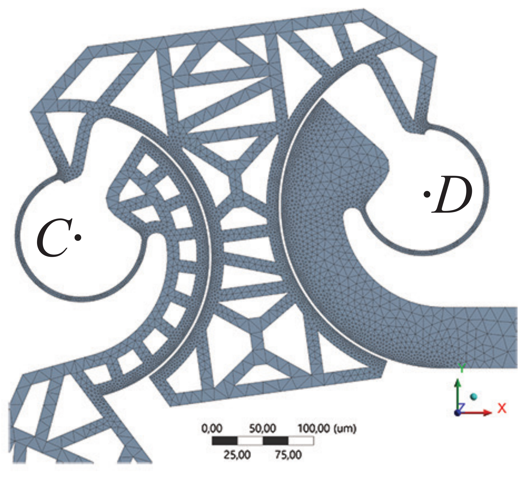
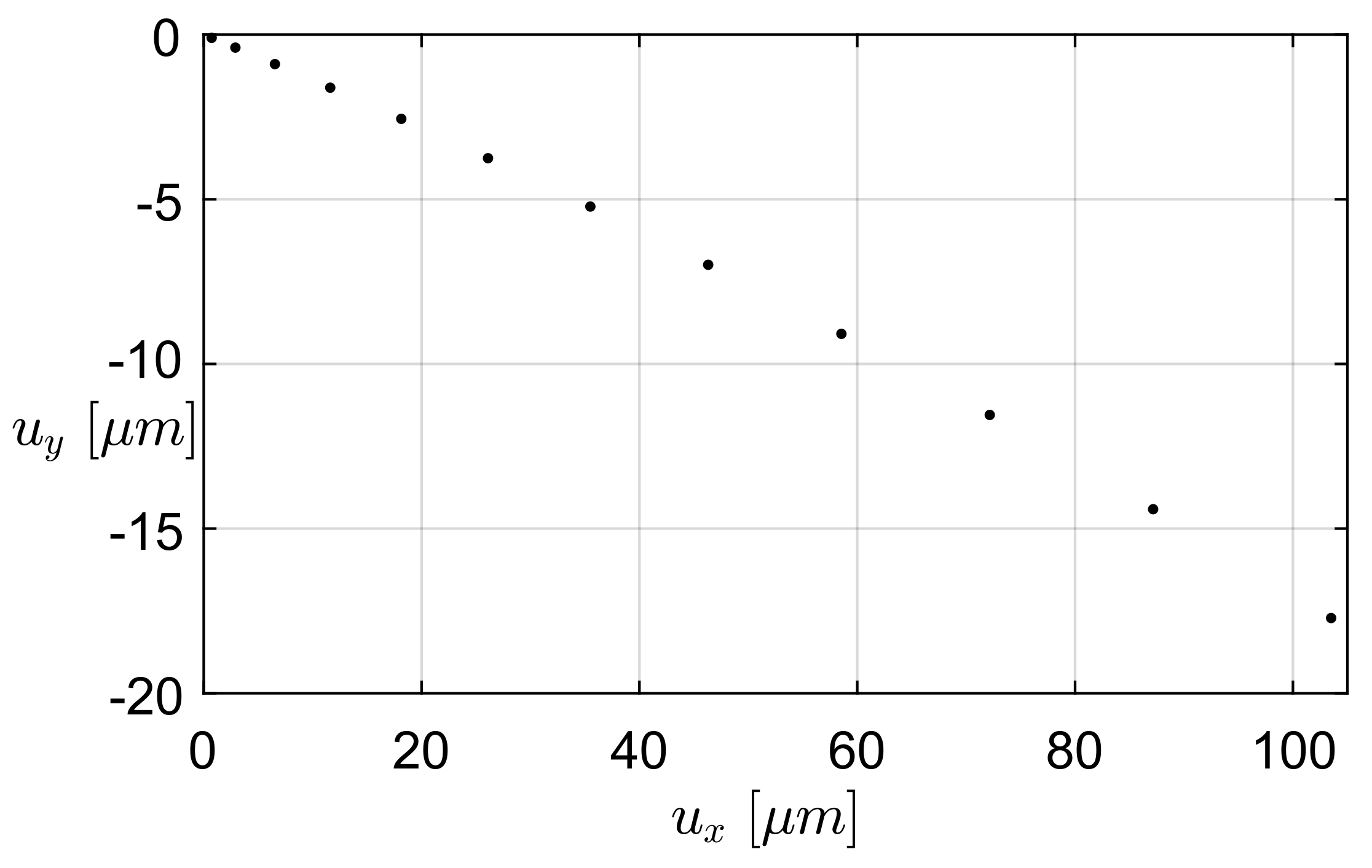
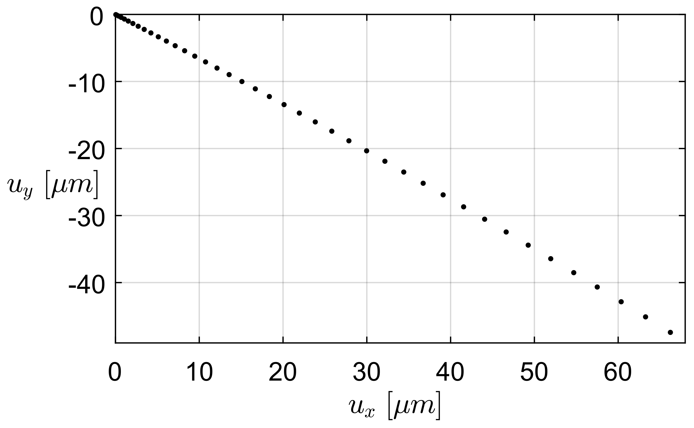
3.1. Finite Elements Simulation
Finite Elements Analysis (FEA) simulations were performed to evaluate the static response through electrostatic actuation of the microgrippers by using the commercial Finite Elements Analysis package ANSYS [26]. The rotary comb-drive action was modeled as a series of forces f acting perpendicularly to the free-end section of the movable fingers, each force having magnitude equal to that described in [27]:
where is the dielectric constant of the air, V is the applied electric potential difference, g is the radial gap between the fingers, and h is the finger thickness. The common center of the arcs defining the fingers was positioned on the centroid of the flexible element, which is also a limit position for the center of rotation of the flexible element [28]. The design parameters of the comb-drive actuator are listed in Table 1, together with the geometric parameters of the constant-curvature flexure. Multi-step analyses were performed, by increasing the applied voltage with steps of 5 V, from 5 V to the tension corresponding to the maximum angular stroke of the comb-drive, i.e., 4.5 and 5° for the one-link and for the four-bars, respectively. Nonlinearity due to large deflections was considered in the analysis setup, and the anisotropic formulation of elasticity for silicon was considered as described in Hopcroft et al. [29]. The generated meshes were properly refined in the flexible elements and in the fingers of the comb-drives. A detail of one of the generated meshes, corresponding to the four-bars microgripper, is shown in Figure 6.
Table 1.
Geometric parameters of comb-drive and flexures.
Figure 6.
Detail of the refined mesh in two flexures, corresponding to the four-bars microgripper. Letters C and D refer to the same letters and structures presented in Figure 5.
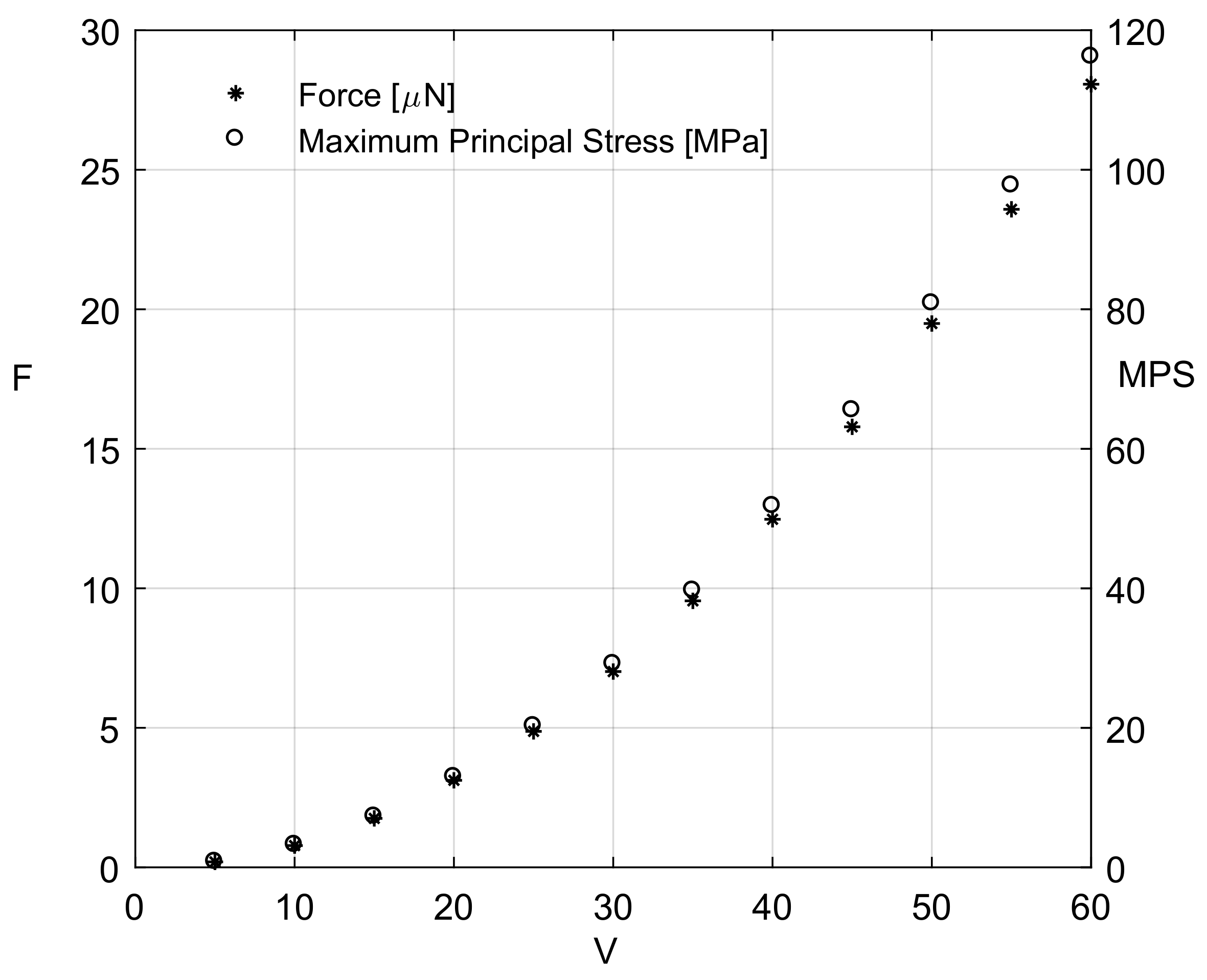
3.1.1. FEA Simulation of One-Link Microgripper
Microgripper behaviour was simulated through the finite elements analysis, as described in Section 3.1, in order to study their mechanic and kinematic properties for the future use as biomedical microdevices.
For the first prototype, i.e., the one-link microgripper (Figure 2), the generated mesh was composed of 14,401 nodes and 10,563 elements. The maximum angular stroke (4.0°) was reported at the force f = 28 N, corresponding to an applied voltage of 60 V. Figure 7 reports, with respect to the applied electric potential difference, the values of the force exerted by each comb drive and the maximum values of the maximum principal stress (MPS) distribution, determined by means of Equation (1) and FEA, respectively. The maximum value of the MPS is equal to 116 MPa, i.e., below the yield strength of a single-crystal silicon [30]. The path followed by the microgripper tip is depicted in Figure 8. The displacement corresponding to the last simulation step is equal to 103.5 m along the x-axis and to 17.7 m along the y-axis.
Figure 7.
One-link microgripper: force magnitudes exerted by each comb drive and maximum values of the Maximum Principal Stress (MPS) as a function of the applied electric potential difference.
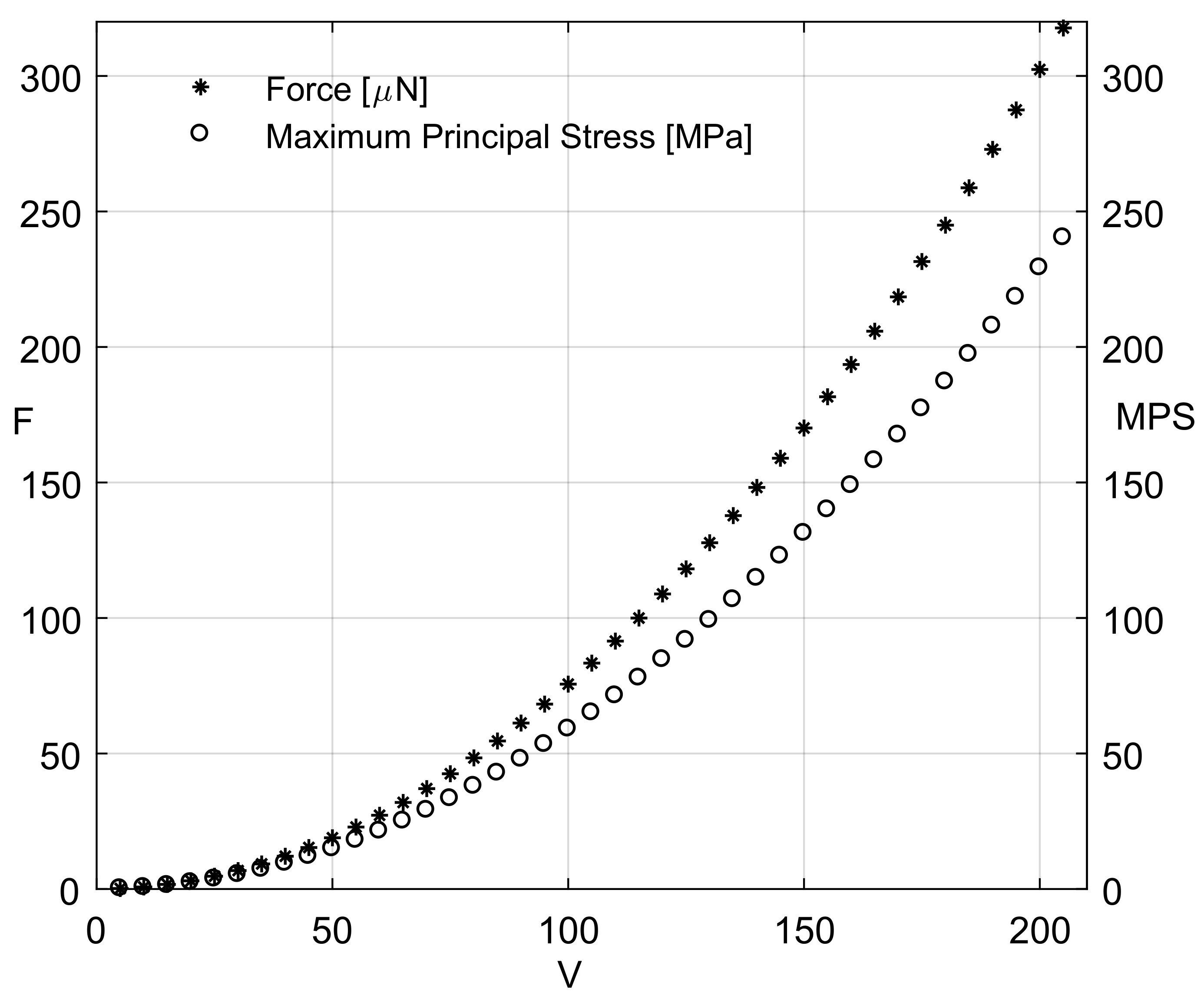
3.1.2. FEA Simulation of Four-Bar Microgrippers
In the case of the second prototype, i.e., the four-bar microgripper (Figure 5), the generated mesh was composed of 23,345 nodes and 34,990 elements. The maximum angular stroke (4.9°) occurred for f = 317 N, corresponding to 205 V. Figure 9 reports the values of the exerted force and the MPS distribution. Interestingly, the maximum MPS value is equal to 240 MPa, i.e., below the yield strength of a single-crystal silicon, as already observed for the one-bar microgripper.
Figure 9.
Four-bar microgripper: force magnitudes exerted by each comb drive and maximum values of the MPS as a function of the applied electric potential difference.
The path followed by the microgripper tip is depicted in Figure 10. The displacement corresponding to the last simulation step is equal to 66.2 m along the x-axis and to 47.4 m along the y-axis. The simulation of the tip path is particularly important in the case of the four-bar linkage. Considering Figure 4b, the angle of inclination of the tangent of the path of the tip point M, in the undeformed configuration, could be easily measured, as evident from the PRBM four-bar linkage. As is already known, angle is coincident with the inclination angle of the velocity of point M. Therefore, once the center P is identified of instantaneous rotation of the coupler (as made evident in Figure 4b), , and thus the path tangent in M, must be orthogonal to the line PM. While geometry of the PRBM yields a value of , Figure 10 shows that the simulated path is tangent to an inclination varying from (at the undeformed initial configuration) to (at the limit position), with a negligible discrepancy both at the beginning and at the extreme position of the path. The two analyses performed for the simulation of microgripper behaviour, i.e., PRBM and FEA, are therefore in good agreement and lead to the conclusion that the method based on the analysis of the PRBM can be successfully employed to design new gripper layouts. This allows designers to conceive new microgrippers that could successfully be employed as biomedical tools for tissue manipulation or for minimally invasive surgery.
Figure 10.
Tip path followed by the four-bar microgripper along the x- and y-axes (see the Reference system represented in Figure 4a).
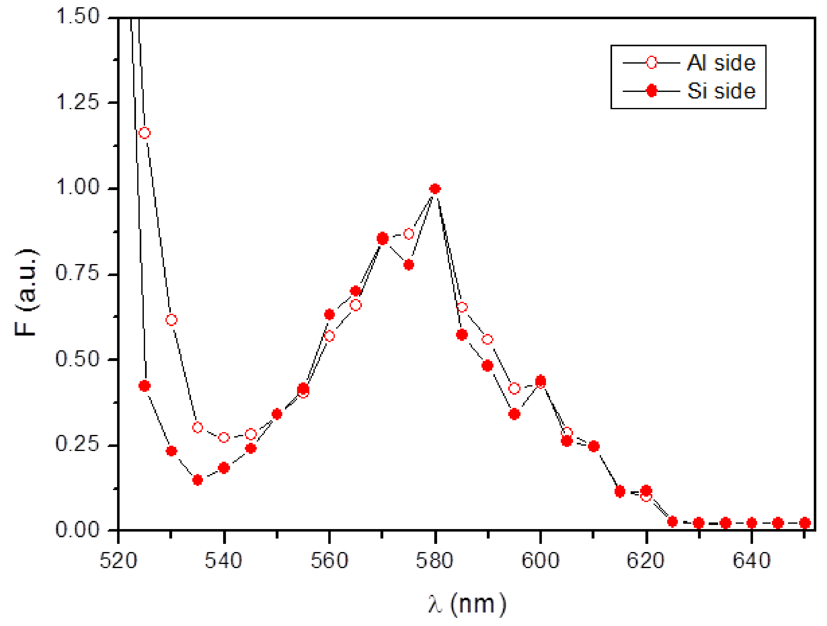
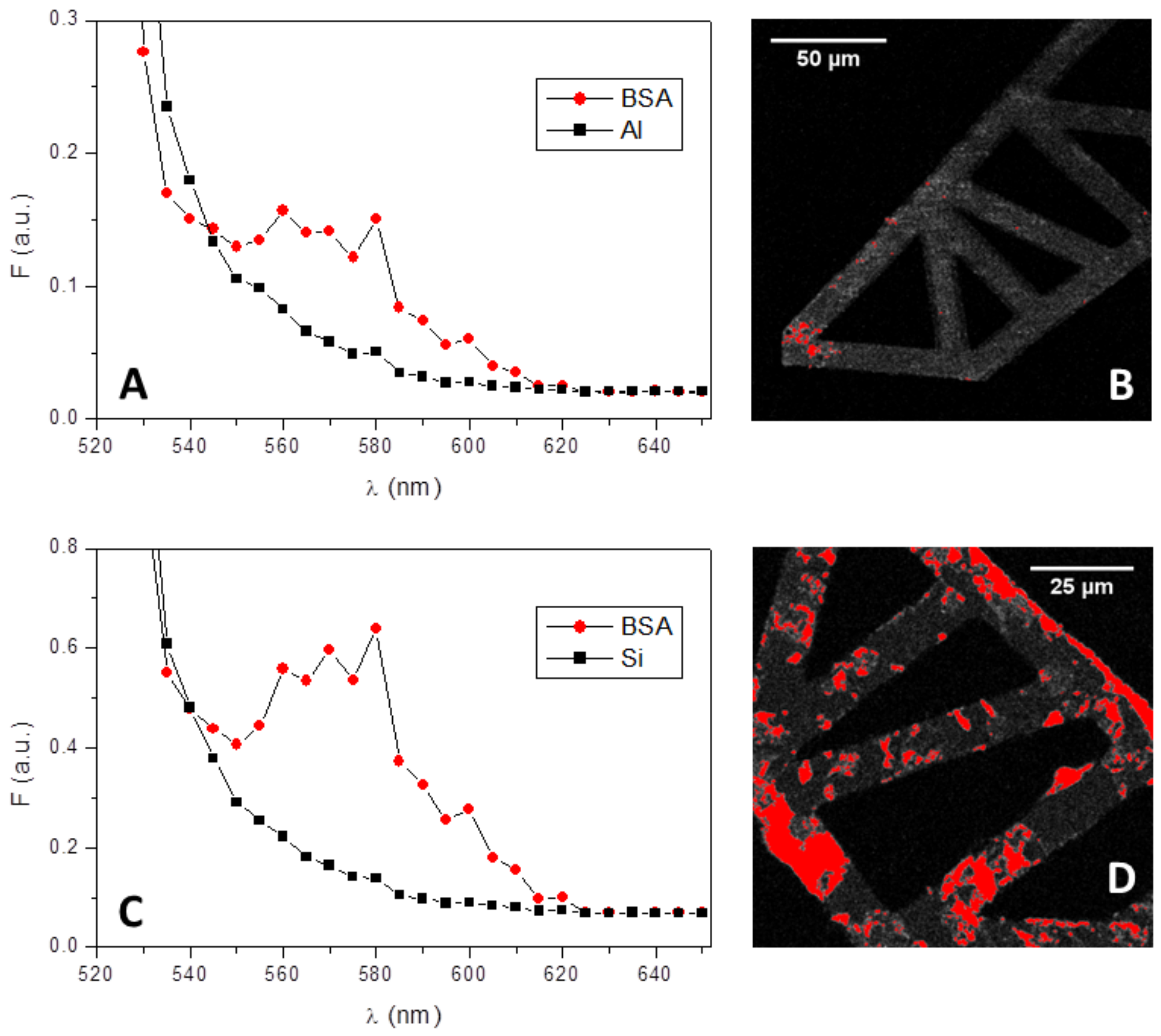
3.2. Protein Fouling at the Microgripper Surfaces
Once the good suitability of microgrippers from the mechanic and kinematic point of view is assessed, their compatibility with the use in microsurgery was also investigated. To test the protein propensity to aspecifically aggregate on microgripper surfaces, possibly impeding their correct movements, a test based on protein incubation was selected. The main problem when external objects such as surgical instruments contact body organs or tissues is indeed the adsorption of proteins on such objects [31]. Proteins can easily be adsorbed on external objects, acting as nucleation centers for other materials such as platelets, cells, and bacteria, finally originating a phenomenon known as fouling. The intensity of this phenomenon depends on several parameters, such as the time of contact and the type of surface material. Objects in the microscale range, and in particular their moving parts, could be easily coated by several layers of proteins with the final result of hindering the correct movement of these microdevices. Therefore, the assessment of biocompatibility in terms of protein fouling seems essential for the future use of microgrippers for biomedical applications. Among proteins, serum albumin is the most abundant in human blood, accounting for more than 50% of total proteins [32,33]. The presence of albumin in the extravascular compartment is also significant.
Here, a solution of albumin dissolved in physiological buffer (i.e., DPBS) was selected to mimic the physiological conditions of salts and biomolecules as a simplified but still representative environment. When microgrippers are applied as microtools for picking up tissues for biopsies or as micromanipulators of cultured cells for research purposes, they are in a physiological environment for a non-negligible period of time. During this period, several biological reactions could occur, for example platelet adhesion and activation leading to blood clotting could occur when microgrippers are in contact with blood, or, in the simplest case, proteins could be deposited on the microgripper surface, possibly clogging its delicate mechanisms of motion.
To evaluate the possible effects of protein fouling on microgrippers, the adsorption of different concentrations of a fluorescently-labelled albumin, i.e., BSA-TAMRA, was monitored in time via confocal microscopy. Both sides of microgrippers were observed, since they differ for the external material layer, i.e., silicon or aluminum. The presence of BSA was therefore quantified on both sides in terms of fluorescence intensity per surface area for all the experimental conditions tested. Moreover, both microgripper prototypes were treated and considered in the same way, since the fabrication process was the same as well as microgripper surfaces, i.e., the parts that are in contact with the physiological environment. Considering protein adsorption, the presence of albumin after 30 min incubation was modest on the aluminum side of microgrippers (see Figure 11, panels A and B), while resulting as more evident on the silicon side, as shown in panels C and D of the same figure.
Figure 11.
Images of BSA-TAMRA (red regions) adsorbed on the aluminum side of microgrippers (A and B) or on the silicon side of microgrippers (C and D), presented with different magnifications. BSA was incubated for 30 min at 0.2 mg/mL, at room temperature. Microgrippers are highlighted in gray.
The same behaviour was observed also after 5 h of BSA incubation, i.e., albumin adsorption was more evident on the silicon side than on the aluminum side (Figure 12, panels B and D). Moreover, the signal acquired on both surfaces was checked for its specificity by measuring the fluorescence spectra on different areas of the images. A clear fluorescence peak corresponding to the maximum emission wavelength of TAMRA (i.e., 580 nm) was always detected from the data corresponding to the red areas (circles in panels A and C of Figure 12), confirming the adsorption of albumin. This conclusion was reinforced by the spectral data taken on the gray areas of the microgrippers (squares in panels A and C of Figure 12), which did not present any specific peak in the fluorescence spectra.
Figure 12.
Fluorescence spectra and images of BSA-TAMRA adsorbed on the aluminum side (A and B) and on the silicon side (C and D) of microgrippers. In addition, 10 mg/mL of BSA-TAMRA were incubated at room temperature for 5 h separately on both microgrippers’ sides. Spectra were acquired where the fluorescence signal was higher (i.e., on the red areas, B and D) and outside these areas but on microgrippers (gray structures, b and d), giving, respectively, the red circles’ curves and the black squares’ curves of A and C.
Furthermore, when the emission spectra measured on the two sides of microgrippers were superimposed (Figure 13), exactly the same shape was observed, indicating once more the presence of BSA on both microgrippers’ sides.
Figure 13.
Fluorescence emission spectra measured either on the aluminum side (open circles) or on the silicon side (solid circles) of microgrippers. Spectra were taken on microgrippers treated for 64 h with 0.2 mg/mL BSA-TAMRA at room temperature. Fluorescence intensities are normalized to the maximum wavelength, i.e., 580 nm.
BSA adsorption was also measured as a function of time and concentration (Figure 14). Increasing concentrations of BSA-TAMRA did not significantly alter protein adsorption, which resulted similarly when 0.2 or 10 mg/mL BSA-TAMRA were incubated on both sides of the microgrippers. The adsorption kinetic, however, was faster on the silicon side (panel B, Figure 14) with respect to the aluminum side (panel A, Figure 14). The amount of BSA was indeed higher on silicon even after 30 min incubation, quickly increasing after 5 h incubation. On the contrary, a long-term incubation of 64 h did not result in a broader protein coating, the two microgripper sides being similar in terms of BSA adsorption. The permanence of microgrippers in contact with biological fluids can reasonably be considered in the range from minutes to a few hours: here, a long incubation time (i.e., 64 h) was included in order to stress the conditions leading to protein fouling and fully characterize the biocompatible behavior of microgrippers in view of their future usage in medicine or research.
Figure 14.
BSA-TAMRA adsorption on the aluminum side (A) and the silicon side (B) of microgrippers. Adsorption is shown as fluorescence intensity per area unit. Two different concentrations of BSA were incubated, i.e., 0.2 mg/mL (squares) and 10 mg /mL (circles), for 30 min, 5 h or 64 h at room temperature.
Interestingly, a complete protein adsorption has never been observed, neither after the long-term incubation nor at higher BSA concentration. The BSA coating was indeed inhomogeneous also on the silicon side after short incubation time, as witnessed in images of Figure 11 and Figure 12. In other words, microgrippers present a modest propensity to adsorb proteins on both sides. Moreover, this adsorption seems independent of the protein concentration or time of incubation. This property is crucial for microgripper medical applications, such as in mini-invasive surgery, where the clogging mediated by proteins is a non-negligible risk.
4. Conclusions
The complete development of two microgripper prototypes for biomedical applications, fabricated with the MEMS technology and equipped with CSFH, is discussed in detail. In particular, the full process is presented, including the design, the simulation, fabrication, and, finally, the biocompatibility assessment.
The version of the device prototypes presented here has an overall size of about 2 mm × 2 mm, which still seems quite huge in comparison with the objects to be manipulated, such as cells. These dimensions, however, could be easily miniaturized to 1 mm × 1 mm, with the real opportunity of developing a professional inspecting instrument for laboratory measurements, surgical endoscopic operations, or diagnosis of cell or tissue deterioration. Furthermore, by adjusting some process parameters, the overall size can be further reduced to 0.5 mm, including ASIC chips, opening up the possibility to employing these minimally-invasive microgrippers for in vivo applications. All of the described stages gave very positive results, which lead to the conclusion that the two presented microgripper designs have great potential and feasibility for biomedical applications. Experiments to test, for example, the gripping force or displacement at the microgripper tip in the presence of proteins and in the physiological environment are planned to reinforce the conclusions of this study also in working conditions. Experiments like these could define the limit amount of proteins tolerated for microgripper movements or the need for an antifouling treatment before their final use in biomedical applications.
In this context, the good biocompatibility observed in terms of protein fouling plays a crucial role in paving the way to a functional use of microgrippers in mini-surgery or for cell and tissue manipulation for both clinical and research purposes.
Author Contributions
Although the paper is the result of genuine cooperative work, the following specific contributions can be stated. C.Potrich, L.Lunelli and C.Pederzolli performed biocompatibility assay and data interpretation; A.Bagolini and P.Bellutti fabricated microdevices; M.Verrotti and N.P.Belfiore designed microdevices and performed the PRBM and FEA analysis. All authors contributed in manuscript writing and figures drawing.
Conflicts of Interest
The authors declare no conflicts of interest.
Abbreviations
| ASIC | Application Specific Integrated Circuit |
| CSFH | Conjugate Surface Flexure Hinge |
| DPBS | Dulbecco’s Phosphate-Buffered Saline |
| DRIE | Deep Reactive-Ion Etching |
| FEA | Finite Elements Analysis |
| MEMS | Micro Electro-Mechanical Systems |
| MPS | Maximum Principal Stress |
| PRBM | Pseudo-Rigid Body Model |
| SEM | Scanning Electron Microscope |
References
- Verotti, M.; Dochshanov, A.; Belfiore, N.P. A comprehensive survey on microgrippers design: Mechanical structure. J. Mech. Des. 2017, 139, 060801. [Google Scholar] [CrossRef]
- Tai, K.; El-Sayed, A.R.; Shahriari, M.; Biglarbegian, M.; Mahmud, S. State of the art robotic grippers and applications. Robotics 2016, 5, 11. [Google Scholar] [CrossRef]
- Dochshanov, A.; Verotti, M.; Belfiore, N.P. A comprehensive survey on microgrippers design: Operational strategy. J. Mech. Des. 2017, 139, 070801. [Google Scholar] [CrossRef]
- Chung, S.E.; Dong, X.; Sitti, M. Three-dimensional heterogeneous assembly of coded microgels using an untethered mobile microgripper. Lab on a Chip 2015, 15, 1667–1676. [Google Scholar] [CrossRef] [PubMed]
- Chen, W.; Zhang, X.; Fatikow, S. A novel microgripper hybrid driven by a piezoelectric stack actuator and piezoelectric cantilever actuators. Rev. Sci. Instrum. 2016, 87, 115003. [Google Scholar] [CrossRef] [PubMed]
- El-Sayed, A.M.; Abo-Ismail, A.; El-Melegy, M.T.; Hamzaid, N.A.; Osman, N.A.A. Development of a Micro-Gripper Using Piezoelectric Bimorphs. Sensors 2013, 13, 5826–5840. [Google Scholar] [CrossRef] [PubMed]
- Daunton, R.; Gallant, A.; Wood, D.; Kataky, R. A thermally actuated microgripper as an electrochemical sensor with the ability to manipulate single cells. Chem. Commun. 2011, 47, 6446–6448. [Google Scholar] [CrossRef] [PubMed]
- Ongaro, F.; Scheggi, S.; Yoon, C.; Van den Brink, F.; Oh, S.H.; Gracias, D.H.; Misra, S. Autonomous planning and control of soft untethered grippers in unstructured environments. J. Micro-Bio Rob. 2017, 12, 45–52. [Google Scholar] [CrossRef] [PubMed]
- Ger, T.R.; Huang, H.T.; Chen, W.Y.; Lai, M.F. Magnetically-controllable zigzag structures as cell microgripper. Lab on a Chip 2013, 13, 2364–2369. [Google Scholar] [CrossRef] [PubMed]
- Al Mashagbeh, M.; Al-Dulaimi, T.; Khamesee, M.B. Design and optimization of a novel magnetically-actuated micromanipulator. Microsyst. Technol. 2017, 23, 3589–3600. [Google Scholar] [CrossRef]
- Balucani, M.; Belfiore, N.P.; Crescenzi, R.; Verotti, M. The development of a MEMS/NEMS-based 3 D.O.F. compliant micro robot. Int. J. Mech. Control 2011, 12, 3–10. [Google Scholar]
- Belfiore, N.; Broggiato, G.; Verotti, M.; Balucani, M.; Crescenzi, R.; Bagolini, A.; Bellutti, P.; Boscardin, M. Simulation and Construction of a MEMS CSFH Based Microgripper. Int. J. Mech. Control 2015, 16, 21–30. [Google Scholar]
- Bagolini, A.; Ronchin, S.; Bellutti, P.; Chistè, M.; Verotti, M.; Belfiore, N.P. Fabrication of Novel MEMS Microgrippers by Deep Reactive Ion Etching With Metal Hard Mask. J. Microelectromech. Syst. 2017, 26, 926–934. [Google Scholar] [CrossRef]
- Gultepe, E.; Randhawa, J.S.; Kadam, S.; Yamanaka, S.; Selaru, F.M.; Shin, E.J.; Kalloo, A.N.; Gracias, D.H. Biopsy with Thermally-Responsive Untethered Microtools. Adv. Mater. 2013, 25, 514–519. [Google Scholar] [CrossRef] [PubMed]
- Kim, K.; Liu, X.; Zhang, Y.; Cheng, J.; Wu, X.Y.; Sun, Y. Elastic and viscoelastic characterization of microcapsules for drug delivery using a force-feedback MEMS microgripper. Biomed. Microdevices 2009, 11, 421–427. [Google Scholar] [CrossRef] [PubMed]
- Zhang, R.; Chu, J.; Wang, H.; Chen, Z. A multipurpose electrothermal microgripper for biological micro-manipulation. Microsyst. Technol. 2013, 19, 89–97. [Google Scholar] [CrossRef]
- Cauchi, M.; Grech, I.; Mallia, B.; Mollicone, P.; Sammut, N. Analytical, Numerical and Experimental Study of a Horizontal Electrothermal MEMS Microgripper for the Deformability Characterisation of Human Red Blood Cells. Micromachines 2018, 9, 108. [Google Scholar] [CrossRef]
- Di Giamberardino, P.; Bagolini, A.; Bellutti, P.; Rudas, I.J.; Verotti, M.; Botta, F.; Belfiore, N.P. New MEMS Tweezers for the Viscoelastic Characterization of Soft Materials at the Microscale. Micromachines 2017, 9, 15. [Google Scholar] [CrossRef]
- Chronis, N.; Lee, L.P. Electrothermally activated SU-8 microgripper for single cell manipulation in solution. J. Microelectromech. Syst. 2005, 14, 857–863. [Google Scholar] [CrossRef]
- Filali, L.; Brahmi, Y.; Sib, J.D.; Bouhekka, A.; Benlakehal, D.; Bouizem, Y.; Kebab, A.; Chahed, L. The effect of amorphous silicon surface hydrogenation on morphology, wettability and its implication on the adsorption of proteins. Appl. Surf. Sci. 2016, 384, 107–115. [Google Scholar] [CrossRef]
- Givens, B.E.; Diklich, N.D.; Fiegel, J.; Grassian, V.H. Adsorption of bovine serum albumin on silicon dioxide nanoparticles: Impact of pH on nanoparticle-protein interactions. Biointerphases 2017, 12, 02D404. [Google Scholar] [CrossRef] [PubMed]
- Fukuzaki, S.; Urano, H.; Nagata, K. Adsorption of bovine serum albumin onto metal oxide surfaces. J. Ferment. Bioeng. 1996, 81, 163–167. [Google Scholar] [CrossRef]
- Zhang, X.; Brodus, D.; Hollimon, V.; Hu, H. A brief review of recent developments in the designs that prevent bio-fouling on silicon and silicon-based materials. Chem. Cent. J. 2017, 11, 18. [Google Scholar] [CrossRef] [PubMed]
- Howell, L.; Magleby, S.; Olsen, B. Handbook of Compliant Mechanisms; John Wiley and Sons: Hoboken, NJ, USA, 2013. [Google Scholar]
- Schindelin, J.; Arganda-Carreras, I.; Frise, E.; Kaynig, V.; Longair, M.; Pietzsch, T.; Preibisch, S.; Rueden, C.; Saalfeld, S.; Schmid, B.; et al. FIJI: An open-source platformfor biological-image analysis. Nat. Methods 2012, 9, 676–682. [Google Scholar] [CrossRef] [PubMed]
- ANSYS Inc. 2017. Available online: http://www.ansys.com (accessed on 27 July 2017).
- Yeh, J.A.; Chen, C.N.; Lui, Y.S. Large rotation actuated by in-plane rotary comb-drives with serpentine spring suspension. J. Micromech. Microeng. 2004, 15, 201–206. [Google Scholar] [CrossRef]
- Verotti, M. Analysis of the center of rotation in primitive flexures: Uniform cantilever beams with constant curvature. Mech. Mach.Theory 2016, 97, 29–50. [Google Scholar] [CrossRef]
- Hopcroft, M.A.; Nix, W.D.; Kenny, T.W. What is the Young’s Modulus of Silicon? J. Microelectromech. Syst. 2010, 19, 229–238. [Google Scholar] [CrossRef]
- Petersen, K.E. Silicon as a mechanical material. Proc. IEEE 1982, 70, 420–457. [Google Scholar] [CrossRef]
- Anand, G.; Zhang, F.; Linhardt, R.J.; Belfort, G. Protein-Associated Water and Secondary Structure Effect Removal of Blood Proteins from Metallic Substrates. Langmuir 2011, 27, 1830–1836. [Google Scholar] [CrossRef] [PubMed]
- Raoufinia, R.; Mota, A.; Keyhanvar, N.; Safari, F.; Shamekhi, S.; Abdolalizadeh, J. Overview of Albumin and Its Purification Methods. Adv. Pharm. Bull. 2016, 6, 495–507. [Google Scholar] [CrossRef] [PubMed]
- Kumar, D.; Banerjee, D. Methods of albumin estimation in clinical biochemistry: Past, present, and future. Clin. Chim. Acta 2017, 469, 150–160. [Google Scholar] [CrossRef] [PubMed]
© 2018 by the authors. Licensee MDPI, Basel, Switzerland. This article is an open access article distributed under the terms and conditions of the Creative Commons Attribution (CC BY) license (http://creativecommons.org/licenses/by/4.0/).