Article

A Pump-Controlled Circuit for Single-Rod Cylinders that Incorporates Limited Throttling Compensating Valves

Fluid Power & Telerobotics Research Laboratory, Department of Mechanical Engineering, University of Manitoba, Winnipeg, MB R3T5V6, Canada
*
Authors to whom correspondence should be addressed.
Actuators 2018, 7(2), 13; https://doi.org/10.3390/act7020013
Submission received: 26 February 2018 / Revised: 19 March 2018 / Accepted: 23 March 2018 / Published: 27 March 2018

Abstract

:
Valve-controlled hydraulic actuation systems are favored in many applications due to their fast response, high power-to-weight ratio, and stability under variable working conditions. Efficiency, however, is the main disadvantage of these systems. Pump-controlled hydraulic actuations, on the other hand, eliminate energy losses in throttling valves and require less cooling. Furthermore, they inherently hold the ability to recover energy from assistive loads. Pump-controlled circuits for double-rod cylinders are well developed and are implemented in many industrial applications, including aviation. However, pump-controlled circuits for single-rod cylinders usually experience performance issues during specific modes of operation. In this paper, a new circuit using two valves to compensate for the differential flow of single-rod actuators is proposed. The compensating valves provide limited throttling over the differential flow only in critical operating regions to alleviate unwanted velocity oscillations. They have a minimum throttling effect in all other operating regions to preserve the efficiency. The new circuit has been experimentally evaluated. Its performance has also been compared with three other previously proposed circuits. The proposed circuit displays an improved performance, besides being capable of energy regeneration.

1. Introduction

Valve-controlled hydraulic actuation systems (VCHAs) are essential in many modern high-power applications (>5 kW) including aviation, mining, agricultural, and construction equipment [1,2]. They possess fast response, high power-to-weight ratio, and show stability under variable working conditions. However, the main disadvantage of VCHAs is their low efficiency. In spite of the many improvements, efficiency of valve-controlled fluid power typically ranges from 20% to 30% [3,4,5]. Studies on advanced load sensing (LS( excavators showed that only 31.4% of the energy delivered to the hydraulic system is converted into actuator work, whereas 29% and 35% of the delivered energy gets wasted at the pump and the valves, respectively [4]. Improving the efficiency of hydraulic systems are therefore desirable to save energy and reduce the environmental impact of industrial activities. Moreover, they are also needed to secure their dominating role in high-power applications and make them competitive against electromechanical actuators (EMAs) in low-power applications [2].
One obvious solution to improve the efficiency of hydraulic systems is to use pumps to control the actuator motion instead of hydraulic valves. Such systems are recognized as pump-controlled hydraulic actuators (PCHAs). They are also known by the name “hydrostatic actuators” [6]. Cleasby and Plummer [7] reported that their pump-controlled circuit consumed only 5 kW compared to the 45 kW consumption of a similar valve-controlled circuit. Compared to EMAs, PCHAs show superior performance concerning impact absorption, actuator speed and acceleration margin, maximum applied forces, and robustness [2,8]. Furthermore, PCHAs are safer to be implemented due to their overload protection and fail-safe features, and are expected to show similar efficiency [2] and higher duty cycles as compared to EMAs [9].
Pump-controlled actuation systems for double-rod cylinders are well developed and already applied to safety critical applications such as A-380 airliners and F-35 fighters [10,11,12]. However, they face performance issues when applied to single-rod cylinders. Note that at least 80% of the electro-hydraulic systems are built upon single-rod cylinders [13]. Nevertheless, many throttle-less hydraulic circuits for single-rod cylinder control have been developed and tested [14,15,16,17,18,19]. However, none of them have yet been widely used in industry [16].
Hewett [20] proposed a circuit to control a single-rod cylinder with a bi-directional pump/motor. A two-position three-way (2/3) shuttle valve was used to compensate for the cylinder differential flow. The circuit works in different loading conditions and is capable of recovering energy from assistive loads. Rahmfeld and Ivantysynova [17] introduced a closed circuit to control a single-rod cylinder. It comprises a variable displacement piston pump and two pilot-operated check valves (POCVs) to compensate for the differential flow of the cylinder. The pump operates in four quadrants, being capable of recovering energy from assistive loads. Hippalgaonkar and Ivantysynova [21] and Grabbel and Ivantysynova [22] applied this circuit to a concrete pump truck, a loader, and a multi-joint manipulator. Williamson and Ivantysynova [23] and Wang et al. [15] reported that this circuit experienced stability problems at certain operating conditions. Wang et al. [15] proposed a 3/3 closed-center shuttle valve (CC-SHV) to compensate for the actuator differential flow. In order to deal with stability, the authors added two regulating valves to allow metered leakage in certain conditions. The additional control loop required extra sensors and electronic control, thus increasing the system complexity. Caliskan et al. [19] proposed a 3/3 open-center shuttle valve (OC-SHV) to compensate for the cylinder differential flow, as well as improve the stability through the incorporated leakage in the valve. They reported that their design worked best at specific cylinder velocities. Their experimental work, however, did not cover all four quadrants of operation and mass inertia effects.
Jalayeri et al. [14,16] and Altare and Vacca [24] used counterbalance valves (CBVs) to regulate the actuator motion. To compensate for the differential flow, Jalayeri et al. [14,16] utilized an On/Off solenoid valve and a check valve, while Altare and Vacca [24] used a shuttle valve. Using a similar concept, Pugi et al. [25] designed a new pump-controlled circuit and implemented their design into a hybrid road service vehicle. They showed that their design improved efficiency and can be easily applied to already existing machines. CBVs are throttling elements that dissipate a considerable amount of energy and limit the circuit ability to recover energy [14,16]. Building up on the circuit with the POCVs described in [26], Imam et al. [5] proposed limited throttling valves (LTVs) to the circuit lines to stabilize the performance at critical regions. LTVs apply throttling only at critical regions, while presenting negligible throttling effect over other operating regions. Experimental results showed improved performance and the energy regeneration ability of the circuit.
Built upon the previous work, in this paper, we first conduct a thorough analysis of the influence of different types of compensating valves on the performance of pump-controlled circuits. Next, a new design for a pump-controlled hydraulic circuit for single-rod cylinders is introduced. This solution applies the same limited throttling concept introduced in [5]; however, it utilizes less number of components in a novel way that reduces system complexity. Particularly, this design incorporates two limited throttling valves that compensate for the actuator differential flow and applies selective throttling over them. The valves introduce throttling only at undesirable performance regions to dampen oscillations, while allowing for free flow elsewhere to preserve efficiency. Experiments examining the performance of the new design are presented that also include comparison with three other previously proposed circuits.

2. Performance of Single-Rod Pump-Controlled Actuators

In this section, a performance criterion is derived based on a detailed study of the desired pressure plane explained in reference [15]. The criterion is exemplified with a typical pump-controlled circuit that use two pilot-operated check valves in the four quadrants of operation.

2.1. Circuit with Two Pilot-Operated Check Valves

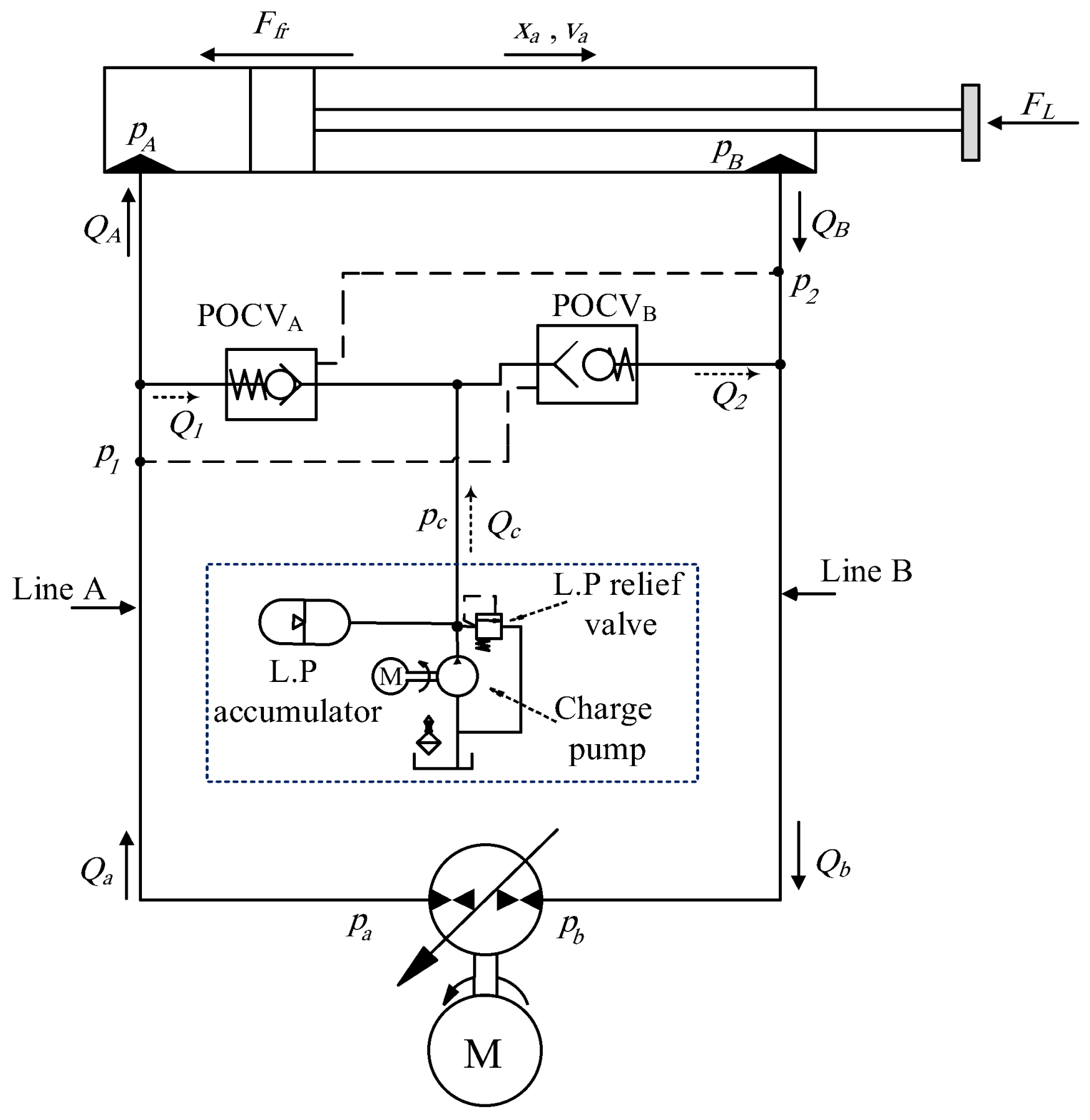
A typical pilot-operated check valves (POCVs) circuit is shown in Figure 1 [17]. In this circuit, both POCVs are opened by pilot signals from cross pressure lines. The pressure differential across the pump is defined as P = p a p b , where p a and p b are the pressures at pump ports a and b, respectively. Neglecting the pump internal leakage, we observe that the pump inflow equals the outflow ( Q ) . When the hydraulic fluid flows from port b to port a, the value of Q is positive, and vice-versa. When P and Q have the same sign, the pump works in pumping mode [6]; otherwise, it works in motoring mode. During transitions from pumping to motoring modes and vice-versa, the circuit operates in switching zones. Regarding the actuator quadrants, when the cylinder velocity, v a , and the external force, F L , have the same sign ( F L is positive when it resists the cylinder during extension, as in Figure 1), the actuator works in resistive mode; otherwise, it works in assistive mode [5]. The equation of motion of the actuator is given by:
m v ˙ a = ( p A A A p B A B ) F f F L
where m represents the equivalent moving mass. Pressures at the actuator ports are denoted by p A and p B , and the piston effective areas are represented by A A and A B . F f denotes the equivalent frictional force.
Clearly, cylinder motion will not begin until the POCVs are in their proper working positions, corresponding to the relevant operational quadrant. For example, with reference to Figure 1, proper motion in the first quadrant of operation is satisfied when POCVB is open and POCVA is closed. Therefore, the circuit operation must be described by the force balance equation, Equation (1), and by equations describing the operation of POCVs. Therefore, we infer that the characteristics of the compensating valves, especially in the switching zones, highly affect the performance. Quadrants of operation and different switching zones in pump-controlled circuits, together with the influence of compensating valves on the circuit performance, are described next.

2.2. Quadrants of Operation

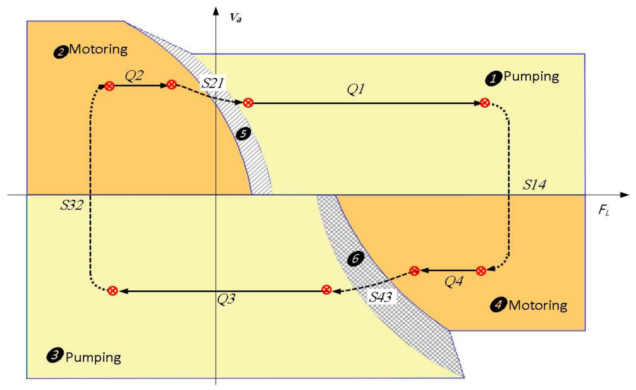
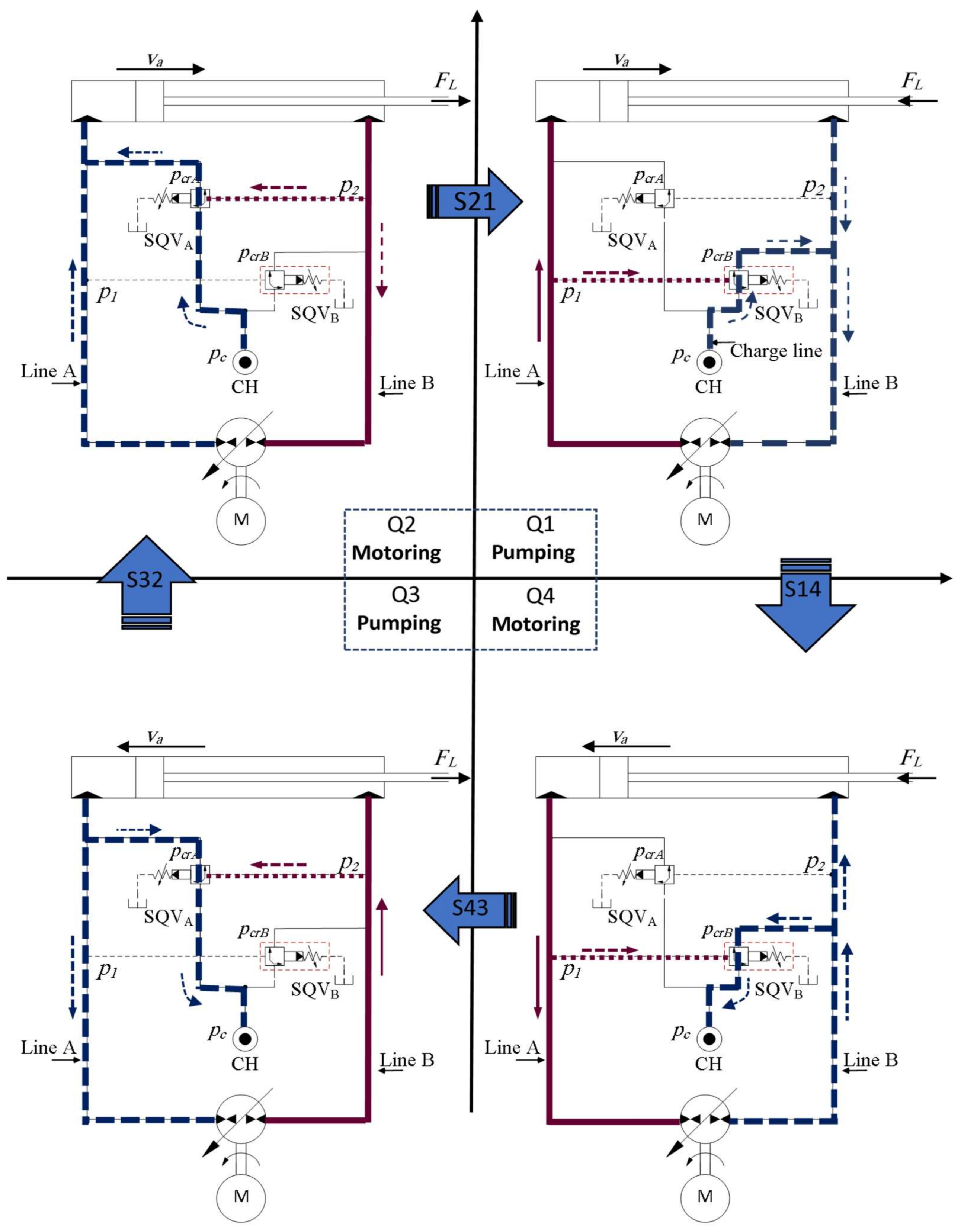
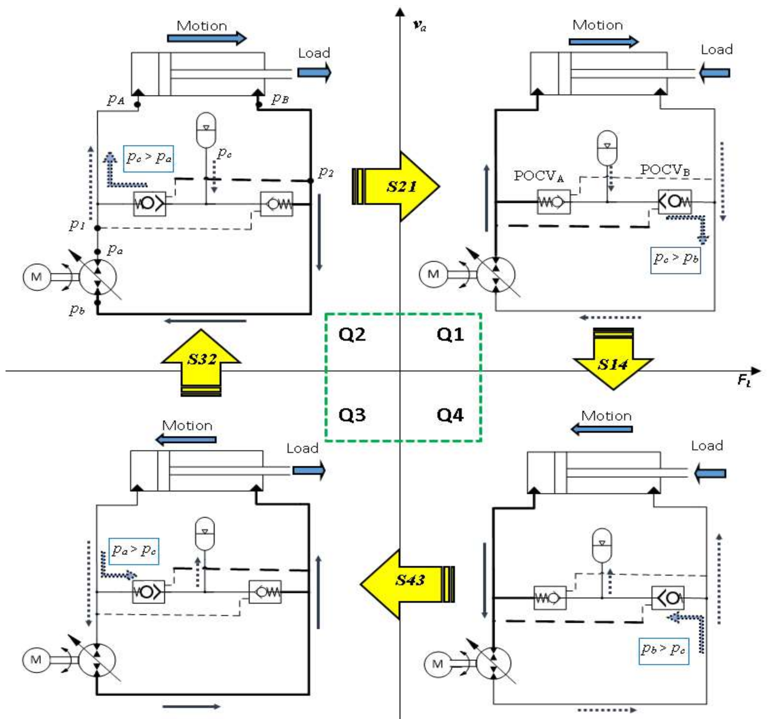
Figure 2 shows flow patterns in each of the four quadrants of operation, Q1, Q2, Q3, and Q4, for the circuit represented in Figure 1. The arrows between quadrants represent the switching zones. The operation sequence depends on the load configuration. The operational sequence represented in Figure 2 is as follows: resistive extension (Q1), assistive retraction (Q4), resistive retraction (Q3), and assistive extension (Q2).
Switching between each two successive quadrants are denoted as S14, S43, S32, and S21. Observe that while the configurations of POCVs do not change at zones S14 and S32, they are switched at zones S43 and S21. The repositioning of the compensating valves causes abrupt variations on the system dynamics. These variations are accompanied by changes in the pump operating mode as well as the actuator velocity. Thus, S43 and S21 can be recognized as regions of potentially poor performance. From Figure 2, we see that zone S21 is situated between quadrants Q2 and Q1, when the cylinder is extending and the pump operation switches from motoring mode to pumping mode. In both quadrants Q1 and Q2, fluid flows from the charge system into the circuit. Therefore, considering the charge pressure, p c , we have that p c > p b in Q1 and p c > p a in Q2. As a result, in zone S21 the pressures at both sides of the circuit are very similar and smaller than the charge pressure, which keeps both POCVs open. Consequently, the charge system supplies both sides of the circuit with hydraulic oil, which reduces the actuator controllability [5]. The other zone of interest is S43, during which cylinder retracts, between quadrants Q4 and Q3. Again, the pump operation switches from motoring mode to pumping mode. In both quadrants, fluid flows from the circuit into the charge system, which means that p a > p c , and p b > p c in quadrants Q4 and Q3, respectively.
Note that the pressures at both sides of the circuit are nearly equal but still higher than p c ; therefore, as the pilot pressures are reduced during the transition zone S43, both POCVs are initially closed [5] and the cylinder ports are, momentarily, blocked. In order to obtain motion at the cylinder, the pump operates in pumping mode, increasing the pressure within line B, which opens POCVA, thus accelerating the cylinder. Conversely, cylinder acceleration increases the pressure in line A, which supports motoring mode and opens POCVB. Once the pump switches to motoring mode, the pressure at line B is reduced, which leads to motion deceleration. Consequently, the pump mode of operation and POCVs configuration keep switching, hence, pressure and velocity oscillate.

2.3. Desired Operational Parameters

Figure 3 shows different quadrants of operation and switching zones for the load–velocity ( F L v a ) diagram (a detailed explanation for this diagram can be found in reference [5]). In this figure, the hatched regions 5 and 6 represent transition zones S21 and S43, respectively. The arrowed cycle in the diagram represents a desired operating cycle with the sequence of operation as configured in Figure 2. The solid and dashed lines in the cycle represent the operation in quadrants and switching zones, respectively. As discussed in the previous section, possible velocity oscillations occur during operation at the switching zones S43 and S21 [5,23]. Thus, one main requirement for this cycle is to obtain damped, smooth, and controllable operation at regions S43 and S21.
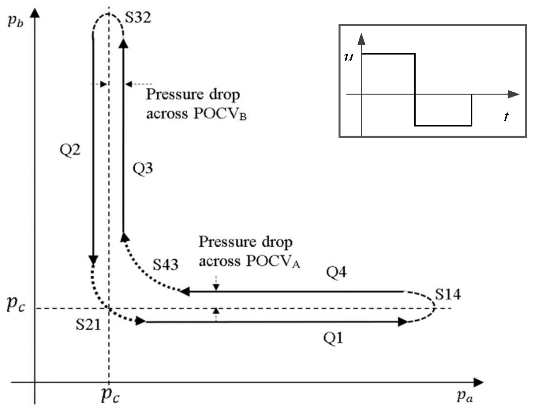
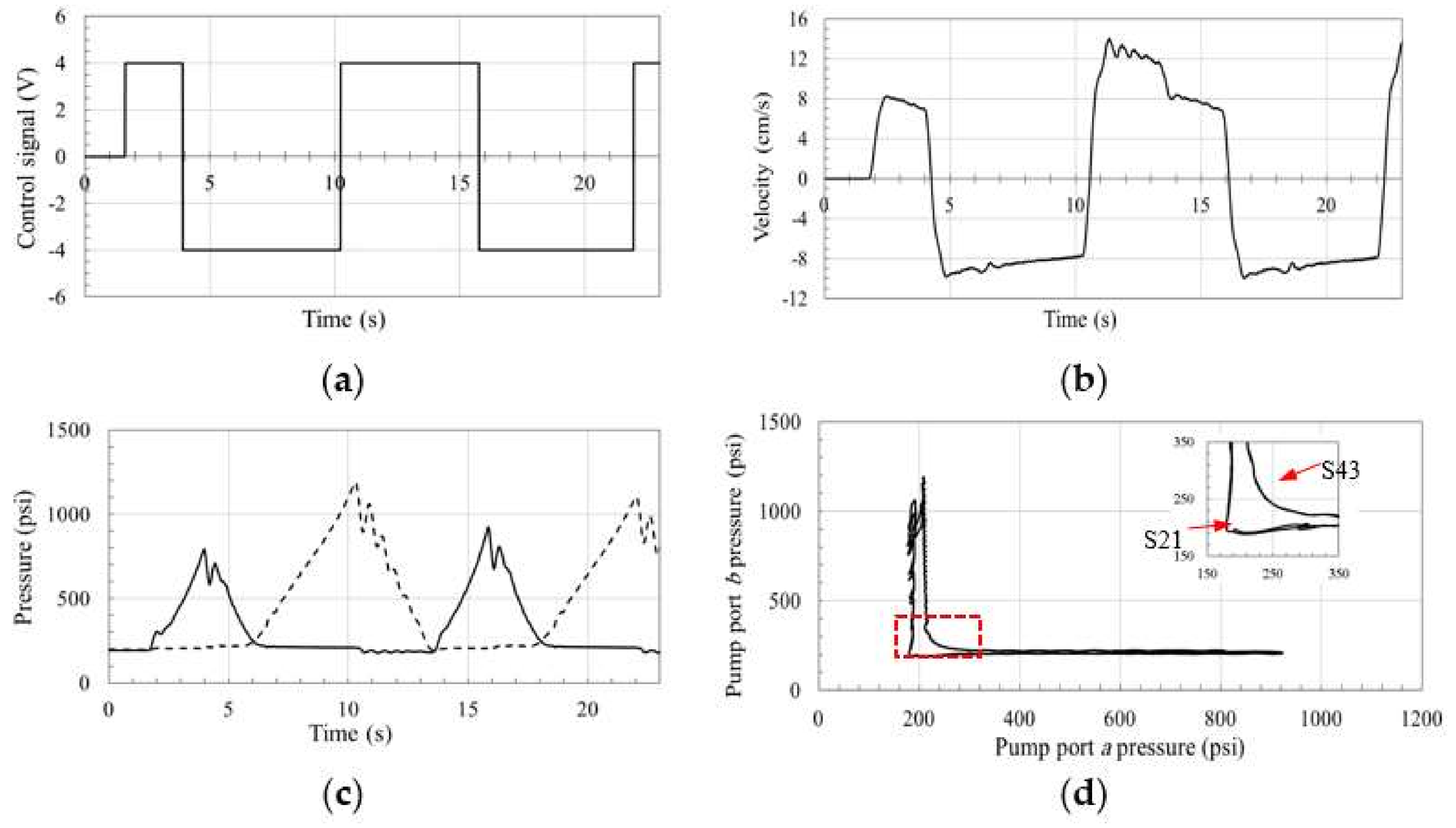
Figure 4 illustrates the desired operating cycle using the pump pressure p a p b plane, for a square control signal. The control signal ( u ) is applied to the pump swash plate to control flow rate and direction. When operating in quadrant Q1, p a is higher than the charge pressure, p c , and it increases as the load increases. On the other hand, p b is lower than p c to allow for flow compensation into line B. The pressure drop ( p c p b ) across the compensating valve depends on its cracking pressure and flow characteristics. The same analogy is applied over the other quadrants of operation for the circuit in Figure 2, and the desired pressure plane of the circuit is plotted in Figure 4. The pressure plane should present a smooth transition between quadrants.

3. Effects of Compensating Valve Types on Performance

In this section, the effects of using different valves to compensate for the differential flows in pump-controlled single-rod hydraulic actuators are discussed using the assessment criterion established in Section 2. Conventionally, compensating valves can be classified as restrictive and non-restrictive. Non-restrictive valves, such as check valves and shuttle valves, provide rapid switching for a fast and uninterrupted motion. However, as reported in [15,23], they deteriorate the system performance during switching phases. Restrictive valves provide extra damping, smooth transition, and reduce the effect of the velocity change on the system dynamics. They, however, reduce the overall system efficiency. Designing and using a limited throttling valve that provides flow restriction only over the critical zones improves performance and minimizes energy losses. Generally, performance is stable when the pump works solely in one mode of operation (either pumping or motoring) at each of the quadrants Q1, Q2, Q3, and Q4 [5,27]. Likewise, performance during switching zones S14 and S32 is expected to be stable, given that the configuration of the compensating valves does not change [5,27]. Reactivation of the compensating valves occurs at the critical switching zones S43 and S21; hence, performance is highly affected by the operational characteristics of these valves. In what follows, the effects of using four types of valves to compensate for the differential flow over the critical zones are discussed.

3.1. Flow Compensation Using Pilot-Operated Check Valves

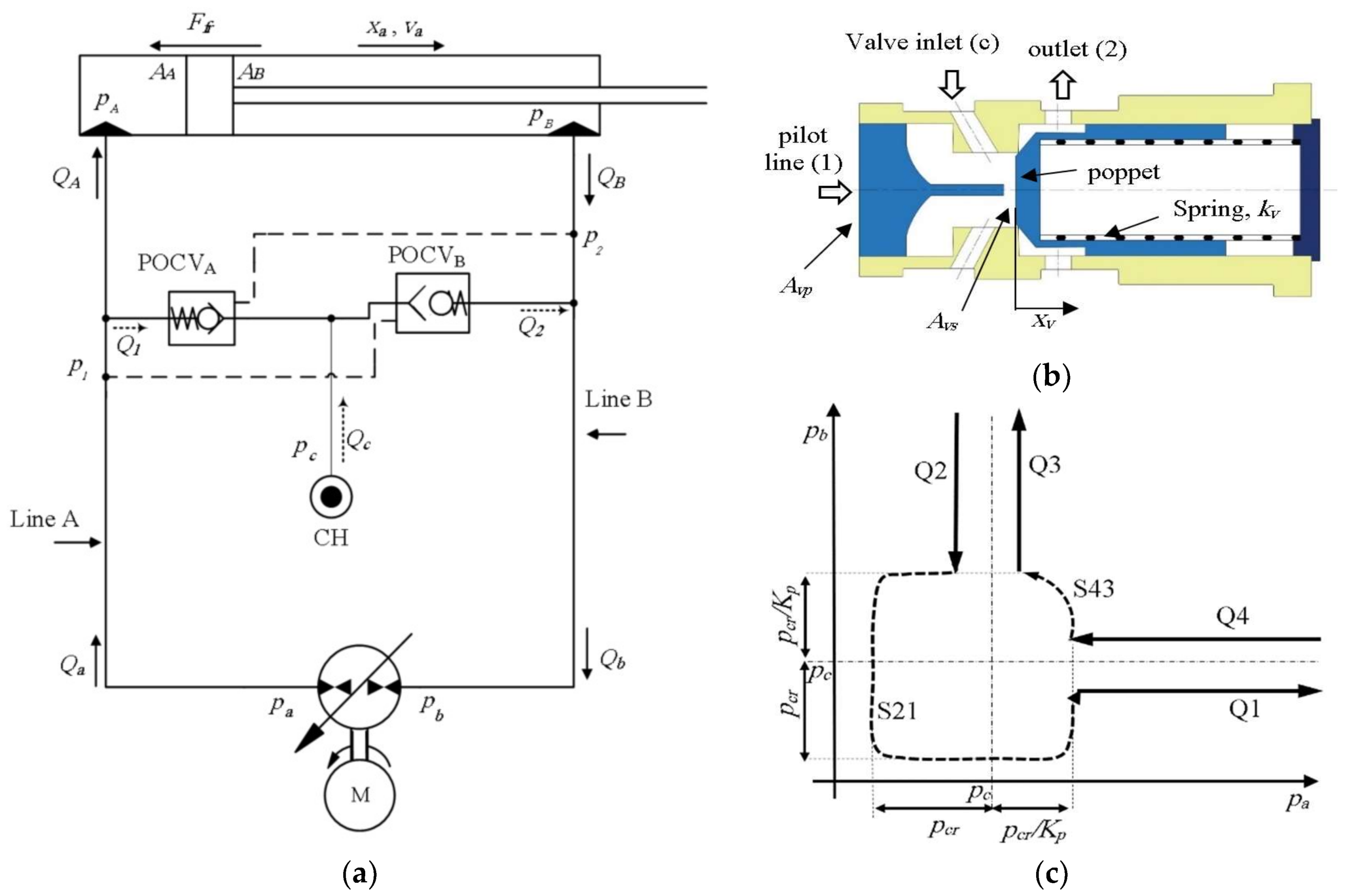
Figure 5a shows a reproduction of circuit shown in Figure 1, where the low-pressure charge system is symbolically represented and denoted as CH. This circuit utilizes POCVs to compensate for the differential flow of single-rod pump-controlled actuators [17]. Figure 5b illustrates the cross-section view of a POCV (notations refer to POCVB, in Figure 5). POCVs are normally closed and are opened in two different ways. The standard way is when the valve opens due to the pressures acting on both sides of the circuit referenced to the charge pressure [28]. Alternatively, the differential pressure across the poppet opens the valve just like a standard check valve. Thus, satisfying any of the following inequalities allows the POCVB to open:
K p ( p 1 p c ) ( p 2 p c ) p c r
p c p 2 p c r
where K p and p c r are the POCV pilot ratio and cracking pressure, respectively. The pilot ratio indicates the pressure amplification within the valve when it operates in piloted mode (typically, K p = 3 ). Based on Equation (3), a threshold cross pressure needed to open the POCVs is approximately given by p c r / K p (see Equation (2)).
Figure 5c shows the expected pressure plane of the circuit with the POCVs. When pressures at both lines of the circuit are close to each other within the threshold margin and higher than charge pressure, both valves are closed [5]. To begin or keep motion, either pressure is expected to become higher than p c + p c r / K p . This condition is fulfilled at zone S43 and is considered a potential cause for actuator velocity oscillations. On the other hand, according to Equation (3), both valves are open when pressures at both sides of the circuit are smaller than or equal to ( p c p c r ), which holds at zone S21. Opening both valves affects the actuator controllability. However, in this case, no oscillatory motion is likely to occur.

3.2. Flow Compensation Using Two-Position Three-Way Shuttle Valve

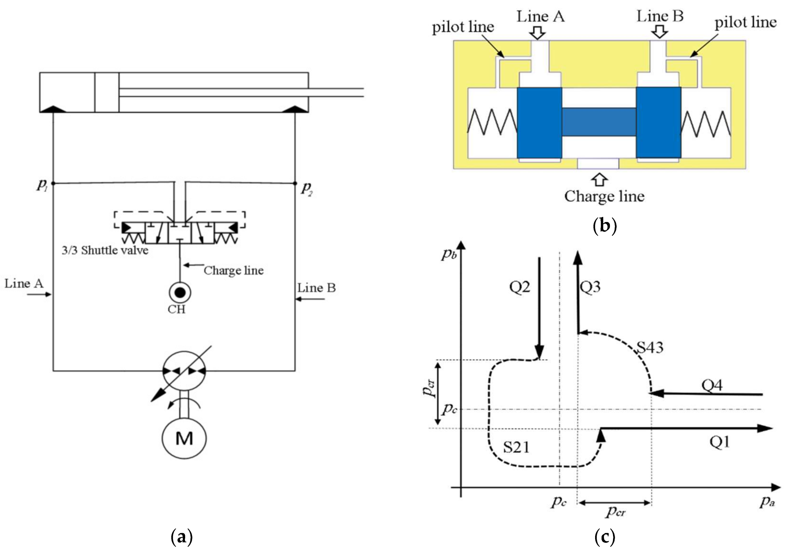
Figure 6a shows the drawing of circuit that utilizes shuttle valve to compensate for the cylinder differential flow. A detailed explanation and operation of the circuit are found in [15,19]. The schematic drawing of a typical 3/3 closed-center shuttle valve (CC-SHV) is illustrated in Figure 6b. Opening of this valve depends on the pressure differential between the two piloting ports and can be described using the following inequality condition:
| p 1 p 2 | p c r
In Equation (4), p c r is the cracking pressure of the valve. Based on the above equation, the CC-SHV blocks both sides of the circuit when the pressure differential between the pilot ports is smaller than p c r . This blockage does not allow flow compensation to/from charge line during S43 and S21 (refer to Figure 2). Accordingly, it causes accumulation of flow and consequently pressure build-up at both sides of the circuits in S43. It also causes lack of flow and consequently pressure drop at both sides of the circuits in S21. Thus, operation is interrupted and potential source of velocity oscillations in both switching zones S43 and S21 is created.
Note that adding anti-cavitation valves to the circuit alleviates oscillations at S21. Anti-cavitation valves are standard check valves that allow flow to the pump inlet from charge system to avoid cavitation. Figure 6c shows the expected performance of the circuit on the pressure plane. Compared to the circuits with POCVs, circuits with the CC-SHVs show a larger switching margins for the same cracking pressure. Note that due to the coupled nature of the valve, CC-SHV switching results in a sudden dynamic change at both sides of the circuit, leading to higher pressure ripples as compared to POCVs. Consequently, they are subjected to larger and more severe potential oscillatory zones in the FL-va plane.

3.3. Flow Compensation Using Three-Position Three-Way Open-Center Shuttle Valve

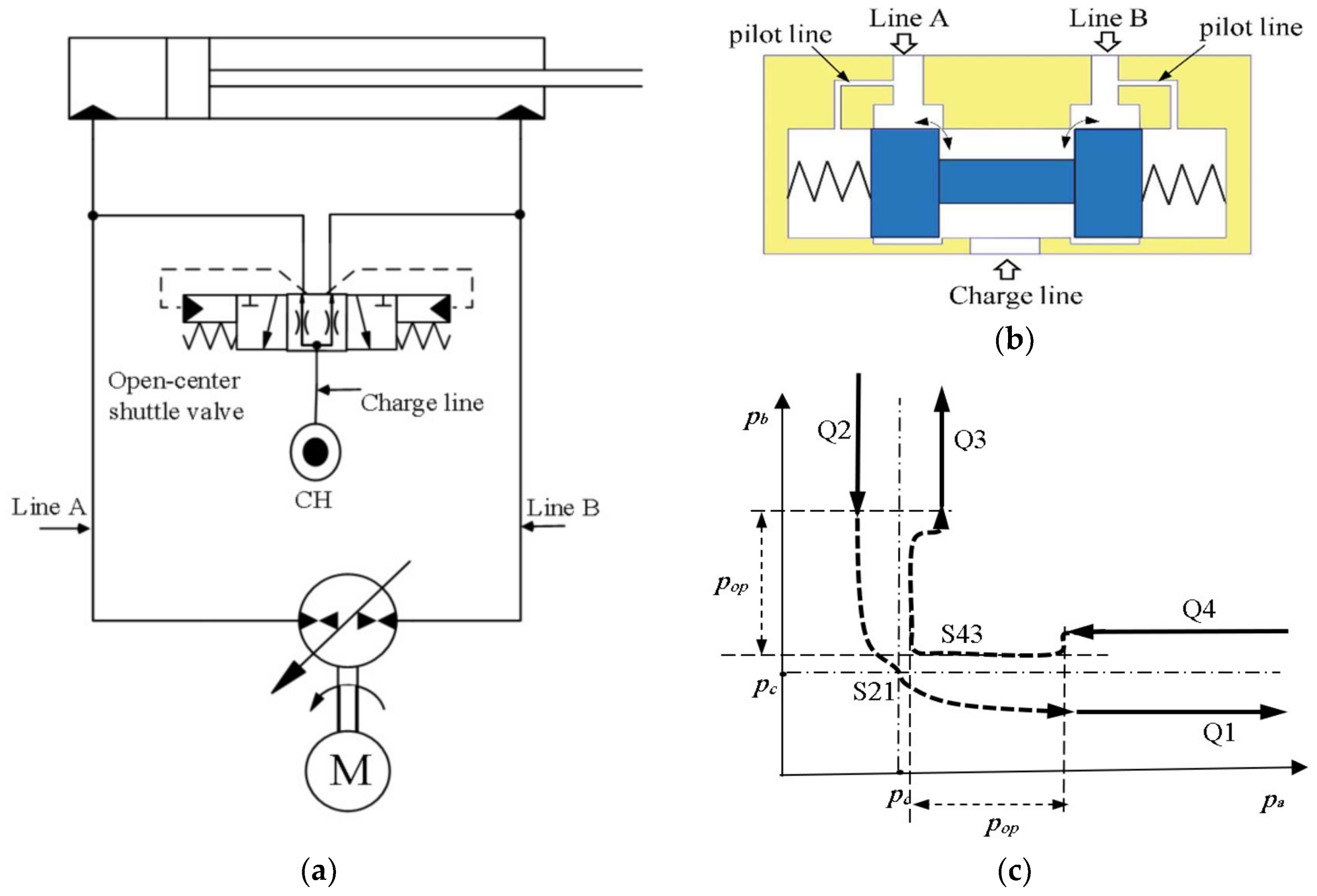
Figure 7a illustrates the schematic and hydraulic symbol of a typical open-center shuttle valve (OC-SHV) [19]. This valve contains an underlapped spool which allows for leakage at neutral position, as shown in Figure 7b. Figure 7c shows the pressure plane performance at critical zones. Mathematical representation of the opening condition is similar to that of the closed-center shuttle valve (CC-SHV) described by Equation (3). This valve makes use of the pre-designed leakage to dampen oscillations within the switching zones.
Leakage occurs only when the pressures at both sides of the circuit are close to each other and valve spool is located within a small displacement margin (about ±0.15 mm) around the center position. At this condition both circuit lines are partially connected to the charge line and their pressures reach charge pressure. When pressure at either of the circuit lines is higher than a specific value (denoted as p o p [19]), only one line of the circuit is connected to charge line.
The effect of using this valve as a solution depends on the pre-designed leakage area within the valve. A smaller leakage area improves performance (i.e., alleviates oscillations) at low speeds while having little effect when the cylinder operates at higher speeds. On the other hand, a higher leakage area alleviates oscillations at high cylinder speeds. However, in this case, system efficiency is compromised and performance at lower speeds deteriorates, in the sense that it becomes less controllable.

4. Flow Compensation Using a Novel Limited Throttling Valve

4.1. Description of the Concept

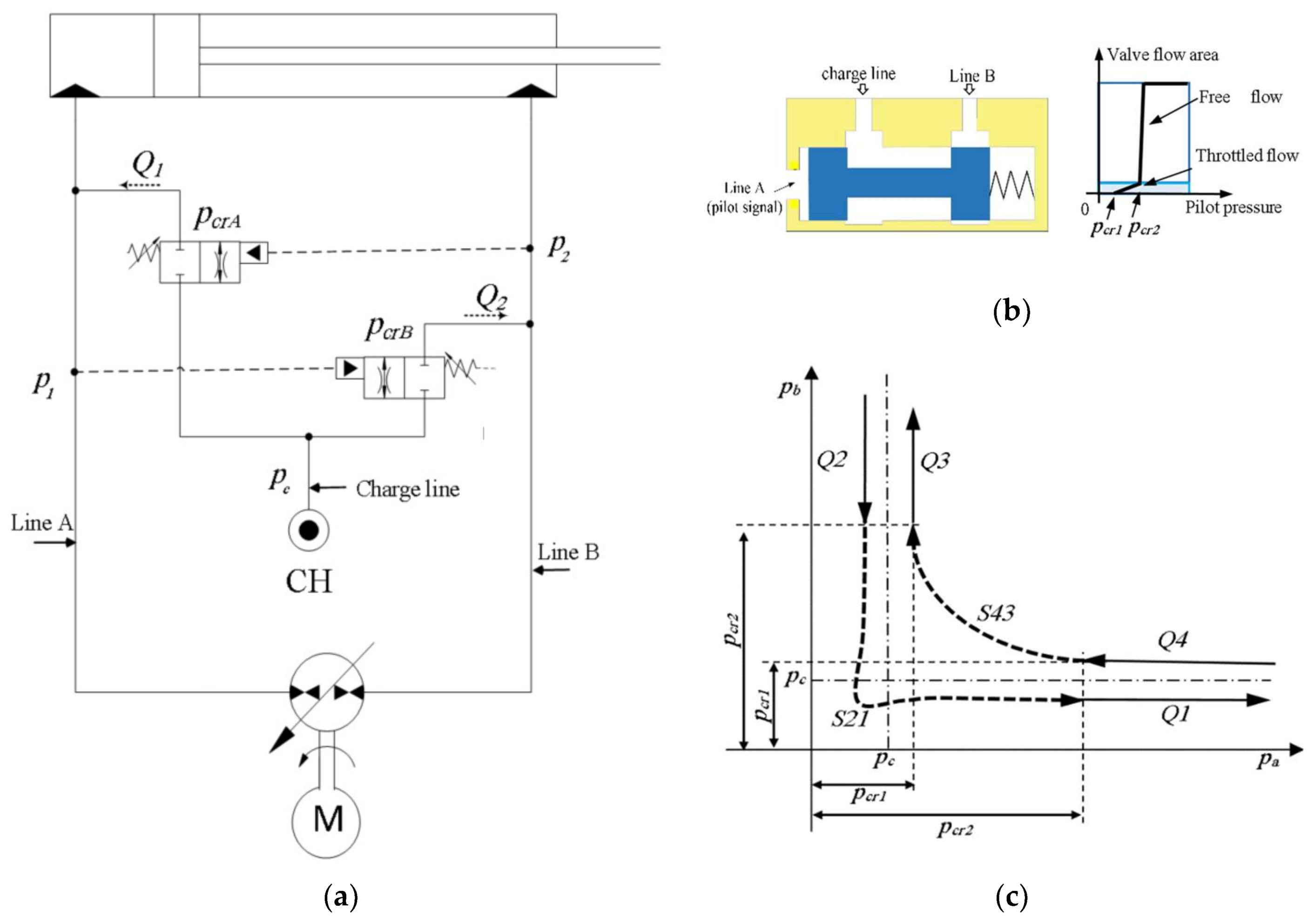
As was described in Section 3, pump-controlled circuits with non-restrictive flow-compensating valves are subjected to velocity oscillations in switching zones. In this section, the use of selective throttling valves that applies throttling over the differential flow only in critical operating regions is proposed. These valves have minimum throttling effect in all other operating regions to preserve efficiency. Schematic drawing of the proposed circuit that incorporates limited throttling valves (LTVs) is shown in Figure 8a. A drawing of the proposed LTV and its flow area versus piloting pressure is illustrated in Figure 8b. LTVs are normally closed pressure-controlled valves. They open when the pilot pressure signal exceeds a critical pressure, p c r 1 , and meters the incoming flow, as long as the pilot pressure remains smaller than a throttling threshold, p c r 2 . The valve is completely open when the pilot pressure becomes greater than p c r 2 . The flow, Q 2 , through a LTV is given by following relation:
Q 2 = { 0 p 1 < p c r 1 C d 1   A 1 2 ρ | p 1 p c |   s i g n   ( p 1 p c ) p c r 1 p 1 < p c r 2 C d 2   A 2 2 ρ | p 1 p c |   s i g n   ( p 1 p c ) p 1 p c r 2
where the leakage flow through the valve is assumed to be zero; C d 1 and A 1 , and C d 2 and A 2 denote the discharge coefficients and flow areas in the restrictive and non-restrictive modes of operation, respectively. Note that C d 2   A 2 must be much larger than C d 1 A 1 . One way to obtain such condition is to design the valve flow area as function of the pilot pressure such that it possesses the relation shown in Figure 8b. This criterion allows throttled switching at the critical zones and throttle-less flow compensation elsewhere. Predetermined cracking pressure, spring stiffness, and area gradient govern the throttling characteristics of the LTVs. Figure 8c illustrates the expected effect of utilizing LTVs in the pressure plane. It shows that transition during S43 is smooth over longer pressure margins, which improves the system’s dynamic response. This is, however, accomplished at the expense of slightly reduced efficiency, whereas a pressure drop in both sides of the circuit is encountered during S21, which is limited by anti-cavitation valves.

4.2. Implementation

From the above discussion, we conclude that the use of standard low-cracking pressure POCVs and SHVs leads to abrupt changes in circuit pressures and, consequently, in the actuator speed. Moreover, at low load conditions where the pressure at both sides of the circuit are close to each other, the actuation of these valves becomes sensitive to small pressure variations. Consequently, the probability for velocity oscillations increases. OC-SHVs overcome the aforementioned problems by providing leakage. However, this solution is valid for specific actuator speeds [5,19]. The use of limited throttling valves that provide throttling during switching modes while allowing free flow elsewhere, dampens oscillations and maintains efficiency.
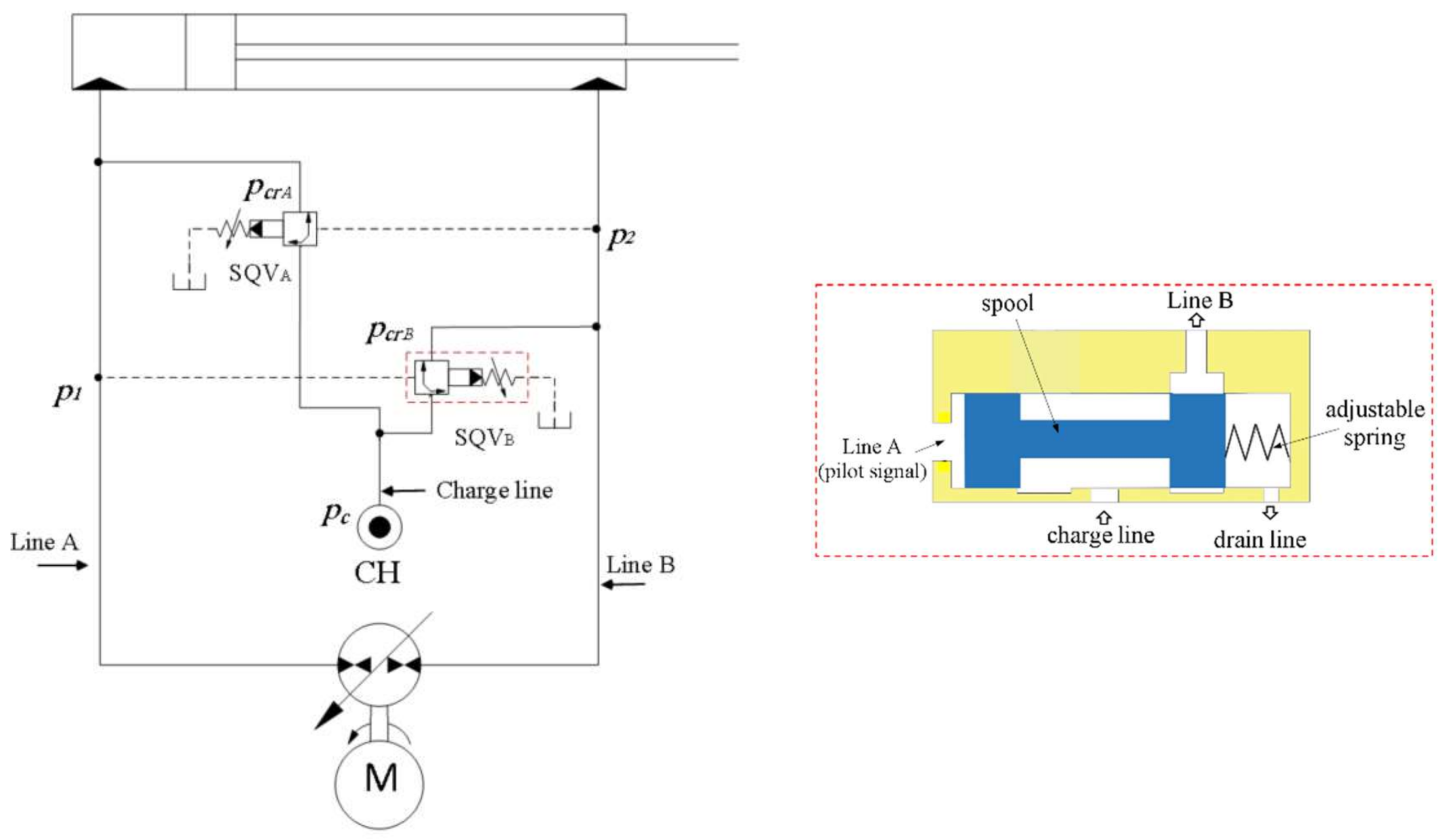
Presently, LTVs are not commercially available. Thus, this circuit has been implemented using two sequence valves (SQVs). Among the different types of SQVs, an externally piloted and bi-directional type have been selected to replace the proposed LTVs. SQVs are normally closed pressure-controlled valves that open when the pilot pressure exceeds a cracking pressure, p c r . They are typically used in conventional valve-controlled circuits to assure proper sequence of operation for operating two or more cylinders. The implemented circuit and the cross-sectional drawing of the SQV are shown in Figure 9. It comprises a variable displacement swash plate pump, connected to a single-rod cylinder. A low-pressure charge system is connected to both sides of the circuit through two SQVs that compensate for the cylinder differential flow. The SQV spool is balanced by an adjustable spring and the pilot pressure from line A. The cracking pressure, p c r , is selected and adjusted based on the charge pressure value. SQVs are selected such that they act like the LTVs; throttle the differential flow when the pilot pressure is smaller than a throttling threshold value and allow for throttle-less flow when the pilot pressure is greater than such value.
As a result, we obtain a damped (smooth) switching at critical zones while keeping a throttle-less flow elsewhere. This circuit is more efficient when compared to the circuit with the POCVs and CBVs (described in [5]), because it only applies throttling over the differential flow. Typically, differential flow represents 25% of the main flow in main circuit lines. Moreover, it uses a smaller number of components, which reduces the complexity and improves the maintainability of the circuit.

5. Experimental Evaluation

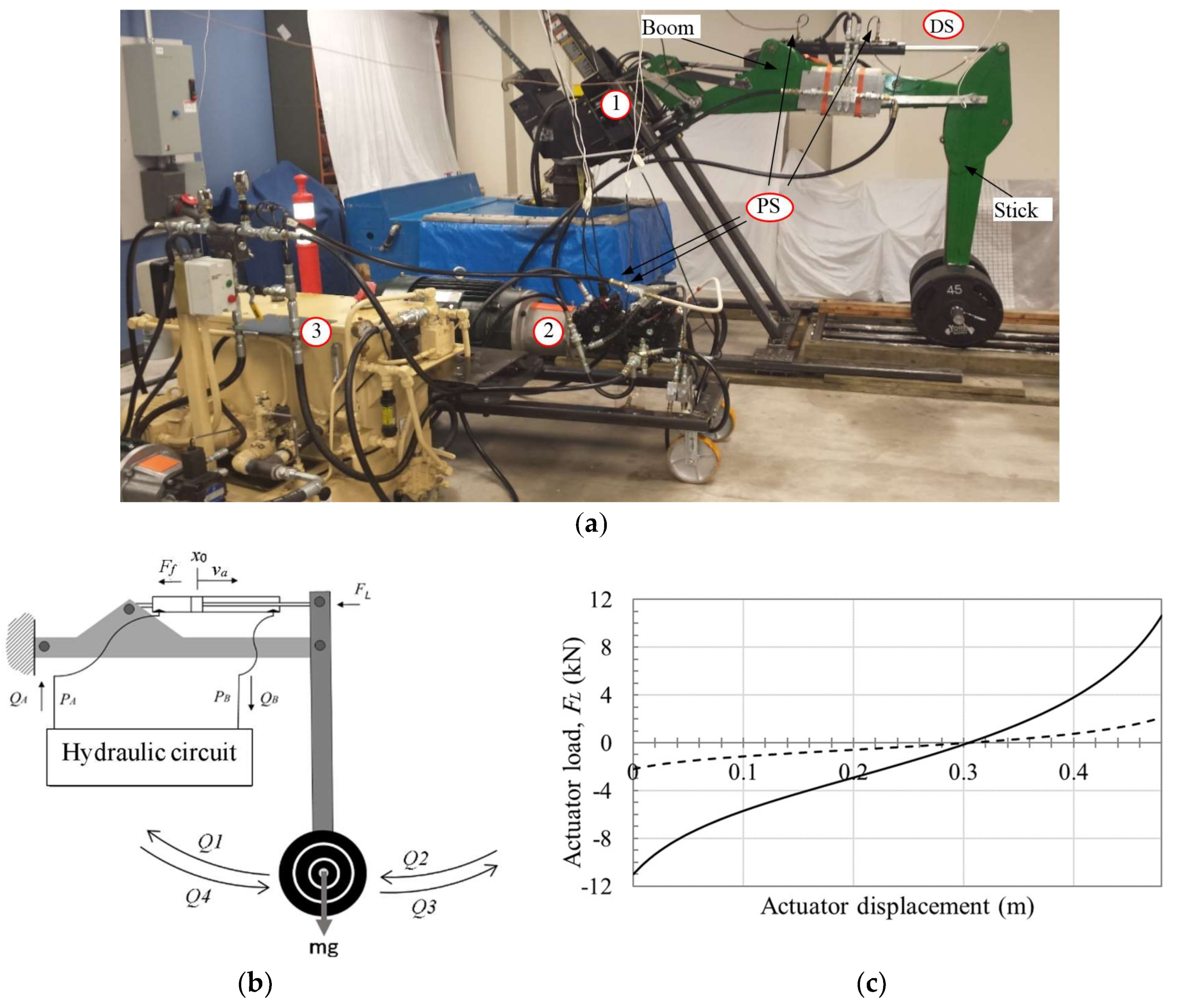
Figure 10a shows the test rig used in the experiment. It consists of a John Deere JD-48 backhoe, a variable swash plate piston pump, a low-pressure charge unit, and instrumentations. The boom of the JD-48 is fixed to the structure while the motion of the stick is controlled by the proposed pump-controlled circuit, as shown in Figure 10b. Different weights can be attached to the implement to simulate realistic loading conditions in the four quadrants of operation. Figure 10c shows the calculated static load at the actuator rod for 41 kg and 368 kg attached masses. Specifications for the different components of the test rig are listed in Table 1.
The proposed circuit along with three different common pump-controlled circuits (described in Section 4) are tested and their performances are evaluated. All circuits have been tested using the test rig described earlier; the only difference between the four tested circuits is the type of flow-compensating valves. The compensating valves that equipped the circuits are: pilot-operated check valves (POCVs), closed-center shuttle valve (CC-SHV), open-center shuttle valve (OC-SHV), and sequence valves (SQVs). The specifications of these valves are listed in Table 2. All circuits have been tested at low and high loading conditions where masses of 41 kg and 368 kg were attached to the implement. Both performance and stability are investigated.
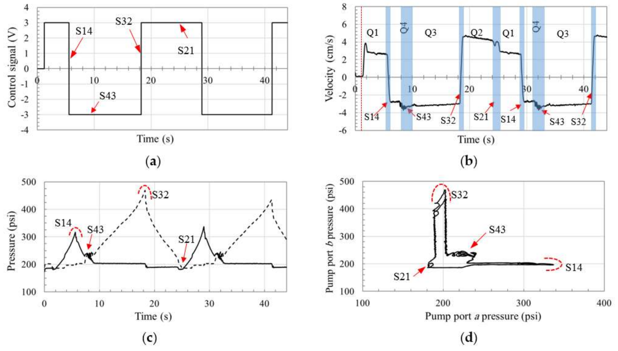
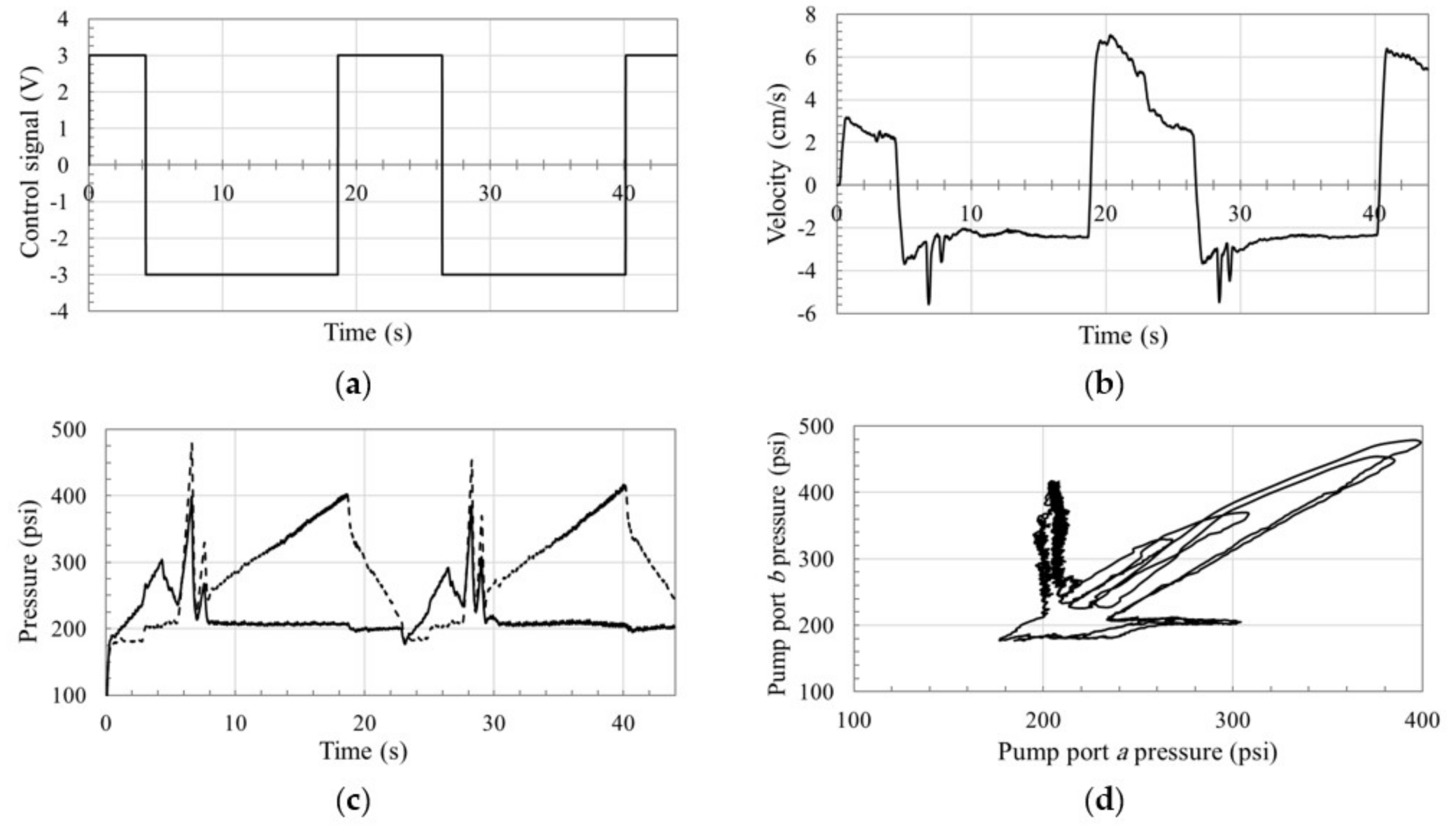
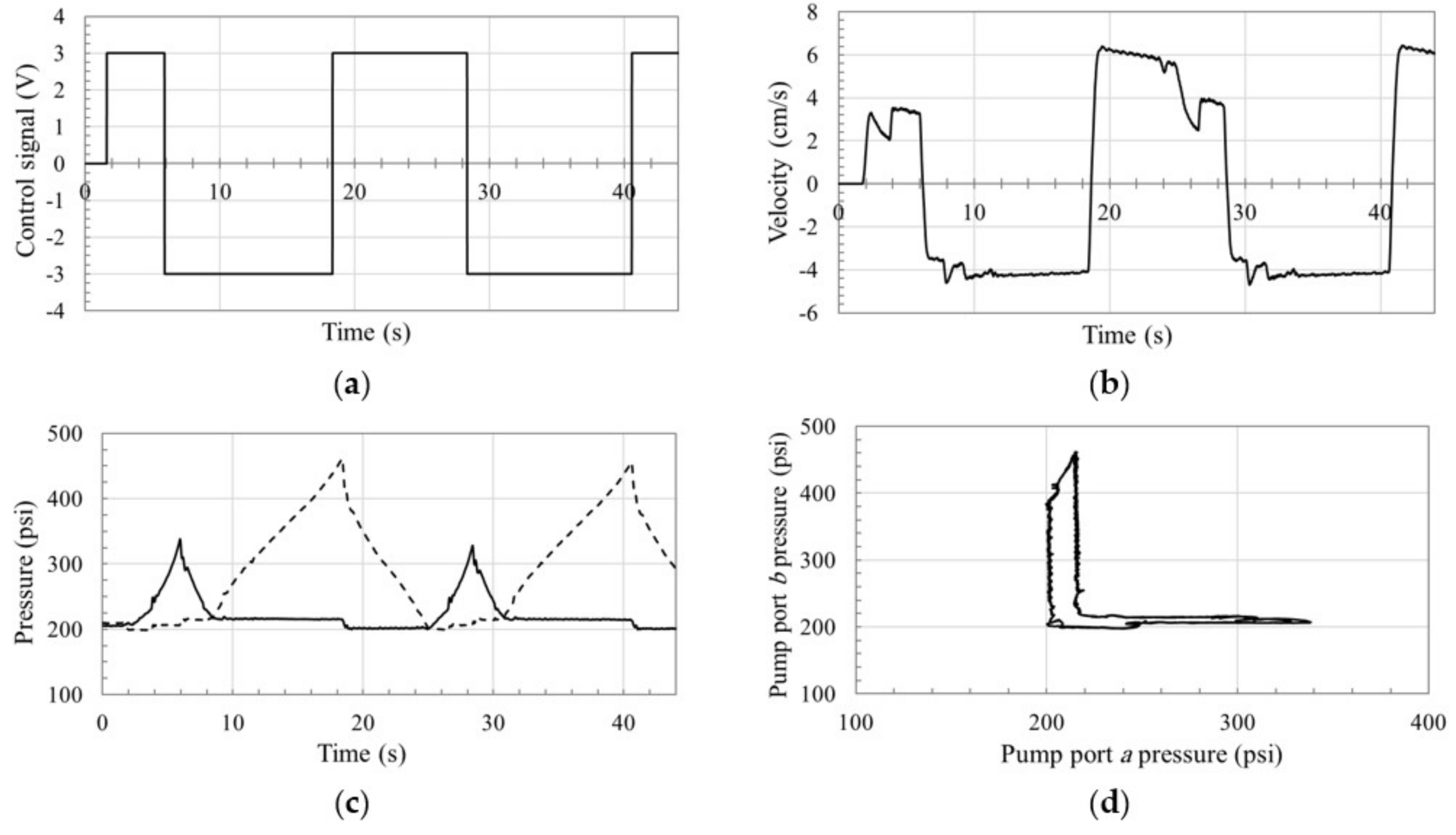
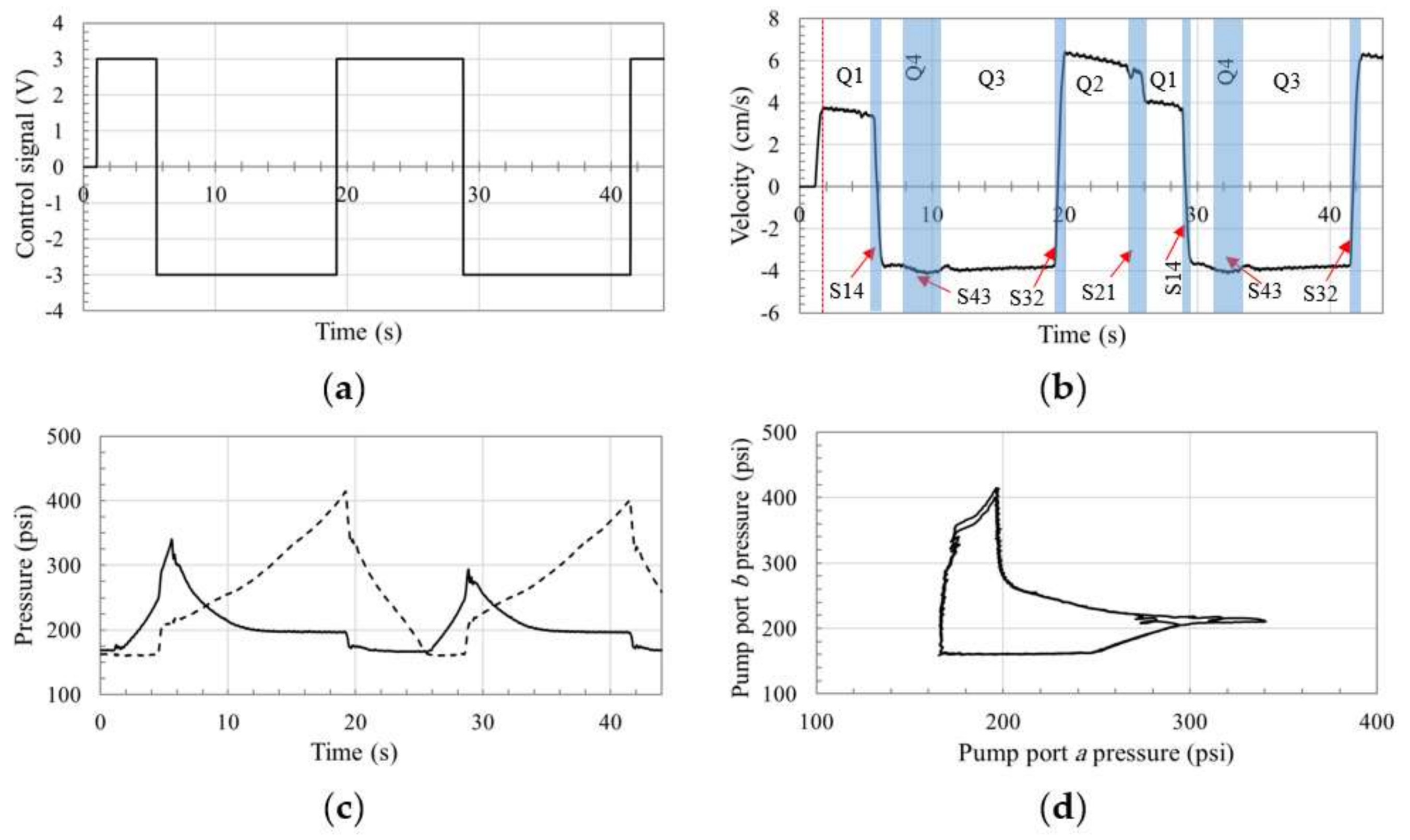
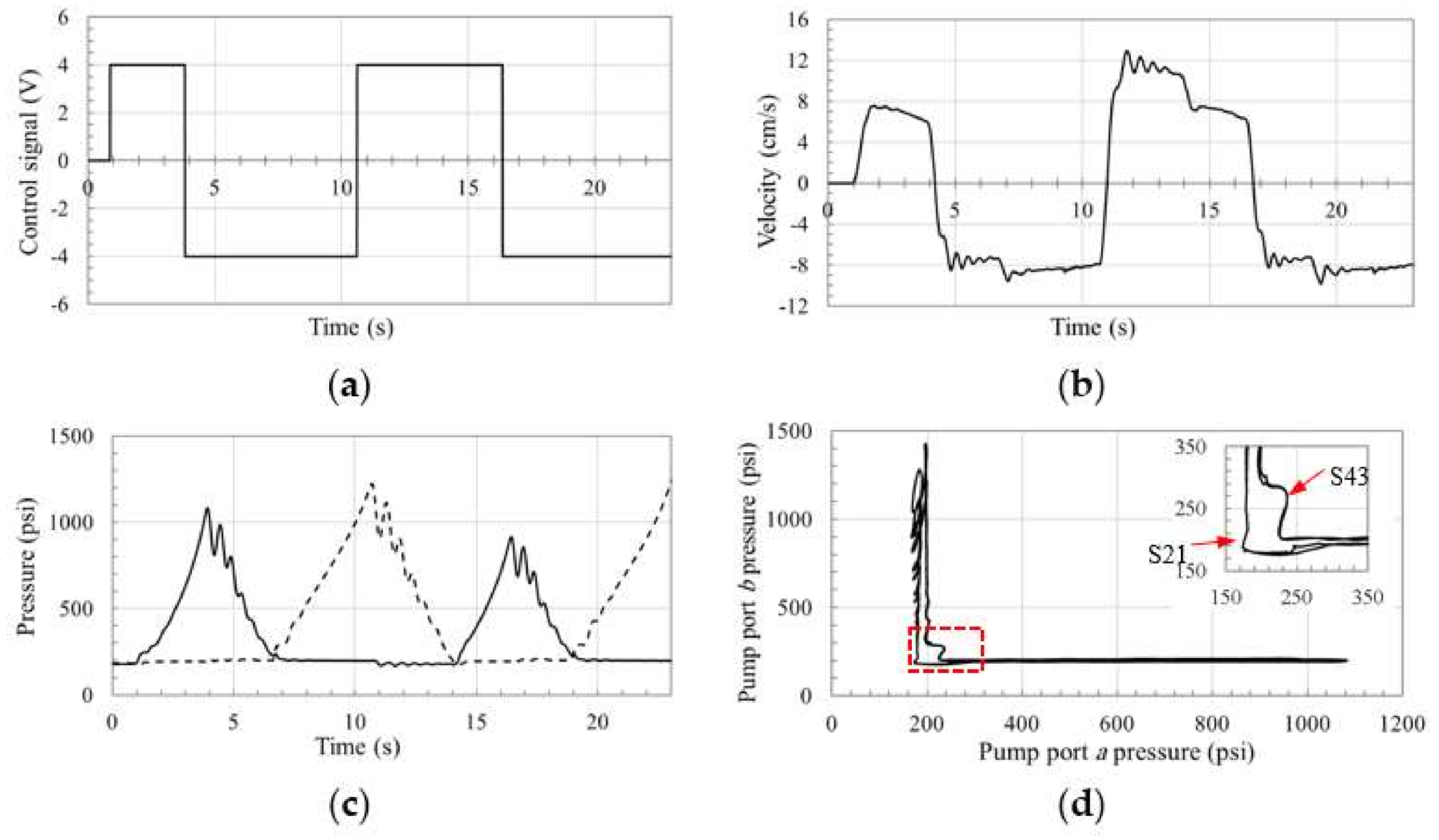
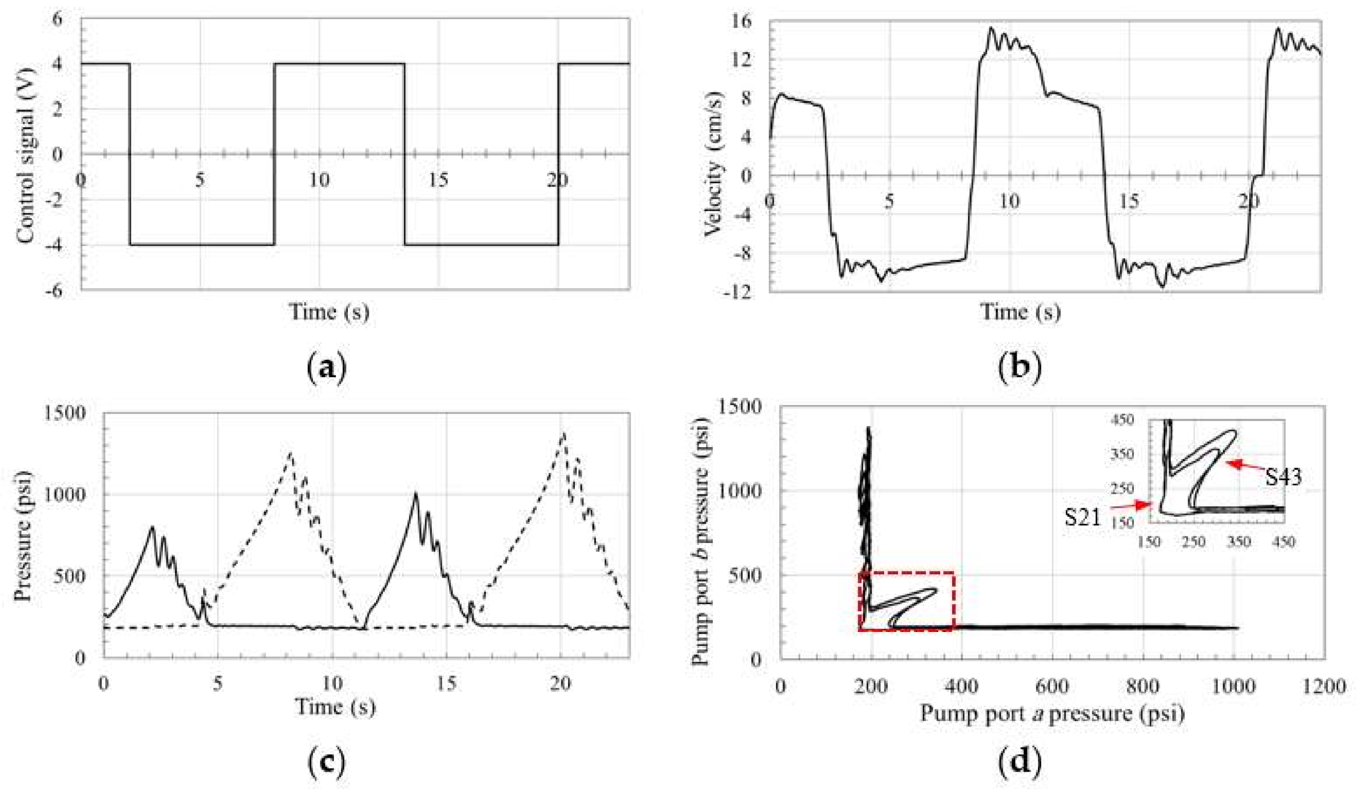
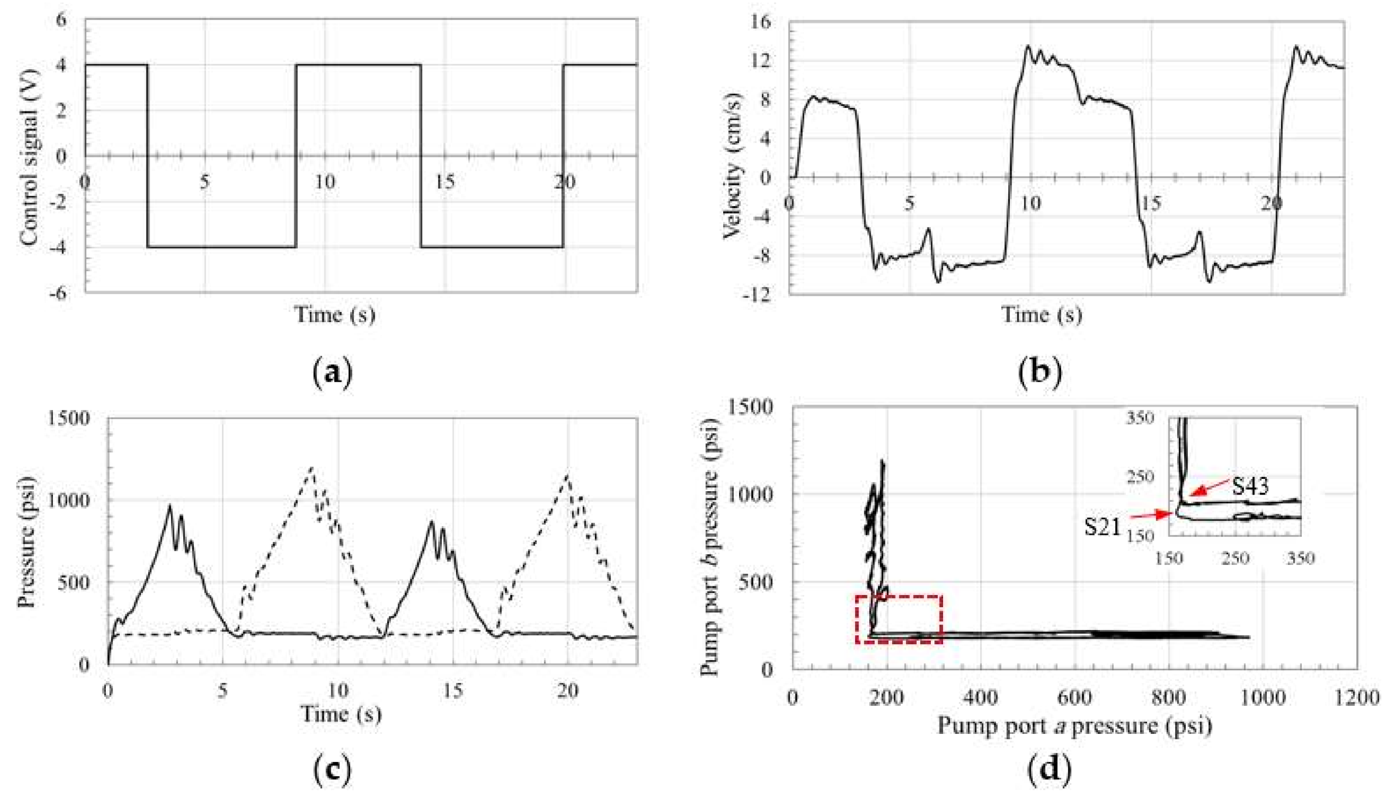
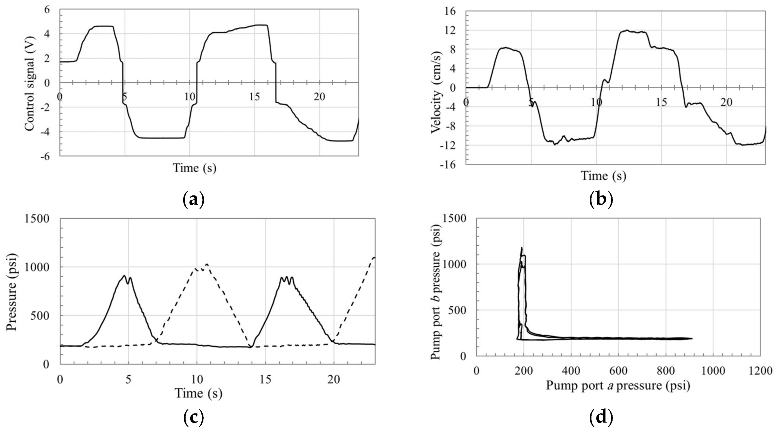
Figure 11, Figure 12, Figure 13 and Figure 14 show the low-load response for circuits that use POCVs, CC-SHV, OC-SHV, and SQVs, respectively. Figure 11a through Figure 14a illustrate the input control signals to the corresponding circuits, which are manually applied for safety reasons. Figure 11b,c through Figure 14b,c show the actuator velocity and pressure responses. Figure 11d through Figure 14 d demonstrate the pressure planes.
The velocity and pressure graphs show that there is no significant performance deterioration during the switching zones S14 and S32 in all circuits, which is expected. This is because switching occurs without re-configuration of the valves. Performance in zone S21 is not oscillatory, while a slight velocity ripple is noticed in responses of all circuits, especially in the circuit using the OC-SHV. In zone S21, a pressure drop is observed in all circuits, especially in circuits using POCVs and CC-SHV. This pressure drop is limited due to the activation of anti-cavitation valves that were originally equipped with the pump. Figure 11 and Figure 12 demonstrate the oscillatory behavior in circuits with POCVs and CC-SHV in the deteriorated performance zone S43. Oscillations in circuit that uses POCVs show lower amplitude and higher frequency when compared to the circuit using the CC-SHV. This can be attributed to the coupled nature of the valve that affects both sides of the circuit simultaneously leading to more severe dynamical changes. On the other hand, Figure 13 and Figure 14 show non-oscillatory transitions for the circuits with OC-SHVs and SQVs in zone S43, which can be attributed to the damping effect of the OC-SHV due to leakage and the SQV due to throttling. However, the circuit using SQVs shows smooth transitions at all switching zones which resembles the ideal valve discussed in Section 2 (see Figure 4). Note that the velocity rise during S43 is less noticeable in this circuit (see Figure 14b), which is attributed to the opening of SQVB to allow throttled flow. Using the proposed limited throttling valve that applies more strict throttling during such switching margin, leads to less effect on the velocity profile. In summary, we can say that the results demonstrate the enhanced performance of the circuit using SQVs at low load conditions. Figure 15 illustrates flow patterns in each of the four quadrants of operation, Q1, Q2, Q3, and Q4, for the proposed circuit, represented in Figure 9. The arrows between quadrants represent the switching zones, S14, S43, S32, and S21.
Figure 16, Figure 17, Figure 18 and Figure 19 illustrate the responses at high-load conditions for circuits using POCVs, CC-SHV, OC-SHV, and SQVs, respectively. Figure 16a through Figure 19a show the manually applied control signals to the corresponding circuits. Slight differences between input signals is attributed to the human factor. Figure 16b,c through Figure 19b,c demonstrate the actuator velocity and pressures at the pump ports for the corresponding circuits as function of time. Figure 16d through Figure 19d show the pressure planes of the aforementioned circuits, and zoomed-out sections for the switching zones S43 and S21 are also displayed. Few oscillations in the velocity and pressure curves are noticed in all the circuits during switching zones S14 and S32, which can be attributed to the nature of the control signal. Smoother control signals do not display these oscillations, as shown in Figure 19. Zone S21shows a non-oscillatory behavior that is similar for all the circuits. This can be attributed to the activation of the two anti-cavitation valves in the circuit. Velocity and pressure graphs demonstrate considerably smaller oscillatory responses for all circuits at switching zone S43. However, responses show small, moderate, and high ripples in circuits with SQVs, POCVs, and SHVs. The ripples in circuits using SHVs can be attributed to the effect of these valves on both sides of the circuit during switching, leading to considerable dynamic changes. Figure 18b shows that the damping effect of the predesigned leakage in the OC-SHV is reduced at higher loads and velocities. Figure 16, Figure 17, Figure 18 and Figure 19 show smoother transitions for the circuit using SQVs when compared to all other circuits at high-load conditions. They also demonstrate the relative improvement in performance for the circuit using POCVs when compared to circuits using SHVs.
To further emulate realistic operation, the proposed circuit in Figure 9 was controlled through a joystick input signal. One representative experiment for the circuit operation is shown in Figure 19. Note that, servo-controller mechanism of the pump used in the test rig possesses a dead zone of ±1.8 V, as denoted in the pump operation manual. Therefore, the pump controller does not respond to the joystick control signals within this range. Figure 19b shows the actuator velocity response, where good matching to the control signal and smooth switching are observed. Minor ripples are noticed at 5, 10, 17, and 23 s, which can be attributed to the dead zone effect. Figure 19c,d illustrate the pressures at both sides of the pump versus time and the pressure plane of the circuit where a smooth response can be observed. We also notice the absence of pressure oscillations in zones S14 and S32 that were experienced in Figure 16 through Figure 19, due to the relative smoothness of the control signal.

6. Energy Consumption Study

Power consumptions of the proposed circuit, in Figure 9, and three other circuits are calculated from experimental data. Based on the pattern of motion in Figure 16, Figure 17, Figure 18 and Figure 19, the net hydraulic power delivered to the circuit, W ph , is calculated. W ph = ( p a p b ) Q p , where ( p a p b ) is the pressure difference across the pump ports and Q p comes from the multiplication of the actuator velocity by the piston effective area. The average values of the net delivered hydraulic power to the different systems are 62.8, 64.5, 63.2, and 62.6 V for the circuits with the POCVs, CC-SHV, OC-SHV, and SQVs, respectively. These results show that power consumptions of all circuits are close to each other. The differences can be attributed to the slight difference in experiments patterns of motion.
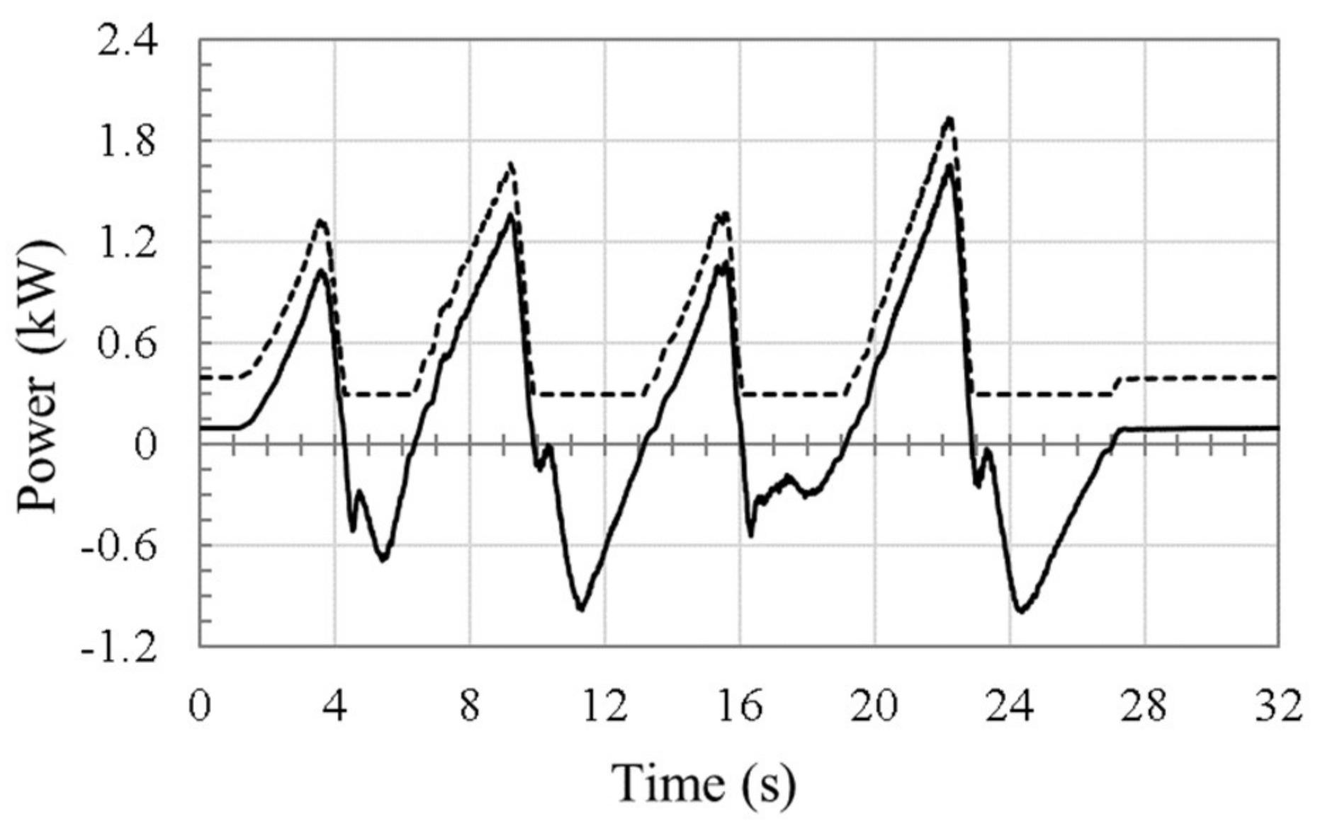
One more energy study is performed to prove efficiency superiority of proposed pump-controlled circuit compared to one of the latest-technology valve-controlled circuits. Based on the motion pattern in Figure 20, power consumption of the proposed circuit is calculated and compared to that of a similar valve-controlled load sensing (LS) circuit 4, as shown in Figure 21.
In this experiment, the net hydraulic power at the circuit is obtained adding the main pump and charge pump powers. The main pump power is calculated from experimental data using the aforementioned formula. The charge pump power, W cph = η c   p c   Q c , where p c , Q c , and η c are the charge pump pressure, flow rate, and efficiency, respectively. The average delivered hydraulic power from pumps to circuit in the proposed circuit is 258.2 W. On the other hand, the average received (regenerated) hydraulic power from circuit to pumps is 127.8 W. Thus, the total consumed hydraulic power by proposed circuit is 130.4 W, while in the LS circuit the delivered power is 558.2 W. The delivered hydraulic power from a LS pump to the circuit has been calculated with the formula: W ph = [ ( p a p b ) + Δ p L S ] Q where, Δ p L S is the difference between the supplied pressure and the pressure required by the highest load in the circuit, which typically ranges from 300 psi to 450 psi [29]. Conservatively, this value has been chosen to be as low as 300 psi. Besides, the studied actuator is typically the one that carries the highest load in a multi-actuator excavator.
Based on these assumptions, the hydraulic power delivered by the pump to the hydraulic circuit in the proposed circuit is approximately 23% of that delivered by the LS pump. Note that the indicated power here is not the total power consumed by the circuit, but the hydraulic power delivered to or received by the pumps. To calculate the total consumed electric power in this experiment, efficiencies of both pump and electric motor should be considered.
7. Conclusions

In this paper, the effects of a number of flow-compensating valves on the performance of a pump-controlled hydraulic circuit for single-rod actuators have been analyzed and compared for the first time. Pressure planes for the circuits with pilot-operated check valves, closed-center shuttle valve, open-center shuttle valve, and the newly proposed limited throttling valves were used for performance evaluation. It was experimentally shown that circuits with shuttle valves encounter more challenges in all switching zones, due to the valve switching dynamics at both sides of the circuit. Performance improvements in circuits with open-center shuttle valves deteriorated at higher loads and velocities. On the other hand, circuits with pilot-operated check valves experienced performance issues at low-load conditions, while showing an improved performance as the load increased. The proposed limited throttling valve concept enhanced performance during all loading conditions including realistic joystick-operated velocity control. Furthermore, energy studies showed that power consumptions of all circuits are close to each other. The proposed circuit showed superior efficiency when compared to a similar load-sensing circuit. The calculated hydraulic power delivered by the pump to the actuator in the proposed limited throttling valve circuit was about 23% of the power delivered by a LS pump.

Acknowledgments

The authors would like to thank the Natural Sciences and Engineering Research Council (NSERC) of Canada for providing financial support for this research.

Author Contributions

A.I. designed the hydraulic circuit and the test rig, provided theoretical analysis, conducted data gathering, data analysis and wrote the paper. M.R. contributed to the construction of the test rig, running experiments and gathering of data. E.J. contributed to the design and construction of the test rig. N.S. initiated, coordinated and supervised the research work that resulted in publication of this paper, contributed to the analysis of data and writing the paper.

Conflicts of Interest

The authors declare no conflict of interest. The founding sponsors had no role in the design of the study; in the collection, analyses, or interpretation of data; in the writing of the manuscript, and in the decision to publish the results.

References

  1. Ivantysynova, M. Innovations in Pump Design—What Are Future Directions? In Proceedings of the 7th JFPS International Symposium on Fluid Power, Toyama, Japan, 15–18 September 2008; pp. 64–95. [Google Scholar]
  2. Michel, S.; Weber, J. Energy-efficient electrohydraulic compact drives for low power applications. In Proceedings of the Fluid Power and Motion Control (FPMC 2012), Bath, UK, 12–14 September 2012. [Google Scholar]
  3. Ritelli, G.F.; Vacca, A. Energetic and dynamic impact of counterbalance valves in fluid power machines. Energy Convers. Manag. 2013, 76, 701–711. [Google Scholar] [CrossRef]
  4. Zemmerman, J.D.; Pelosi, M.; Williamson, C.A.; Ivantysynova, M. Energy Consumption of an LS Excavator Hydraulic System. In Proceedings of the ASME International Mechanical Engineering Congress and Exposition (IMECE), Seattle, WA, USA, 11–15 November 2007; pp. 117–126. [Google Scholar]
  5. Imam, A.; Rafiq, M.; Jalayeri, E.; Sepehri, N. Design, implementation and evaluation of a pump-controlled circuit for single rod actuators. Actuators 2017, 6, 10. [Google Scholar] [CrossRef]
  6. Costa, G.; Sepehri, N. Hydrostatic Transmissions and Actuators: Operation, Modelling and Applications; Wiley: London, UK, 2015. [Google Scholar]
  7. Cleasby, K.G.; Plummer, A.R. A novel high efficiency electrohydrostatic flight simulator motion sysytem. In Proceedings of the Fluid Power and Motion Control (FPMC 2008), Bath, UK, 10–12 september 2008. [Google Scholar]
  8. Rydberg, K.-E. Hydraulic Servo Systems, Course # TMHP51; Linköping University: Linköping, Sweden, 2008. [Google Scholar]
  9. Gardellin, D. Duty Cycle—Electric vs. Pneumatic Actuators. 2012. Available online: www.onyxvalve.com/uploads/docs/Duty_Cycle.pdf (accessed on 1 March 2017).
  10. Bossche, D. The A380 flight control electrohydrostatic actuators, achievements and lessons learnt. In Proceedings of the 25th International Congress of Aeronautical Sciences, Hamburg, Germany, 3–8 September 2006. [Google Scholar]
  11. Li, J.; Fu, Y.; Wang, Z.; Zhang, G. Research on fast response and high accuracy control of an airborne electro hydrostatic actuation system. In Proceedings of the 2004 International Conference on Intelligence, Mechatronics and Automotion, Chengdu, China, 26–31 August 2004. [Google Scholar]
  12. Biedermann, O.; Bildstein, M. Development, Qualification and Verification of the A380 Spoiler EBHA. In Proceedings of the Recent Advances in Aerospace Actuation Systems and Components, Toulouse, France, 24–26 November 2004. [Google Scholar]
  13. Quan, Z.; Quan, L.; Zhang, J. Review of energy efficient direct pump controlled cylinder electro-hydraulictechnology. Renew. Sustain. Energy Rev. 2014, 35, 336–346. [Google Scholar] [CrossRef]
  14. Jalayeri, E.; Imam, A.; Sepehri, N. A Throttle-less Single Rod Hydraulic Cylinder Positioning System for Switching Loads. Case Stud. Mechan. Syst. Signal Process. 2015, 1, 27–31. [Google Scholar] [CrossRef]
  15. Wang, L.; Book, W.J.; Huggins, J.D. A hydraulic circuit for single rod cylinder. J. Dyn. Syst. Meas. Control 2012, 134, 011019. [Google Scholar] [CrossRef]
  16. Jalayeri, E.; Imam, A.; Tomas, Z.; Sepehri, N. A throttle-less single-rod hydraulic cylinder positioning system: Design and experimental evaluation. Adv. Mech. Eng. 2015, 7, 1–14. [Google Scholar] [CrossRef]
  17. Rahmfeld, R.; Ivantysynova, M. Displacement controlled linear actuator with differential cylinder—A way to save primary energy in mobile machines. In Proceedings of the 5th International Conference on Fluid Power Transmission and Control (ICFP’2001), Hangzhou, China, 3–5 April 2001. [Google Scholar]
  18. Heybroek, K.; Palmberg, J.; Larsson, J. Open circuit solution for pump controlled actuators. In Proceedings of the 4th FPNI-PhD Symposium, Sarasota, FL, USA, 13–17 June 2006. [Google Scholar]
  19. Caliskan, H.; Balkan, T.; Platin, B.E. A Complete Analysis and a Novel Solution for Instability in Pump Controlled Asymmetric Actuators. J. Dyn. Syst. Meas. Control 2015, 137, 091008. [Google Scholar] [CrossRef]
  20. Hewett, A. Hydraulic Circuit Flow Control. US Patent 5,329,767 A, 19 July 1994. [Google Scholar]
  21. Hippalgaonkar, R.; Ivantysynova, M. A Series-Parallel Hydraulic Hybrid Mini-Excavator with Displacement Controlled Actuators. In Proceedings of the 13th Scandinavian International Conference on Fluid Power (SICFP2013), Linköping, Sweden, 3–5 June 2013. [Google Scholar]
  22. Grabbel, J.; Ivantysynova, M. Model adaptation for robust control design of hydraulic joint servo actuators. In Proceedings of the 4th International Symposium on Fluid Power Transmission and Control (ICFP 2003), Wuhan, China, 8–10 April 2003; pp. 16–24. [Google Scholar]
  23. Williamson, C.; Monika, I. Pump Mode Prediction for Fourquadrant Velocity Control of Valveless Hydraulic Actuators. In Proceedings of the 7th JFPS International Symposium on Fluid Power, Toyama, Japan, 15–18 September 2008; pp. 323–328. [Google Scholar]
  24. Altare, G.; Vacca, A. A Design solution for efficient and compact electro-hydraulic Actuators. In Proceedings of the Dynamics and Vibroacoustics of Machines (DVM2014), Samara, Russia, 15–17 September 2014. [Google Scholar]
  25. Pugi, L.; Pagliai, M.; Nocentini, A.; Lutzemberger, G.; Pretto, A. Design of a hydraulic servo-actuation fed by a regenerative braking system. Appl. Energy 2017, 187, 96–115. [Google Scholar] [CrossRef]
  26. Ivantysynova, M. The swash plate machine for displacement control unit with great development potentiality. In Proceedings of the First International Fluid Technology Colloqium (IFK), Aachen, Germany, 17–18 March 1998. [Google Scholar]
  27. Williamson, C.A. Power Management for Multi-Actuator Mobile Machines with Displacement Controlled Hydraulic Actuators; Purdue University: West Lafayette, IN, USA, 2010. [Google Scholar]
  28. Zimmerman, J.D. Toward Optimal Multi-Actuator Displacement Controlled Mobile Hydraulic Systems; Purdue University: West Lafayette, IN, USA, 2012. [Google Scholar]
  29. Scherer, M.; Geimer, M.; Weiss, B. Contribution on Control Strategies of Flow-On-Demand Hydraulic Circuits. In Proceedings of the 13th Scandinavian International Conference on Fluid Power (SICFP2013), Linköping, Sweden, 3–5 June 2013. [Google Scholar]
Figure 1. Circuit utilizing pilot-operated check valves in first quadrant of operation.
Actuators 07 00013 g001
Figure 2. Flow patterns in four quadrants of operation and switching zones of the circuit shown in Figure 1, in the F L v a plane.
Actuators 07 00013 g002
Figure 3. Desired operation of pump-controlled circuit in F L v a plane.
Actuators 07 00013 g003
Figure 4. Pressure plane of pump given the square input signal shown in the inset.
Actuators 07 00013 g004
Figure 5. Circuit with pilot-operated check valves to compensate for cylinder differential flow: (a) schematic drawing of circuit; (b) drawing of pilot-operated check valve (POCV); (c) expected pressure plane performance at critical zones.
Actuators 07 00013 g005
Figure 6. Circuit equipped with shuttle valve to compensate for cylinder differential flow: (a) schematic drawing of the circuit; (b) drawing of closed-center shuttle valve (CC-SHV); (c) expected pressure plane performance at critical zones.
Actuators 07 00013 g006
Figure 7. Circuit with open-center shuttle valve to compensate for cylinder differential flow: (a) schematic drawing of the circuit; (b) drawing of open-center shuttle valve (OC-SHV); (c) expected pressure plane performance at critical zones.
Actuators 07 00013 g007
Figure 8. Circuit with limited throttling valves to compensate for cylinder differential flow: (a) schematic drawing of the circuit; (b) drawing of proposed valve and throttling area as function of pilot pressure; (c) expected pressure plane performance at critical zones.
Actuators 07 00013 g008
Figure 9. Circuit with limited throttling valves that uses two sequence valves; inset shows cross-section drawing of SQVB. SQV, sequence valve.
Actuators 07 00013 g009
Figure 10. Test rig; (a) photo showing the main components: (1) JD-48 backhoe structure, (2) main pump unit, (3) charge pump unit, (PS) pressure sensors, and (DS) displacement sensor; (b) setup scheme; (c) calculated static load at actuator rod, FL, for 368 kg (solid line) and 41 kg (dashed line) attached masses.
Actuators 07 00013 g010
Figure 11. Performance of circuit using POCVs for a 41 kg attached mass: (a) control signal; (b) actuator velocity; (c) pressures at the pump ports a (solid line) and b (dotted line); (d) pump pressure plane.
Actuators 07 00013 g011
Figure 12. Performance of circuit using CC-SHV for a 41 kg attached mass: (a) control signal; (b) actuator velocity; (c) pressures at the pump ports a (solid line) and b (dotted line); (d) pump pressure plane.
Actuators 07 00013 g012
Figure 13. Performance of circuit using OC-SHV for a 41 kg attached mass: (a) control signal; (b) actuator velocity; (c) pressures at the pump ports a (solid line) and b (dotted line); (d) pump pressure plane.
Actuators 07 00013 g013
Figure 14. Performance of circuit using SQVs for a 41 kg attached mass: (a) control signal; (b) actuator velocity; (c) pressures at the pump ports a (solid line) and b (dotted line); (d) pump pressure plane.
Actuators 07 00013 g014
Figure 15. Flow patterns in four quadrants of operation and switching zones of the circuit shown in Figure 9, in the F L v a plane.
Actuators 07 00013 g015
Figure 16. Performance of circuit using POCVs for a 368 kg attached mass: (a) input control signal; (b) actuator velocity; (c) pressures at the pump ports a (solid line) and b (dotted line); (d) pump pressure plane.
Actuators 07 00013 g016
Figure 17. Performance of circuit using CC-SHV for a 368 kg attached mass: (a) input control signal; (b) actuator velocity; (c) pressures at the pump ports a (solid line) and b (dotted line); (d) pump pressure plane.
Actuators 07 00013 g017
Figure 18. Performance of circuit using OC-SHV for a 368 kg attached mass: (a) input control signal; (b) actuator velocity; (c) pressures at the pump ports a (solid line) and b (dotted line); (d) pump pressure plane.
Actuators 07 00013 g018
Figure 19. Performance of the circuit using SQVs for a 368 kg attached mass: (a) input control signal; (b) actuator velocity; (c) pressures at the pump ports a (solid line) and b (dotted line); (d) pump pressure plane.
Actuators 07 00013 g019
Figure 20. Performance of circuit with SQVs for a 368 kg attached mass: (a) joystick input control signal; (b) actuator velocity; (c) pressures at the pump ports a (solid line) and b (dotted line); (d) pump pressure plane.
Actuators 07 00013 g020
Figure 21. Hydraulic power delivered/received by pumps in proposed circuit (solid line) and power consumed by pump in a load-sensing circuit (dashed line).
Actuators 07 00013 g021
Table 1. Specifications of components used in test rig.
Main ComponentsSpecification
1Stick actuator cap-side area, area ratio and stroke31.67 cm 2 , 0.75, 50 cm
2Main pump unit28 cm 3 / rev electrically controlled variable swash plate piston pump (Sauer-Danfoss 42 series) coupled with 50 hp, 1775 rpm induction motor (Toshiba 320 TC)
3Charge pump unit200–300 psi adjustable pressure van pump (Northman VPVC-F40-A1)
PSPressure transducerAshcroft K1, accuracy 0.5% at 3000 psi
DSDisplacement sensorBourns, accuracy 5 μm
Table 2. Compensating valves specifications.
Compensating ValvesModel/Specification
1Pilot-operated check valvesSun-hydraulics CKCB series, 30 psi cracking pressure; 3:1 pilot ratio.
2Shuttle valve (closed-center)Sun-hydraulics DSCL series, 30 psi cracking pressure.
3Shuttle valve (open-center)Parker series K04F3 series, 37 psi cracking pressure.
4Sequence valvesParker series B04H4 series, 30–1160 psi adjustable cracking pressure.