1. Introduction
Developmental dysplasia of the hip (DDH) is one of the most common musculoskeletal disorders in infants, with an incidence of approximately 1–2‰ [
1]. If not detected and treated in time, DDH may severely affect infant growth and may even lead to deformity and lifelong disability [
2]. Therefore, hip examination has become an important component of infant screening. Among medical imaging, ultrasound has become the preferred method for infant hip examination due to its radiation-free, low-cost, and real-time imaging [
3]. The Graf method is one of the most widely used ultrasound-based diagnostic methods for DDH. This method first requires the identification of a Graf standard plane containing eight key imaging features, such as the lower limb of the ilium, the acetabular roof and the acetabular labrum. Diagnosis is then performed based on anatomical measurements of the α and β angles on the Graf standard plane [
4]. However, in current manual scanning, the probe pose, image recognition, and feature measurement are all highly dependent on clinicians’ experience, leading to large errors and low consistency in diagnostic results [
5,
6].
To address the limitations of manual ultrasound examination, many studies have gradually introduced robotic technology into the ultrasound imaging process to improve the accuracy, stability, and repeatability of scanning [
7]. According to the involvement of the sonographer, robotic ultrasound systems are generally classified into three categories: teleoperated robots, semi-autonomous robots, and autonomous robots. In existing teleoperated robotic systems, the sonographer can use a joystick, a remote-control handle, a virtual ultrasound probe, or a haptic device to remotely control a robot carrying a real ultrasound probe to perform ultrasound scanning [
8,
9,
10,
11]. With the development of 5G and collaborative robotic technologies, various teleoperated robotic ultrasound systems have been gradually applied to telemedicine and primary care diagnostic scenarios [
12,
13]. In semi-autonomous robotic systems, sonographers and robots collaboratively control the probe. The robot is mainly responsible for maintaining stable probe-body contact and performing local motion control, whereas the sonographer makes high-level decisions, such as selecting the scanning region and assessing ultrasound image quality. For example, Bao et al. proposed an ultrasound robot integrating force/torque measurement and control, which can adjust the probe force according to clinical requirements, thereby improving the safety and stability of the scanning process [
14]. Laurent et al. proposed the Echo-Robot system, which adjusts the probe pose based on ultrasound image quality assessment and standard-view classification, enabling semi-autonomous cardiac ultrasound scanning with visual feedback [
15]. Zielke et al. used real-time semantic segmentation results to guide robotic scanning trajectory adjustment, achieving stable imaging and volume estimation of the thyroid region [
16]. However, both teleoperated and semi-autonomous robotic systems still rely on sonographers’ experience during key operations and decision-making processes, such as target region localization, scanning path planning, and final image interpretation. Therefore, these methods cannot fundamentally solve the problem of uneven distribution of medical resources. In contrast, autonomous robotic systems do not require continuous sonographer involvement and can independently complete ultrasound scanning and target image acquisition, representing an important development direction for robotic ultrasound systems [
17].
Huang et al. proposed a robot-assisted autonomous carotid ultrasound imaging method, in which target localization and path planning were achieved through pre-scanning and scanning stages [
18]. Wang et al. developed an autonomous carotid ultrasound scanning system based on visual servo navigation, improving scanning continuity through target tracking and recovery mechanisms [
19]. Zakeri et al. used deep ultrasound image features for visual servo control to achieve stable tracking of standard cardiac views [
20]. Su et al. proposed a fully autonomous robotic system for thyroid ultrasound and combined reinforcement learning with Bayesian optimization for probe pose adjustment [
21]. Building on this work, Su et al. introduced a tissue-view map to model probe-tissue interactions and improve continuous decision-making during autonomous scanning [
22]. Sun et al. developed an automatic ultrasound framework for the musculoskeletal system, integrating target localization, trajectory generation, image segmentation, and 3D reconstruction [
23]. Roshan et al. combined RGB-D and thermal imaging for automatic localization and scanning path generation in the lumbar region [
24]. Lee et al. combined RGB-D vision with adaptive force control to achieve automatic assessment of vascular stenosis and autonomous adjustment of the ultrasound scanning process [
25]. Jiang et al. proposed a large-scale learning-based autonomous carotid ultrasound system. By constructing a large expert-demonstration dataset and combining it with an imitation learning framework, their system achieved end-to-end autonomous scanning performance approaching that of clinical experts [
26]. Overall, existing autonomous robotic ultrasound systems have mainly been developed around visual servo control, learning-driven strategies, and multimodal perception fusion. These systems have been preliminarily validated in different clinical scenarios.
Although autonomous robotic ultrasound has made progress in applications such as thyroid, carotid artery, and cardiac imaging, research on autonomous scanning for infant DDH examination remains limited. First, infant DDH scanning imposes stricter safety requirements. During scanning, the robot must not only maintain stable contact between the probe and the body surface but also avoid excessive contact force that may cause discomfort to infants. Second, the identification of the Graf standard plane depends on multiple anatomical features, including the ilium, femoral head, labrum, and chondro-osseous junction. However, existing systems mostly rely on fixed scanning paths and single features, and they lack a search strategy designed for the multi-structure characteristics of the Graf standard plane. Therefore, they are difficult to directly apply to DDH ultrasound scanning. Accordingly, developing an autonomous robotic system for DDH ultrasound examination is of great significance for reducing dependence on skilled sonographers and improving the consistency of examination.
This study proposes an autonomous robotic ultrasound system for DDH ultrasound examination. The main contributions of this work are summarized as follows:
- (1)
We design a quantitative scoring mechanism for Graf standard plane features. The presence and completeness of multiple anatomical structures are quantified and integrated into a unified score, enabling objective ranking of candidate images and automatic selection of the optimal Graf standard plane.
- (2)
We propose a standardized stage-wise scanning workflow for Graf standard plane acquisition. The workflow formalizes expert sonographers’ scanning experience into a unified robotic procedure. It progressively narrows the search space, thereby improving the consistency and repeatability of Graf standard plane acquisition.
- (3)
We develop and validate an autonomous robotic ultrasound system for DDH examination. The system integrates the proposed scanning workflow with visual localization, compliant force control, and ultrasound image analysis. Phantom experiments verify the feasibility of the overall framework.
The remainder of this paper is organized as follows.
Section 2 introduces the composition of the robotic ultrasound system, system calibration, compliant contact-force control, ultrasound image feature extraction, and the Graf standard plane search strategy.
Section 3 presents the experimental results obtained on a hip phantom.
Section 4 discusses the principal findings, significance, limitations, and future research directions of the study.
Section 5 summarizes the main conclusions.
2. Materials and Methods
2.1. Experimental Platforms
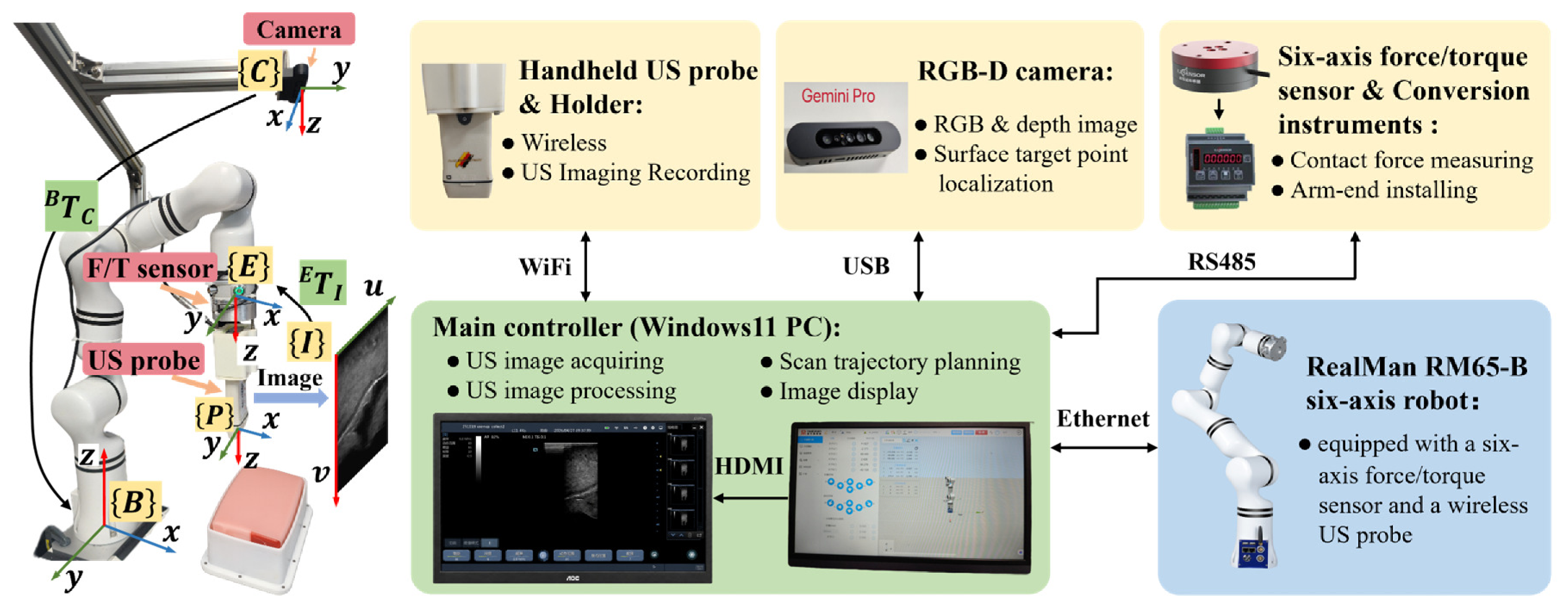
The proposed autonomous robotic ultrasound system consists of four main modules: a six-degree-of-freedom robotic arm (RM65-B, RealMan, Beijing, China), a six-axis force/torque sensor (XJC-6F-D40-H18-A, XJCSENSOR, Shenzhen, China), an RGB-D camera (Gemini Pro, ORBBEC, Shenzhen, China), and a commercial handheld wireless ultrasound probe (D8c, Youkey Medical, Wuhan, China). The overall configuration of the system is shown in
Figure 1.
The robotic arm communicates with the main control computer through a wired Ethernet connection using the UDP protocol. This communication channel is used for transmitting robot control commands and receiving robot state information. The six-axis force/torque sensor is mounted at the robot end effector through a flange and connected to an XJC-620F-6 conversion instrument. It measures the force components along the X, Y, and Z axes and the torque components around these axes. The measurement ranges are ±20 N for force and ±1 N·m for torque, with resolutions of 0.002 N and N·m, respectively. The nonlinearity and hysteresis errors are both within ±0.5% F.S., and the repeatability error is within ±0.05% F.S. The conversion instrument acquires the force/torque measurements at 100 Hz and transmits them to the main control computer through an RS485 serial communication interface. The ultrasound probe is connected to the force/torque sensor through a customized probe holder. The holder is designed with a buffering mechanism to reduce instantaneous impacts that may occur during robot motion and to improve the stability of probe-skin contact. With this configuration, the force/torque sensor can directly measure the interaction force and torque between the ultrasound probe and the body surface during scanning. The ultrasound probe communicates with the main control computer via WiFi, and B-mode ultrasound images are acquired and recorded using the dedicated ultrasound application SonoiQ. The operating frequency range of the probe is 6–11 MHz, which is suitable for musculoskeletal ultrasound imaging. The RGB-D camera is installed above the robotic workspace in an eye-to-hand configuration. It is used to acquire RGB and depth images of the scanning region and to estimate the position of the body-surface target point.
The main controller of the system is a personal computer (Intel i7-13620H, CPU @ 2.40 GHz, 16 GB RAM), which is mainly responsible for robot control, data acquisition, image segmentation, and scan trajectory planning. The related functions were developed based on Visual Studio Code 1.106.2, and the software environment was managed using Anaconda to improve system stability and reproducibility.
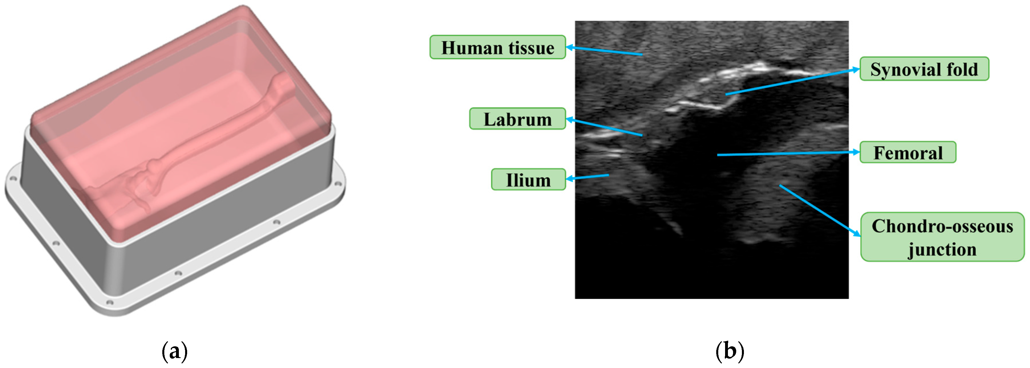
Considering the safety and ethical limitations of directly conducting experiments on infant subjects, a customized hip gelatin phantom was first used as the experimental object in this study to construct a repeatable experimental scenario for infant hip examination. The phantom has skin-like softness in its external appearance, allowing stable contact and continuous scanning with the robotic ultrasound probe. Meanwhile, its internal structure was designed to present key anatomical structures related to the Graf standard plane in ultrasound imaging, including the ilium, femoral, labrum, chondro-osseous junction and synovial fold, as shown in
Figure 2.
2.2. System Calibrations
In the proposed robotic system, calibration is required to unify the coordinate frames and measurement references of different modules. The calibration mainly includes coordinate calibration and gravity compensation calibration. Coordinate calibration consists of ultrasound image-to-robot calibration and RGB-D camera-to-robot calibration, while gravity compensation calibration is used to remove the influence of the end-effector weight and sensor offset on force measurement.
2.2.1. Ultrasound Image Calibration
Ultrasound image calibration is performed to determine the transformation matrix
from the ultrasound image coordinate frame
to the robot end-effector coordinate frame
, together with the scale matrix
for converting pixel dimensions into physical dimensions. Following the method in [
27], these parameters are estimated by minimizing the position error of the calibration feature points:
where
denotes the end-effector pose relative to the robot base frame when the
-th image is acquired, while
and
denote the corresponding calibration feature points in the ultrasound image and robot base coordinate frames, respectively.
After calibration, any pixel point
can be mapped to the robot base coordinate frame as:
This transformation is used to convert ultrasound image features into robot coordinates for image-guided probe adjustment.
2.2.2. RGB-D Camera-to-Robot Calibration
RGB-D camera-to-robot calibration is performed to determine the transformation matrix
from the RGB-D camera coordinate frame
to the robot base coordinate frame
. Since the camera is fixed in an eye-to-hand configuration,
remains constant after calibration and is estimated using the classical hand-eye calibration method [
28].
After calibration, a point
acquired by the RGB-D camera can be transformed into the robot base coordinate frame as:
For a target pixel
with the corresponding depth
, its three-dimensional coordinate in the camera coordinate frame is calculated as:
where
and
are the focal lengths of the camera;
and
are the principal point coordinates of the RGB-D camera.
Equations (3) and (4) are used to convert the selected body-surface target point into the robot base coordinate frame for initial probe positioning.
2.2.3. Gravity Compensation Calibration
Gravity compensation calibration is performed to remove the effects of the end-effector tool gravity and sensor zero offset from the raw force/torque measurements. Since the robotic ultrasound scanning process is performed at a low speed, the inertial force of the end-effector tool is neglected. The force/torque sensor coordinate frame is aligned with the robot end-effector coordinate frame, and its pose can therefore be obtained directly from the robot end-effector pose.
Let the robot base coordinate frame be
. The compensated contact force is calculated as:
where
denotes the raw force measured by the sensor,
denotes the actual contact force,
denotes the gravity component of the end-effector tool in the sensor coordinate frame, and
denotes the sensor zero offset.
Since gravity has a fixed direction in the robot base coordinate frame, its component in the sensor coordinate frame is calculated as:
where
denotes the total weight of the ultrasound probe, probe holder, and end-effector connector, and
is the rotation matrix from the robot base coordinate frame to the sensor coordinate frame.
During calibration, force measurements are collected at multiple end-effector poses while the ultrasound probe remains free from external contact, such that
. The end-effector tool weight
and sensor zero offset
are then estimated using the least-squares method:
After calibration, is calculated in real time according to the current robot end-effector pose, and the compensated contact force is obtained using Equation (5) for subsequent contact force control. After compensation, the RMSE values of , , and were 0.0834, 0.0455, and 0.0571 N, respectively. The RMSE values of , , and were , , and N·m, respectively.
2.3. Contact Force Compliance Control
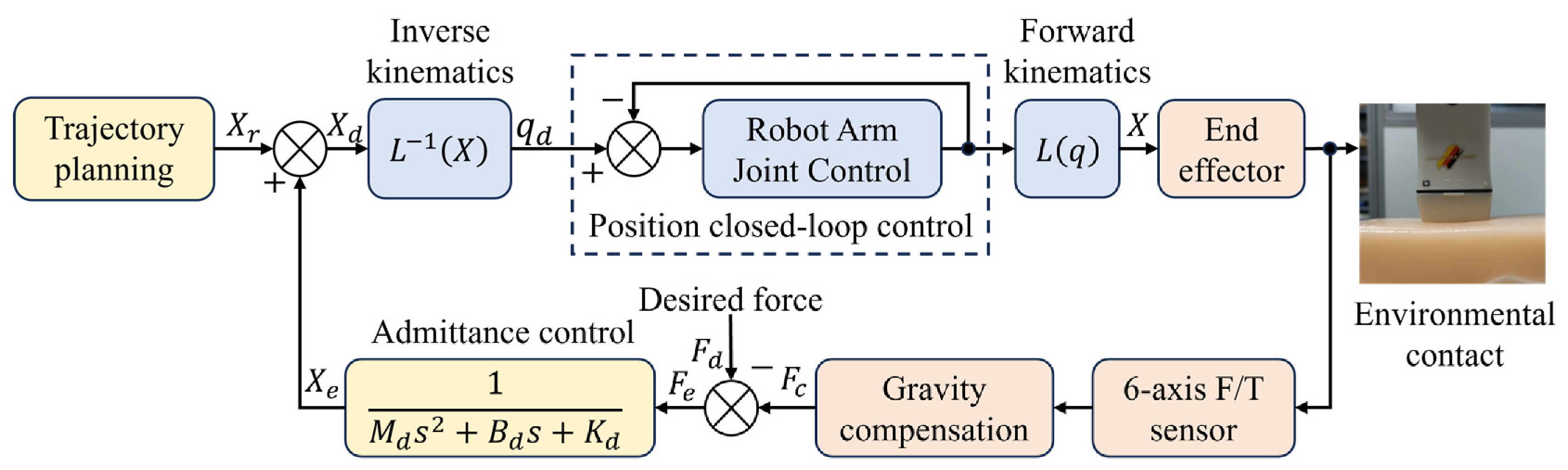
An admittance-based hybrid force/position control method was adopted to maintain stable probe-surface contact during scanning, as shown in
Figure 3. The tangential motion of the probe followed the planned scanning trajectory, while its position along the surface-normal direction was adjusted according to the contact force error. The detailed control method has been presented in our previous work [
29].
The normal displacement correction was generated using a second-order admittance model:
where
is the displacement correction generated by the admittance controller, and
and
are its velocity and acceleration.
The admittance parameters were empirically tuned on the infant hip phantom. The virtual mass was first fixed to limit rapid probe acceleration. The stiffness was then gradually increased to reduce excessive displacement while maintaining sufficient compliance. Finally, the damping coefficient was adjusted to suppress force oscillations without causing an overly slow response. Based on repeated contact and scanning experiments, the parameters were set to , , and .
A Kalman filter was applied to the measured force signal to reduce measurement noise [
29]. The admittance controller was executed at 50 Hz with a control period of
. The resulting normal displacement correction was superimposed on the planned scanning trajectory and sent to the robot controller.
To ensure safety, contact force thresholds are set. When the contact force exceeds 6 N, the robot pauses scanning and retracts along the normal direction. If the force remains excessive or exceeds 10 N, the scanning process is terminated and the robot returns to the initial safe pose.
2.4. Feature Extraction of Ultrasound Image
Ultrasound image features provide the basis for Graf standard plane searching. In this study, semantic segmentation is used to extract target structures from ultrasound images. All input images are two-dimensional B-mode ultrasound images with a size of 256 × 256 pixels.
SegNeXt is adopted as the basic segmentation network. Its lightweight convolutional design and multi-scale feature modeling enable efficient extraction of tissue boundaries and local structural features in ultrasound images with low computational cost [
30,
31]. To meet the different requirements for inference speed and segmentation accuracy at different stages, two SegNeXt-based networks are trained. Both networks use an encoder–decoder structure and MSCAN as the feature extraction backbone, but they differ in encoder size, output classes, and application stages.
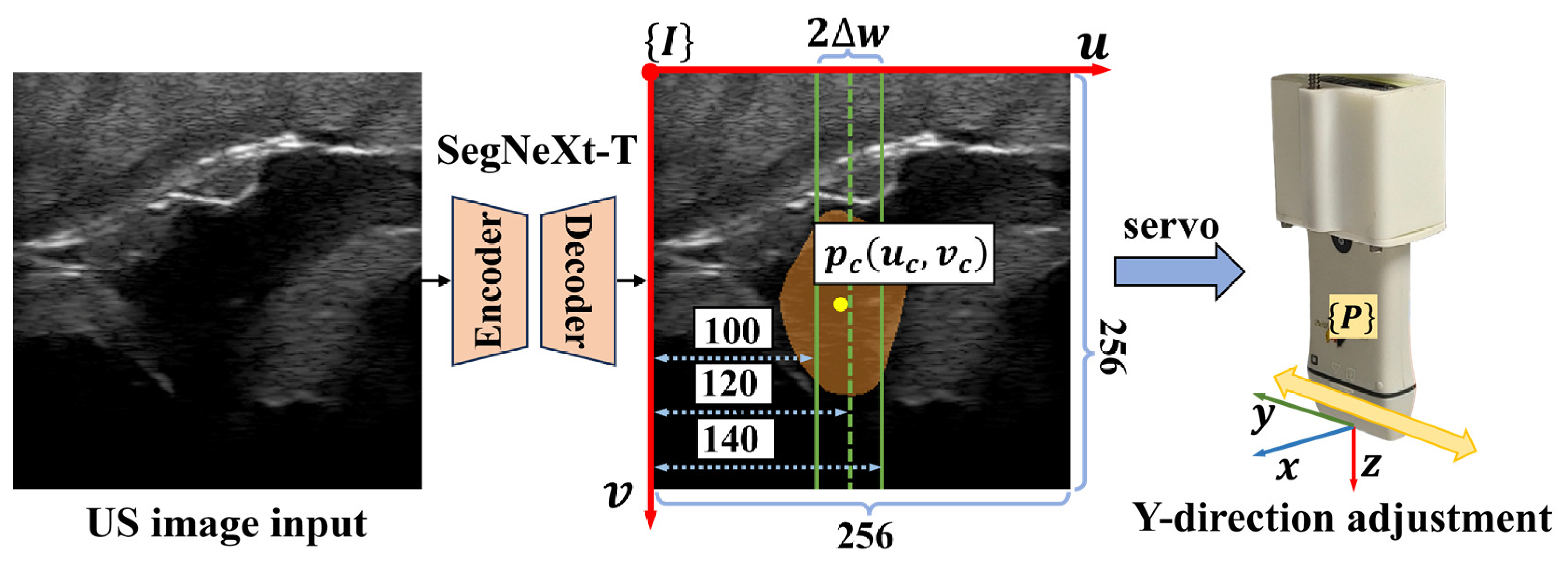
The first network is SegNeXt-T, which is used for femoral head segmentation during the searching stage. It uses the lightweight MSCAN-T backbone and outputs a binary segmentation result of the background and femoral head. Based on the segmentation mask, the pixel area and center position of the femoral head are extracted. The femoral head region is defined as:
where
denotes the class predicted by SegNeXt-T for pixel
, and
indicates that the pixel belongs to the femoral head region.
The pixel area of the femoral head is calculated as:
The center pixel coordinates
of the femoral head is then calculated by averaging the coordinates of all pixels within the segmented region:
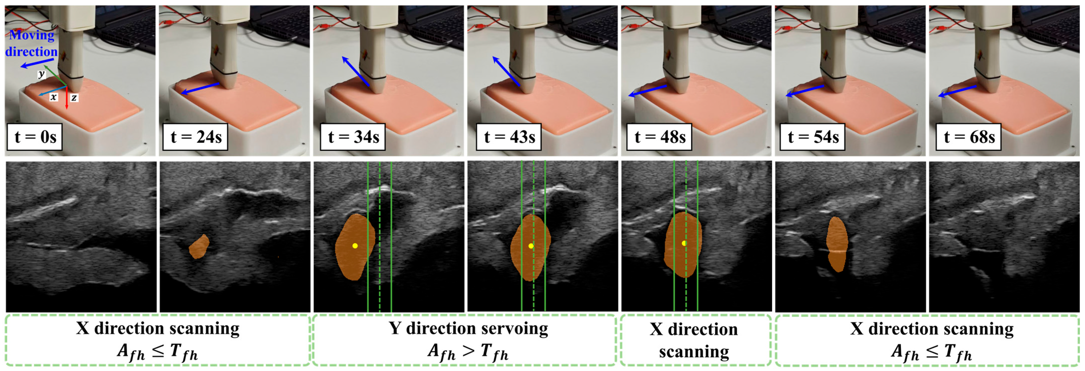
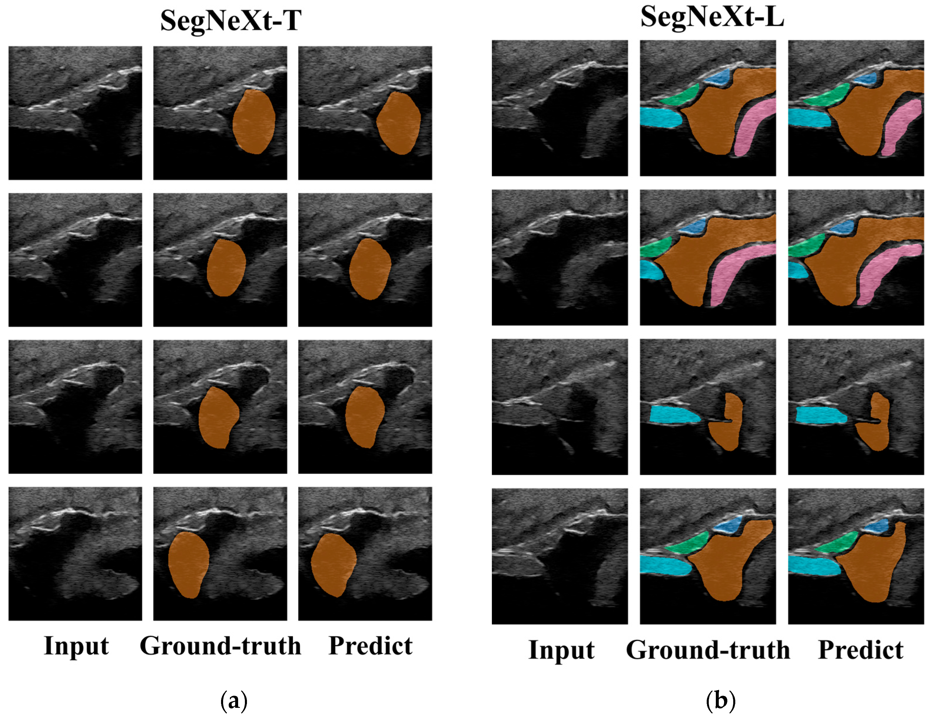
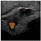
The pixel area is used to determine whether the femoral head is visible, while the center position provides visual feedback for probe adjustment, as shown in
Figure 4. Since rapid image feedback is required in this stage, SegNeXt-T is selected due to its smaller model size and faster inference speed.
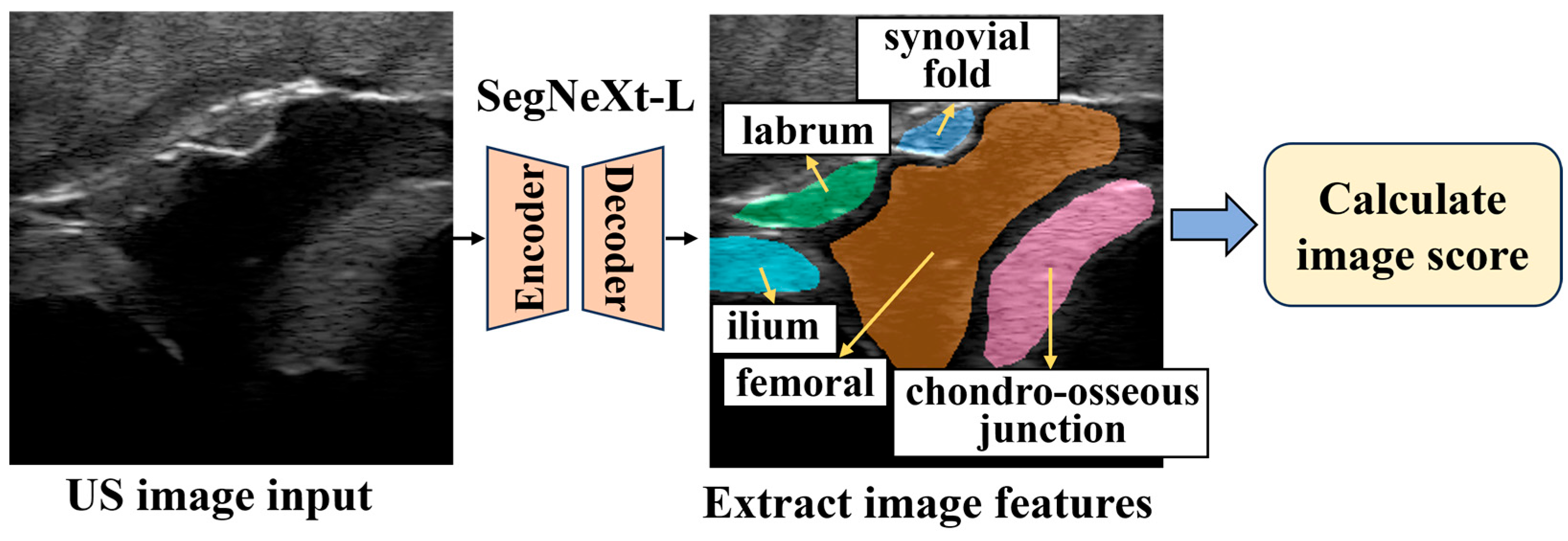
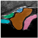
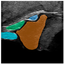
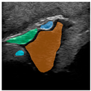
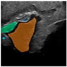
The second network is SegNeXt-L, which is used for multi-structure segmentation of candidate Graf standard plane images. After femoral head localization, the robot performs local scanning around the selected position and acquires a series of candidate ultrasound images. These images are then input into SegNeXt-L for semantic segmentation, as shown in
Figure 5. The foreground classes include the chondro-osseous junction, femoral, ilium, labrum, and synovial fold. Compared with SegNeXt-T, SegNeXt-L has a larger encoder and stronger feature representation ability, and is therefore used for fine segmentation of multiple anatomical structures in the Graf standard plane.
For the
-th foreground anatomical structure, its segmented region is defined as:
where
denotes the predicted class of pixel
. The pixel area of the corresponding structure is calculated from
and defined as:
In this study, the pixel areas of the foreground structures are used as the main features for Graf standard plane scoring, reflecting the visibility and completeness of key anatomical structures in the image. These area features are then input into the scoring mechanism to select the image with the highest score as the optimal Graf standard plane.
In summary, SegNeXt-T and SegNeXt-L are used to construct a two-stage ultrasound image feature extraction method. SegNeXt-T focuses on rapid femoral head localization during the searching stage, whereas SegNeXt-L focuses on accurate anatomical structure extraction from candidate standard plane images. This design balances real-time performance in the searching stage and segmentation accuracy in the standard plane selection stage, providing the basis for subsequent image-guided servo control and standard plane scoring.
2.5. Dataset Construction and Training
Based on the hip phantom, two ultrasound image datasets were constructed to train the two SegNeXt-based segmentation networks described in
Section 2.4. The first dataset was used for femoral head segmentation, in which the femoral head region was manually annotated at the pixel level. This dataset contained 390 ultrasound images and was divided into training and validation sets at a ratio of 8:2, with 312 images for training and 78 images for validation. The second dataset was used for multi-structure segmentation. Five foreground anatomical structures were manually annotated, including the chondro-osseous junction, femoral, ilium, labrum, and synovial fold. This dataset contained 576 ultrasound images and was also divided at a ratio of 8:2, with 461 images for training and 115 images for validation. All input images were resized to 256 × 256 pixels.
The training settings of the two datasets were kept consistent, except for the number of output classes. The models were implemented using PyTorch 2.1.0 and trained on an NVIDIA GeForce RTX 3080 GPU. During training, random scaling, random cropping, random flipping, and Gaussian noise were used for data augmentation to improve the robustness of the models to probe pose changes, noise artifacts, and local structural variations. The batch size was set to 4, and the maximum number of training iterations was set to 10,000. Model performance was evaluated on the validation set every 1000 iterations. In each iteration, the model was updated using one batch of data. The model with the best validation performance was saved for subsequent robotic standard plane searching experiments.
The loss function was defined as a combination of cross-entropy loss and Dice loss:
Cross-entropy loss was used to improve pixel-level classification accuracy, while Dice loss was used to increase the overlap between the predicted regions and manual annotations. This combination helps reduce the influence of small foreground structures and class imbalance in ultrasound images.
The cross-entropy loss is defined as:
where
denotes the total number of pixels,
denotes the number of classes,
denotes the ground-truth label of the
-th pixel for class
, and
denotes the predicted probability that the
-th pixel belongs to class
.
The Dice loss is defined as:
where
is a smoothing term used to avoid division by zero.
AdamW was used as the optimizer, with an initial learning rate of
and a weight decay of 0.01. A learning rate scheduling strategy combining linear warm-up and polynomial decay was adopted. In the early training stage, LinearLR gradually increased the learning rate to the initial value to improve training stability. After warm-up, PolyLR gradually decayed the learning rate according to the number of iterations, as follows:
where
is the learning rate at the
-th iteration,
is the initial learning rate,
is the maximum number of iterations, and
is the polynomial decay coefficient. In this study,
was set to
, so the learning rate approximately decayed linearly to 0 during training.
2.6. Graf Standard Plane Search Strategy
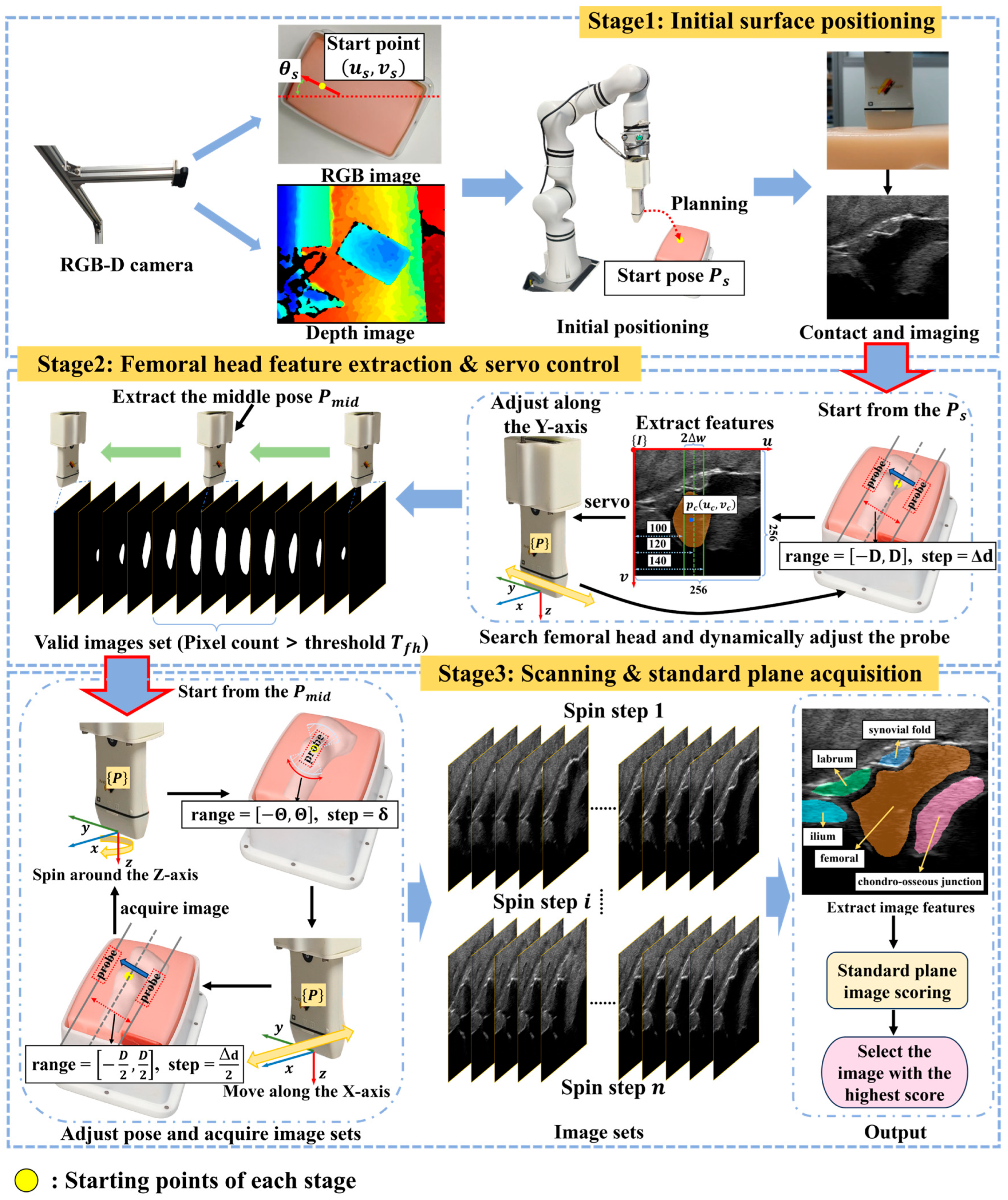
To automatically acquire the Graf standard plane of the infant hip, a three-stage search strategy is designed, as shown in
Figure 6. This strategy mimics the coarse-to-fine scanning process used by sonographers, progressively narrowing the search region based on anatomical features. Since the Graf standard plane is visible only within a limited range of probe poses, exhaustive scanning is inefficient. The strategy first uses the RGB-D camera for initial surface positioning, then searches for the femoral head center based on segmentation results, and finally performs multi-angle scanning around the femoral head center. The image with the highest score given by the scoring mechanism is selected as the optimal Graf standard plane. Throughout the contact process with the phantom, the robot ensures scanning safety and stable contact force using the compliant control method described in
Section 2.3.
2.6.1. Initial Surface Positioning
The first stage is initial surface positioning. The RGB-D camera first acquires RGB and depth images of the phantom surface. Then, the operator selects an initial scanning point near the Graf standard plane region in the RGB image and gives the initial probe direction. This step does not require precise localization or professional skills. Let the manually selected pixel point be
. Its 3D coordinate
in the camera frame
can be obtained from the depth image. According to the calibration relationship in
Section 2.2.2, this point is transformed into the robot base frame
:
The initial probe pose is then determined according to the selected scanning direction, and the initial end-effector pose
is generated. The robot moves to this pose, as shown in Stage 1 of
Figure 6. After the probe contacts the body surface and the contact force becomes stable, the system enters the second stage.
2.6.2. Femoral Head Searching
The second stage aims to search for the femoral head region near the initial positioning point and determine its center along the scanning direction. Taking the contact pose obtained in the first stage as the center, the robot plans a scanning trajectory along the x-direction. The scanning range is set to
, with a step size of
. At each sampling position, the system acquires one ultrasound image. After segmentation, the pixel area
and center position
of the femoral head region are calculated. When
, the current image is considered to contain a valid femoral head region. At this stage, servo adjustments are performed during scanning according to the horizontal coordinate deviation between
and the desired position. Specifically, the desired horizontal pixel range is set to
. When
is outside this range, the horizontal pixel deviation is calculated as
, and is then converted into the actual physical displacement
. This displacement is used to guide the servo adjustment of the probe along the
-direction. Valid images and their corresponding end-effector poses are continuously recorded as long as the femoral head remains visible. When the femoral head region disappears or its pixel area falls below the threshold, the scan is terminated, as shown in Stage 2 of
Figure 6. Finally, the middle pose
is selected from the continuous valid pose sequence as the starting point for the third stage.
2.6.3. Multi-Angle Scanning and Image Screening
The third stage performs multi-angle scanning around the selected starting point
and screens the image closest to the Graf standard plane, as shown in Stage 3 of
Figure 6. The robot first rotates the probe around its local
-axis within a preset angular range
, with an angular step of
. At each rotation angle, the probe performs a small-range translation along its
-axis. At each sampling position, one ultrasound image is acquired. After all rotation and translation scans are completed, a candidate image set is obtained. All candidate images are then input into the SegNeXt-L network described in
Section 2.4 to segment five anatomical structures, including the chondro-osseous junction, femoral, ilium, labrum, and synovial fold. The pixel area features of each structure are then extracted.
To evaluate how close each candidate image is to the Graf standard plane, the standard plane scoring mechanism is constructed based on the presence and completeness of each structure.
First, connected-component analysis is performed on the segmentation results of the five structures in each image. For the
-th structure in the
-th image, if the segmentation result contains only one valid connected region and its pixel area is larger than the corresponding threshold
, the structure is considered validly present in the current image:
where
denotes the number of valid connected regions of the
-th structure in the
-th image,
denotes its pixel area, and
is the minimum area threshold of the corresponding structure.
Based on the presence of the five structures, the total presence score is defined as:
where
is the scoring weight of the
-th structure.
Next, to evaluate the display completeness of each foreground structure in the image, a maximum reference pixel area
is set for each structure. The area completeness ratio of the
-th structure in the
-th image is defined as:
Based on the area completeness ratios of the five structures, the total completeness score is defined as:
Finally, the total score of the
-th candidate image is defined as:
Thus, the closer the score is to 1, the more consistent the image is with the Graf standard plane. The ultrasound image with the highest score is finally selected as the output, completing the entire search process.
4. Discussion
The experimental results demonstrate the preliminary feasibility of the proposed autonomous robotic ultrasound system for Graf standard plane acquisition. By integrating stage-wise robotic searching, ultrasound image segmentation, multi-structure scoring, and compliant force control, the system achieved a Graf standard plane acquisition success rate of 90.0% while maintaining stable probe–phantom contact. These results indicate that the proposed framework can reduce dependence on operator experience and improve the consistency of standard plane acquisition.
Nevertheless, this study has several limitations. First, the experiments were mainly conducted on a stationary hip phantom. Differences between the phantom and real infants in anatomical structure, ultrasound appearance, and tissue mechanical properties may affect segmentation and force-control performance. Involuntary infant motion may also disturb probe–skin contact and cause the target anatomy to move outside the predefined search region. Second, the initial scanning point and probe direction were still manually specified, meaning that the current system has not yet achieved complete autonomy. Third, the segmentation datasets and scoring thresholds were established primarily from phantom data, and their generalizability to different subjects and clinical conditions remains to be evaluated. Finally, the present system focuses on Graf standard plane acquisition and does not yet include automatic angle measurement or DDH classification.
Future work will focus on improving system autonomy, robustness, and clinical applicability. Automated initial localization and motion compensation methods will be investigated to reduce manual intervention and improve performance under dynamic conditions. Clinical ultrasound datasets will be expanded to improve model generalization, followed by human-subject studies comparing robotic and sonographer-acquired standard planes. Automatic measurement of the α and β angles will also be integrated to establish a complete workflow from autonomous standard plane acquisition to computer-assisted DDH assessment.
5. Conclusions
This study developed an autonomous robotic ultrasound system to address the dependence on experienced operators and the limited consistency and repeatability in hip ultrasound examination. The system integrates RGB-D visual localization, contact force control, and ultrasound image segmentation. Based on system calibration, a hybrid force/position control method based on admittance control was used to maintain stable contact while the probe moved along the planned trajectory. For Graf standard plane acquisition, a three-stage search strategy was designed, including initial body surface positioning, femoral head search, and local multi angle scanning. The system uses SegNeXt-T to extract femoral head features and SegNeXt-L to segment five anatomical structures in candidate images. Combined with a multi structure scoring mechanism, the optimal Graf standard plane image can be automatically selected.
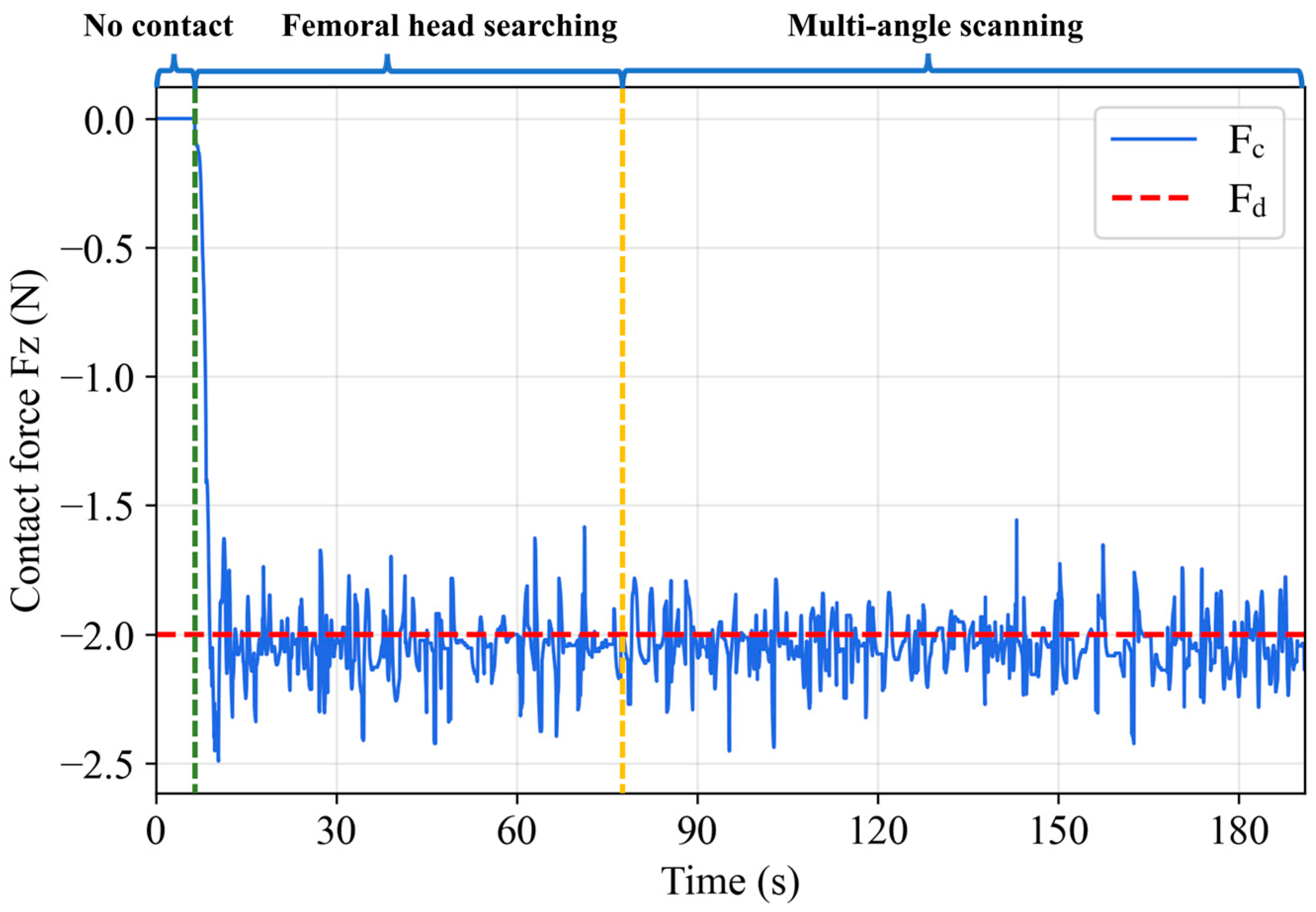
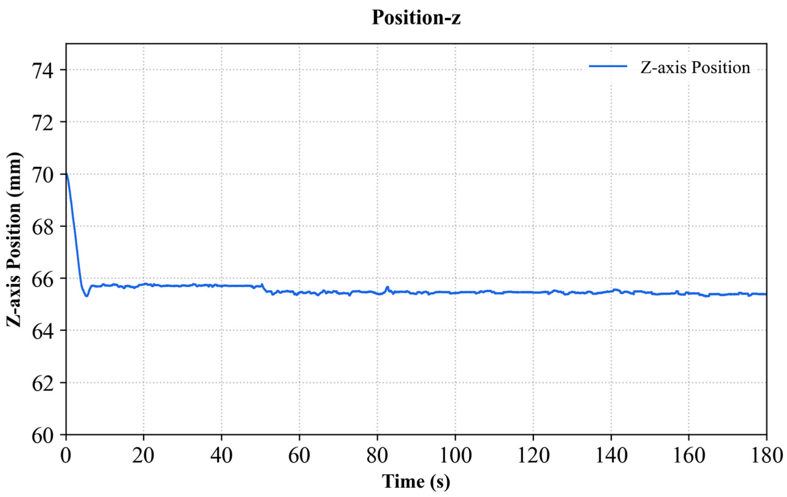
The proposed system was preliminarily validated on a customized hip phantom. The experimental results showed that SegNeXt-T achieved a Dice coefficient of 0.872 for femoral head segmentation, and SegNeXt-L achieved a mean Dice coefficient of 0.866 for the five anatomical structures. In 30 autonomous search trials under different initial conditions, the system successfully acquired the Graf standard plane in 27 trials, with an overall success rate of 90.0%. During scanning, the normal contact force ranged from −2.492 to −1.517 N, with a mean value of −2.045 N, a root mean square error of 0.229 N, and a standard deviation of 0.213 N. These results indicate that, after a coarse initial position and probe direction are manually provided, the robot can autonomously complete the subsequent search and maintain stable contact during scanning. This study provides a feasible approach for reducing the dependence of hip ultrasound scanning on operator experience and improving the consistency and repeatability of Graf standard plane acquisition.