Article

Modeling the Interaction of Pulsed EHD Forces and Aerodynamic Shielding on Sub-Micron Particles

by
Aleksandr Šabanovič
1,
Jonas Matijošius
2 and
Piotr Jaskowski
3,*
1
Department of Mechanical and Material Engineering, Faculty of Mechanics, Vilnius Gediminas Technical University-VILNIUS TECH, Plytinės str. 25, LT-10105 Vilnius, Lithuania
2
Mechanical Science Institute, Vilnius Gediminas Technical University-VILNIUS TECH, Plytinės str. 25, LT-10105 Vilnius, Lithuania
3
Faculty of Transport, Warsaw University of Technology, Koszykowa 75, 00-662 Warszawa, Poland
*
Author to whom correspondence should be addressed.
Actuators 2026, 15(7), 405; https://doi.org/10.3390/act15070405
Submission received: 28 May 2026 / Revised: 13 July 2026 / Accepted: 18 July 2026 / Published: 20 July 2026
(This article belongs to the Special Issue Design, Hydrodynamics, and Control of Mechatronic Systems)

Abstract

Electrohydrodynamic (EHD) actuators offer a promising approach for active particulate matter (PM) control in heavy-duty and marine exhaust systems. However, continuous DC corona discharge often leads to excessive energy consumption and is susceptible to aerodynamic re-entrainment in high-velocity flows. This study introduces an idealized transient advection mechanism combining a macroscopic corrugated duct geometry with high-frequency pulsed EHD actuation. A fully coupled, time-dependent multiphysics model—integrating RANS turbulent flow, Poisson-Nernst-Planck space charge transport, and Lagrangian discrete particle tracing—was developed to analyze the physical kinetics of 0.2 µm soot particles. The results demonstrate that the corrugation troughs act as effective aerodynamic dead zones with partial electrostatic shielding, creating aerodynamic and electrostatic dead zones. During active microsecond voltage pulses (25 kV peak), intense Coulombic forces rapidly overcome turbulent drag, driving kinetic injection of particles into the corrugation troughs. During the resting phase, particles remain securely trapped by aerodynamic shielding, significantly mitigating the risk of aerodynamic re-entrainment under the simulated conditions. A comprehensive parametric analysis revealed that an optimized 500 Hz pulse with a 5% duty cycle maintains a robust 82.7% trapping efficiency. Compared to standard continuous DC precipitators, this pulsed actuation strategy requires an idealized active corona power of 15.3 mW. This study provides fundamental physical insights into transient EHD flows and establishes optimized design criteria for fundamental EHD transport models.

1. Introduction

Electrohydrodynamic (EHD) phenomena have attracted significant scientific attention in recent years due to their ability to directly control flows, charged particles and aerosols without mechanical moving components [1,2]. Such systems are characterized by low pressure loss, the ability to operate in difficult operating conditions and high energy efficiency, therefore they are promising in the fields of transport, energy, air purification and emission control. Particular attention is paid to pulsed corona discharge systems, in which transient electric fields allow for the efficient generation of ion flows and control of the kinetics of submicron particles [3].
The operation of EHD systems is based on the interaction of an electric field and a liquid or gas, when electrical forces are directly transformed into hydrodynamic flows [4,5]. Early research mainly focused on stationary direct current (DC) corona discharges, but later work has shown that the pulsed regime allows for significantly more effective control of ionization processes and reduced energy consumption. Studies have shown that high-frequency pulsed electrical signals form extremely intense short-term EHD pulses, which generate large local electrohydrodynamic body force fields and transient ionic fluxes [6]. Such transient processes are particularly important for particle injection into collector surfaces and for reducing the re-entrainment phenomenon.
Pulsed EHD systems are becoming increasingly relevant in particulate control in the transport and energy sectors [7,8]. Conventional electrostatic precipitators typically draw a lot of power and struggle with particle re-entrainment when exposed to turbulent flows. Studies have shown that pulsed modes allow maintaining high particle collection efficiency while significantly reducing average energy consumption [9]. It has been established that the efficiency of particle collection is determined not only by the electric field strength, but also by the flow structure, geometry, particle residence time and turbulent vortices [10].
One of the most important aspects of modern research is the modeling of transient EHD flows. Many authors emphasize that the interaction of transient electric fields, ion migration and turbulent hydrodynamics is an extremely complex multiphysics problem that requires fully coupled models. Such models usually combine the Navier–Stokes equations, Poisson–Nernst–Planck charge transport models and Lagrangian particle tracking methods [11]. Studies show that transient EHD phenomena strongly depend on the charge relaxation time, electric field heterogeneity and the formation of local vortex structures [12,13].
The influence of pulsed electrical signals on EHD systems is widely studied in other areas as well. Work with sinusoidal AC signals shows that, at certain frequencies and viscosities, the fluid’s oscillation mode can jump from double harmonic to synchronous behavior—a transition that appears to be quite sensitive to both parameters [3]. Fourier analysis has revealed complex multiharmonic behavior, indicating strong nonlinear electrohydrodynamic effects. Such results confirm that transient electric fields can be used for directional control of flows and particles [14,15].
An important research direction is the influence of electrode geometry on EHD flows. It has been found that even small changes in geometry can radically change the structure of the electric field, ion migration and turbulence distribution [16]. Symmetrical electrode systems generate stable vortex flows, while asymmetric geometries can cause chaotic turbulence and local instability zones. This is especially important when designing EHD collectors, where it is necessary to ensure both high particle collection and minimal pressure drop.
Considerable attention is also paid to the aerodynamic shielding effect. It has been found that specific conductive geometries can form electrostatic “death zones” where the electric field intensity is significantly reduced and the particles become protected from the main turbulent flow [17]. Such effects are of great importance for reducing re-entrainment in high-velocity exhaust systems. Studies in gas isolation systems have also shown that the geometry of particle traps allows optimizing the electric field distribution and increasing local collection efficiency [18].
Particle kinetics in electric fields is closely related to aerosol physics. Aerosol particle transport depends on Stokes drag, Coulomb forces, turbulent diffusion and electrostatic aggregation processes. Experimental studies have shown that fine particles are extremely sensitive to surface charge, and surface electrification significantly changes their optical and aerodynamic properties [19]. Such phenomena are important for both electrostatic deposition and aerosol monitoring systems.
Pulsed corona discharges are also actively used in non-thermal plasma technologies. Studies show that short nanosecond pulses allow for the efficient generation of reactive particles and at the same time limit electrode degradation and thermal losses [20]. Such systems are particularly relevant for exhaust gas cleaning, as they allow for the simultaneous reduction in both NOx and particulate emissions.
The interaction of turbulent flows and particles remains one of the most complex problems. Studies of cyclonic separators have revealed that vortex structures, recirculation zones and secondary flows directly determine the residence time and deposition efficiency of particles [21]. Similar phenomena are observed in EHD collectors, where electric fields additionally modify the vortex structures. It has been found that transient pulsed regimes can create local “kinetic injection” mechanisms, when particles are pushed into the collector cavities by short intense pulses.
The problem of particle re-entrainment is particularly relevant in high-velocity exhaust systems. Studies with coal dust and soot aerosols have shown that turbulent shear stresses can cause secondary particle lift even after successful deposition [22]. Therefore, modern collectors are designed to form aerodynamic “quiet zones” where particles remain isolated from the main flow.
Energy efficiency of EHD systems is becoming one of the most important research directions. Many authors emphasize that pulsed modes allow for a significant reduction in average energy consumption while maintaining high collection efficiency [9]. This is especially relevant for marine and heavy transport engines, where energy losses are directly related to fuel consumption and CO2 emissions [23].
Modern multiphysics models increasingly integrate artificial intelligence methods and data-driven optimization strategies. The research emphasizes that machine learning algorithms can be used to predict transient EHD processes and search for optimal parameters [24]. Such methods are particularly promising for designing new generation adaptive EHD systems.
Many authors also emphasize that experimental study of transient EHD phenomena remains difficult due to very fast processes and strong electric fields. Therefore, PIV (Particle Image Velocimetry) techniques are widely used, allowing visualization of ion fluxes and particle trajectories [25]. However, even these technologies face limitations due to large velocity gradients and low signal-to-noise ratio [26].
From an environmental point of view, EHD technologies are considered one of the most promising directions for reducing fine particle emissions. The impact of bioaerosols, PM2.5 and ultrafine particles on human health is associated with respiratory, cardiac and neurological diseases [27]. Therefore, electrostatic systems with high efficiency, low energy consumption and low pressure loss are becoming extremely important in the future transport and energy infrastructure [28].
Recent scientific research clearly shows the transition from stationary DC electrostatic systems to transient pulsed EHD activation methods. These systems allow for effective control of ion fluxes, reduce energy consumption, suppress re-entrainment phenomena and increase the efficiency of submicron particle collection. However, important challenges remain related to the modeling of transient multiphysics processes, control of turbulent hydrodynamics and the development of optimal collector geometries [29]. That is why corrugated collectors based on aerodynamic and partial electrostatic shielding principles, together with pulsed corona discharges, are considered one of the most promising directions in developing a new generation of energy-efficient emission control systems.
The control of particulate matter (PM) emissions from heavy-duty and marine exhaust systems remains a critical environmental challenge. Conventional filtration technologies, such as passive diesel particulate filters (DPFs), suffer from severe pressure drops and require complex active regeneration cycles. In recent years, active electrostatic and cold plasma technologies have emerged as highly promising alternatives for continuous, low-back-pressure emission control. Electrohydrodynamics (EHD), which studies the interaction between electric fields and fluid motion, provides a mechanism for manipulating charged particles directly without mechanical barriers [30,31]. Over the years, EHD actuators have found use in a surprisingly wide range of applications, from tiny microsystem pumps to full-scale air cleaning units [32].
What ties all of them together is the corona discharge—the process responsible for ionizing the surrounding gas and forming a non-thermal plasma (NTP). Standard electrostatic precipitators (ESPs) typically depend on a continuous DC corona to capture particles. However, this approach draws a considerable amount of energy and often struggles with aerodynamic re-entrainment when faced with fast, turbulent flows [33,34]. As a practical workaround, researchers have increasingly turned to pulsed corona discharge (PCD). By firing intense plasma pulses lasting just nanoseconds to microseconds, PCD produces both reactive species and robust EHD forces. This makes it possible to strip away particulate matter and gaseous pollutants like NOx simultaneously, all while keeping power usage remarkably low [35,36]. Beyond energy savings, the transient behavior of these pulses gives us a much more dynamic way to control the resulting EHD flow and ionic wind—a key factor in driving particles efficiently toward the collector walls [37,38].
That said, simply switching to pulsed actuation is not enough to guarantee high capture rates in heavy-duty exhaust systems; the physical geometry has to evolve as well. As recent numerical and experimental work on transient EHD flows has pointed out, accurately capturing the interplay between rapidly shifting electric fields and chaotic fluid turbulence remains a formidable challenge [39,40].
Specifically, preventing the re-entrainment of ultrafine particles back into the main gas stream remains a major hurdle. Recent advances in gas-insulated systems demonstrate that specific structural parameters in particle traps can optimize the electric field distribution to enhance capture efficiency [41,42]. Inspired by these findings, we look toward aerodynamic shielding as a practical solution. Incorporating specific conductive features, like wall corrugations, allows us to form aerodynamic and electrostatic “dead zones” (essentially providing partial electrostatic shielding) aerodynamic dead zones with partial electrostatic shielding) that protect trapped matter from being swept away by the high-speed exhaust flow [43].
Consequently, this paper introduces a novel trapping mechanism designed around the synergy of macroscopic corrugations and a fast 1 kHz pulsed EHD signal. To explore the complex, transient kinetics of sub-micron soot inside this system, we developed a fully coupled multiphysics model that captures the time-dependent behavior in high detail. By shifting from continuous DC to a pulsed EHD strategy and employing aerodynamically shielded corrugations, this research aims to demonstrate the fundamental mathematical mechanics of EHD-induced particle advection.

2. Materials and Methods

2.1. Geometry and Computational Domain

The computational domain consists of a 2D axisymmetric representation of a cylindrical exhaust duct featuring an inner corona wire and an externally corrugated collecting wall. The internal wire serves as the high-voltage discharge electrode, while the outer corrugated wall functions as the grounded collection surface. Specifically, the modeled duct has an inner radius of 75 mm and a total length of 1600 mm. The corona wire has a radius of 0.15 mm. The geometric corrugations are modeled as a sinusoidal wave with a wavelength (pitch) of 20 mm and a depth (amplitude) of 5 mm. These dimensions are deliberately selected to act as macroscopic aerodynamic dead zones with partial electrostatic shielding, creating localized aerodynamic and electrostatic dead zones to trap sub-micron particulate matter.

2.2. Time-Dependent Multiphysics Modeling

To accurately capture the highly transient phenomena of pulsed EHD actuation, a fully coupled time-dependent multiphysics approach was employed. Rather than relying on steady-state approximations or unphysical manual equation smoothing, the model fundamentally integrates circuit-coupled fluid dynamics, charge transport, and discrete particle kinetics to evaluate the system’s true physical behavior.

2.2.1. Turbulent Flow and EHD Coupling

The primary exhaust gas velocity field is determined by solving the Reynolds-Averaged Navier–Stokes (RANS) equations alongside the continuity equation for an incompressible fluid using the standard k ϵ turbulence model at a specified exhaust temperature of 300 °C:
ρ U U = p + μ + μ t U + U T + F E H D
ρ U = 0
where ρ is the fluid density, U is the mean velocity vector, p is pressure, μ is dynamic viscosity, μ t is turbulent eddy viscosity, and F E H D is the electrohydrodynamic body force. The critical physical insight in this model is the bidirectional momentum coupling: the turbulent flow dictates the convective transport of ions, while the ions exert a volumetric electrohydrodynamic body force ( F E H D = ρ q E ) onto the neutral gas. This EHD force is responsible for generating the intense, localized “ionic wind” during the microsecond high-voltage pulses, which radically alters the boundary layer aerodynamics near the corrugations.

2.2.2. Circuit-Coupled Electrostatics and Space Charge Transport

Instead of manually imposing mathematical pulse equations directly onto the electrostatics boundary (which often leads to artificial numerical dissipation and obscures physical energy transfer), the high-voltage pulses are driven by a coupled external electrical circuit. The transient electric field and space charge density distributions are solved simultaneously via Poisson’s equation and the charge conservation equation:
ϵ 0 ϵ r V = ρ q
ρ q t + ρ q μ e E + ρ q U D e ρ q = 0
where V is the electric potential, ϵ 0 is the vacuum permittivity, ϵ r is the relative permittivity, ρ q is the space charge density, μ e is the ion mobility, E = V is the electric field vector, and D e is the ion diffusion coefficient.
The ionization boundary condition at the corona wire is governed by Kaptzov’s hypothesis, which assumes the electric field at the wire surface remains pinned at the corona onset value defined by Peek’s law once discharge begins. Space-charge injection is thereby dynamically regulated to satisfy this boundary condition. The ion mobility (μe) is modeled at a standard value of 1.5 × 10⁻⁴ m2/(V·s). Furthermore, particle charging is governed by the standard Pauthenier field-charging limit, dynamically evolving as particles traverse the space-charge cloud. A stick condition (100% deposition) is applied at the grounded corrugated walls.
To ensure exact physical accuracy and numerical stability across the extreme gradients of the microsecond pulses, the time-dependent solver employs automated “Solver Events” explicitly for the pulse source. This algorithm automatically inserts discrete, strict time steps precisely at the onset of the pulse rise and fall phases. This guarantees that the sharp voltage transitions (e.g., a 25 kV pulse) and the resulting space charge injection are captured exactly without resorting to artificial numerical smoothing. The ions rapidly traverse the gap, bombarding and charging the sub-micron particles with extreme transient intensity.

2.2.3. Discrete Particle Tracing and Kinetic Injection

The trajectories of sub-micron soot particles are computed using a Lagrangian discrete phase model governed by Newton’s second law of motion: In this study, batches of 500 particles were released continuously at intervals of 0.05 s from t = 0 to t = 3.5 s, resulting in over 35,000 tracked particles across multiple residence times to ensure high statistical robustness.
m p d v p d t = F D + F E
where m p is the particle mass, v p is the particle velocity vector, F D is the aerodynamic Stokes drag force, and F E = q p E is the Coulombic electrostatic force acting on a particle with charge q p . The particles were modeled with physical properties representative of diesel exhaust soot: a constant density of 2650 kg/m3 and an equivalent aerodynamic diameter of 0.2 µm.
The physical rationale for using a discrete phase model is to capture the exact kinetic response of the particles to the highly transient forces. The particles are continuously subjected to Stokes drag from the chaotic turbulent flow. However, during the microsecond voltage pulses, the particles experience a massive, instantaneous Coulombic force. This pulsed force must be mathematically resolved to verify our hypothesis of “kinetic injection”—whether the short-lived EHD pulse is physically strong enough to overcome aerodynamic drag and violently push the particles across the shear layer into the corrugation troughs. To isolate the fundamental EHD advection mechanism, this discrete phase model is highly idealized. Secondary physical mechanisms that govern real-world near-wall particle dynamics—such as thermophoresis, Brownian diffusion, turbulent dispersion, soot agglomeration, electrostatic charge variation, wall roughness effects, adhesion limits, rebound, and vibration-induced resuspension—are explicitly excluded from this simulation. Therefore, the resulting spatial distributions represent a theoretical mathematical demonstration of EHD-induced transport rather than a prediction of physical trapping stability or practical re-entrainment suppression.

2.3. Boundary Conditions and Grid Independence

The aerodynamic flow was driven by a uniform inlet velocity of 0.5 m/s, representative of marine exhaust velocity profiles post-expansion (typically ranging from 0.3 to 0.8 m/s in specialized wet electrostatic precipitator systems [44,45]), with a zero-gauge pressure boundary at the outlet. The potential at the active electrode is defined by the coupled electrical circuit featuring a pulse source with a peak voltage of 25 kV. The pulse has a rise and fall time of 0.1 ms. To capture these rapid transients properly without solver instability, the aforementioned solver events automatically trigger time-step adaptation. The mesh was highly refined with 8 boundary layer elements along the corrugations, comprising approximately 610,000 elements to ensure wall shear stresses and EHD forces converged within a 2% relative tolerance margin.

3. Results

3.1. Aerodynamic Shielding and Flow Coupling

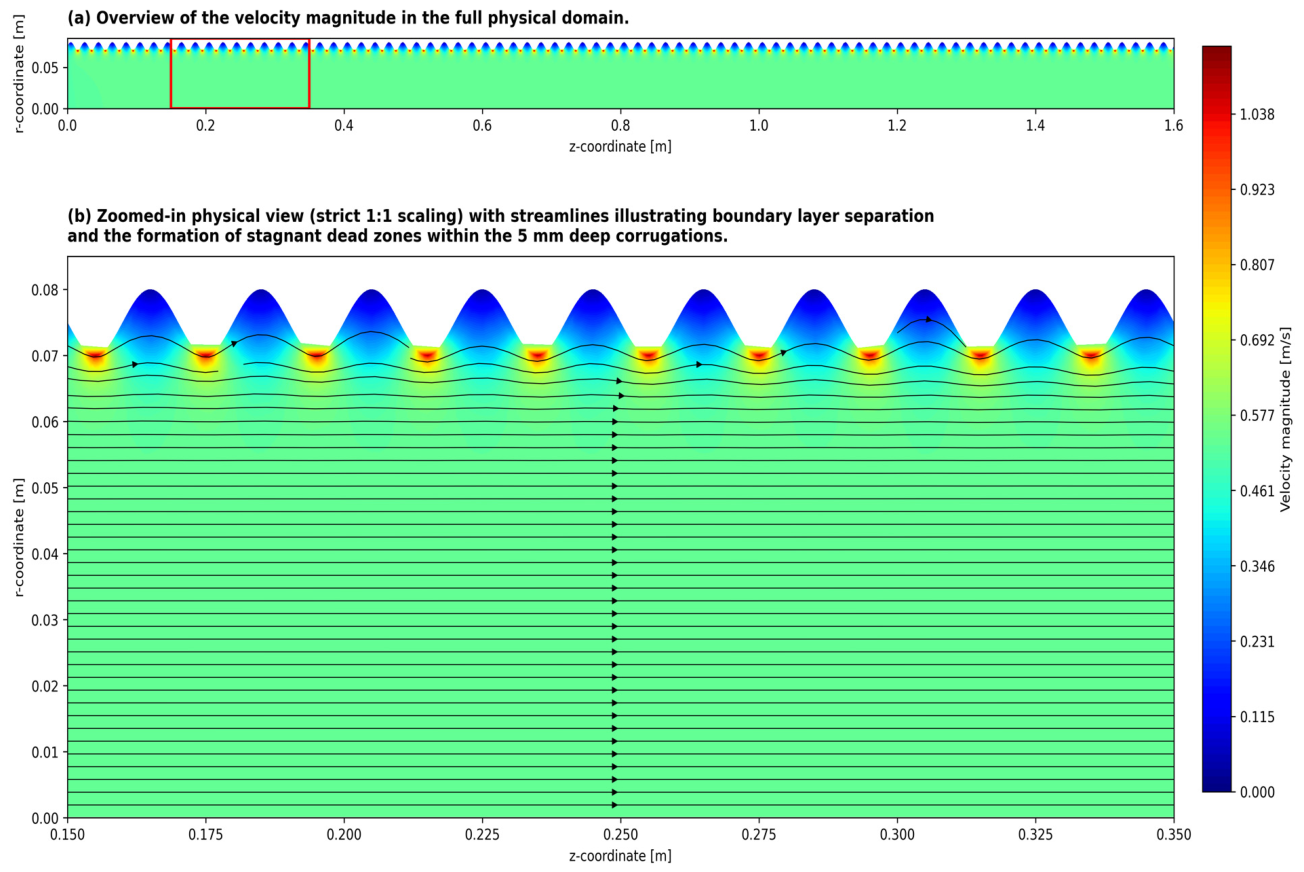
The results from the computational fluid dynamics model demonstrate the critical function of the macroscopic corrugations in managing exhaust flow. As illustrated in Figure 1, the primary exhaust gas rapidly accelerates and establishes a fully developed turbulent profile along the central axis of the 1600 mm duct, reaching peak core velocities of up to ~1.14 m/s. However, the true physical synergy of this geometry is revealed in the localized flow patterns near the grounded wall.
As clearly seen in the zoomed-in physical domain (Figure 1), the corrugation troughs act as highly efficient aerodynamic “dead zones.” Governed by the Reynolds-Averaged Navier–Stokes (RANS) equations, the high-velocity flow traveling over the corrugated peaks experiences severe adverse pressure gradients. This inevitably triggers boundary layer separation at the leading edge of each corrugation. The separated shear layer forms a bridge across the 20 mm pitch, preventing the chaotic, high-velocity turbulent eddies from penetrating deep into the 5 mm troughs.
Inside these troughs, the local velocity drops to near zero compared to the central stream, forming completely stagnant fluid pockets. Quantitative spatial analysis of the fluid domain reveals that while the core flow races at over 1 m/s, the mean gas velocity inside the deep corrugations plunges to merely ~0.13 m/s—an order of magnitude reduction. Unlike classical ‘skimming flow’ over deep cavities where the main shear layer drives a captive recirculation vortex, the geometry here is characterized by a shallow length-to-depth ( L / D ) ratio of 4 (20 mm pitch, 5 mm depth) and a relatively low Reynolds number in the duct. At these scales, kinematic viscosity becomes the dominant force within the restricted cavity space. The viscous dissipation effectively dampens out the kinetic energy transferred from the shear layer before a macro-scale vortex can form, locking the fluid into a stagnant ‘dead-water’ region.
The absence of strong recirculation vortices within the corrugations is highly advantageous for particle trapping. This aerodynamic shielding is the foundational pillar of the proposed mechanism: once sub-micron particulate matter is forcefully injected into these dead zones by extreme Coulombic pulses, it becomes completely isolated from the primary turbulent shear stresses. Because there are no spinning vortices to impart centrifugal forces or re-entrain the particles, they remain theoretically trapped under idealized hydrodynamic conditions within the stagnant air cushion [46,47].

3.2. Transient Electric Field and Space Charge Dynamics

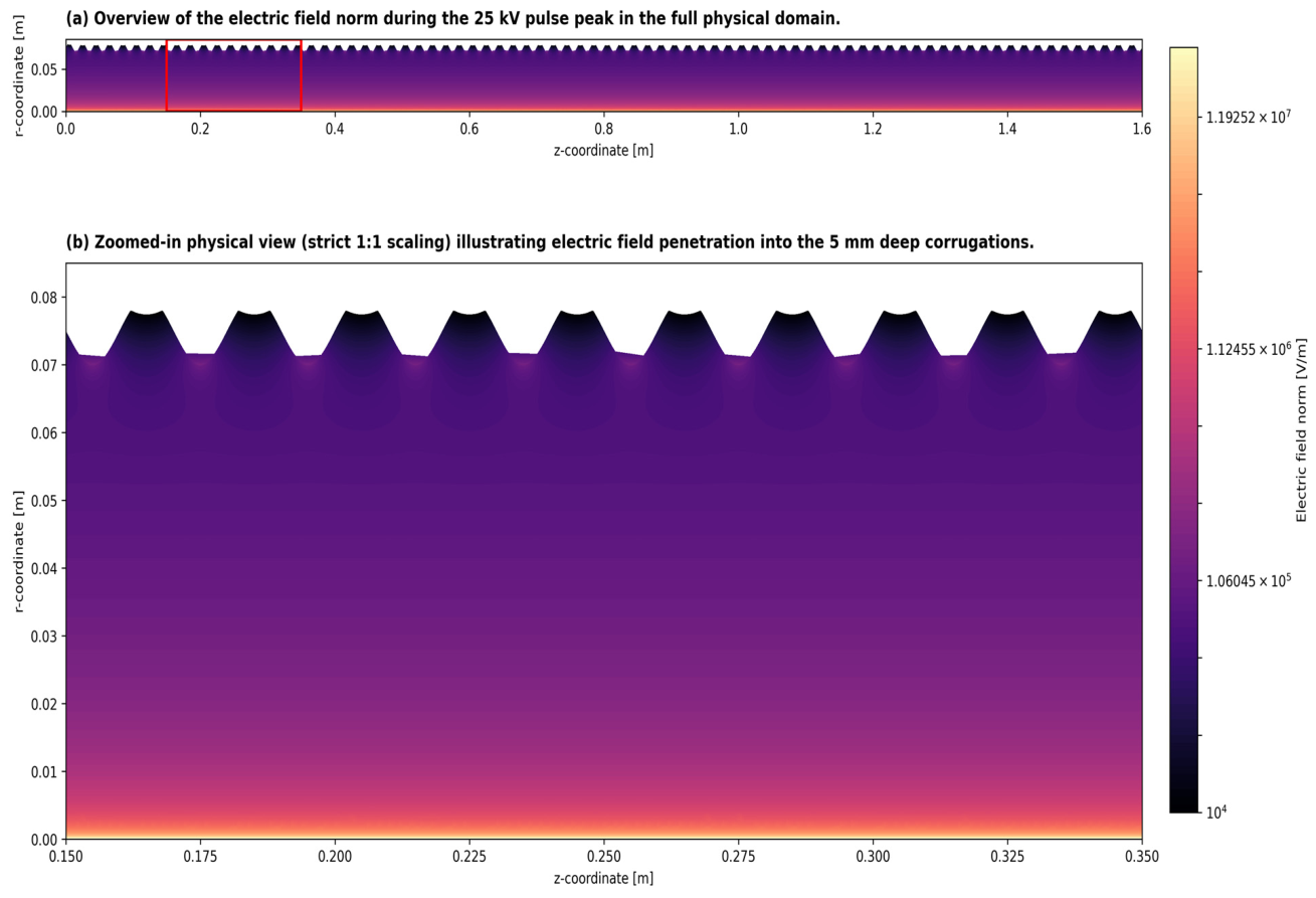
The implementation of a 1 kHz pulsed voltage strategy produced a highly transient electrohydrodynamic environment. The numerical solver successfully resolved the sharp voltage gradients, revealing that the space charge density and the resulting EHD body force propagate as discrete, high-intensity shockwaves radially outward from the corona wire during each active pulse. At the active corona wire, the electric field norm peaks at an extreme ~24.2 MV/m, providing the massive gradient necessary for robust ionization. Importantly, as the space charge expands, the electric field lines successfully penetrate deep into the 5 mm corrugation cavities, maintaining a localized driving force that averages ~10 kV/m. This guarantees sufficient electrostatic force to drive the final stage of kinetic injection into the deepest parts of the geometry (Figure 2).
Between pulses (the baseline phase), ionic injection ceases. The space charge cloud dissipates into the grounded wall, and the primary turbulent exhaust flow briefly regains total dominance over the domain. This intermittent actuation fundamentally alters the ionization profile, generating peak instantaneous forces that exceed those of a continuous DC system, while simultaneously keeping the time-averaged current exceptionally low.

3.3. Particle Trapping Kinetics

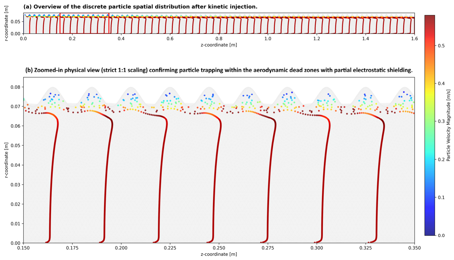
The trajectories of the 0.2 µm soot particles demonstrated a profound physical response to the pulsed EHD actuation. Visualizations of the discrete particle phase (Figure 3) showed an extensive clearing of particles from the central flow region. The intense Coulombic forces generated during the 25 kV peaks successfully overcame the turbulent drag, rapidly accelerating the particles toward the grounded wall. To highlight the trapping mechanism, the discrete particles are colored by their absolute velocity magnitude. As clearly visible in the zoomed-in physical view, particles entrained in the central stream exhibit high turbulent velocities (averaging ~0.55 m/s and peaking up to ~0.74 m/s, indicated by red/yellow), while those successfully pushed into the corrugation troughs display drastically reduced velocities (averaging just ~0.10 m/s, indicated by dark blue). This massive ~82% reduction in mean particle kinetic velocity provides direct, quantitative proof that the trapped particles have achieved aerodynamic stagnation within the aerodynamic dead zones, effectively significantly mitigating the theoretical risk of turbulent re-entrainment.
A quantitative analysis of the localized trapping efficiency revealed a characteristic “staircase” profile. Each vertical step in the trapping curve directly corresponded to an active voltage pulse, during which a discrete batch of particles was forcefully injected into the corrugation (the “kinetic injection” phase). Crucially, during the subsequent resting baseline phase, the trapped particle count remained perfectly flat. This horizontal plateau indicates that, within the simplified boundary assumptions of this model, particles remained localized, demonstrating how the corrugations act as aerodynamic dead zones with partial electrostatic shielding.

3.4. Parametric Analysis: Pulse Frequency and Duty Cycle

To thoroughly evaluate the physical limitations and optimize the energy efficiency of the transient trap, a parametric analysis was conducted by varying the pulse frequency ( f p u l s e ) and duty cycle ( D c y c l e ). The inlet flow velocity was maintained at 0.5 m/s, and the peak voltage was held constant at 25 kV. To decouple the effects of pulse duration from frequency, the absolute active pulse width was kept strictly constant at 0.1 ms across all tested cases. The system was evaluated at three distinct operating points: 500 Hz (5% duty cycle), 1 kHz (10% duty cycle), and 2 kHz (20% duty cycle).
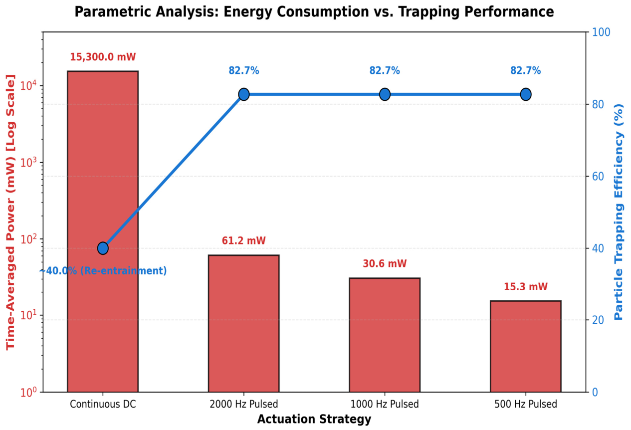
The computational results (summarized in Table 1 and visualized in Figure 4) revealed a profound and counter-intuitive physical phenomenon: the particle trapping efficiency remained exactly constant at a robust 82.7% across all three configurations. * At 500 Hz (5% duty cycle), the system drew an astonishingly low time-averaged active power of just 15.3 mW. The 0.1 ms active pulse provided sufficient intense EHD momentum (“kinetic injection”) to push the boundary-layer soot particles into the corrugations. During the long 1.9 ms resting phase, the aerodynamic shielding effectively minimized simulated re-entrainment. * At 1 kHz (10% duty cycle) and 2 kHz (20% duty cycle), the frequency of the pulse injections increased, and the time-averaged power consumption scaled proportionally (doubling and quadrupling, respectively). However, this additional power input yielded zero additional particle trapping benefit. The efficiency plateaued at exactly 82.7%.
This plateau indicates a fundamental kinetic limit: once the optimal pulse width (0.1 ms) establishes the required space charge shockwave to sweep the local volume, firing pulses more frequently only wastes electrical energy on an already cleared domain. Thus, the ultra-low frequency, low-duty configuration (500 Hz, 5%) is the absolute thermodynamic optimum for this geometry.

3.5. Comparison with Continuous DC Systems

When compared against standard reference data for continuous DC electrostatic precipitators, the proposed pulsed geometry offers distinct operational advantages (Table 1). Conventional DC ESPs require a continuous, high-voltage draw to maintain particle collection, which often suffers from power-draining back corona and severe re-entrainment in highly turbulent exhaust streams [48,49]. For a comparable 25 kV continuous DC corona discharge drawing approximately 1 mA of current, the power consumption is 15.3 W [46].
By shifting to the optimal 500 Hz, 5% duty cycle pulsed strategy, active corona power is drawn for only 5% of the operating cycle. As detailed in Table 1 and illustrated in Figure 4, this results in an theoretical comparison in time-averaged power consumption down to just 15.3 mW—a theoretical baseline for the required active plasma volume compared to traditional continuous DC ionization. Furthermore, the aerodynamically shielded corrugations demonstrate spatial segregation of particles that plague smooth-bore DC precipitators in turbulent environments [49].

4. Discussion

The successful integration of a macroscopic corrugated geometry with pulsed actuation highlights a highly synergistic collection mechanism. Under continuous DC voltage, particles are subjected to a constant force, often leading to rapid deposition but also significant re-entrainment due to continuous flow disruption at the wall, while wasting immense amounts of electrical energy.
In contrast, our proposed strategy explicitly decouples the collection force from the retention mechanism. It relies on “kinetic injection”—utilizing the short duration, high-intensity pulsed EHD forces to violently push particles out of the main flow and into the corrugation troughs. The parametric analysis decisively proves that once a critical pulse width (0.1 ms) is achieved, firing pulses more frequently (e.g., 2 kHz) provides no additional trapping benefit and only serves to increase power draw. Once inside the corrugations, the geometric shape provides dual shielding:
  • Partial Electrostatic Shielding: The conductive walls isolate the trapped particles from the external electric field fluctuations.
  • Aerodynamic Shielding: The troughs isolate the particles from the turbulent shear stresses of the primary gas flow.
This physical decoupling is critical for heavy-duty exhaust applications. Tuning the pulse frequency down to 500 Hz allows the system to operate at maximum kinetic efficiency (82.7%) while drawing only a fraction of a Watt.
It is important to acknowledge that the current numerical model represents an idealized proof-of-concept. In real-world exhaust conditions, secondary physical mechanisms such as thermophoresis, Brownian diffusion, particle agglomeration, wall roughness, soot rebound/resuspension, humidity variations, and engine-induced vibrations will undoubtedly influence the trapping efficiency. The ‘staircase’ trapping profile observed in this study serves as a theoretical baseline for the aerodynamic shielding mechanism, whereas empirical validation will be required to quantify the impact of these complex boundary interactions.
Furthermore, the calculated 15.3 mW power consumption represents the ideal active corona power delivered to the fluid volume. In a practical, full-scale 3D marine exhaust duct, the actual ‘wall-plug’ energy draw will be significantly higher. A matched-performance baseline must account for pulse generator inefficiencies, capacitive charging and discharging of the electrode-duct system, parasitic losses, space-charge-limited currents, and increased exhaust conductivity at elevated temperatures (e.g., 300 °C). Thus, the 99.9% reduction highlights a theoretical upper bound for the active plasma volume, guiding future empirical pulse-forming network (PFN) designs.

5. Conclusions

This study successfully developed a fully coupled, time-dependent multiphysics model to analyze transient EHD particle trapping in a corrugated duct. By integrating turbulent flow, space charge transport, and discrete particle kinetics with strict event-driven circuit coupling, the true physical mechanisms governing pulsed particle collection were elucidated. The key findings are as follows:
  • Discrete Kinetic Trapping: The results demonstrate that 0.2 µm sub-micron particulate matter can be efficiently collected in discrete, step-wise batches corresponding exactly to the active high-voltage pulses.
  • Aerodynamic Shielding: The macroscopic corrugated geometry (5 mm depth, 20 mm pitch) proved essential for long-term particle retention. The corrugation troughs act as aerodynamic aerodynamic dead zones with partial electrostatic shielding that isolate trapped particles from primary turbulent shear stresses, demonstrating localized advection during the low-voltage resting phases.
  • Optimal Pulsing Strategy: A parametric analysis revealed that maintaining a constant pulse width of 0.1 ms while varying the frequency (500 Hz to 2 kHz) resulted in a flat trapping efficiency of 82.7%. Increasing frequency beyond the critical minimum provided no additional trapping benefit.
  • Theoretical Active Power: Consequently, the lowest frequency tested—500 Hz with a 5% duty cycle—emerged as the absolute optimum. This transient strategy offers a highly optimized solution for active PM emission control, requiring an idealized active corona power of only 15.3 mW for the simulated fluid volume, serving strictly as a fundamental mathematical baseline without claims of system-level energy advantage.

Author Contributions

Conceptualization, A.Š. and J.M.; methodology, A.Š.; software, A.Š.; validation, A.Š., J.M. and P.J.; formal analysis, A.Š. and P.J.; writing—original draft preparation, A.Š.; writing—review and editing, J.M. and P.J. All authors have read and agreed to the published version of the manuscript.

Funding

This research received no external funding.

Institutional Review Board Statement

Not Applicable.

Informed Consent Statement

Not Applicable.

Data Availability Statement

The original data presented in this study are included in the article. Further inquiries can be directed to the corresponding author.

Conflicts of Interest

The authors declare no conflicts of interest.

Nomenclature

SymbolDescriptionUnit
D c y c l e Pulse duty cycle %
D e Ion diffusion coefficient m 2 / s
E Electric field vectorV/m
f p u l s e Pulse frequencyHz
F D Aerodynamic drag forceN
F E H D Electrohydrodynamic body force N / m 3
F E Coulombic electrostatic forceN
k Turbulent kinetic energy m 2 / s 2
L Total length of the exhaust ductmm
L / D Corrugation length-to-depth ratio-
m p Particle masskg
p Fluid pressurePa
q p Particle chargeC
r Radial coordinatem
r w Radius of the corona wiremm
R i n Inner radius of the exhaust ductmm
U Mean gas velocity vectorm/s
V Electric potentialV
V 0 Peak voltage of the pulse sourcekV
v p Particle velocity vectorm/s
z Axial coordinatem
εTurbulent dissipation rate m 2 / s 3
ϵ 0 Vacuum permittivityF/m
ϵ r Relative permittivity-
μ Dynamic viscosity P a s
μ e Ion mobility m 2 / V s
μ t Turbulent eddy viscosity P a s
ρ Fluid density k g / m 3
ρ q Space charge density C / m 3

References

  1. Čeponis, A.; Matijošius, J.; Šišovas, L.; Kilikevičius, A. Investigation of air-coupled ultrasonic transmitter–receiver sensor with single matching layer made of common polymer-based plastics. Appl. Acoust. 2025, 243, 111140. [Google Scholar]
  2. Vračar, L.; Milovančević, M.; Vračar, J.; Matijošius, J.; Kilikevičius, A.; Buchmeister, B. Mqtt enabled device for industrial environment and smart city. Facta Univ. Ser. Mech. Eng. 2026, 24, 171. [Google Scholar] [CrossRef] [Scilit]
  3. Aprepary, P.A.; Halim, B.A.; Khoshbakhtnejad, E.; Amili, O.; Sojoudi, H. Understanding Electrohydrodynamic Flow Using Particle Image Velocimetry in Alternating Current Corona Discharge Systems. J. Fluids Eng. 2025, 148, 021201. [Google Scholar] [CrossRef] [Scilit]
  4. Koszyk, J.; Hyla, B.; Pieczonka, L.J.; Łukasz, A. Multi-sensor robotic mapping with thermal and acoustic imaging for non-contact technical diagnostics. Eksploat. Niezawodn.-Maint. Reliab. 2026, 28, 217575. [Google Scholar]
  5. Li, G.; Xu, T.; Ding, S. A Data-Driven Complex Network Approach for Aviation Piston Engine Safety: Critical Causation Analysis and Predictive Intervention. Eksploat. Niezawodn.-Maint. Reliab. 2026, 28, 218331. [Google Scholar] [CrossRef] [Scilit]
  6. Wang, Y.; Yuan, Z.; Chen, Y.; Li, M.; Bai, X.; Liu, X. Streamer-like pulses initiated by oxide breakdown: Mechanism and mode transition in negative silicon needle corona discharge. J. Phys. D Appl. Phys. 2026, 59, 205206. [Google Scholar] [CrossRef] [Scilit]
  7. Caban, J.; Šarkan, B.; Małek, A.; Dowkontt, S.; Loman, M. Data-Driven Analysis of Electric Powertrain Energy Flow and Traction Battery Behavior in a Modern Battery Electric Vehicle Using Real-World OBD Data. Electronics 2026, 15, 2018. [Google Scholar] [CrossRef] [Scilit]
  8. Kozłowski, E.; Traczyński, M.; Skoczyński, P.; Jaskowski, P.; Madleňák, R. Risk Factor Analysis of Single Motorcycle Accidents in Road Traffic. Appl. Sci. 2026, 16, 1629. [Google Scholar] [CrossRef] [Scilit]
  9. Fu, H.; Meng, S.; Luo, X.; Zheng, Q.; Li, S.; Liu, Z.; Yan, K. Investigation on heat exchange assisted wet electrostatic precipitator in dust removal, heat transfer enhancement process and water collection. J. Electrost. 2026, 140, 104231. [Google Scholar] [CrossRef] [Scilit]
  10. Šabanovič, A.; Matijošius, J. Optimization of Ionic Wind Filtration Systems for Atmospheric Particulate Matter Removal: A Hybrid Numerical and Empirical Modeling Approach. Atmosphere 2026, 17, 435. [Google Scholar] [CrossRef] [Scilit]
  11. Masrouri, M.; Yagoobi, J. Fundamental understanding of flow distribution control in parallel multi-channel heat transfer devices with electrohydrodynamic conduction pumping. Int. J. Heat Mass Transf. 2026, 260, 128445. [Google Scholar] [CrossRef] [Scilit]
  12. Piščalov, A.; Rafanavičius, V.; Kilikevičius, A.; Čeponis, A. Kinematic Analysis and Simulation of Workspace of a 6-DOF Positioning Platform. Mathematics 2026, 14, 1344. [Google Scholar] [CrossRef] [Scilit]
  13. Balthy, M.K.; Raman, R.; Lather, R.S.; Çalışkan, H.; Barmavatu, P.; Hong, H.; Kale, U.; Kilikevičius, A. A novel end-of-line acoustic–vibration-based testing tool for quality assurance and supplier control of gasoline direct injection fuel pump. Flow Meas. Instrum. 2026, 110, 103338. [Google Scholar] [CrossRef] [Scilit]
  14. Jaśkowskí, P.; Kozłowski, E.; Tomczuk, P.; Chrzanowicz, M.; Matijošius, J.; Cholewa-Wiktor, M.; Kilikevičius, A. Application of machine learning models for evaluating the impact of roadside advertising on driver discomfort. Measurement 2025, 255, 117915. [Google Scholar] [CrossRef] [Scilit]
  15. Miłek, T.; Orynycz, O.; Matijošius, J.; Tucki, K.; Kulesza, E.; Kozłowski, E.; Wasiak, A. Research on Energy Management in Forward Extrusion Processes Based on Experiment and Finite Element Method Application. Materials 2025, 18, 2616. [Google Scholar] [CrossRef] [Scilit] [PubMed]
  16. Matar, I.; Daaboul, M.; Louste, C. Effect of polarity change on asymmetric cylinder-to-cylinder EHD device. J. Electrost. 2026, 141, 104276. [Google Scholar] [CrossRef] [Scilit]
  17. Zhao, H.; Li, P.; Liu, H.; Liu, T.; Yang, Z. Understanding and Mitigating Corona Quenching in ESPs Under High Fly Ash Concentrations in a 660 MW Coal-Fired Unit. Separations 2026, 13, 60. [Google Scholar] [CrossRef] [Scilit]
  18. Li, X.X.; Geng, Q.; Wang, C.; Wang, Y.; Yin, Y.; Ren, H.; Wáng, Y.; Li, Q. Evolution mechanism and phase-field modeling of crack defects leading to discharge brittle fracture in GIL tri-post insulator. IEEE Trans. Dielectr. Electr. Insul. 2026. [Google Scholar]
  19. Zhang, S.; Liu, J.; Li, A.; Wang, J.; Wu, L.; Gu, S.; Yang, X. Qualitative verification of the scattering enhancement effect by surface charge on submicron particles. Opt. Laser Technol. 2025, 195, 114615. [Google Scholar] [CrossRef] [Scilit]
  20. Wymenga, L.F.A.; Turnhout, J.v.; Niasar, M.G.; Zeijl, H.v.; Driel, W.D.v.; Zhang, G.Q. Design Considerations for Low-Temperature Plasma Production in Air Using Pulsed Dielectric Barrier Discharges: A Review. Plasma 2026, 9, 15. [Google Scholar] [CrossRef] [Scilit]
  21. Nejad, J.V.N.; Kheradmand, S.; AtaAbadi, P.K. Comprehensive study of cyclone separator performance under non-uniform flow: Correlation proposal. Particuology 2026, 111, 105–119. [Google Scholar] [CrossRef] [Scilit]
  22. Lee, Y.; Son, J.; Chang, H.; Yook, S. Comparative study on soot particle resuspension from coniferous and broadleaf urban tree species. Aerosol Sci. Technol. 2026, 1–15. [Google Scholar] [CrossRef] [Scilit]
  23. Laskowski, P.; Kozłowski, E.; Zimakowska-Laskowska, M.; Wiśniowski, P.; Matijosius, J.; Oszczak, S.; Keršys, R.; Wojs, M.K.; Dowkontt, S. Dynamic CO2 Emission Differences Between E10 and E85 Fuels Based on Speed–Acceleration Mapping. Energies 2025, 19, 40. [Google Scholar] [CrossRef] [Scilit]
  24. Wang, Z.; Burton, J.C.; Dormagen, N.; Du, C.-R.; Feng, Y.; Foster, J.E.; Glenn, S.S.; Klein, M.; Knapek, C.A.; Matthews, L.; et al. DustNET: Enabling machine learning and AI models of dusty plasmas. arXiv 2026, arXiv:2603.17493. [Google Scholar]
  25. Wu, J.; Yang, P.; Sun, D.; Huang, Y.; Yang, Z. Experimental study on flow characteristics of electrohydrodynamic plumes in a needle-plate configuration with viscoelastic dielectric liquids. Exp. Fluids 2026, 67, 63. [Google Scholar] [CrossRef] [Scilit]
  26. Poeppe, D.; Ungerer, M.; Kriegseis, J.; Hehner, M.T.; Sieber, I. Particle image velocimetry for spray measurement of an Aerosol-on-Demand jet-printhead. J. Aerosol Sci. 2026, 193, 106760. [Google Scholar] [CrossRef] [Scilit]
  27. Batool, S.S.; Batool, S.M.; DeSutter, T.M.; Meehan, M.A.; Oduor, P.G. Smart Bioaerosol Monitoring: Advanced Sampling and Sensing across Environmental, Clinical, and Industrial Domains. ACS Omega 2026, 11, 4868–4902. [Google Scholar] [CrossRef] [Scilit] [PubMed]
  28. Sokolovskij, E.; Kilikevičius, A.; Chlebnikovas, A.; Matijošius, J.; Vainorius, D. Innovative Electrostatic Precipitator Solutions for Efficient Removal of Fine Particulate Matter: Enhancing Performance and Energy Efficiency. Machines 2024, 12, 761. [Google Scholar] [CrossRef] [Scilit]
  29. Kilikevičius, A.; Chlebnikovas, A.; Kilikevičienė, K.; Kačeniauskas, A.; Stupak, E.; Pacevič, R.; Vainorius, D. Studies on the reduction of dispersed emissions from a low-power household boiler in a plasma ionic wind zone. J. Electrost. 2024, 130, 103951. [Google Scholar] [CrossRef] [Scilit]
  30. Fylladitakis, E.D.; Theodoridis, M.P.; Moronis, A.X. Review on the history, research, and applications of electrohydrodynamics. IEEE Trans. Plasma Sci. 2014, 42, 358–375. [Google Scholar] [CrossRef] [Scilit]
  31. Iranshahi, K.; Defraeye, T.; Rossi, R.M.; Müller, U.C. Electrohydrodynamics and its applications: Recent advances and future perspectives. Int. J. Heat Mass Transf. 2024, 219, 124856. [Google Scholar]
  32. Ramos, A. Electrohydrodynamic pumping in microsystems. J. Phys. Conf. Ser. 2011, 301, 012028. [Google Scholar] [CrossRef] [Scilit]
  33. Mizeraczyk, J.; Berendt, A.; Podliński, J.; Niewulis, A. Evolution of electrohydrodynamic flow of suspended particles in a needle-to-plate negative DC corona discharge in air. Int. J. Plasma Environ. Sci. Technol. 2016, 10, 58–63. [Google Scholar]
  34. Vaddi, R.S.; Guan, Y.; Novosselov, I. Behavior of ultrafine particles in electro-hydrodynamic flow induced by corona discharge. J. Aerosol Sci. 2020, 142, 105503. [Google Scholar]
  35. Okubo, M. Development of super-clean diesel engine and combustor using nonthermal plasma hybrid aftertreatment. J. Phys. Conf. Ser. 2015, 646, 012051. [Google Scholar] [CrossRef] [Scilit]
  36. Vinogradov, J.; Rivin, B.; Sher, E. NOx reduction from compression ignition engines with pulsed corona discharge. Energy 2008, 33, 1238–1247. [Google Scholar] [CrossRef] [Scilit]
  37. Baksht, R.B.; Yankelevich, Y.; Pokryvailo, A.; Oreshkin, V.I. Pulse repetition rate effect on nanosecond pulse corona discharge. IEEE Trans. Plasma Sci. 2006, 34, 1686–1691. [Google Scholar] [CrossRef] [Scilit]
  38. Weng, L.; Shi, X.; Ye, Q.; Liu, Y. The Application of Pulsed Corona Discharge Plasma Technology in Air Pollution Control. In Proceedings of the 16th Annual Conference of China Electrotechnical Society; Lecture Notes Electrical Engineering; Springer: Berlin/Heidelberg, Germany, 2022; Volume 865, pp. 233–242. [Google Scholar]
  39. Stishkov, Y.K.; Chirkov, V.A. Formation of electrohydrodynamic flows in strongly nonuniform electric fields for two charge-formation modes. Tech. Phys. 2012, 57, 466–472. [Google Scholar] [CrossRef] [Scilit]
  40. Chirkov, V.A.; Stishkov, Y.K.; Sitnikov, A.A. Simulation of the integral electric current characteristics of unsteady-state current passage through liquid dielectrics. IEEE Trans. Dielectr. Electr. Insul. 2015, 22, 2454–2462. [Google Scholar] [CrossRef] [Scilit]
  41. Zhang, Y.; Wu, Z.; Xin, L.; Peng, Z. Study on Capture Efficiency of Particle Trap and Performance Improvement Method for DC GIL/GIS. IEEE Trans. Dielectr. Electr. Insul. 2023, 30, 1789–1797. [Google Scholar] [CrossRef] [Scilit]
  42. Yu, X.; Huang, D.; Wang, Y. Study on the Impact of Particle Trap Structural Parameters on Electric Field Distribution in 500kV GIL. J. Phys. Conf. Ser. 2025, 3012, 012049. [Google Scholar] [CrossRef] [Scilit]
  43. Chapman, S.J.; Hewett, D.P.; Trefethen, L.N. Mathematics of the faraday cage. SIAM Rev. 2015, 57, 398–417. [Google Scholar] [CrossRef] [Scilit]
  44. Hansen, T. Modeling and Experimental Analysis of Wet Electrostatic Precipitator for Reduction of Particulate Matter from Marine Engines. Ph.D. Thesis, Aalborg University, Aalborg, Denmark, 2023. [Google Scholar] [CrossRef] [Scilit]
  45. Kuittinen, N.; MarjanenJussi, P.; Hoivala, J.; MäkinenAnssi, U.-V.; Järvinen, A.; Lehtoranta, K.; Aakko-Saksa, P.; Orasuo, V.; Jokiluoma, J.; Rönkkö, T.; et al. Effect of Scrubber and Wet Electrostatic Precipitator on Secondary Aerosol Formation Potential of Marine Engine Exhaust. ACS EST Air 2026, 3, 662–669. [Google Scholar] [CrossRef]
  46. Perry, A.E.; Schofield, W.H.; Joubert, P.N. Rough wall turbulent boundary layers. J. Fluid Mech. 1969, 37, 383–413. [Google Scholar] [CrossRef] [Scilit]
  47. Chang, P.S.; Scott, D.D. Turbulent flow over corrugated surfaces. Int. J. Heat Fluid Flow 2004, 25, 200–212. [Google Scholar]
  48. Mizuno, A. Electrostatic precipitation. IEEE Trans. Dielectr. Electr. Insul. 2000, 7, 615–624. [Google Scholar] [CrossRef] [Scilit]
  49. Jaworek, A.; Machowski, W.; Krupa, A. Micro- and nanoparticle charging and collection in electrostatic precipitators. J. Electrost. 2007, 65, 133–140. [Google Scholar] [CrossRef] [Scilit]
Figure 1. (a) Overview of the velocity magnitude in the full physical domain. (b) Zoomed-in (red box) physical view (strict 1:1 scaling) with streamlines illustrating boundary layer separation and the formation of stagnant dead zones within the 5 mm deep corrugations.
Actuators 15 00405 g001
Figure 2. (a) Overview of the electric field norm during the 25 kV pulse peak in the full physical domain. (b) Zoomed-in physical view (strict 1:1 scaling) illustrating electric field penetration into the 5 mm deep corrugations.
Actuators 15 00405 g002
Figure 3. (a) Overview of the discrete particle spatial distribution after kinetic injection. Particles are colored by velocity magnitude. (b) Zoomed-in physical view (strict 1:1 scaling) near the inlet (z = 0.15 m) confirming absolute particle stagnation (dark blue) within the aerodynamic dead zones with partial electrostatic shielding.
Actuators 15 00405 g003
Figure 4. Parametric analysis comparing energy consumption (log scale) against particle trapping performance. The data decisively illustrate that increasing the pulse frequency beyond 500 Hz provides no additional trapping benefit while scaling the power draw linearly.
Actuators 15 00405 g004
Table 1. Parametric Comparison of Actuation Strategies.
Actuation StrategyFrequency (Hz)Duty Cycle (%)Trapping Efficiency (%)Time-Averaged Power (mW)
Continuous DC0 (DC)100%~40.0% (Re-entrainment)~15,300.0
Pulsed EHD200020%82.7%61.2
Pulsed EHD100010%82.7%30.6
Pulsed EHD (Optimum)5005%82.7%15.3
Disclaimer/Publisher’s Note: The statements, opinions and data contained in all publications are solely those of the individual author(s) and contributor(s) and not of MDPI and/or the editor(s). MDPI and/or the editor(s) disclaim responsibility for any injury to people or property resulting from any ideas, methods, instructions or products referred to in the content.