Article

A Multi-Agent Synchronization Control-Based Method for Determining Center-of-Mass Coordinates in Engineering Vehicles with Active Suspension

1
School of Mechanical Engineering, Yanshan University, Qinhuangdao 066004, China
2
State Key Laboratory of Crane Technology, Yanshan University, Qinhuangdao 066004, China
3
Tai’an Aerospace Special Vehicle Co., Ltd., Tai’an 271000, China
*
Author to whom correspondence should be addressed.
Actuators 2026, 15(7), 406; https://doi.org/10.3390/act15070406
Submission received: 10 June 2026 / Revised: 29 June 2026 / Accepted: 3 July 2026 / Published: 21 July 2026
(This article belongs to the Section Actuators for Surface Vehicles)

Abstract

The center-of-mass (CoM) coordinates of engineering vehicles vary with payload mass, payload position, and upper-structure posture, whereas active suspension control systems commonly use fixed CoM parameters. To enable convenient CoM updating under different stable operating conditions, this study proposes a multi-agent synchronization control-based method for determining CoM coordinates in engineering vehicles equipped with active suspension. Each active suspension actuator is modeled as an agent, and a four-actuator multi-agent system with a distributed consensus controller is developed to improve displacement synchronization and reduce the influence of actuator asynchrony on vertical support-force identification. A CoM coordinate determination model is then established using the mass reaction method and mass-weighted averaging, so that the vehicle CoM can be recalculated after the vehicle enters a new stable operating condition. Simulations and full-vehicle experiments were conducted on a two-axle crane equipped with active suspension at boom posture angles of 0°, 10°, and 20°. Compared with test-bench reference measurements, the maximum coordinate errors were 10.51 mm, 4.85 mm, and 92.45 mm, respectively. The results indicate that the proposed method can provide CoM coordinates consistent with reference values under stable operating conditions and support control-parameter updating after changes in payload state or upper-structure posture.

1. Introduction

The center-of-mass (CoM) coordinates of heavy engineering vehicles are key parameters that affect handling performance and active control. In some heavy engineering vehicles, payload position and operating posture can change the CoM distribution; therefore, the vehicle CoM is not always a fixed structural parameter but may shift with the operating condition. Accurate CoM coordinates are an important prerequisite for load distribution, posture regulation, and stability control in active suspension systems, because the CoM position directly affects the vertical support-force distribution among actuators and the calculation of posture-regulation moments. Therefore, for engineering vehicles equipped with active suspension, a key issue is how to conveniently obtain updated CoM coordinates under a new stable operating condition by using the onboard active-suspension system itself, including actuator displacement regulation and support-force information, rather than relying on repeated test-bench CoM measurements after each operating-condition change [1,2,3].
At present, vehicle CoM measurement still relies mainly on test-bench experiments, such as four-wheel weighing, tilt-platform methods, and static measurement methods based on force and moment equilibrium [4,5,6]. Previous studies have improved the reliability of static measurement results by increasing weighing accuracy, refining measurement procedures, and compensating for measurement errors [7]. However, these methods usually depend on fixed operating conditions. Once the vehicle structural posture changes, for example, because of a change in payload position or the posture of the upper structure of a heavy engineering vehicle, test-bench measurements must be repeated. This leads to high testing costs and low efficiency, making it difficult to meet the demand for rapid multi-condition evaluation. To address this issue, recent studies have increasingly focused on dynamic estimation methods based on dynamic models and sensor fusion. For example, CoM estimation methods based on the extended Kalman filter (EKF) and unscented Kalman filter (UKF) have been widely applied to vehicle parameter identification and state estimation [8,9,10,11,12,13]. Multi-sensor fusion techniques, such as IMU and GPS integration, have also been used to improve estimation accuracy and robustness [14,15,16,17]. In addition, machine-learning methods have been introduced to develop data-driven models for CoM prediction under complex operating conditions [18,19,20]. Although these methods have advantages under dynamic conditions, they generally require strong system excitation and high-precision sensor configurations. Under low-speed or quasi-static conditions, their estimation accuracy and engineering applicability remain limited.
On the other hand, in methods that determine the CoM from the vertical support forces of actuators, the measurement accuracy depends not only on the accuracy of the mechanical model but also on the consistency of actuator motion. Previous studies have shown that, in multi-actuator hydraulic systems, synchronization errors among actuators are commonly associated with differences in hydraulic parameters, nonuniform load distribution, friction nonlinearities, and instability in valve-controlled actuation. For mobile engineering vehicles operating in field environments, external mechanical vibrations may also induce forced vibrations of the spool in proportional or servo valves, leading to pressure pulsations and actuator positioning deviations. These factors can degrade the consistency of multi-actuator displacement responses and further affect the accuracy of CoM coordinate determination based on vertical support forces [21,22,23,24,25,26]. To address multi-actuator coordination, several synchronization control methods have been proposed, including master–slave control, cross-coupling control, and error-compensation-based coordination strategies [27,28,29]. With the development of multi-agent system theory, consensus control has become an important topic in distributed cooperative control. Through local information exchange, multi-agent consensus control can achieve global coordination and has been widely investigated in consensus tracking, fault estimation and fault-tolerant control, time-varying formation control, and multi-actuator coordination problems [30,31,32,33,34,35]. For multi-actuator active suspension systems, this distributed coordination idea provides a theoretical basis for suppressing relative displacement errors among actuators. However, existing studies have mostly focused on either CoM measurement or consensus control separately. In the determination of CoM coordinates for heavy engineering vehicles, the influence of actuator synchronization has not been sufficiently considered. Moreover, for CoM variation under multi-posture operating conditions, existing methods still struggle to balance measurement convenience and engineering applicability.
To address these problems, this study focuses on determining the CoM coordinates of engineering vehicles with active suspension under different stable operating conditions. A multi-agent consensus-based actuator synchronization control method is proposed. Each active suspension actuator is modeled as an independent agent, and a distributed coordination strategy is developed to achieve synchronized motion among multiple actuators, thereby reducing the influence of actuator asynchrony on vertical support-force identification and CoM coordinate determination. On this basis, force equilibrium and the mass reaction method are combined to determine and analyze the vehicle CoM coordinates under stable operating conditions with boom posture angles of 0°, 10°, and 20°, enabling the CoM parameters to be updated under different stable conditions. Simulation and full-vehicle experimental results show that the proposed method can obtain vehicle CoM coordinates that are consistent with test-bench reference measurements, providing a feasible approach for updating CoM parameters in engineering vehicles with active suspension.
Compared with existing studies, the main contribution of this work is threefold. First, a stable-condition CoM coordinate determination method is developed by using the actuator displacement regulation and support-force information of the onboard active-suspension system, reducing the need for repeated test-bench CoM measurements after operating-condition changes. Second, multi-agent synchronization control is used to improve actuator displacement consistency and reduce the influence of actuator asynchrony on support-force identification and CoM calculation. Third, force equilibrium, the mass reaction method, and mass-weighted averaging are integrated to determine the CoM coordinates of both the sprung mass and the whole vehicle, and the feasibility of the method is verified through simulations and full-vehicle experiments under the investigated operating conditions.

2. Center-of-Mass Coordinate Determination Method

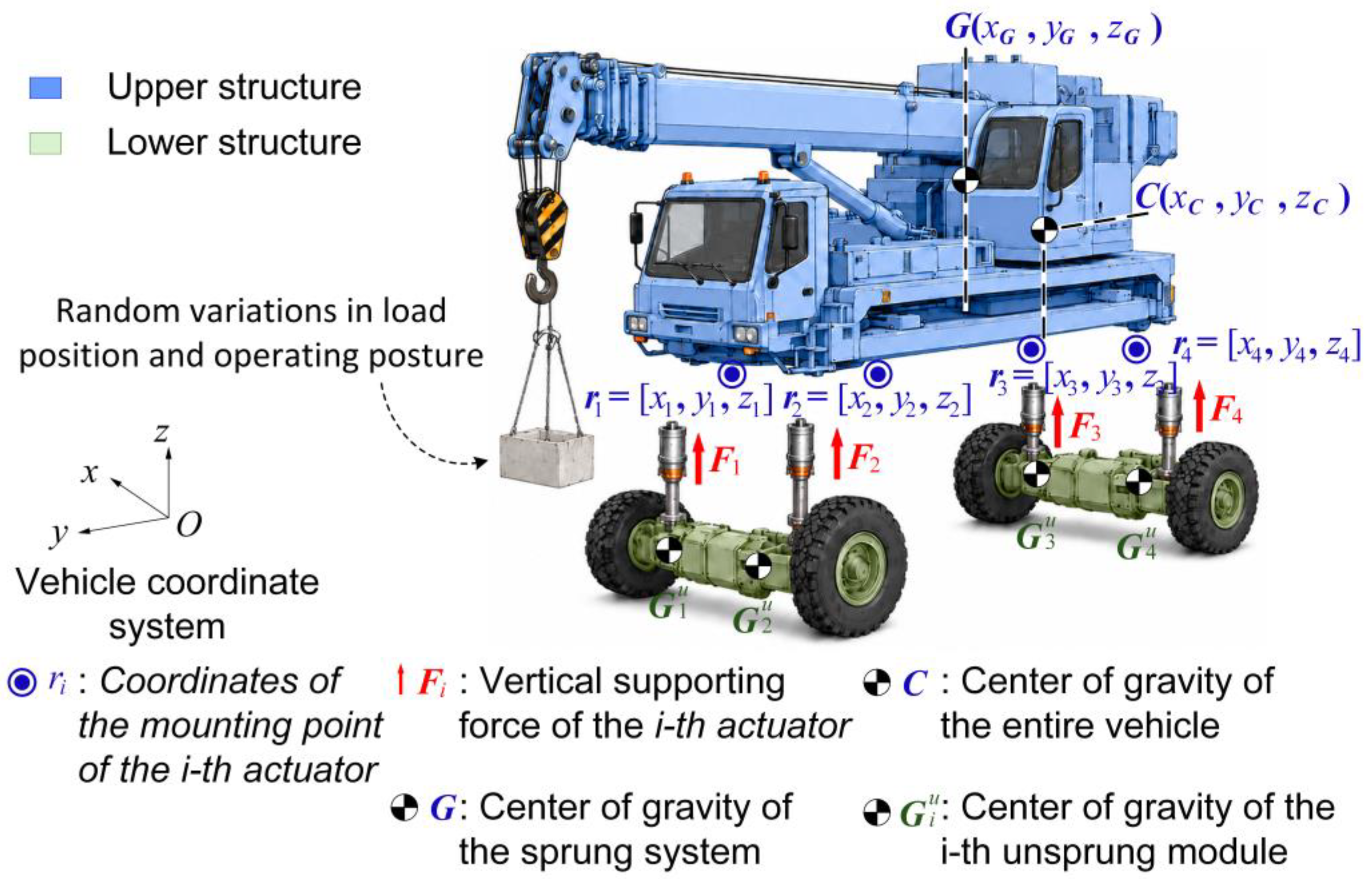
To rapidly determine the center-of-mass (CoM) coordinates of a heavy engineering vehicle equipped with active suspension, a simplified schematic model is established, as shown in Figure 1. The vehicle system consists of the unsprung mass, the main-body mass, and the boom mass, where the main-body mass and the boom mass together form the sprung mass. A vehicle coordinate system OXYZ is defined, in which the positive X-axis points to the right-hand side of the vehicle relative to the driving direction, the positive Y-axis points along the driving direction, and the positive Z-axis points vertically upward. The proposed method is mainly intended for quasi-static conditions after the vehicle has reached a stable support state. Under this condition, the actuator displacements, vehicle posture, and vertical support forces remain nearly stable within the selected data window, and thus static force and moment equilibrium relationships can be used for CoM coordinate calculation. For heavy engineering vehicles, changes in payload position and operating posture mainly affect the CoM coordinates of the sprung mass. Therefore, the unsprung mass and its CoM coordinates are treated as known fixed parameters in this study, and the CoM coordinates of the sprung mass are first determined. The sprung and unsprung masses are connected by actuators, which provide vertical support forces to the sprung mass. Considering that the experiments in this study are conducted under stable conditions and within a limited posture variation range, the effects of frame flexibility, suspension compliance, and tire deformation on the geometric relationship of the actuator mounting points and vertical support-force identification are neglected in the model.
The actuator vertical support-force vector and the mounting-position vector are defined as follows:
F = F 1 F 2 F 3 F 4 ,   r i = x i y i z i
where Fi denotes the vertical support force of the i-th actuator, and (xi, yi) denotes the horizontal coordinates of the connection point between the actuator and the sprung mass in the vehicle coordinate system. The mounting-position matrix is constructed as follows:
R = x 1 x 2 x 3 x 4 y 1 y 2 y 3 y 4
Under quasi-static conditions, the sprung mass satisfies vertical force equilibrium and moment equilibrium about the X- and Y-axes. The horizontal center-of-mass coordinates of the sprung mass can be expressed as:
r G , x y = x G y G = 1 ( M a + M b ) g R F
where Mb is the main-body mass, Ma is the boom mass, and g is the gravitational acceleration. This equation indicates that the horizontal center-of-mass coordinates of the sprung mass are jointly determined by the distribution of the actuator vertical support forces and the geometric positions of the actuators.
Since the horizontal moment equilibrium relationship does not contain information about the center-of-mass height, zG cannot be obtained directly. Therefore, the mass reaction method is introduced to determine the center-of-mass height by applying a small displacement perturbation and measuring the corresponding change in support force. Taking a small displacement perturbation applied to the right-side actuators as an example, the left-side actuator displacements are kept unchanged, while a vertical displacement increment ∆z is synchronously applied to the right-side actuators. The lateral distance between the left- and right-side actuators is defined as a , and the roll angle of the sprung mass is then given by γ = arctan(∆z/a). The left-side force aggregation operator is defined as:
e l = 0 1 0 1 T
Thus, the total support force on the left side can be expressed as:
F l = e l T F
After the perturbation is applied, the system reaches a new static equilibrium. The total support force on the left side becomes F′, and the height of the center of mass relative to the reference plane can be expressed as:
δ z = e l T ( F F ) a ( M a + M b ) g tan ( γ )
According to Equation (6), the height of the CoM relative to the reference plane is mainly determined by the difference in actuator support forces before and after posture adjustment and by the actuator mounting distance. Therefore, compared with the horizontal CoM coordinates, the vertical CoM coordinate is more sensitive to pressure measurement errors, pressure-to-force calibration errors, actuator displacement errors, posture stability, and hydraulic friction hysteresis. To reduce the influence of hydraulic friction and path-dependent hysteresis on support-force identification, the target position is approached from two directions in the experiment, and the steady-state support forces are averaged. The height of the reference plane is defined as the average z-coordinate of the actuator mounting points. Therefore, the vertical coordinate of the center of mass of the sprung mass is:
z G = z r e f + δ z
The center-of-mass coordinates of the sprung mass can be written as:
r G = x G y G z G T
The mass vector and center-of-mass coordinate matrix of the unsprung mass are defined as:
m u = m 1 u m 2 u m 3 u m 4 u ,   R u = x 1 u x 2 u x 3 u x 4 u y 1 u y 2 u y 3 u y 4 u z 1 u z 2 u z 3 u z 4 u
The center-of-mass coordinates of the whole vehicle can then be obtained by mass-weighted averaging:
r C = ( M a + M b ) r G + R u m u ( M a + M b ) + 1 T m u
When a small displacement perturbation is applied to the left-side actuators, the corresponding force aggregation operator can be defined in the same manner, and the procedure for determining the center-of-mass height remains consistent with that described above.

3. Multi-Agent-Based Synchronization Controller Design

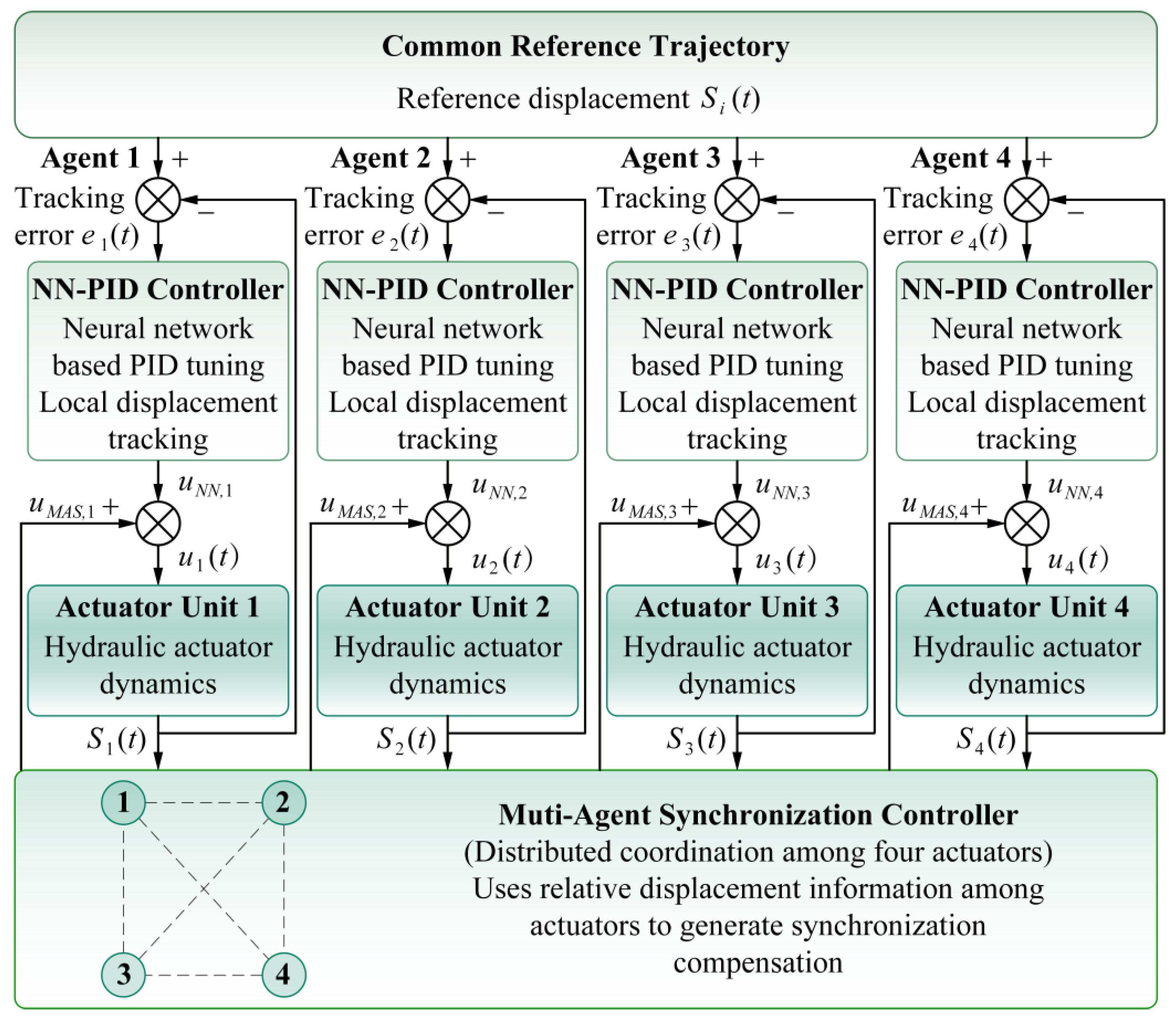
In the process of determining the center-of-mass coordinates of heavy engineering vehicles equipped with active suspension, the four hydraulic actuators are required to generate consistent displacement responses according to the determination strategy. This is necessary to avoid body posture distortion caused by asynchronous actuator motion, which may affect the accuracy of determining the center-of-mass coordinates of the sprung mass. In practical systems, even when the four actuators receive the same control signal, their dynamic responses may still differ significantly because of differences in load distribution, manufacturing errors, friction characteristics, hydraulic internal leakage, and pipeline damping. Therefore, it is necessary to introduce a synchronization compensation mechanism among the actuators on the basis of displacement tracking control for individual actuators. The structure of the composite controller is shown in Figure 2.
Let the actual displacement of the i -th actuator be s i ( t ) , and let the input control current be u i ( t ) . Near the rated operating point, the servo-valve–hydraulic-actuator–load system can be equivalently represented as a second-order dynamic system with inertia, damping, and hydraulic elasticity. This model retains the dominant dynamic characteristics from the control current to the actuator displacement output, while avoiding the introduction of excessive hydraulic nonlinear parameters that are difficult to identify accurately. Therefore, it is suitable as the basis for controller design and stability analysis. Considering the parameter differences among the four actuators, the equivalent transfer function of the i -th actuator is expressed as:
G i ( s ) = S i ( s ) U i ( s ) = K i s 2 + 2 ξ i ω n , i s + ω n , i 2 ,         i = 1 , , 4
where S i ( s )   and U i ( s ) are the Laplace transforms of s i ( t ) and u i ( t ) , respectively; K i is the equivalent input gain; ξ i is the damping ratio; and ω n , i is the natural frequency. The corresponding time-domain form can be written as:
s ¨ i + 2 ξ i ω n , i s ˙ i + ω n , i 2 s i = K i u i
For subsequent matrix representation, the actuator displacement vector and the control current vector are defined as:
s = s 1 s 2 s 3 s 4 T ,         u = u 1 u 2 u 3 u 4 T
Then, the equivalent dynamics of the four actuators can be expressed as:
M s ¨ + C s ˙ + K s = B u
where M = I 4 , C = d i a g ( 2 ξ 1 ω n , 1 , , 2 ξ 4 ω n , 4 ) , K = d i a g ( ω n , 1 2 , , ω n , 4 2 ) , and B = d i a g ( K 1 , , K 4 ) . Since B is a positive definite diagonal matrix, it can be incorporated into the controller parameters through static current calibration or equivalent gain absorption during control-law design. Based on this equivalent model, the NN-PID controller and the multi-agent synchronization controller are formulated with the actuator input current as the control input and the actuator displacement as the output variable. This model also provides the basis for establishing the closed-loop error dynamics and for constructing four actuator plants with parameter differences in the simulation analysis.
This study adopts a composite control structure combining a neural network PID controller and a multi-agent synchronization controller. The neural network PID controller is used for local tracking of each individual actuator, while the multi-agent synchronization controller generates compensation currents according to the actual displacement differences among the actuators, thereby suppressing the relative motion errors among them. The total control current of the i -th actuator is expressed as:
u i ( t ) = u N N , i ( t ) + u M A S , i ( t ) ,         i = 1 , , 4
where u N N , i ( t ) is the local tracking control current generated by the neural network PID controller, and u M A S , i ( t ) is the compensation current generated by the multi-agent synchronization controller. Let the target displacement be s r ( t ) . The displacement tracking error of the i -th actuator is defined as:
e i ( t ) = s r ( t ) s i ( t )
To improve the numerical stability of the online adjustment process of the neural network, the normalized error is introduced as:
e n , i ( t ) = e i ( t ) e m a x
The input of the neural network is selected as the normalized error and its rate of change:
X i ( t ) = e n , i ( t ) e ˙ n , i ( t ) T
The network output is the dynamic correction term of the PID gains:
Y i ( t ) = Δ K p , i ( t ) Δ K I , i ( t ) Δ K d , i ( t ) T
which satisfies the mapping relationship:
Y i ( t ) = W 2 , i σ ( W 1 , i X i ( t ) + b 1 , i ) + b 2 , i
where W 1 , i and W 2 , i are the neural network weight matrices, b 1 , i and b 2 , i are the bias terms, and σ ( ) is the sigmoid activation function. The neural network weights are updated online according to the instantaneous error energy function:
W ˙ m , i = η m , i J i W m , i ,         m = 1 , 2 ,         J i ( t ) = 1 2 e i 2 ( t )
where η m , i > 0 is the learning rate. The neural network output modifies the PID gains as follows:
K p , i ( t ) = K p 0 + Δ K p , i ( t ) K I , i ( t ) = K I 0 + Δ K I , i ( t ) K d , i ( t ) = K d 0 + Δ K d , i ( t )
Thus, the neural network PID control current of the i -th actuator can be expressed as:
u N N , i ( t ) = K p , i ( t ) e i ( t ) + K I , i ( t ) 0 t e i ( τ ) d τ + K d , i ( t ) e ˙ i ( t )
The multi-agent synchronization controller generates a compensation current for each actuator according to the actual displacement differences among the four actuators:
u M A S , i ( t ) = γ p j = 1 4 a i j ( e j ( t ) e i ( t ) ) + γ d j = 1 4 a i j ( e ˙ j ( t ) e ˙ i ( t ) )
where γ p 0 and γ d 0 are the displacement synchronization gain and velocity synchronization gain, respectively, and the adjacency matrix a i j corresponds to a fully connected undirected graph. The neural network PID output and the synchronization compensation are superimposed to form the composite control law:
u i ( t ) = u N N , i ( t ) + u M A S , i ( t ) ,         i = 1 , , 4
The total control current acts on the actuator transfer function, yielding the actual displacement output s i ( t ) .
To analyze the stability of the composite closed-loop system, the global error vector is defined as:
e = e 1 e 2 e 3 e 4 T ,         ρ = 0 t e ( τ ) d τ
The Lyapunov function of the closed-loop system is given by:
V = 1 2 e ˙ T M e ˙ + 1 2 e T ( K + K p ( t ) + γ p L ) e + 1 2 ρ T K I ( t ) ρ + V W
where V W is the neural network weight error energy term. Taking the derivative of V , and combining the weight update law with the projection constraint, gives:
V ˙ e ˙ T ( C + K d ( t ) + γ d L ) e ˙ e T Q e e 0
According to LaSalle’s invariance principle, it follows that:
e ( t ) 0 ,   e ˙ ( t ) 0 ,   t
namely,
s i ( t ) s r ( t ) ,   s i ( t ) s j ( t ) 0 ,   i , j = 1 , , 4
Therefore, under the stated model assumptions, the composite controller can improve the tracking consistency of the actuators with respect to the target displacement and suppress synchronization errors among the actuators. The neural network PID controller compensates for actuator parameter uncertainty and nonlinear differences, while the multi-agent synchronization controller suppresses relative errors among the actuators. Together, they improve actuator displacement tracking accuracy and synchronization control performance.

4. Simulation and Experimental Study

4.1. Simulation Analysis

To verify the effectiveness of the designed composite controller combining neural network PID control and multi-agent synchronization compensation, the displacement synchronization control performance of four hydraulic actuators was simulated in the Simulink environment. Considering that practical systems involve load differences and model parameter inconsistencies among actuators, the output displacements of different actuators are difficult to keep completely consistent under the same target displacement input. Therefore, the displacement responses under two conditions, namely without and with the synchronization controller, were compared, as shown in Figure 3.
As shown in Figure 3a, when the synchronization controller is not activated, all four hydraulic actuators can track the target displacement signal. However, owing to load and parameter differences, obvious deviations exist among the displacement curves of the actuators. This indicates that displacement tracking control of individual actuators alone is insufficient to ensure synchronized motion in a multi-actuator system. Figure 3b shows the displacement response after the synchronization controller is activated. It can be observed that the displacement curves of the four actuators almost overlap throughout the motion process, and the relative deviations among the actuators are significantly reduced. This demonstrates that the designed synchronization compensation controller can effectively improve the displacement synchronization performance of the multi-hydraulic-actuator system.
To quantitatively evaluate the synchronization control effect, the maximum synchronization error, root-mean-square synchronization error, and mean tracking error were adopted as evaluation indices. The maximum synchronization error characterizes the maximum displacement deviation between any two actuators at the same instant and is expressed as:
e m a x ( t ) = max i < j s i ( t ) s j ( t )
The root-mean-square synchronization error reflects the average level of relative displacement error among the actuators during the entire simulation process and is defined as:
R M S E s y n c = 1 T 0 T 1 6 i < j ( s i ( t ) s j ( t ) ) 2 d t
The coefficient 1/6 is used because four actuators form six pairwise combinations, so this index represents the average relative displacement error among all actuator pairs. The mean tracking error is used to evaluate the overall tracking accuracy of each actuator with respect to the target displacement signal and is defined as:
M T E = 1 4 i = 1 4 1 T 0 T s r ( t ) s i ( t ) d t
where s i ( t ) is the output displacement of the i -th actuator, s r ( t ) is the target displacement signal, and T is the simulation time.
As shown in Figure 3c, when the synchronization controller is not activated, the maximum synchronization error during the actuation process is relatively large and fluctuates significantly with the target signal. After the synchronization controller is activated, the maximum synchronization error is substantially reduced and remains within a small range throughout the simulation. Figure 3d further presents a comparison of the performance indices under different control conditions. The results show that, after introducing the synchronization controller, both the root-mean-square synchronization error and the maximum synchronization error decrease markedly. This indicates that the designed multi-agent synchronization controller can effectively suppress actuator asynchrony caused by load differences and parameter inconsistencies. Meanwhile, the mean tracking error does not increase significantly, demonstrating that synchronization compensation improves multi-actuator coordination while maintaining the basic tracking capability of the system with respect to the target displacement signal.
To further verify the applicability of the established vertical support force calculation model in the simulation environment, a whole-vehicle CoM simulation model jointly driven by actuator active displacement and boom posture angle was constructed in Simulink. The model inputs include the active displacements s i of the four actuators and the boom posture angle ϕ . Considering that the reference vehicle CoM coordinates at posture angles of 0°, 10°, and 20° had been obtained from a CoM measurement test bench, simulation conditions including these three posture angles were selected for analysis. The test-bench CoM measurement results were used as reference values to evaluate the accuracy of the simulation results.
Let the boom posture angle under the k -th simulation condition be ϕ k { 0 , 2 , , 20 } , and define the coordinates of the four actuator mounting points as p i = [ x i y i z i ] T . Under the small-posture-angle assumption, the reference plane of the sprung mass can be described by the reference height z , pitch angle α , and roll angle β . The relationship between the active displacements of the four actuators and the posture of the sprung mass can be expressed as:
s = A s η
where
s = s 1 s 2 s 3 s 4 T ,   η = z α β T ,   A s = 1 y 1 x 1 1 y 2 x 2 1 y 3 x 3 1 y 4 x 4
Therefore, the posture of the sprung mass can be obtained in the least-squares form as:
η = ( A s T A s ) 1 A s T s
After obtaining the posture of the sprung mass, it is necessary to further determine the center-of-mass coordinates of the main body and the boom in the vehicle coordinate system. Let the coordinates of the boom hinge point in the body coordinate system be:
r h = [ x h     y h     z h ] T
The boom length is denoted by L . When the boom posture angle is ϕ k , its center-of-mass coordinates in the body coordinate system can be expressed as:
r a , k b = r h + L 2 0 cos ϕ k sin ϕ k
where the superscript   b   indicates that the corresponding physical quantity is expressed in the body coordinate system. The initial center-of-mass coordinates of the main body in the body coordinate system are:
r b b = [ x b b     y b b     z b b ] T
Under the small-angle assumption, the posture transformation matrix of the sprung mass can be approximated as:
R ( α ,   β ) = 1 0 β 0 1 α β α 1
where α and β are expressed in radians in the calculation. Considering the reference plane height z , the translation vector is given by:
t = 0 0 z
Then, the center-of-mass coordinates of the boom and the main body in the vehicle coordinate system are respectively given by:
r a , k = t + R ( α ,   β ) r a , k b r b , k = t + R ( α ,   β ) r b b
Thus, the horizontal projection coordinates of the center of mass of the sprung mass can be obtained as:
x G , k y G , k = P x y M a r a , k + M b r b , k M a + M b
where
P x y = 1 0 0 0 1 0
According to the horizontal center-of-mass coordinates of the sprung mass, the vertical support forces exerted by the four actuators on the sprung mass satisfy the vertical force equilibrium and moment equilibrium relationships:
C F k = W s 1 x G , k y G , k
where
F k = [ F 1 , k     F 2 , k     F 3 , k     F 4 , k ] T C = 1 1 1 1 x 1 x 2 x 3 x 4 y 1 y 2 y 3 y 4 W s = ( M a + M b ) g
Therefore, the actuator vertical support forces under the k -th operating condition can be obtained as:
F k = C T ( C C T ) 1 W s 1 x G , k y G , k
On this basis, by combining the proposed center-of-mass coordinate determination method, the simulated whole-vehicle center-of-mass coordinates under the k -th operating condition can be obtained as:
r C , k s = [ x C , k s     y C , k s     z C , k s ] T
In the simulation of the whole-vehicle center-of-mass coordinates, the active displacement output of each actuator is defined as:
s i ( t ) = s 0 + A α y i sin ω t A β x i cos ω t
where s 0 is the initial displacement of the hydraulic actuator; A α and A β are parameters related to the amplitudes of the vehicle pitch angle and roll angle, respectively; and x i and y i are parameters related to the actuator mounting coordinates.
The boom posture angle is set as an arithmetic sequence with an initial value of 0 , an interval of 2 , and a final value of 20 . The simulation conditions include the three operating conditions corresponding to the reference values. Under the active displacement input of the actuators, the simulation results and part of the process data are shown in Figure 4.
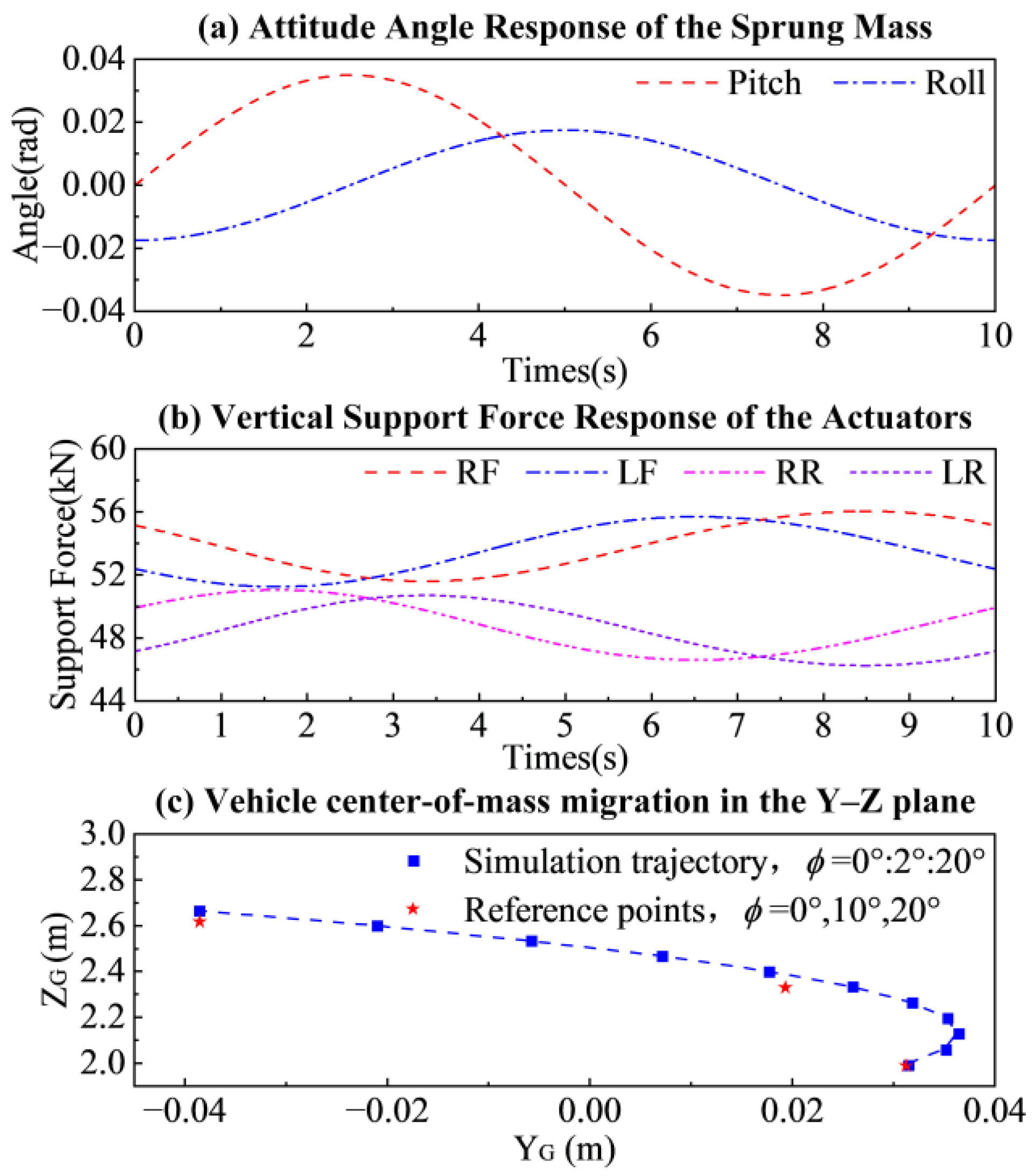
As shown in Figure 4a, under the periodic active displacement input of the actuators, both the pitch angle and roll angle of the sprung mass exhibit periodic variations. This indicates that the posture estimation model based on actuator active displacement can effectively reflect the regulating effect of the active suspension system on the posture of the sprung mass. Figure 4b shows the variation of the vertical support forces of the four actuators with the posture of the sprung mass, exhibiting dynamic variation patterns with different amplitudes and phases. This indicates that the coupled posture motion of the sprung mass leads to load redistribution among the four support positions, thereby verifying the effectiveness of the vertical support force calculation model. Figure 4c illustrates the variation trend of the whole-vehicle center of mass in the Y Z plane as the boom posture angle increases from 0 to 20 . It can be seen that the simulated trajectory is close to the reference points at the corresponding posture angles, indicating that the simulation results can accurately reflect the effect of boom posture angle variation on the whole-vehicle center of mass. The simulation results demonstrate that the established simulation model can realize continuous calculation from actuator active displacement to sprung-mass posture and vertical support force, and can further obtain the variation trend of the whole-vehicle center of mass that is consistent with the reference values from the center-of-mass test bench, thereby verifying the rationality of the proposed simulation model and center-of-mass determination method.

4.2. Experimental Study

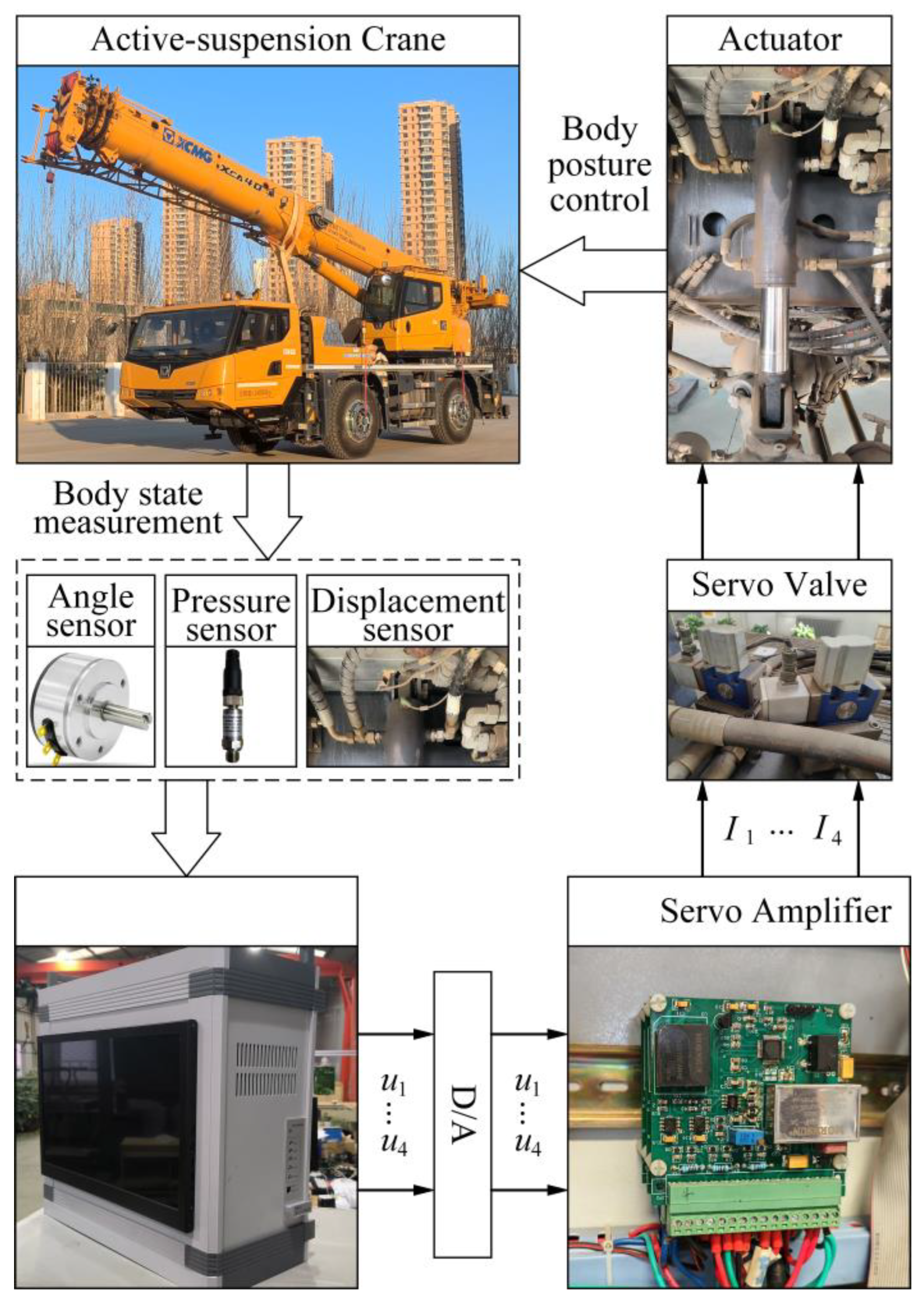
To further verify the applicability of the proposed multi-agent synchronization controller and whole-vehicle center-of-mass measurement method in real vehicles, full-vehicle experiments were conducted using a two-axle crane equipped with an active suspension system as the experimental platform. The experimental vehicle integrates active suspension hydraulic actuators, a hydraulic system, displacement sensors, pressure sensors, a posture-angle sensor, and a data acquisition system. Among them, the displacement sensors are used to measure the actual displacement of each actuator, the pressure sensors are used to calculate the vertical support force exerted by each actuator on the sprung mass, the posture-angle sensor is used to record the boom posture angle, and the data acquisition system is used to synchronously record displacement, support force, and posture information during the experiment.
The experimental data acquisition and whole-vehicle CoM coordinate determination procedure are shown in Figure 5. The main experimental steps are organized as follows. First, the boom is adjusted to the target posture angle. Second, the prescribed active displacement input is applied to the actuators according to the designed time sequence. Third, after the vehicle reaches a stable support state, the actuator displacement, actuator pressure, and boom posture-angle data are synchronously collected, followed by signal preprocessing and steady-state data-segment extraction. Then, the actuator pressures are converted into vertical support forces acting on the sprung mass, and the CoM coordinates of the sprung mass are determined using the support-force equilibrium relationships and the mass reaction method. Finally, the whole-vehicle CoM coordinates are obtained through mass-weighted averaging combined with the unsprung-mass parameters. This experimental platform enables integrated validation of active suspension actuator control, support-force acquisition, and whole-vehicle center-of-mass determination. It should be noted that the active suspension controller in this study is mainly used for actuator displacement tracking and multi-actuator synchronization, rather than for directly prescribing or optimizing the vertical support-force distribution among the actuators. The support-force data used for CoM calculation are collected after the actuators reach the target position and the vehicle enters a stable support state. Under this condition, the support forces are mainly determined by the vehicle weight, the actual CoM position, the actuator mounting geometry, and the final posture of the sprung mass. The test-bench CoM coordinates are used only for offline error comparison and are not involved in the closed-loop control or support-force compensation process. To reduce the influence of hydraulic friction and path-dependent hysteresis on support-force identification, the target position is approached from two directions in the experiment, and the steady-state support forces are averaged.
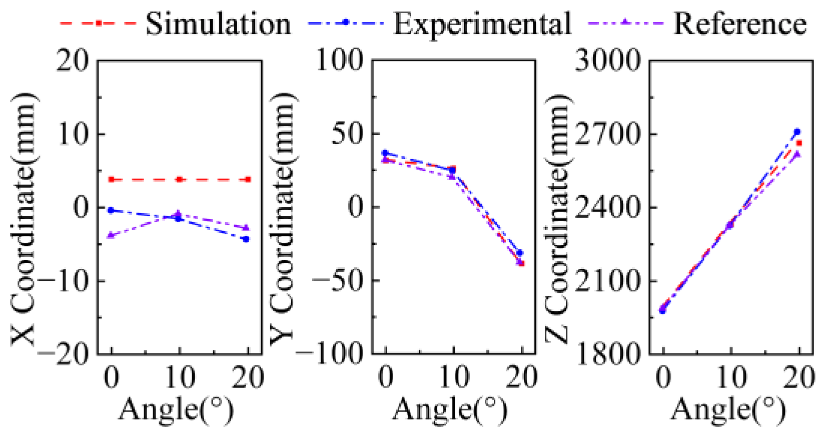
To distinguish the center-of-mass coordinates from different sources, the reference CoM coordinates, the full-vehicle measured CoM coordinates, and the simulated CoM coordinates under the k -th posture condition are denoted as r C , k r , r C , k e , and r C , k s , respectively.
The experimental study includes a full-vehicle validation experiment of the synchronization controller and an experiment for determining the whole-vehicle CoM coordinates. The synchronization-controller experiment is used to analyze the influence of the proposed multi-agent synchronization controller on actuator coordinated motion and vertical support-force distribution, whereas the CoM-coordinate determination experiment is used to verify the feasibility and accuracy of the proposed actuator-support-force-based method for determining whole-vehicle CoM coordinates under real-vehicle conditions. In the full-vehicle validation experiment of the synchronization controller, tests were carried out under two conditions, namely with and without the synchronization controller. By comparing the variations in the vertical support forces of the four actuators under these two conditions, the improvement in actuator motion consistency and load-distribution balance brought by the synchronization controller was analyzed. In the whole-vehicle CoM-coordinate determination experiment, three boom posture angles corresponding to the reference CoM coordinates were selected. Under each boom posture angle, the vertical support forces of the four actuators were collected, and the whole-vehicle CoM coordinates were determined according to the proposed method. Subsequently, the measured full-vehicle values were compared with the simulated values and the reference values to verify the engineering applicability of the proposed method. The structural parameters of the experimental vehicle are listed in Table 1.
In the full-vehicle experiments, the active displacement input of the actuators was designed according to the actual operating characteristics of the hydraulic actuators. Because non-ideal factors such as sealing friction, guide friction, and Coulomb friction exist during the displacement adjustment process of the hydraulic cylinders, and because the friction direction is related to the direction of motion, the support force obtained by an actuator near the same static displacement may be affected by the loading path. To reduce the influence of friction hysteresis and path-dependent bias on support-force identification, a symmetric reciprocating displacement loading scheme was adopted, so that the actuators entered the mid-position equilibrium region from the negative stroke side and the positive stroke side, respectively, and the support force was collected during the steady stage. Subsequently, the support forces obtained in the two steady stages were averaged and taken as the equivalent support force of the actuator at the mid-position state. This treatment can, to a certain extent, offset the friction bias caused by changes in the motion direction of the hydraulic cylinder, thereby improving the stability and reliability of CoM-coordinate determination based on support forces. The stroke range of the hydraulic actuators is from 110 mm to 110 mm. When determining the X - and Y -direction coordinates of the CoM of the sprung mass, identical displacement commands were assigned to the four actuators. The initial position was first set to 80 mm, and then displacement loading was applied according to the time sequence shown in Table 2. Through this loading scheme, the steady support forces of the actuators entering the mid-position state from the negative stroke side and the positive stroke side can be obtained, respectively. When determining the Z -direction coordinate of the CoM of the sprung mass, the four actuators were kept at 60 mm, and the steady-state support force of the left-side actuators was collected. Then, the right-side actuators were commanded to increase linearly from 60 mm to 60 mm, and after the vehicle posture became stable, the support force of the left-side actuators was collected again. The corresponding displacement loading sequence is shown in Table 3.
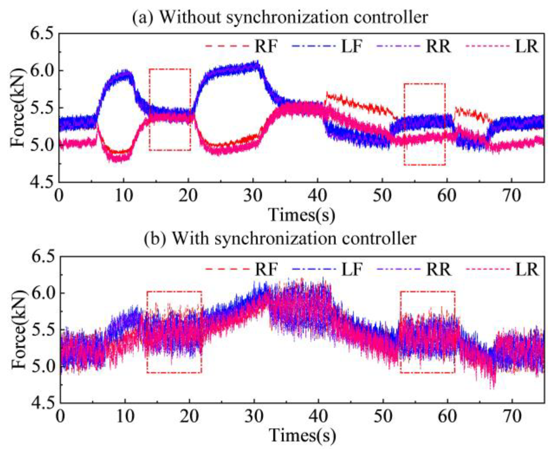
To verify the effectiveness of the proposed multi-agent synchronization controller in the real-vehicle system, the active displacement input shown in Table 2 was applied to the four actuators under two conditions, namely with and without the synchronization controller, and the vertical support-force responses of the actuators were collected. Figure 6 shows the support-force variation curves of the four actuators under these two control conditions. As shown in Figure 6a, when the synchronization controller is not activated, the support-force variation trends of the four actuators differ significantly. Specifically, the support forces of the left-front and right-rear actuators first increase and then decrease, whereas those of the right-front and left-rear actuators first decrease and then increase, indicating that actuator asynchrony exists under the same active displacement input. Because of the asynchronous actuator motion, the sprung mass undergoes additional load transfer during posture adjustment, causing some actuators to bear larger support forces while the support forces of the other actuators decrease correspondingly. As shown in Figure 6b, after the synchronization controller is activated, the variation trends of the support forces of the four actuators become much more consistent. Compared with the condition without the synchronization controller, the differences in support force among the actuators are reduced and the load distribution becomes more balanced, indicating that the synchronization controller can effectively improve the coordinated motion of the four actuators and reduce the additional load transfer caused by asynchronous motion. In addition, the red dashed box in the figure indicates the data acquisition region for CoM calculation. It can be seen that, without the synchronization controller, the data in the acquisition region are relatively scattered, which may increase the uncertainty of support-force identification and further affect the accuracy of CoM-coordinate determination. The experiment verifies that the proposed multi-agent synchronization controller can not only improve actuator displacement synchronization performance, but also enhance the coordination of four-point vertical support-force distribution in the active suspension system of the real vehicle.
For the determination of the whole-vehicle CoM coordinates, experiments were conducted under three operating conditions with boom posture angles of 0 , 10 , and 20 . For each boom posture angle, the active displacement input was first applied according to the time sequence described in Table 2. The steady support forces of the four actuators at the mid-position state were collected, and the average value of the support forces obtained in the two steady stages was taken as the equivalent support force. The X - and Y -direction coordinates of the CoM of the sprung mass were then determined using the proposed measurement method. Unlike the horizontal coordinates, the CoM height of the sprung mass was determined using the mass reaction method. According to the time sequence described in Table 3, active displacement loading was applied to the actuators, and the steady support forces of the left-side actuators before and after posture adjustment were collected. The CoM height of the sprung mass was then obtained using the mass reaction method. Finally, the whole-vehicle CoM coordinates were obtained by mass-weighted averaging in combination with the known unsprung mass and its CoM coordinates.
The experimental results are shown in Figure 7, which compares the real-vehicle measured values, simulated values, and reference values of the whole-vehicle CoM coordinates under the three boom posture angles. As shown in the figure, the whole-vehicle CoM coordinates vary significantly with the increase in the boom posture angle. Since the boom mainly moves in the Y - Z plane, its posture variation primarily affects the Y - and Z -direction coordinates of the whole-vehicle CoM. This variation pattern is consistent with the vehicle structural characteristics and the boom motion form. The comparison among the three types of results shows that the real-vehicle measured values obtained by the proposed method are close to the reference values under different postures. This indicates that the CoM determination method based on actuator support forces and mass-weighted averaging can accurately reflect the CoM position of the vehicle under the corresponding stable operating condition. Meanwhile, the simulated values show a variation trend similar to that of the reference values, indicating that the simulation model established above can reasonably describe the whole-vehicle CoM variation caused by changes in the boom posture angle.
To further quantify the difference between the real-vehicle measured results and the reference values, the measurement errors in the three coordinate directions were calculated as follows:
e C , k e = r C , k e r C , k r
where r C , k e denotes the real-vehicle measured value obtained by the proposed method, and r C , k r denotes the reference value. The coordinate errors under each posture condition are listed in Table 4.
As shown in Table 4, certain deviations exist between the real-vehicle measured results and the reference values under the three boom postures, but the errors in all coordinate directions remain within a relatively small range. These deviations are reasonable because the real-vehicle experiments are affected by disturbance factors such as hydraulic cylinder friction, pressure sensor measurement errors, and structural assembly errors. Overall, as the boom posture angle increases, the influence on the determination of the whole-vehicle CoM coordinate in the Z -axis direction becomes more pronounced, with an error of 92.45 mm. Compared with the reference CoM height of 2614 mm, the relative error is approximately 3.54 % , which is relatively low for the scale of the experimental vehicle used in this study. The experimental results verify the feasibility and engineering applicability of the proposed method for real-vehicle CoM coordinate determination.

5. Discussion

The proposed method is not intended for continuous real-time tracking of the vehicle CoM trajectory, but for reacquiring CoM parameters after an engineering vehicle with active suspension enters a stable operating condition. Compared with conventional test-bench measurement methods, this approach uses the vehicle’s own actuators and sensor system to determine CoM coordinates, thereby supporting active suspension control-parameter updating after changes in payload state or upper-structure posture. Compared with dynamic estimation methods relying on vehicle excitation, Kalman filtering, or multi-sensor fusion, the proposed method is more suitable for low-speed, static, or quasi-static stable conditions. In this process, the multi-agent synchronization controller improves actuator displacement consistency and reduces additional load transfer caused by asynchronous motion, thereby enhancing the stability of vertical support-force identification and the reliability of CoM coordinate determination.
The experimental results show that, under boom posture angles of 0 , 10 , and 20 , the whole-vehicle CoM coordinates obtained by the proposed method are close to the test-bench reference values, indicating that the method can reflect CoM migration caused by upper-structure posture variation. The relatively larger Z -direction error under the 20 condition may be attributed to the sensitivity of the mass reaction method to hydraulic cylinder friction, pressure measurement errors, posture stability, and structural assembly errors. In addition, the experimental validation of this study is still subject to certain scope limitations. The simulation and full-vehicle experimental results are evaluated using the test-bench CoM coordinates as reference values. Therefore, the present validation mainly focuses on the tested two-axle crane equipped with active suspension under three stable boom posture conditions, namely 0°, 10°, and 20°. Since reliable reference CoM coordinates under other boom postures, payload masses, payload positions, and vehicle configurations are not yet available, these conditions are not quantitatively evaluated in this study. Future work will combine additional benchmark measurements to further verify the applicability of the proposed method under different vehicles, payload states, uneven ground, and quasi-dynamic operating conditions.

6. Conclusions

(1)
This study proposes a method for determining the whole-vehicle center-of-mass coordinates of heavy engineering vehicles equipped with active suspension. In this method, the vehicle mass is divided into the sprung mass and the unsprung mass. The center of mass of the sprung mass is determined using actuator support forces and the mass reaction method, while the unsprung mass and its center-of-mass coordinates are treated as known parameters in the whole-vehicle center-of-mass calculation. By applying mass-weighted averaging to the centers of mass of the sprung and unsprung masses, the proposed method can obtain the whole-vehicle center-of-mass coordinates under different boom postures, providing a feasible approach for center-of-mass coordinate determination in engineering vehicles with active suspension.
(2)
A simulation model was established to describe the relationship among actuator active displacement input, sprung-mass posture, vertical support force, and whole-vehicle center-of-mass migration. The simulation results show that actuator active displacement can induce pitch and roll posture variations of the sprung mass, which further leads to redistribution of the vertical support forces among the four actuators. The simulated center-of-mass results under different boom postures show good consistency with the reference values, indicating that the established simulation model can reasonably reflect the whole-vehicle center-of-mass migration caused by changes in boom posture.
(3)
Full-vehicle experiments were conducted to verify the effectiveness of the multi-agent synchronization controller and the whole-vehicle center-of-mass determination method. The experimental results show that, after the synchronization controller is activated, the consistency of the support-force responses of the four actuators is improved, and the support load distribution becomes more coordinated. Under the boom posture angles of 0°, 10°, and 20°, the whole-vehicle CoM coordinates obtained by the proposed method agree well with the reference values, verifying the feasibility of the method for the tested vehicle under stable operating conditions.

Author Contributions

Conceptualization, J.C. and D.Z.; methodology, J.C. and D.Z.; software, J.C., Z.Z. and H.J.; validation, J.C., L.W. and Z.Z.; formal analysis, J.C.; investigation, J.C.; resources, D.Z.; data curation, J.C. and X.X.; writing—original draft preparation, J.C.; writing—review and editing, J.C., H.J. and Z.Z.; visualization, J.C.; supervision, D.Z.; project administration, D.Z.; funding acquisition, D.Z. All authors have read and agreed to the published version of the manuscript.

Funding

This research was funded by the National Natural Science Foundation of China, grant number U24A6008, and the Natural Science Foundation of Hebei Province, grant number E2024203257. The APC was funded by the authors.

Data Availability Statement

The data presented in this study are available from the corresponding author upon reasonable request.

Conflicts of Interest

Author Zhijian Zhang was employed by Tai’an Aerospace Special Vehicle Co., Ltd. The remaining authors declare no conflicts of interest. The funders had no role in the design of the study; in the collection, analyses, or interpretation of data; in the writing of the manuscript; or in the decision to publish the results.

Abbreviations

The following abbreviations are used in this manuscript:
CoMCenter of mass
PIDProportional-integral-derivative
NNNeural network
MASMulti-agent system
EKFExtended Kalman filter
UKFUnscented Kalman filter
IMUInertial measurement unit
GPSGlobal positioning system
RMSERoot-mean-square error
MTEMean tracking error

References

  1. Otremba, F.; Navarrete, J.A.R. Assessing Rail Damage in Turns due to Lateral Load Transfer. In Proceedings of ASME 2024 International Mechanical Engineering Congress and Exposition, IMECE2024; ASME: New York, NY, USA, 2024; Volume 11. [Google Scholar]
  2. Navarrete, J.A.R.; Otremba, F.; Guzmán, A.A.L. Liquid Cargo Effect on Load Transfer under Orthogonal Accelerations. Int. J. Heavy Veh. Syst. 2022, 29, 213–226. [Google Scholar] [CrossRef] [Scilit]
  3. Li, A.; Chen, Y.; Lin, W.C.; Du, X.Y. Estimation of Three-Dimensional Center of Gravity Relocation for Ground Vehicles with Tire Blowout. In 2022 American Control Conference, ACC; IEEE: New York, NY, USA, 2022. [Google Scholar]
  4. Choi, Y.H.; Kwon, K.A.; Lee, C.H. Experimental Investigation on a Static Rollover Angle Model for Commercial Vehicle: New Measurement Method and Theoretical Model for Double Rear Axle Vehicle. J. Mech. Sci. Technol. 2022, 36, 4943–4951. [Google Scholar] [CrossRef] [Scilit]
  5. Xu, Q.J.; Fu, R.; Wu, F.W.; Wang, B.Y. Roadside Estimation of a Vehicle’s Center of Gravity Height Based on an Improved Single-Stage Detection Algorithm and Regression Prediction Technology. IEEE Sens. J. 2021, 21, 24520–24530. [Google Scholar] [CrossRef] [Scilit]
  6. Chang, J.; Zhao, D.; Jiang, H.; Ma, Y.; Li, S. Research on Vehicle Center of Mass Measurement Method Based on Active Suspension; Saman, H., Peng, Y., Zhao, D., Bian, Y., Eds.; Springer Nature: Singapore, 2026; pp. 1101–1113. [Google Scholar]
  7. Grakovski, A.; Pilipovecs, A. Weigh-in-Motion by Fibre-Optic Sensors: Problem of Measurement Errors Compensation for Longitudinal Oscillations of a Truck. In Reliability and Statistics in Transportation and Communication; Springer: Cham, Switzerland, 2018. [Google Scholar]
  8. Sun, C.; Wang, C.; Deng, Z.J.; Cao, D.P. Dimensionless Model-Based System Tracking Via Augmented Kalman Filter for Multiscale Unmanned Ground Vehicles. IEEE-ASME Trans. Mechatron. 2021, 26, 600–610. [Google Scholar] [CrossRef] [Scilit]
  9. Park, G.; Choi, S.B. An Integrated Observer for Real-Time Estimation of Vehicle Center of Gravity Height. IEEE Trans. Intell. Transp. Syst. 2021, 22, 5660–5671. [Google Scholar] [CrossRef] [Scilit]
  10. Wan, W.K.; Feng, J.G.; Song, B.; Li, X.X. Huber-Based Robust Unscented Kalman Filter Distributed Drive Electric Vehicle State Observation. Energies 2021, 14, 750. [Google Scholar] [CrossRef] [Scilit]
  11. Wang, P.; Fan, X.B.; Chen, X.B.; Yi, J.A.; He, S.W. UKF Estimation Method of Centroid Slip Angle for Vehicle Stability Control. Int. J. Control Autom. Syst. 2023, 21, 2259–2266. [Google Scholar] [CrossRef] [Scilit]
  12. Wu, F.W.; Sun, C.; Li, H.R.; Zheng, S.F. Real-Time Center of Gravity Estimation for Intelligent Connected Vehicle Based on HEKF-EKF. Electronics 2023, 12, 386. [Google Scholar] [CrossRef] [Scilit]
  13. Zhang, Z.G.; Yin, G.D.; Wu, Z.X. Joint Estimation of Mass and Center of Gravity Position for Distributed Drive Electric Vehicles Using Dual Robust Embedded Cubature Kalman Filter. Sensors 2022, 22, 10018. [Google Scholar] [CrossRef] [Scilit] [PubMed]
  14. Pang, G.Q.; Xiao, Z.Q.; Cai, Z.W.; Wang, P. Study on Centroid Height Prediction of Non-Rigid Vehicle Based on Deep Learning Combined Model. Sensors 2025, 25, 5692. [Google Scholar] [CrossRef] [Scilit] [PubMed]
  15. Wüest, V.; Kumar, V.; Loianno, G. Online Estimation of Geometric and Inertia Parameters for Multirotor Aerial Vehicles. In 2019 International Conference on Robotics and Automation (ICRA); IEEE: New York, NY, USA, 2019. [Google Scholar]
  16. Xia, G.; Zhang, C.H.; Tang, X.W.; Zhang, Y.; Zhao, L.F. Center of Gravity Position Estimation of Counterbalanced Forklift Truck Based on Multi Model Data Fusion. Int. J. Automot. Technol. 2023, 24, 1335–1347. [Google Scholar] [CrossRef] [Scilit]
  17. Hofmann, R.; Hosseini, B.; Fang, X.; Rhein, J.L.; Sax, F.; Holzapfel, F.; Maier, L.; Barth, A. Center of Gravity Estimation Using Multiple Accelerometers. In AIAA SCITECH 2024 Forum; AIAA: Reston, VA, USA, 2024. [Google Scholar]
  18. Fu, Z.J.; Hu, Q.; Li, B. Adaptive Online Estimation of Centre of Gravity Height for Commercial Vehicles. Int. J. Heavy Veh. Syst. 2021, 28, 206–225. [Google Scholar] [CrossRef] [Scilit]
  19. Heinemann, N.; Henning, K.U.; Sawodny, O. Center of Gravity Height and Load Estimation in Vehicle Roll Dynamics. IFAC PapersOnline 2025, 59, 311–316. [Google Scholar] [CrossRef] [Scilit]
  20. Wittmer, K.; Sawodny, O.; Henning, K.U. Model-Based Estimation of Vehicle Center of Gravity Height and Load. J. Dyn. Syst. Meas. Control-Trans. ASME 2023, 145, 051001. [Google Scholar] [CrossRef] [Scilit]
  21. Chen, J.X.; Du, X.; Pan, Z.R.; Fei, Z.Y.; Sun, X.M. High Sensitivity Synchronization Motion Control for an Aero-Engine Dual-Cylinder Hydraulic System. IEEE Trans. Intell. Transp. Syst. 2025, 26, 2573–2581. [Google Scholar] [CrossRef] [Scilit]
  22. Fanliang, M.; Hao, Y.; Haas, C.; Schmitz, K. Robust Backstepping Control via Tracking Differentiator for Electro-Hydraulic Load Simulator Based on Velocity Synchronization. Control Eng. Pract. 2025, 158, 106279. [Google Scholar] [CrossRef] [Scilit]
  23. Ma, T.B.; Guo, X.X.; Su, G.Y.; Deng, H.S.; Yang, T. Research on Synchronous Control of Active Disturbance Rejection Position of Multiple Hydraulic Cylinders of Digging-Anchor-Support Robot. Sensors 2023, 23, 4092. [Google Scholar] [CrossRef] [Scilit] [PubMed]
  24. Sun, C.G.; Dong, X.X.; Li, J.P. Cross-Coupled Sliding Mode Synchronous Control for a Double Lifting Point Hydraulic Hoist. Sensors 2023, 23, 9387. [Google Scholar] [CrossRef] [Scilit] [PubMed]
  25. Zhou, Y.; Zhang, X.Y.; Helian, B.; Chen, Z.; Yao, B. Adaptive Robust Synchronization Control of an Electro-Hydraulic Dual-Cylinder System with Dynamic Thrust Allocation. IEEE-ASME Trans. Mechatron. 2025, 30, 2880–2888. [Google Scholar] [CrossRef] [Scilit]
  26. Stosiak, M.; Karpenko, M.; Skačkauskas, P.; Deptuła, A. Identification of Pressure Pulsation Spectrum in a Hydraulic System with a Vibrating Proportional Valve. J. Vib. Control 2024, 30, 4917–4930. [Google Scholar] [CrossRef] [Scilit]
  27. Dzakmic, S.; Ramdedovic, A.; Sabanovic, A. Uncertain Systems Motion Synchronization. IEEE Access 2023, 11, 125439–125451. [Google Scholar] [CrossRef] [Scilit]
  28. Murugesan, S.; Ishizaki, T.; Liu, Y.C. Resilient Annular Finite-Time Synchronization for Master-Slave Systems under Scaling Attacks. IET Control Theory Appl. 2023, 17, 2458–2473. [Google Scholar] [CrossRef] [Scilit]
  29. Qin, T.; Ma, Y.X.; Li, Y.H.; Quan, L. Torque Equilibrium Position Closed-Loop Control of Dual Electric Motors Swing System for Large Mining Excavator. Mechatronics 2023, 95, 103035. [Google Scholar] [CrossRef] [Scilit]
  30. Duan, Z.Y.; Wei, A.R.; Zhang, X.F.; Sun, B.; Zhao, J.S. Prescribed Performance Secure Synchronization for Nonlinear Heterogeneous Multi-Agent Systems under Multiple Attacks. J. Frankl. Inst. 2025, 362, 108114. [Google Scholar] [CrossRef] [Scilit]
  31. Li, Y.; Lu, Y.; Wu, Y. Fault Estimation and Consensus Tracking of Multi-Agent Systems Based on Intermediate Estimator. Inf. Sci. 2023, 647, 119422. [Google Scholar] [CrossRef] [Scilit]
  32. Wu, Y.X.; Meng, D.Y. Synchronizability-Based Distributed Learning Control for Multi-Agent Systems. IEEE Trans. Circuits Syst. II-Express Briefs 2024, 71, 2109–2113. [Google Scholar] [CrossRef] [Scilit]
  33. Li, Y.; He, S.; Xie, B.; Zhong, W.; Lu, Y. Reinforcement Learning Neural Network Observer-Based Adaptive Optimal Time-Varying Formation Control for Uncertain Multi-Agent Systems with External Disturbance. IEEE Trans. Autom. Sci. Eng. 2026, 23, 10186–10200. [Google Scholar] [CrossRef] [Scilit]
  34. Zhang, Y.; Ma, S.P.; Wu, Y.B. Adaptive Fault-Tolerant Practical Prescribed-Time Bipartite Synchronization for Nonlinear Multi-Agent Systems. J. Frankl. Inst. 2026, 363, 108329. [Google Scholar] [CrossRef] [Scilit]
  35. Li, Y.; He, S.; Xie, B.; Zhong, W. Enhanced Robustness in Simultaneous Fault Estimation and Distributed Fault-Tolerant Consensus Tracking Control for Multiagent Systems Utilizing Extended Observer Approach. IEEE Trans. Syst. Man Cybern. Syst. 2026, 56, 1721–1735. [Google Scholar] [CrossRef] [Scilit]
Figure 1. Schematic diagram of center-of-mass determination.
Actuators 15 00406 g001
Figure 2. Structure of the composite controller.
Actuators 15 00406 g002
Figure 3. Analysis of actuator displacement tracking and synchronization performance.
Actuators 15 00406 g003
Figure 4. Vertical support force calculation and simulated whole-vehicle center-of-mass results.
Actuators 15 00406 g004
Figure 5. Experimental platform and center-of-mass determination procedure.
Actuators 15 00406 g005
Figure 6. Comparison of actuator support-force variations with and without the synchronization controller.
Actuators 15 00406 g006
Figure 7. Comparison of whole-vehicle center-of-mass coordinates.
Actuators 15 00406 g007
Table 1. Main structural parameters of the experimental vehicle.
ParametersSymbolValue/Unit
Main-body massMb12,608 kg
Boom massMa8247 kg
Unsprung massMu3145 kg
Boom lengthL10,600 mm
Lateral distance between left and right actuatorsa1445 mm
Wheelbaseb3505 mm
Actuator stroke ranges±110 mm
Center-of-mass coordinates of the unsprung massru(0.89, 25.5, 629.6) mm
Table 2. Active displacement input sequence of the actuators.
Time Interval (s)Target Displacement (mm)Motion State
0–10−80Initial displacement holding
10–15−80 → 0Linear increase
15–250Steady-state data acquisition
25–350 → 80Linear increase
35–4580Stroke-position holding
45–5580 → 0Linear decrease
55–650Steady-state data acquisition
65–700 → −80Linear decrease
Table 3. Displacement input sequence for the center-of-mass height measurement experiment.
Time Interval (s)Left Actuator Command (mm)Right Actuator Command (mm)Motion State
0–10−60−60Initial steady-state data acquisition
10–15−60−60 → 60Linear increase of the right-side actuator
≥15−6060Post-adjustment steady-state data acquisition
Table 4. Coordinate errors between the real-vehicle measured results and the reference values.
Boom Attitude Angle e x e /mm e y e /mm e z e /mm
3.434.80−10.51
10°−0.674.85−1.70
20°−1.466.2092.45
Disclaimer/Publisher’s Note: The statements, opinions and data contained in all publications are solely those of the individual author(s) and contributor(s) and not of MDPI and/or the editor(s). MDPI and/or the editor(s) disclaim responsibility for any injury to people or property resulting from any ideas, methods, instructions or products referred to in the content.