3.1. Digital Model Construction
Angle-steel towers have complex three-dimensional structures. Their components, such as beams, columns and bolts, are densely distributed and interconnected. This brings great challenges to robotic path planning and collision avoidance [
21,
22]. Therefore, accurate modeling of these components is crucial. The fidelity of the digital model directly influences the safety and reliability of robotic path planning [
23]. In this study, the solution is to use Unity3D (version 2021.3.26f1c1) as the physics engine for reconstructing and describing high-altitude operations. Direct modeling in Unity3D is not practical because of the complex and numerous components. Therefore, some auxiliary modeling tools are used to build accurate and compatible models.
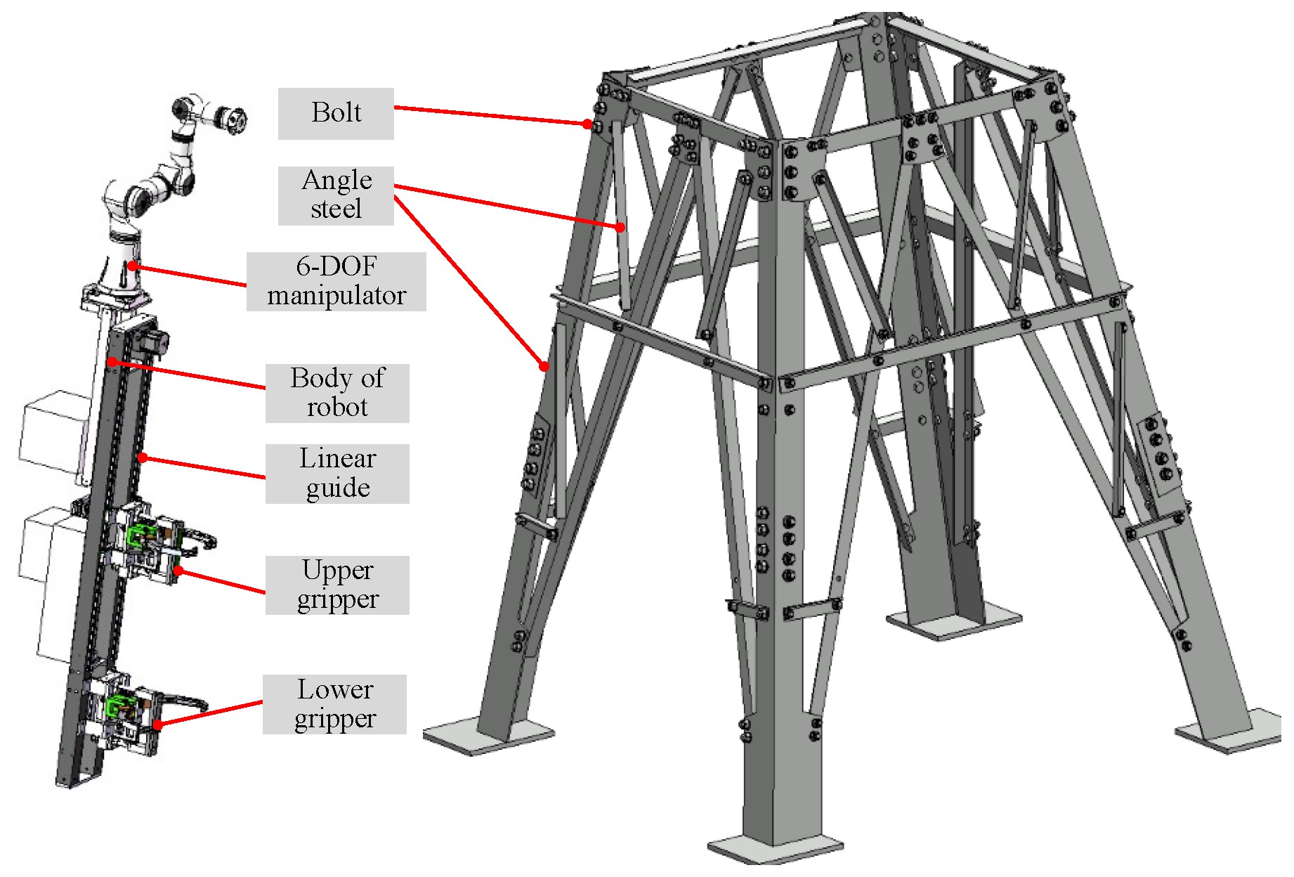
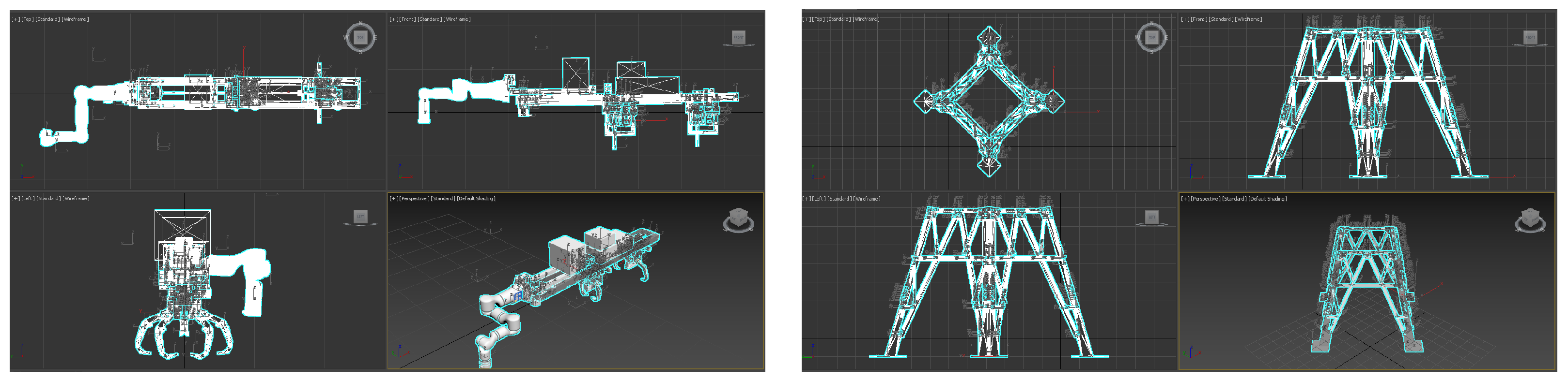
The tower geometry is reconstructed from high-precision lofting models using TMA software. The robot model, which includes the climbing mobile platform and the manipulator, is built in professional 3D mechanical design software such as SolidWorks 2021. 3ds Max software is used as an intermediate platform for the format conversion and optimization of the tower geometry and the robot model, as shown in
Figure 3. Several preprocessing steps are applied before integration into Unity3D:
Model simplification: Redundant meshes and hidden components are removed to reduce polygon count.
Coordinate alignment: Model axes are rotated and adjusted to match the left-handed coordinate system in Unity3D.
Scale correction: Units are standardized in 3ds Max to ensure a 1:1 scale correspondence after import.
Through this workflow, a digital twin environment of the tower–robot system is established, providing a basis for path planning and collision detection. The accuracy of physical equipment models may degrade after multiple layers of software conversion. However, the digital environment for high-altitude operations has stringent accuracy requirements. Therefore, this study adopts a model registration method based on PL-ICP [
24] method to ensure model fidelity.
Point cloud data of the digital twin model are read from Unity3D. Meanwhile, the point cloud data of the original physical model are collected separately. These two datasets are used to obtain the initial transformation matrix. Then, the nearest-neighbor points of each point in the original model are identified in the digital twin model by using the nearest-neighbor method, and points with large registration errors are removed. The objective function is constructed as follows:
where
J denotes the objective function,
and
represent the rotation matrix and translation vector at the (k + 1)-th iteration respectively;
N is the number of corresponding point pairs,
and
represent the unit normal vector and the vector of the i-th point in the original physical model’s point cloud respectively, and
is the vector of the nearest-neighbor point corresponding to
in the digital twin model.
The registration accuracy is quantitatively evaluated using the root mean square error (RMSE) of the point-to-plane distance:
The RMSE of the raw tower model before registration is measured as 16.74 mm, which exceeds the 2 mm accuracy requirement. After PL-ICP-based registration, the RMSE is reduced to 0.62 mm, meeting the precision demand for high-altitude operation tasks.
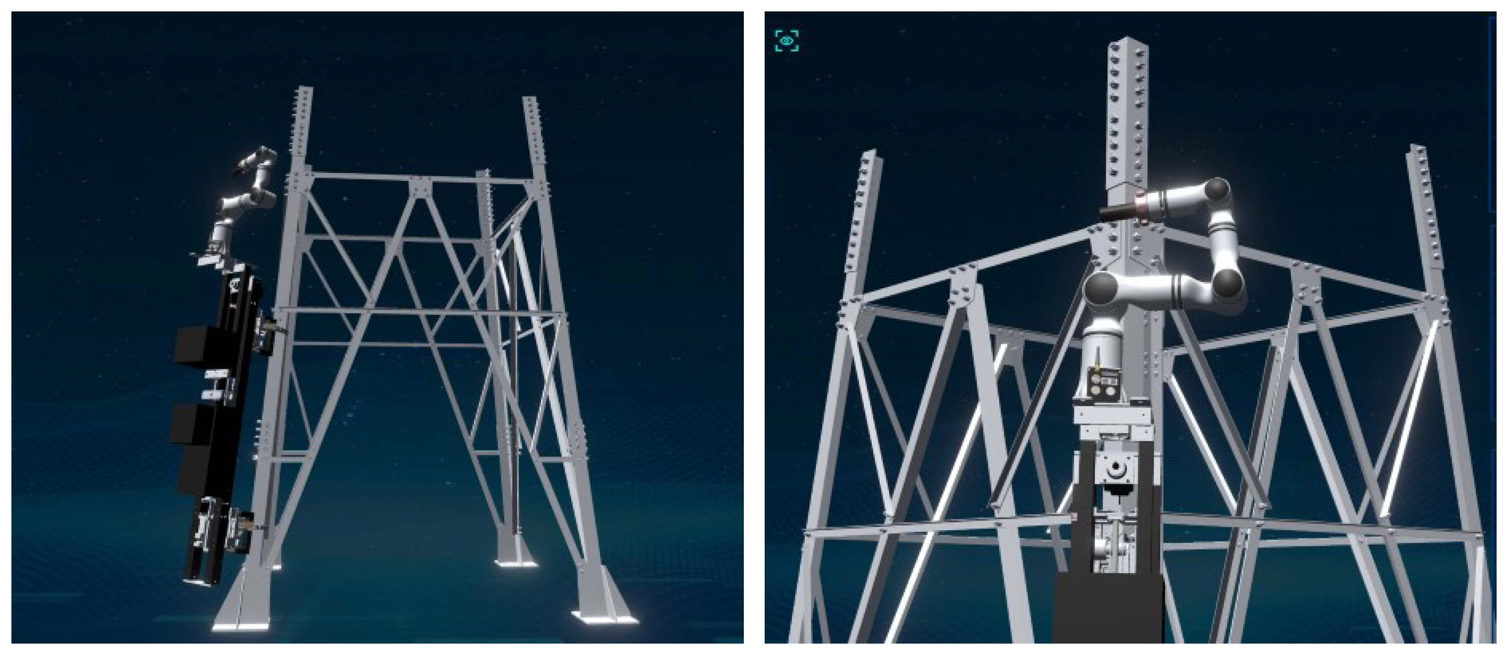
The verified high-fidelity digital model is saved and displayed in Unity3D platform, as shown in
Figure 4.
After importing the high-precision registered model into Unity3D, collision properties are assigned to the model to support the subsequent path planning. In Unity3D, available collider types include simple geometric primitives (Sphere Collider, Box Collider, Capsule Collider), Compound Collider, and Mesh Collider. In this work, Mesh Collider is adopted for collision detection of complex angle-steel components. This collider generates a tightly fitted, shape-adaptive collision envelope that conforms to the irregular 3D geometry of each structural part. Compared with simple geometric approximations, Mesh Collider achieves pixel-level accurate collision detection. When a collision is detected, a trigger signal is generated to instruct the planning algorithm to adjust its spatial expansion direction for obstacle avoidance.
3.2. Bidirectional Beetle Antennae Search Mechanism
In high-dimensional environments, conventional RRT* algorithms often suffer from slow convergence due to random sampling, which requires extensive computation and a large number of iterations. For the digital twin environment constructed in this study, the standard RRT* generally requires more than 4000 iterations to obtain a feasible path. To enhance convergence efficiency, a BAS mechanism is incorporated to guide the sampling process adaptively.
The BAS algorithm is inspired by the foraging behavior of longhorn beetles. A beetle perceives the intensity of environmental stimuli through two antennae and moves toward the side with a stronger signal. By iteratively adjusting its direction according to this sensory difference, the beetle converges toward the optimal position.
To extend BAS for high-dimensional optimization, a step attenuation coefficient is introduced. A larger initial step promotes global exploration, whereas a gradually decaying step enables local refinement near the optimum. As the step decreases, the antenna spacing correspondingly shrinks, allowing the search process to transition smoothly from global to local exploration. Because only a few beetles are used, the computational burden remains low while maintaining high convergence speed.
For the 3D optimization problem considered here, let denote the beetle’s step length, denote the attenuation coefficient, and denote the antenna spacing. The search process can be described as follows.
First, the movement direction of the beetle is determined by
where
n is the dimensionality of the search space.
Then, the coordinates of the left antennae
and right antennae
are calculated as
where
represents the best-known position, and
(the distance between the two antennae) is defined as
.
Next, the objective function
is evaluated to measure the Euclidean distance between one’s position
X and the target position
:
The corresponding evaluations at the two antenna positions are
Finally, using the sign function
, the beetle updates its position according to
If
falls on the angle-steel tower components, the collision detection function of the digital engine will be triggered. Then, the search direction is recalculated by (
3). The iterative updates are performed by comparing
and
. If
, the best position is updated by
; otherwise, the step size is gradually reduced according to the attenuation rule until convergence is achieved.
3.3. Multi-Constraint Objective Function
To obtain a high-quality feasible path for the six-degree-of-freedom (6-DOF) manipulator, multiple constraints must be imposed to address obstacle avoidance and kinematic limitations. Unlike the original RRT* algorithm [
25], the proposed improved RRT* algorithm integrates an extended objective function evaluation into the nearest-neighbor search procedure. It traverses all nodes in the node list and selects the one with the minimum total cost for tree expansion. Specifically, the objective function
is augmented with three penalty terms to satisfy the requirements of tower inspection and maintenance tasks: the position cost, the optimization cost, and the operability cost.
The location cost
integrates both the current and cumulative distance costs to improve path efficiency. And the optimization cost
quantifies the variation in joint angles to maintain smooth motion during operations such as bolt tightening or component inspection. They are defined as:
where
j denotes the number of parent nodes in the tree, and
l represents the rotational degrees of freedom of the manipulator.
The operability cost represents the ability of the manipulator to move its end-effector flexibly within the tower’s narrow and obstacle-rich workspace. It is expressed as:
where
quantifies the manipulability of the configuration, and
represents the joint angles. A smaller value implies that the manipulator is close to a singular configuration, and a larger value corresponds to higher dexterity and motion flexibility. When its value is zero, the manipulator may suffer from structural stress or loss of controllability. Therefore, manipulability acts as an important indicator for judging whether the manipulator is in or near a singular pose.
The manipulability measure is defined as:
where
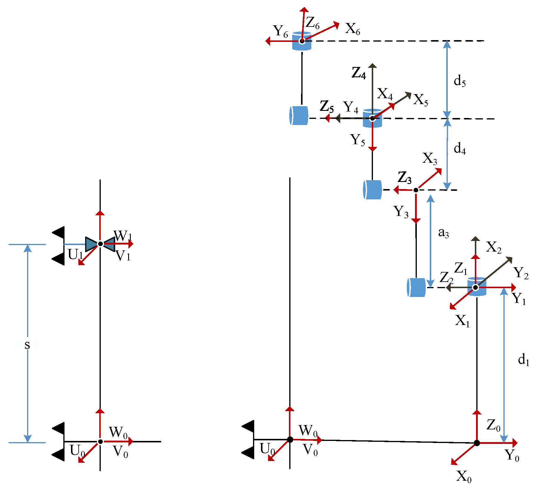
is the Jacobian matrix of the 6-DOF manipulator, derived from its kinematic model, and
represents the determinant operator.
Then, all cost terms are normalized to the range [0, 1] using min–max scaling to eliminate magnitude discrepancies. This ensures that no single term dominates the optimization due to unit or scale differences. The normalized cost is defined as:
where
,
,
, and
is the maximum manipulability measure over all feasible robot configurations.
Finally, the overall objective function is formulated as:
where
is a weighting coefficient to balances the optimization and operability costs. This balance ensures smooth motion via
while avoiding singularities via
in the tower environment, and
maintains path efficiency.
When , the optimization focuses on manipulability and singularity avoidance, which is suitable for obstacle-dense and constrained environments. When , the optimization emphasizes motion smoothness, generating more stable trajectories in open spaces. In practical implementation, one may first set to generate a collision-free and singularity-free feasible trajectory, and then gradually increase to improve the trajectory smoothness.
3.4. Informed RRT* Algorithm
The Informed RRT* algorithm introduces a heuristic sampling mechanism after an initial feasible path is obtained. Instead of sampling uniformly across the entire configuration space, the search is constrained within an ellipsoidal region centered between the start and goal. As the path cost decreases during iteration, the ellipsoid gradually contracts, focusing sampling on promising areas and speeding up convergence to the optimal solution.
The major axis
is set to the length of the current best path. The minor axis
is set to the Euclidean distance between the start and goal configurations, defined as
To generate samples uniformly within the ellipsoid, random points are first generated inside a unit sphere, then transformed into the target ellipsoidal domain. The transformation is realized through a rotation matrix
C and a scaling matrix
L. The rotation matrix
C is computed using the Kabsch [
26] algorithm, which applies singular value decomposition (SVD) to the normalized vector connecting the start and goal points. The scaling matrix
L is given by:
As the path is continuously optimized, the ellipsoid shrinks dynamically to concentrate sampling around the optimal trajectories.
3.5. BBI-RRT* Connect Algorithm Summary
The BBI-RRT* Connect algorithm (integrating bidirectional beetle antennae search, a multi-constraint objective function, and Informed RRT*) provides a efficient path planning framework for aerial work manipulators in complex angle-steel tower environments. The full procedure in pseudocode is summarized in Algorithm 1.
| Algorithm 1 BBI-RRT* Connect algorithm for high-altitude angle-steel tower operations. |
- 1:
Input: Digital twin model of angle-steel tower, start and goal positions, maximum iterations , BAS step size, attenuation coefficient - 2:
Output: Optimized collision-free path for the manipulator - 3:
Initialize iteration counter - 4:
Construct bidirectional BAS agents at start and goal positions - 5:
while
do - 6:
Update BAS agent positions to generate candidate sampling points - 7:
Evaluate candidate nodes using the multi-constraint objective function - 8:
Expand trees toward selected nodes, update parent nodes if necessary, and check collisions - 9:
If collision occurs, discard node and resample; otherwise, update tree structure - 10:
Attempt to connect the two trees to form an initial feasible path - 11:
if initial path is found then - 12:
Switch to Informed RRT* sampling within 3D ellipsoidal region defined by current best path - 13:
Refine path, update parent nodes, and optimize path cost - 14:
end if - 15:
- 16:
end while - 17:
Output the final optimized path
|
The theoretical analysis of computational overhead per iteration is supplemented as follow:
The BAS module only computes left/right antenna coordinates in 3D space, evaluates the Euclidean distance to the target, and updates the beetle position with collision checking. All operations are fixed and constant-time, so the overhead is .
The multi-constraint objective function includes position cost, smoothness cost, and manipulability cost. All calculations involve fixed dimension vectors and a 6 × 6 Jacobian matrix, with constant computation. The overhead is .
The Informed RRT* ellipsoid sampling uses fixed 3 × 3 matrix transformation from a unit sphere. All operations are constant-time, so the overhead is .
The nearest-neighbor search, parent reselection, and rewiring operations inherit from standard bidirectional RRT* Connect and remain , where N is the number of nodes.
Thus, the per iteration time complexity of BBI RRT* Connect is identical to that of traditional bidirectional RRT* Connect, i.e., . The extra overhead from BAS and the multi-constraint function is a small constant that does not change the asymptotic order.