Article

Improved Model Reference Adaptive Disturbance Suppression Control for Marine Canned Magnetic Bearings


1
Hubei East Lake Laboratory, Wuhan 430071, China
2
National Key Laboratory of Electromagnetic Energy, Naval University of Engineering, Wuhan 430033, China
3
School of Electrical and Electronic Engineering, Huazhong University of Science and Technology, Wuhan 430074, China
*
Author to whom correspondence should be addressed.
Actuators 2026, 15(2), 129; https://doi.org/10.3390/act15020129
Submission received: 13 January 2026 / Revised: 6 February 2026 / Accepted: 17 February 2026 / Published: 20 February 2026

Abstract

To overcome the limitations of conventional control strategies in simultaneously suppressing external sway disturbances and internal parameter variations—induced by strong eddy current effects in marine canned magnetic bearings (MBs)—this paper introduces an improved model reference adaptive control (MRAC) method. First, electromagnetic force and dynamic models of the marine canned MBs are developed, taking into account eddy current effects and oscillatory motion. On this basis, a state observer is designed to estimate the system’s unknown dynamics. A predictive error term is formulated to capture the combined influence of model uncertainties and external disturbances. An adaptive law is then applied to compensate for these unknown dynamics and external disturbances. Moreover, the stability of the marine canned MBs system under the proposed improved MRAC scheme is rigorously analyzed using Lyapunov stability theory. Simulation results confirm the effectiveness of the algorithm, showing that, compared with conventional PID control, the improved MRAC approach reduces rotor vibration by more than 53%, significantly strengthening the disturbance rejection performance of marine canned MBs.

1. Introduction

High-end, intelligent, and green technologies are key trends in marine equipment development. As an independent mode of transportation, ships typically incorporate dozens of fluid mechanical systems such as propellers and pumps for energy conversion, as well as the storage and transport of liquids and gases [1,2]. To support the strategic goal of becoming a maritime power, military and civilian sectors require higher hydraulic efficiency, lower vibration, better environmental performance, and improved maintainability of fluid machinery [3,4]. As a cutting-edge enabling technology, magnetic bearings (MBs) offer distinct advantages, including non-contact operation between stator and rotor, absence of lubrication needs, and active controllability, thereby playing an increasingly critical role in marine applications [5,6]. Currently, MBs have been widely adopted in terrestrial applications such as flywheel energy storage and compressors, primarily operating in vacuum or gaseous environments [7,8,9]. However, in shipboard fluid machinery, working media often contain water, coolants, or other liquids, and operational conditions are severe, posing significant challenges for the deployment of MBs. First, conventional anti-corrosion processes such as glue injection and varnish dipping are ineffective for core components like MBs and motors. Corrosion resulting from long-term operation not only degrades material properties but also produces particulate impurities, thereby directly compromising the safe and stable operation of fluid machinery [10]. Second, during ship navigation, fluid machinery experiences mechanical movements such as tilting and swaying along with the hull, which increase axial vibration of the MB’s rotor and reduce system stability, thereby compromising the safe and stable operation of fluid machinery [11]. To meet the stringent requirements for sealing and corrosion resistance, Study [12] proposed a canned MBs configuration that incorporates a metallic sleeve between the stator and rotor to fully isolate the iron core from the external environment, thereby improving corrosion resistance and sealing performance in liquid media. However, the metallic sleeve intensifies eddy current losses, degrades electromagnetic performance, and narrows the control bandwidth of the MBs. Consequently, developing high-efficiency control algorithms to enhance the control performance and environmental adaptability of canned MBs is of significant research value for advancing the application of MB technology in marine equipment.
Currently, global research on the control of canned MBs remains relatively limited. Reference [13] proposed a control scheme for MBs with a thin-walled solid rotor (analogous to a shielding sleeve), which achieves system dynamic decoupling via distributed drive control, thereby enhancing the control performance of MBs. Reference [14] developed a fractional-order model identification method for solid rotor-MBs systems, providing a foundational model for the precise control of MBs. In contrast, studies on MBs’ control algorithms for ship-type motion platforms are more abundant. Reference [15] proposed a sliding mode control method for MBs by accounting for base motion effects, which effectively suppresses base motion-induced responses. Reference [16] presented an MBs control strategy based on the constitutive relationship of viscoelastic materials for periodic base motion, and its effectiveness was validated through swing condition tests. Reference [17] introduced a base motion disturbance observation and suppression method for MBs using a disturbance observer, enabling high-performance vibration control of MBs without additional sensors. Reference [18] employed a composite control approach combining feedforward control and PID control to mitigate base motion-induced disturbances, improving rotor suspension accuracy. While the aforementioned studies offer insights into the high-performance control of marine canned MBs, they struggle to simultaneously address the dual challenges of the strong eddy current effect of the shielding sleeve and the impact of ship base motion on MBs. Reference [19] proposed a Lyapunov-Krasovskii functional composed of state decomposition components and a relatively small number of decision variables, and designed an H∞ controller. Reference [20] proposed a hybrid control method that combines the Model Reference Adaptive Control (MRAC) approach with the ESO disturbance estimation method.
To address the aforementioned challenges, this paper proposes a magnetic bearing control algorithm tailored to the characteristics of marine canned MBs based on MRAC. By integrating state observation with predictive error feedback, the proposed approach concurrently enhances the magnetic bearing’s adaptability to internal and external disturbances, thereby providing a feasible solution for the stable operation of marine canned MBs.

2. Mathematical Modeling of Canned MBs Considering Ship Rolling Motion

2.1. Modeling of Electromagnetic Forces

The MBs analyzed in this study are octopolar canned MBs, whose topological configuration is illustrated in Figure 1, with key parameters detailed in Table 1. In contrast to conventional MBs, canned MBs incorporate metal sleeves (hereafter referred to as shielding sleeves) installed on the inner surface of the stator and the outer surface of the rotor, respectively. This structural modification enhances corrosion resistance and sealing performance when the MBs operate in liquid or gaseous environments. However, the presence of metal shielding sleeves induces eddy currents under high-frequency magnetic fields, leading to significant eddy current losses and a degradation of the system’s dynamic response capability.
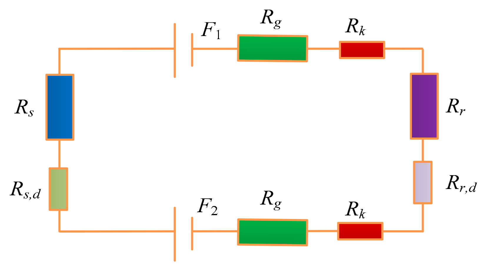
To analyze the influence of the eddy current effect on the canned MBs, the static magnetic flux density operating point is first determined using the nonlinear magnetic circuit modeling method proposed in Reference [21]. Subsequently, the effective magnetic reluctance approach is employed to evaluate the dynamic load-carrying capacity of the canned MBs under alternating magnetic fields. The magnetic circuit is simplified by considering a single representative magnetic path; the resulting simplified model is illustrated in Figure 2. Based on the pole area and air gap length, the air gap magnetic reluctance Rg of the canned MBs is calculated as
R g = g 0 μ 0 A g ,
where g0 denotes the air gap length, μ0 is the vacuum permeability, and Ag is the area of the equivalent magnetic circuit. Both the stator and rotor cores of the MBs are fabricated by laminating silicon steel sheets, and the corresponding magnetic reluctance Rg can be expressed as
R s = l s μ s A s ,   R r = l r μ r A r ,
where Rs and Rr denote the magnetic reluctance of the stator core and rotor core, respectively; ls and lr denote the equivalent magnetic circuit lengths of the stator core and rotor core, respectively; As and Ar denote the equivalent magnetic circuit areas of the stator core and rotor core, respectively; μs and μr denote the magnetic permeability of the stator core and rotor core, respectively.
The magnetic permeability characteristics of silicon steel sheets in alternating magnetic fields are characterized using frequency-dependent complex magnetic reluctance, and the dynamic relative permeability μf of silicon steel sheet materials can be expressed as [22]
μ f = μ tanh j 2 π f B σ μ μ 0 d 0 2 j 2 π f B σ μ μ 0 d 0 2 ,
where fB denotes the frequency of magnetic field variation; σ and μ denote the electrical conductivity and relative static permeability of silicon steel sheets, respectively; and d0 stands for the thickness of the silicon steel sheet. For the shielding sleeve made of solid materials, its equivalent magnetic reluctance Rk can be expressed as
R k = l k μ k A k + 1 2 π ln r a 4 r a 3 σ k s μ k ,
where lk denotes the equivalent magnetic circuit length of the shielding sleeve; Ak is the equivalent magnetic circuit area of the shielding sleeve; σk and μk denote the electrical conductivity and relative static permeability of the shielding sleeve, respectively; ra4 and ra3 denote the outer diameter and inner diameter of the shielding sleeve, respectively. Considering factors such as the saturation effect and eddy current effect comprehensively, the equivalent magnetic reluctance Rz of a single magnetic circuit of the canned MBs can be calculated as
R z = 2 R g + R s + R r + 2 R k + R s , d + R r , d ,
where Rs,d and Rr,d denote the equivalent dynamic magnetic reluctance of the stator and rotor, respectively. Based on the magnetomotive force F and the equivalent magnetic reluctance Rz, the air-gap magnetic flux density B of the canned MBs can be calculated as
B = F R z A g ,   F = F 1 + F 2 ,
where F1 and F2 denote the magnetomotive forces of the two magnetic poles, respectively.
The canned MBs employ differential control. Based on Maxwell’s stress tensor formula, the electromagnetic force f acting in a single control direction can be calculated as
f = B + 2 A g cos ψ μ 0 B 2 A g cos ψ μ 0 ,
where B+ and B denote the air-gap magnetic flux densities of the canned MBs along the two differential directions, respectively; ψ is the angle between the magnetic pole centerline and the reference centerline. By performing a Taylor expansion on the above formula, the approximate linear expression for the electromagnetic force is derived as
f = K r , x ( t ) x + K r , i ( t ) i c ,
K r , x ( t ) a b ,   K r , i ( t ) c d ,
where x denotes the rotor displacement at time t, and ic is the control current. Kr,x(t) is the current stiffness, while Kr,i(t) is the displacement stiffness. Owing to the eddy current effect, the stiffness of the canned MBs exhibits time-varying characteristics, where a and b are the upper and lower bounds of the current stiffness, and c and d are the upper and lower bounds of the displacement stiffness.

2.2. Dynamic Modeling

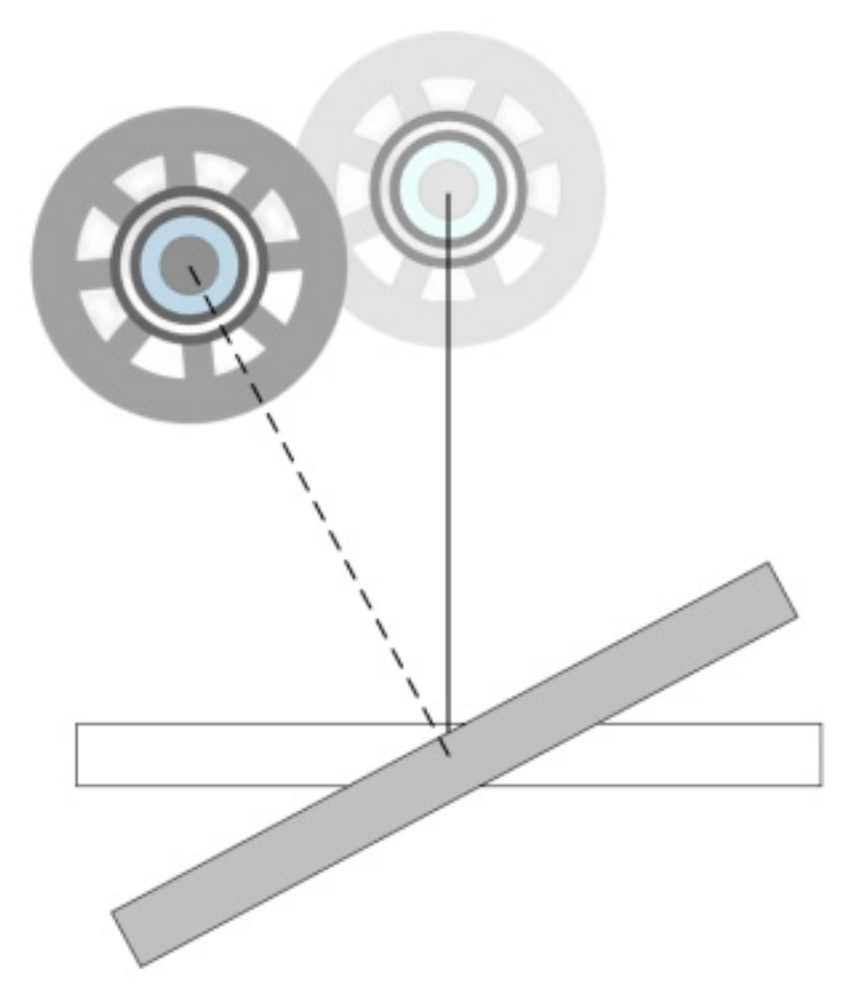
As illustrated in Figure 3, the canned MBs are mounted on the equipment via the stator and rigidly connected to the ship hull through the base. The swaying motion of the ship hull, induced by marine environmental excitations (e.g., waves and ocean currents), is transmitted to the canned MBs through the base, exerting a significant impact on the dynamic characteristics and stability of the canned MB system. These motions continuously inject dynamic disturbances into the canned MB-rotor system via the rigid connection of the base.
To simplify the analysis, considering the sway motion along a single attitude direction of the hull, the dynamic equation for the canned MB-rotor system under a single degree of freedom can be derived as
m x ¨ r = K r , x ( t ) x r + K r , i ( t ) i c + ξ ( x r ) ,
where m is the rotor mass, xr is the rotor displacement at time t, and ξ(xr) is the equivalent load induced by variations in the ship motion load. By reformulating the dynamic equation of the canned MBs system into a state—space form, the state equation of the system can be derived as follows:
x ˙ = A x + B u c + η x ,
where x denotes the state variable of the canned MBs, A and B denote the control matrices of the system, respectively, and η(x) is the unknown dynamic vector of the system.

3. Improved Model Reference Adaptive Control for Marine Canned MBs (MRAC)

To simultaneously mitigate the impacts of internal and external disturbances on marine canned MBs, the conventional model reference adaptive control (MRAC) algorithm is modified. Specifically, the reference model and adaptive law are optimized using tracking errors, thereby improving the control performance of the canned MBs.

3.1. Principle of MRAC

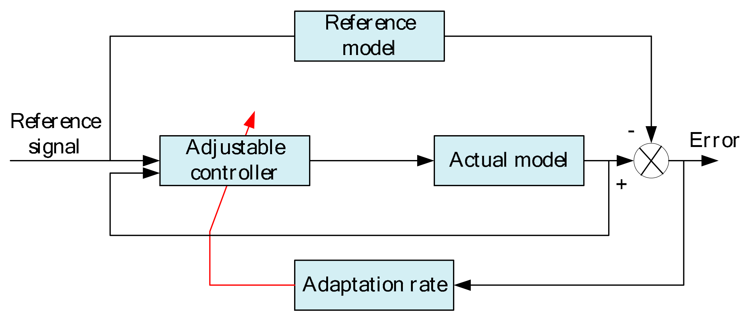
The principle of the typical MRAC is illustrated in Figure 4. Parameter perturbations of the controlled plant will lead to a mismatch between the dynamic characteristics of the actual system and the reference model, thereby inducing tracking errors. The adaptive law processes these errors to adjust the controller parameters in real time, generating control signals to compensate for variations in the characteristics of the actual controlled plant and ensuring that the output of the actual system tracks the reference model [23].

3.2. Design of Improved MRAC

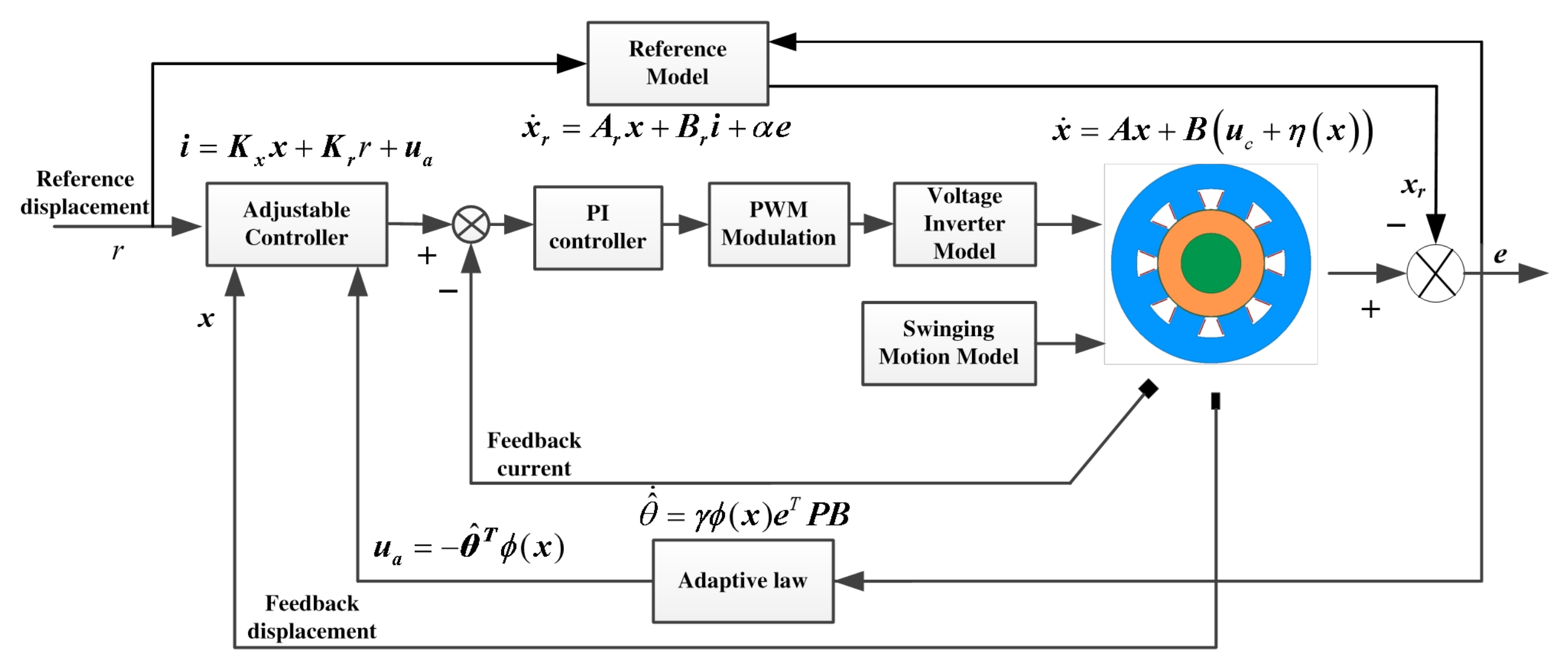
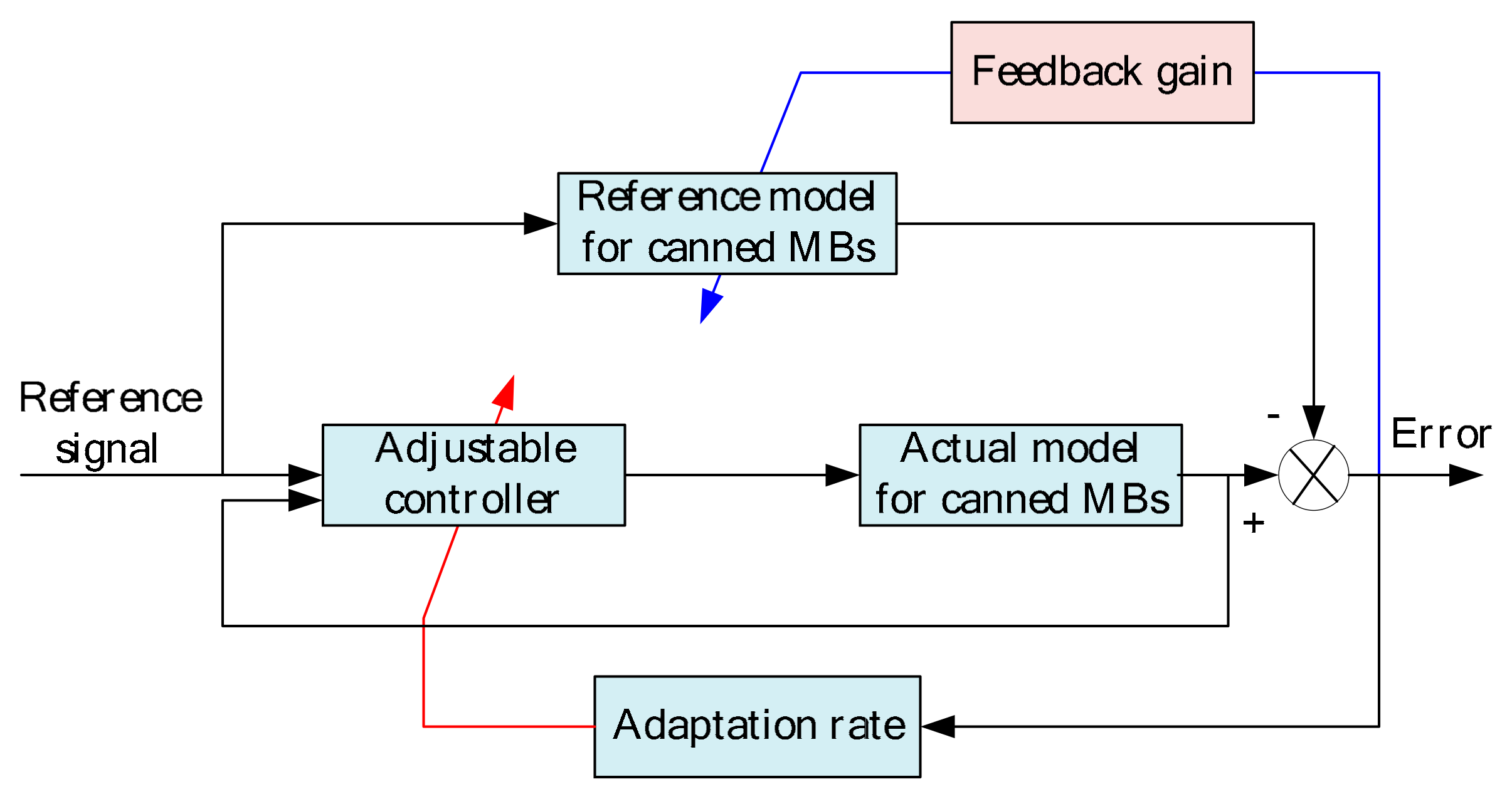
To simultaneously address the periodic load variations imposed on the canned MB-rotor system by ship rocking motion and the time-varying stiffness characteristics induced by strong eddy current effects, this paper proposes an improved Model Reference Adaptive Control (MRAC) algorithm. The algorithm’s workflow and principle are illustrated in Figure 5. To tackle both internal and external disturbances, the improved MRAC algorithm is improved from two perspectives: strengthening the robustness of the reference model and optimizing the adaptive law. On one hand, the improved MRAC algorithm directly feeds back the tracking error of the canned MBs system to the reference model. By fully leveraging error information, the control performance of the canned MBs is optimized. On the other hand, in the design of the adaptive law, not only is the output error utilized, but also the estimated internal state values of the canned MBs system are introduced to form a feedback loop, thereby enhancing the robustness of the canned MBs system. A model-based prediction error is incorporated into the adaptive update law as an additional feedback signal, constructing a more robust control parameter optimization mechanism. This mechanism can distinguish the impacts of internal and external parameter uncertainties of the canned MBs, compensate for uncertain disturbances, and achieve high-performance stable control of the canned MBs in complex environments.
Therefore, this paper adopts an indirect method to address these factors by uniformly representing the resulting modeling errors as unknown state variables, which are subsequently estimated using an observer. The unknown state quantity η(x) of the dynamic model for the actual canned MBs system can be characterized as follows:
η ( x ) = θ T ϕ ( x ) ,
where θ is an unknown constant parameter, and ϕ(x) is a bounded regression vector.
By integrating the dynamic model of the canned MBs, the reference model for the canned MBs under the improved MRAC algorithm is designed as follows:
x ˙ r = A r x + B r i + α e ,
e = x x r ,
where xr is the state variable of the reference model for the canned MBs, i is the specified control current, Ar is a Hurwitz matrix, Br is the input matrix, e is for the system tracking error between the actual model and the reference model of the canned MBs, and α is the feedback gain.
In light of the algorithmic principle, the controller input for the improved MRAC algorithm applied to the canned MBs is designed as follows:
i = K x x + K r r + u a ,
where r is the reference signal, Kx is the feedback gain, and Kr is for the feedforward gain; the two gains satisfy the following relationships, respectively:
A r = A + B K x ,
B r = B K r ,
The adaptive feedback term ua for the improved MRAC algorithm applied to the canned MBs is designed as follows:
u a = θ ^ T ϕ ( x ) ,
where θ ^ is the estimated value of the unknown system parameter θ; further, the adaptive law for the improved MRAC algorithm applied to the canned MBs is designed as follows:
θ ^ ˙ = γ ϕ ( x ) e T P B ,
θ ˜ = θ θ ^ ,
where θ ˜ is the estimation error of the unknown parameter θ, γ is the adaptive law gain, and P is a positive real symmetric matrix that satisfies the Lyapunov equation:
A r T P + P A r = Q ,
where Q is a positive real symmetric matrix.
Based on the aforementioned equations, the derivative of the system tracking error for the canned MBs under the improved MRAC algorithm is derived as
e ˙ = A r α I e + B θ ˜ T ϕ x ,
where I is the identity matrix.

3.3. Analysis of System Stability

To analyze the stability of the canned MBs system under the improved MRAC algorithm, a Lyapunov function V is first constructed as follows:
V = e T P e + t r θ ˜ T γ 1 θ ˜ ,
By differentiating the Lyapunov function, its derivative V ˙ can be obtained as
V ˙ = e ˙ T P e + e T P e ˙ + 2 t r θ ˜ T γ 1 θ ˜ ˙ ,
Synthesizing the aforementioned functions, the derivative of the Lyapunov function can be further simplified as
V ˙ = e ˙ T A r T P + P A e + 2 e T P B θ ˜ T ϕ 2 t r θ ˜ T ϕ e T P B 2 α e T P e ,
By virtue of the properties of the matrix trace, the following relationship can be derived.
t r θ ˜ T ϕ e T P B = t r e T P B θ ˜ T ϕ = e T P B θ ˜ T ϕ ,
Further simplifying (25), the following result can be derived:
V ˙ = e T Q e 2 α e T P e 0 ,
Thus, synthesizing the aforementioned derivations, it can be concluded that V ≥ 0 and V ˙ ≤ 0. In accordance with Lyapunov stability theory, the canned MBs system under the improved MRAC algorithm satisfies Lyapunov stability.

4. Validation of the Algorithm

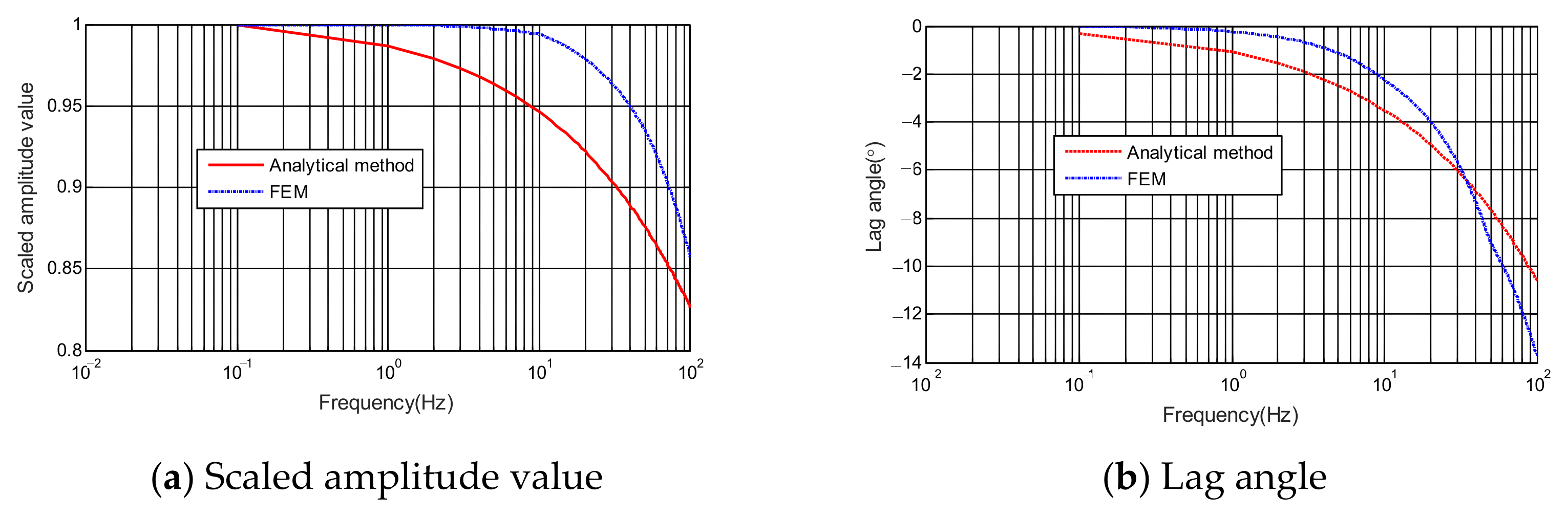
To validate the effectiveness of the improved MRAC algorithm, the electromagnetic forces of the canned MBs at different frequencies were first calculated by incorporating the canned MB parameters in Table 1 and accounting for eddy current and saturation effects. To further validate the accuracy of the electromagnetic force analysis model, the finite element model of the canned MBs is constructed using ANSYS 2022R1. Electromagnetic forces at different frequencies are calculated using both the analytical model and the finite element method (FEM); the scaled amplitude values and lag angles of the electromagnetic forces are illustrated in Figure 6. It can be observed that within the analyzed frequency range, the maximum error in electromagnetic force magnitude does not exceed 7%, and the maximum angular error does not exceed 4°.
From the results illustrated in Figure 6, it can be observed that as the frequency increases, the eddy current effect is exacerbated, leading to a corresponding increase in the amplitude attenuation and phase lag of the canned MBs. Within the investigated frequency response range, the dynamic maximum load capacity of the MBs decays to 86%, with the maximum phase lag reaching up to 13 degrees. A simulation model of the canned MBs system under ship motion was constructed using Simulink, and its control block diagram is illustrated in Figure 7. The key control parameters of the improved MRAC algorithm for the canned MBs system were configured, where K r = 1 , γ = 100 0 0 0 100 0 0 0 100 , α = 250 0 0 100 . The PID control parameters are tuned using the method described in Reference [3], with kp = 8 A/mm, ki = 100 A/(mm·s), kd = 0.15 A·s/mm. kp, ki and kd represent the proportional coefficient, integral coefficient, and derivative coefficient of the PID controller, respectively.
Figure 7. The block diagram for the improved MRAC algorithm of canned MBs.
Actuators 15 00129 g007

4.1. Ship Sway Motion Condition

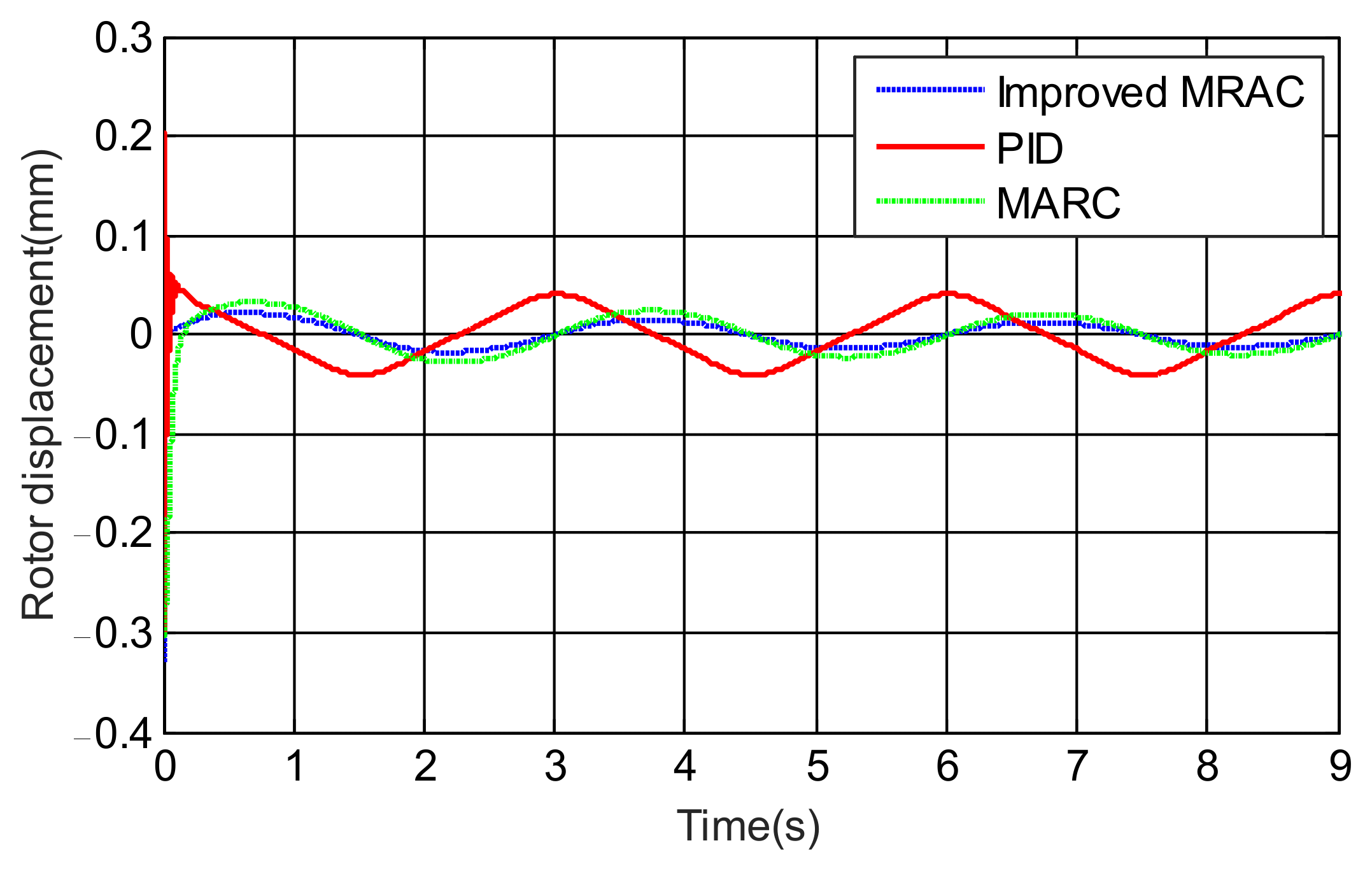
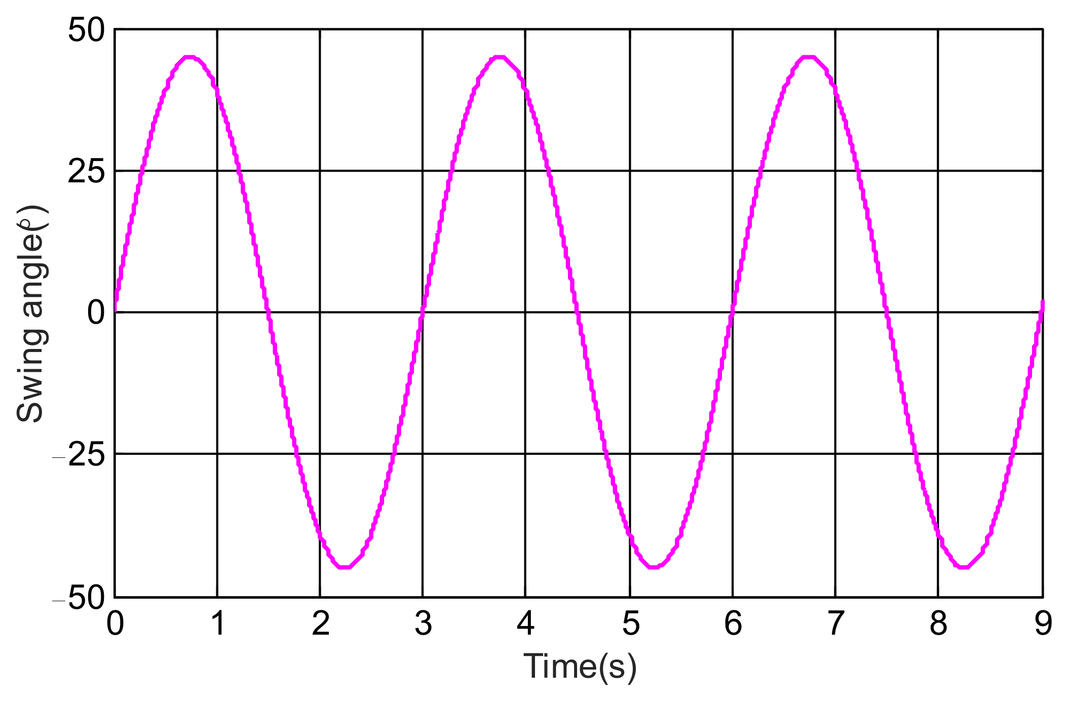
Considering ship sway motion and in compliance with national standard requirements, extreme assessment conditions were established: the maximum sway angle was set to 45 degrees, the sway period to 3 s, and the sway angle curve is illustrated in Figure 8. Using the simulation model, the rotor displacement curve of the canned MBs under ship sway motion conditions was calculated and compared with that of the traditional PID control algorithm; the results are presented in Figure 9, and the fundamental frequency displacement obtained through Fourier decomposition is shown in Table 2. The findings indicate that, relative to PID control, the rotor vibration of the canned MBs under the improved MRAC algorithm was reduced by 73.8%. However, due to the absence of an integral component, a static error exists in rotor vibration under the improved MRAC algorithm.

4.2. Variable Stiffness Condition

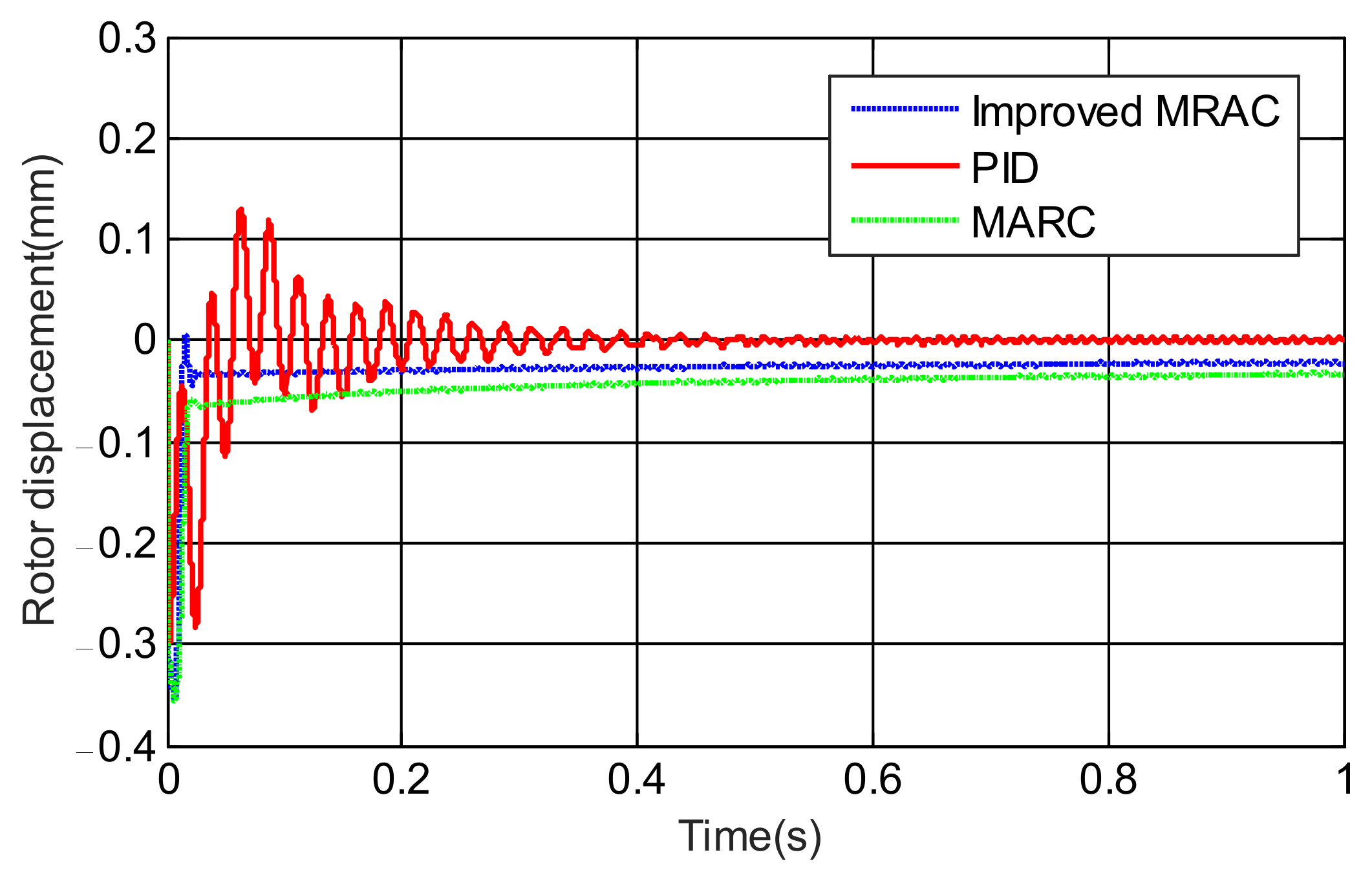
Considering the stiffness variation induced by strong eddy current effects, and accounting for the maximum amplitude attenuation and phase lag, with the stiffness variation range set from 0.86 to 1 times the static stiffness (352 N/A), a sinusoidal reference displacement signal was configured with a frequency of 100 Hz and an amplitude of 0.01 mm. Using the simulation model, the rotor displacement curve and control current of the canned MBs were calculated and compared with those obtained via the traditional PID control algorithm; the results are presented in Figure 10, the fundamental frequency displacement obtained through Fourier decomposition is shown in Table 3. It can be observed that, relative to PID control, the rotor vibration of the canned MBs under the improved MRAC algorithm is reduced by 53.7% under the variable stiffness condition.

5. Conclusions

To simultaneously tackle external sway disturbances and internal parameter perturbations induced by strong eddy current effects, this paper proposes an improved MRAC method for canned MBs. By enhancing the adaptability of MBs to both internal and external disturbances via state observation and predictive error feedback, the effectiveness of the algorithm is validated through simulations. The results indicate that, compared with PID control, the rotor vibration under ship sway motion conditions is reduced by 73.8% and by 53.7% under variable stiffness conditions with the improved MRAC algorithm. Future work will focus on conducting research on the improved MRAC for multi-degree-of-freedom MBs and verifying the algorithm experimentally using a prototype.

Author Contributions

Conceptualization, J.P.; Data curation, H.J.; Funding acquisition, H.J.; Investigation, J.P.; Methodology, H.J.; Software, H.J. and Y.L.; Validation, H.J. and Z.S.; Writing—original draft, J.P.; Writing—review and editing, J.P. and Q.L. All authors have read and agreed to the published version of the manuscript.

Funding

Hubei Provincial Natural Science Foundation of China under Grant 2024AFB340.

Data Availability Statement

The data presented in this study are available on request from the corresponding author. The data are not publicly available due to the privacy agreement among co-authors.

Conflicts of Interest

The authors declare no conflicts of interest.

References

  1. Wang, X.F.; Liu, F.; Wang, N.N. Review of Development in Green Ship Propulsion Technology. Ship Eng. 2025, 47, 412–417. [Google Scholar]
  2. Lu, M.J.; Dong, S.J.; Tang, M.; Wang, C.R.; Cao, L.; Yan, X.P. Research on the Development of China’s Marine Transportation Equipment Industry. Strategy Study CAE 2023, 25, 53–61. [Google Scholar] [CrossRef] [Scilit]
  3. Huang, L.; Chen, X.X.; Li, X.N.; Zhang, W.Z.; Wang, X.Q.; Huang, M. Development Status of Turbocharging Technology for Marine Diesel Engines. J. Propuls. Technol. 2020, 41, 2438–2449. [Google Scholar]
  4. Wei, Y.S.; Cheng, G.; Wang, D.; Jin, S.B.; Wu, X.Y. Generation Mechanism and Suppression of Flow-Induced Resonance in Blades of Shaftless Pump-Jet. J. Harbin Eng. Univ. 2024, 45, 375–382. [Google Scholar]
  5. Wang, D.; Jiang, H.; Su, Z.Z.; Wu, C. Review of Key Technologies and Development of Marine Magnetic Levitation Bearings. Proc. CSEE 2020, 40, 6704–6715. [Google Scholar]
  6. Wang, X.L.; Wu, H.C.; Wang, W.Y.; Yang, T.S. Vibration Characteristics of Marine Magnetic Levitation Equipment under Base Pitching Excitation. Bearing 2025, 8, 8–13. [Google Scholar]
  7. Han, B.C.; Cui, B.W.; Zheng, S.Q.; Zhang, Y.; Song, X.D. Pressure Regulation Model and Experiment for Clearance of Magnetic Levitation Compressor. J. Vib. Meas. Diagn. 2019, 39, 286–291. [Google Scholar]
  8. Liu, G.; Zhu, H.Q. Review of Magnetic Bearings for Flywheel Energy Storage. Bearing 2024, 1, 9–18. [Google Scholar]
  9. Zhang, K.; Dai, X.J.; Zhang, X.Z.; Wu, H.; Zou, M.; Li, Q.Z. Vibration Suppression of Magnetic Levitation Molecular Pump. J. Vac. Sci. Technol. 2013, 33, 556–562. [Google Scholar]
  10. Liu, N.Q.; Xiang, X.W.; Chen, Z.; Li, H.; Jiang, P. Modeling and Performance Analysis of Main Pump Motor Considering Shield Failure. Trans. China Electrotech. Soc. 2024, 39, 25–36. [Google Scholar]
  11. Jiang, H.; Su, Z.Z.; Wang, D. Dynamic Modeling of Magnetic Bearing-Rotor System on Moving Platform. Trans. China Electrotech. Soc. 2019, 34, 4880–4889. [Google Scholar]
  12. Su, Z.Z.; Jiang, H.; Liu, Q.; Wu, C.; Li, Z. Design and Verification of Shielded Electromagnetic Bearing for Pumps. In Proceedings of the Abstracts of the 11th National Conference on Magnetic Levitation Technology and Vibration Control, Changsha, China, 4–7 August 2023. [Google Scholar]
  13. Cole, M.O.T.; Fakkaew, W. An Active Magnetic Bearing for Thin-Walled Rotors: Vibrational Dynamics and Stabilizing Control. IEEE/ASME Trans. Mechatron. 2018, 23, 2859–2869. [Google Scholar] [CrossRef] [Scilit]
  14. Zhou, L.; Li, L. Modeling and Identification of a Solid-Core Active Magnetic Bearing Including Eddy Currents. IEEE/ASME Trans. Mechatron. 2016, 21, 2784–2792. [Google Scholar] [CrossRef] [Scilit]
  15. Kang, M.S.; Lyou, J.; Lee, J.K. Sliding Mode Control for an Active Magnetic Bearing System Subject to Base Motion. Mechatronics 2010, 20, 171–178. [Google Scholar] [CrossRef] [Scilit]
  16. Soni, T.; Dutt, J.K.; Das, A.S. Parametric Stability Analysis of Active Magnetic Bearing Supported Rotor System with a Novel Control Law Subject to Periodic Base Motion. IEEE Trans. Ind. Electron. 2019, 67, 1160–1170. [Google Scholar] [CrossRef] [Scilit]
  17. Zhang, Y.; Xu, Y.; Zhou, J.; Zhou, Y.; Mahfoud, J. Vibration Control of AMB-Rotor System under Base Motions Based on Disturbance Observer. IEEE/ASME Trans. Mechatron. 2025, 30, 5398–5407. [Google Scholar] [CrossRef] [Scilit]
  18. Wu, H.; Zhang, L.; Zhou, J.; Hu, Y. Dynamic Analysis and Vibration Control of a Rotor-Active Magnetic Bearings System with Base Motion. J. Vib. Control. 2024, 30, 2697–2708. [Google Scholar] [CrossRef] [Scilit]
  19. Chen, W.; Zhuang, G.; Gao, F.; Liu, W.; Xia, W. H∞ control for singular systems with interval time-varying delays via dynamic feedback controller. J. Frankl. Inst. 2023, 360, 1106–1123. [Google Scholar] [CrossRef] [Scilit]
  20. Li, X.; Li, S. Speed control for a PMSM servo system using model reference adaptive control and an extended state observer. J. Power Electron. 2014, 14, 549–563. [Google Scholar] [CrossRef] [Scilit]
  21. Jiang, H.; Su, Z.Z.; Wang, D. Analytical Calculation of Active Magnetic Bearing Based on Distributed Magnetic Circuit Method. IEEE Trans. Energy Convers. 2021, 36, 1841–1851. [Google Scholar] [CrossRef] [Scilit]
  22. Le, Y.; Wang, K. Design and Optimization Method of Magnetic Bearing for High-Speed Motor Considering Eddy Current Effects. IEEE/ASME Trans. Mechatron. 2016, 21, 2061–2072. [Google Scholar] [CrossRef] [Scilit]
  23. Datta, A.; Ioannou, P.A. Performance Analysis and Improvement in Model Reference Adaptive Control. IEEE Trans. Autom. Control. 2002, 39, 2370–2387. [Google Scholar] [CrossRef] [Scilit]
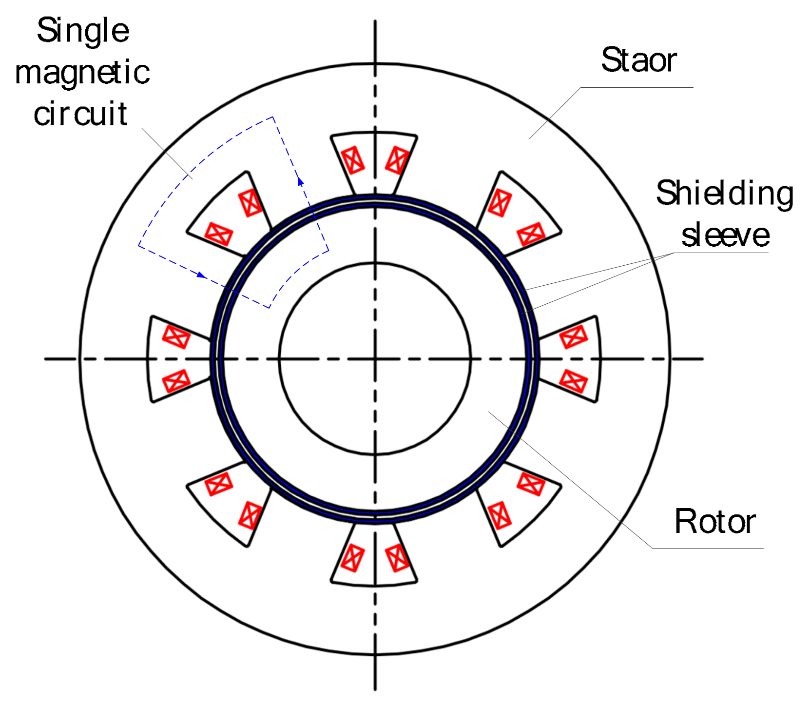
Figure 1. Structure of canned MBs.
Actuators 15 00129 g001
Figure 2. Equivalent magnetic circuit model.
Actuators 15 00129 g002
Figure 3. Motion relationship between marine MBs and their bases.
Actuators 15 00129 g003
Figure 4. Principles of adaptive control based on typical model references.
Actuators 15 00129 g004
Figure 5. Improved MRAC algorithm process for canned MBs.
Actuators 15 00129 g005
Figure 6. Electromagnetic forces in canned MBs at different frequencies.
Actuators 15 00129 g006
Figure 8. Curve of swing angle.
Actuators 15 00129 g008
Figure 9. Curve of rotor displacement under ship sway motion condition.
Actuators 15 00129 g009
Figure 10. Curve of rotor displacement under variable stiffness conditions.
Actuators 15 00129 g010
Table 1. Key Parameters of canned MBs.
ParametersValueGrade or Unit
statorsilicon steel sheet35WW270
rotorsilicon steel sheet35WW270
shielding sleeveHastelloy alloy-
electromagnetic air gap1.5mm
rotate speed3000rpm
stator outer diameter312mm
bias magnetic flux density0.8T
Table 2. Fundamental frequency displacement of rotors under ship sway motion condition with different control methods.
Control MethodsRotor Displacement (Fundamental Frequency)Unit
Improved MRAC0.0123mm
PID0.0375mm
MRAC0.0199mm
Table 3. Fundamental frequency displacement of rotors under variable stiffness conditions with different control methods.
Control MethodsRotor Displacement (Fundamental Frequency)Unit
Improved MRAC0.001543mm
PID0.003807mm
MRAC0.001562mm
Disclaimer/Publisher’s Note: The statements, opinions and data contained in all publications are solely those of the individual author(s) and contributor(s) and not of MDPI and/or the editor(s). MDPI and/or the editor(s) disclaim responsibility for any injury to people or property resulting from any ideas, methods, instructions or products referred to in the content.