1. Introduction
In recent years, the global population has been aging, and the working population has been declining, raising concerns about a shortage of labor in physically demanding tasks such as agricultural work [
1]. In particular, agricultural tasks often require workers to remain in squatting or half-squatting postures for extended periods, which can lead to lower back pain due to sustained muscle tension in the lumbar region [
2,
3,
4,
5,
6]. This is because many agricultural tasks, such as planting, harvesting, weeding, and lifting or transporting crops, are performed near ground level in environments where full automation is difficult, resulting in frequent strain on the lower back. Such physical burdens pose a serious issue for workers [
7,
8], and addressing these problems is essential for ensuring their ability to lead healthy lives.
One approach to addressing this issue is the use of back-support exoskeletons (assistive suits) [
9,
10,
11,
12]. These devices are expected to be lightweight and to assist human movements promptly and comfortably. In past research and development efforts, various types of back-support exoskeletons have been proposed, including active types that use electric motors and sensors, passive types that utilize elastic elements, and structural designs ranging from those composed of rigid frames to those made of soft, flexible materials. These have been well summarized in several review papers [
13,
14,
15].
Among the various types of back-support exoskeletons, this paper focuses on rigid-frame designs, which are considered particularly promising due to their potential to provide relatively large assistive forces and, consequently, more effective support. Rigid-frame exoskeletons can be broadly classified into active and passive types, depending on the actuation method employed.
Active systems typically comprise sensors, an onboard computer, actuators, and a battery to power the entire unit. While these systems offer the advantage of allowing the flexible configuration of assistive force profiles—enabling potentially high assistive performance—they are often limited by increased weights and restricted operating times. Moreover, the system’s performance is highly dependent on the capabilities of each individual hardware component, and overall costs tend to rise with system complexity and performance level [
16,
17,
18].
Passive types generate assistive force through elastic elements such as rubber belts, springs, gas springs, and pneumatic artificial muscles (PAMs) and therefore generally do not require sensors, computers, or batteries. As a result, they are lightweight, have no limitations on operating time, and offer advantages in terms of system simplicity and cost-effectiveness. These characteristics make passive exoskeletons well suited for real-world applications and suggest strong potential for widespread adoption. However, many of these devices employ mechanisms in which the elastic elements stretch in response to the user’s squatting posture angle, resulting in a corresponding increase in assistive force. Due to the limited flexibility in adjusting assistive force, it is generally difficult to achieve highly effective assistance based on advanced assistive strategies [
19,
20,
21].
Despite the development of various back-support exoskeletons, they have not yet been widely adopted in actual working environments [
13]. For active systems, the primary limiting factors are considered to be their weight, limited operating time, and high cost. In the case of passive systems, a major issue is the lack of flexibility in tuning the assistive force profiles. For example, minimal assistance is provided near the standing posture whereas excessive assistive force may be applied when the user bends forward deeply, which can hinder the ability to reach the ground with the hands and ultimately reduce task efficiency.
Furthermore, in research on back-support exoskeletons, there is a lack of studies that evaluate the assistive effects in torso-twisting postures, such as semi-squatting posture with a staggered stance, which are frequently observed in agricultural work. As such, the effectiveness of these devices in agricultural settings remains unclear.
In this paper, we focus on two key aspects to evaluate the assistive performance of our proposed back-support exoskeleton. The first is the mechanical adjustment of assistive force profiles in a passive-type system. The second is its application to semi-squatting postures with a staggered stance, representative of actual agricultural work conditions. For this purpose, we utilize a passive-type back-support exoskeleton under development, which uses pneumatic artificial muscles (PAMs) and is referred to as SAEx in this paper. By adjusting the assistive force profiles according to the proposed method and conducting validation experiments under semi-squatting postures with a staggered stance, we assess the potential utility of the proposed SAEx in agricultural work.
2. Overview of SAEx
2.1. SAEx
Figure 1 shows the SAEx used in this study, which is currently under development in our laboratory. The SAEx is designed to support the upper body in a half-squatting posture, aiming to reduce the load on the intervertebral discs and erector spinae muscles caused by the upper body weight.
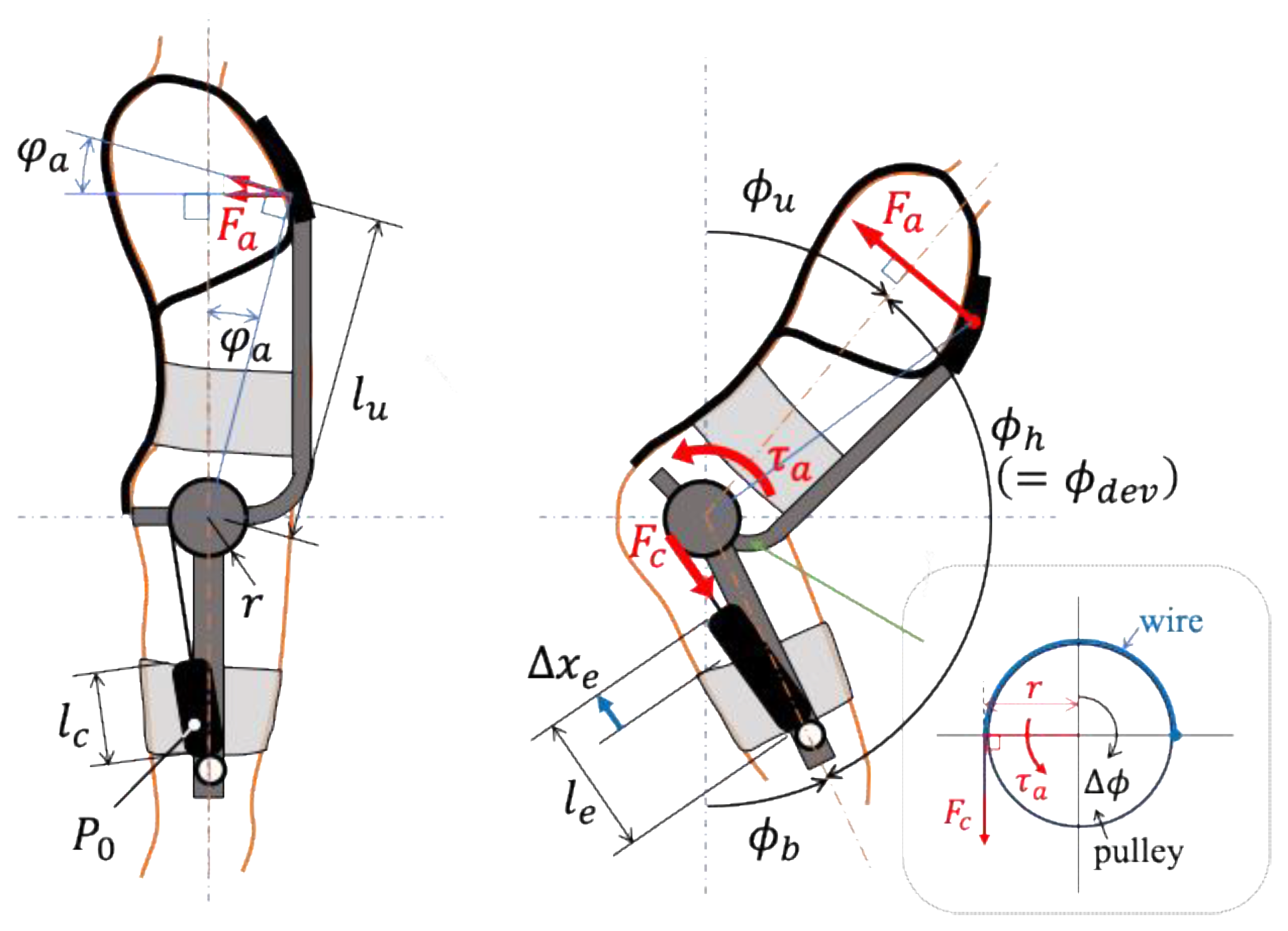
Figure 2 illustrates the operating principle of the assistive force mechanism in the SAEx. This mechanism consists of a shoulder belt, shoulder pad, back belt, body-fixed pad, lower limb pad (both pads are interconnected), upper body frame, lower limb frame, pulley, mechanism base, pneumatic artificial muscles (PAMs), and wires. The mechanism base is attached to the body-fixed pad. The lower limb frame extends downward from the base and is secured to the thigh via the lower limb pad. One end of the PAM is fixed near the knee on the lower limb frame. A pulley, to which the upper body frame is mounted, is installed on the mechanism base and is free to rotate. A wire connects this pulley to the tip of the PAM. The body-fixed pad is positioned so that the center of rotation of the pulley aligns with the user’s hip joint.
During use, the PAM is inflated to an appropriate pressure and sealed. In the standing posture, the PAM is at its shortest length due to maximum contraction. As the user transitions from standing to a half-squatting posture, the rotation angle of the pulley changes, causing the PAM to stretch. Because of the compressibility of air, the PAM behaves like a tension spring, generating a contractile force proportional to its extension. This force is transmitted via the wire to the upper body frame and acts in the upward direction near the user’s armpit, as shown in
Figure 2. As a result, the upper body is supported, and activity in the erector spinae muscles is reduced.
Many passive-type back-support exoskeletons incorporate elastic elements such as rubber belts and springs along the back, which contract to provide assistive force in the direction of standing [
22]. This approach mimics the function of the human erector spinae muscles by applying force along the dorsal side of the spine to support an upright posture. However, because this method applies compressive force to the lumbar vertebrae and intervertebral discs, it increases disc pressure, potentially leading to lower back pain, and is therefore not considered an ideal assistive strategy [
15,
23,
24]. To address this, the SAEx employs a different approach: it supports the upper body by applying force from the front in the standing direction, thereby minimizing compression on the intervertebral discs.
In addition, the SAEx features independent assistive mechanisms on the left and right sides of the body, allowing it to provide support even in a half-squatting posture with a staggered stance, as illustrated in
Figure 3. Although such twisted torso postures are not ergonomically ideal, they are frequently encountered in agricultural and similar manual labor tasks. This paper evaluates the assistive effectiveness of the SAEx in such postures.
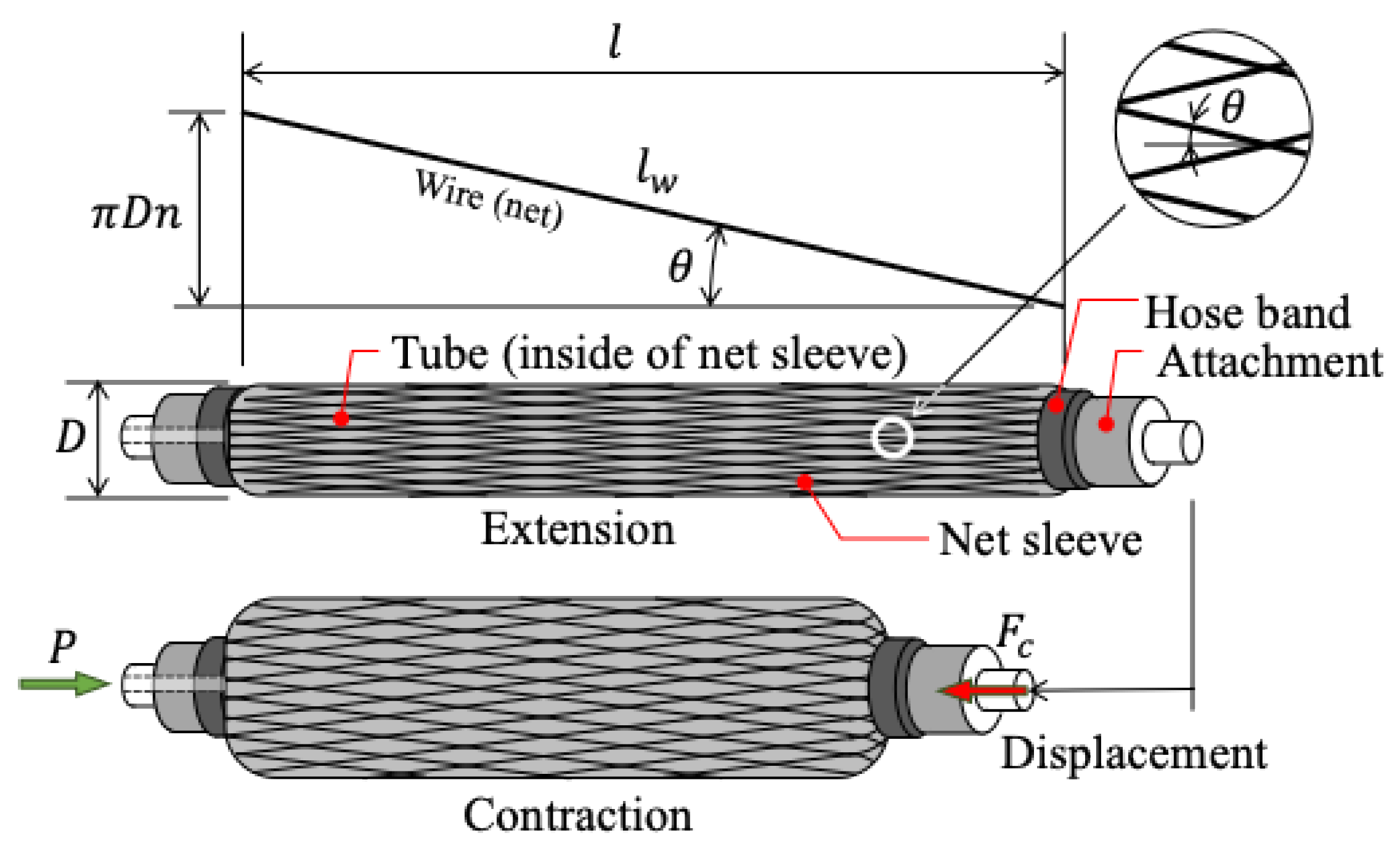
2.2. Pneumatic Artificial Muscle (PAM)
We summarize, here, the characteristics of the pneumatic artificial muscle (PAM) used in the SAEx. The SAEx employs a McKibben-type pneumatic artificial muscle whose contractile force is known to vary depending on the contraction ratio (i.e., the normalized contraction displacement relative to its natural length) and the internal pressure. A widely used model describing this behavior was proposed by Schulte [
25].
Figure 4 illustrates the geometric configuration of a single wire from the braided mesh sleeve that encases the McKibben PAM.
Let
denote the wire length,
the number of turns of the wire, and
the mesh angle of the sleeve. Then, the relationship between contractile force
, internal pressure
, length
, and diameter
of the PAM can be expressed by the following equations:
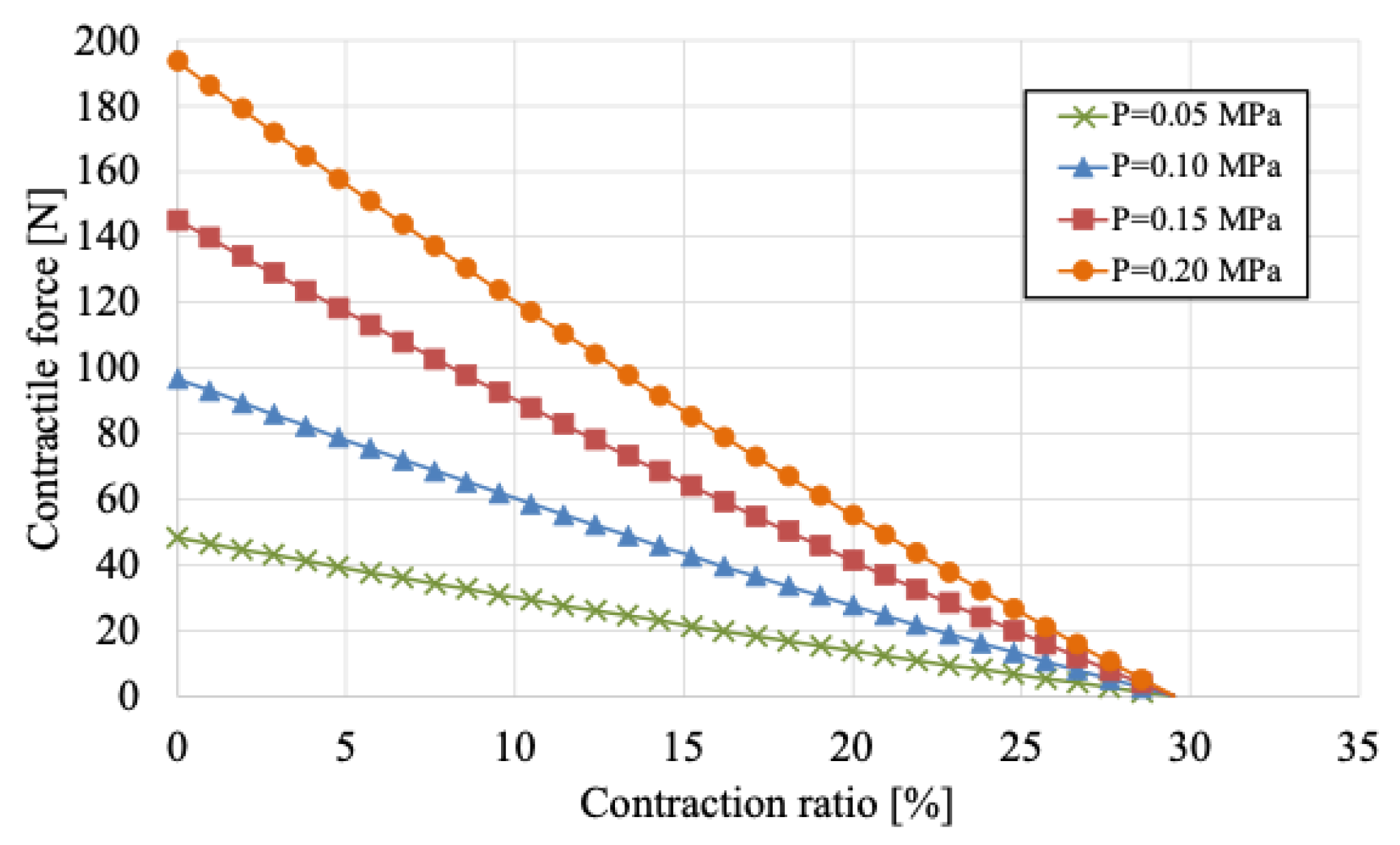
Based on these model equations, the isometric contraction characteristics—representing the relationship between contraction ratio and contractile force at various internal pressures—were calculated and are shown in
Figure 5. As illustrated, the maximum contraction ratio was approximately 30%, and the contractile force tended to decrease as the contraction ratio increased. Conversely, higher internal pressure resulted in greater contractile force. Therefore, the design has to take into account both the contraction ratio and the range of motion angles associated with the SAEx.
2.3. Assistive Force Depending on a Squatting Position
When the user bends at the waist and the hip joint angle
changes, the PAM stretches around the pulley located near the hip joint. This generates torque around the pulley, which in turn applies an assistive force
to the upper body. The assistive force
varies depending on the contractile force
, which is determined by the extent of PAM stretch. As such, the relationship between the hip joint angle and the assistive force is governed by the system’s mechanical configuration. In this paper, we modify this relationship to achieve a more effective assistive force, as suggested in [
26,
27], and evaluate its effectiveness. To do so, we analytically derive the relationship between the body flexion angle—closely associated with the hip joint angle—and the assistive force
.
First, we define the body flexion angle. As illustrated in
Figure 2, let
be the upper body flexion angle,
be the lower body flexion angle, and
be the hip joint angle. From a standing to a half-squatting posture, both
and
increase. We define the total body flexion angle
as follows:
Next, we describe the PAM extension
and the internal pressure
. From the standing position (initial condition), an arbitrary initial pressure
is applied, and the PAM is sealed. The PAM contracts to a length
, and assuming its volume
is approximately cylindrical, the volume can be expressed using Equations (2) and (3) as follows:
As the user leans forward from the standing position, the PAM is stretched by
via the SAEx pulley and its attached wire, resulting in an internal pressure
, a new length
, and volume
. The extension
and stretched length
are given thus:
Thus, the PAM length varies with the body flexion angle
. The volume
can be similarly calculated using Equation (5):
According to Boyle’s Law, the internal pressure
during stretching is given thus:
The corresponding contractile force
can be calculated using Equation (1) as follows:
This contractional force
generates a torque
around the hip joint pulley:
To relate this torque to the assistive force
, we consider the geometry shown in
Figure 2. Let
be the distance from the pulley’s rotation center to the upper body contact point and let
be the angle between this line and the vertical body axis. Then, the following holds:
Solving for
yields the following:
From Equation (14), it is evident that the assistive force is proportional to the contractile force of the PAM, as well as to the pulley radius .
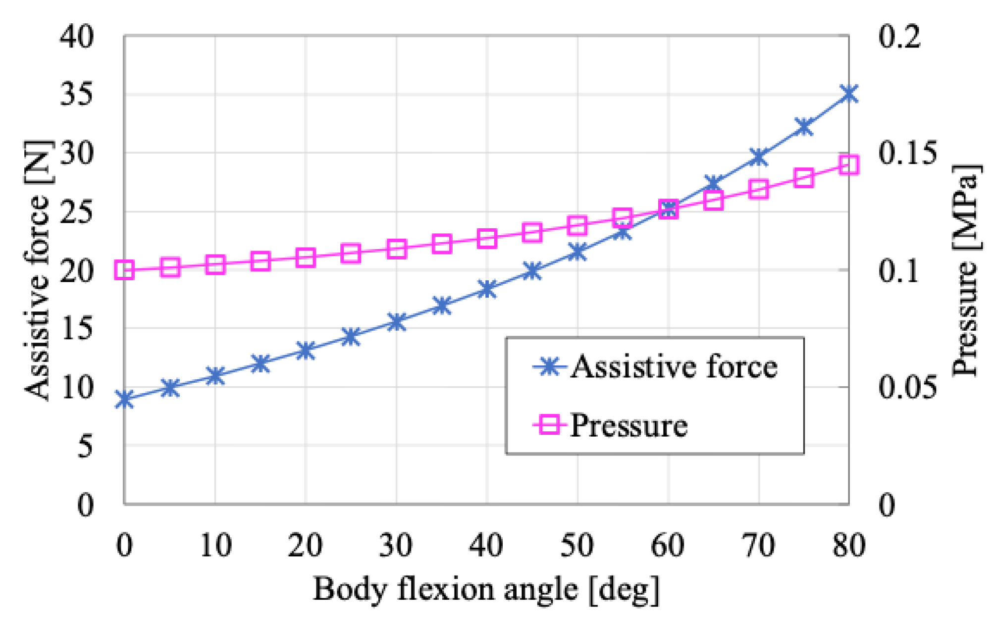
Figure 6 shows the relationship between the body flexion angle
, assistive force
, and the internal pressure
based on the parameter values listed in
Table 1.
Based on these results, the assistive force is minimal when the body flexion angle is close to 0° (i.e., near the standing posture), and it gradually increases as the user transitions to a more forward-leaning posture. This indicates that when wearing the SAEx, little assistive force is generated during tasks performed in or near the upright position, whereas the assistive force becomes more pronounced during tasks closer to the ground.
The magnitude of the assistive force near the standing posture is influenced by the initial internal pressure , and increasing can enhance the assistive effect in that range. However, the qualitative relationship between body flexion angle and assistive force remains unchanged. Therefore, increasing to improve assistance near the standing posture may result in excessive assistive force in deeper flexion postures (e.g., half-squatting), potentially hindering the user’s ability to reach the ground.
Additionally, as the body flexion angle increases, the internal pressure of the PAM also rises from the initial value of 0.1 MPa to approximately 0.15 MPa. Considering the pressure tolerance of the PAM, an excessive initial pressure is not desirable.
Accordingly, it is preferable for the assistive force to remain moderately active across a wide range of postures—from standing to half-squatting—without being excessively strong in either position.
3. Design of the Assistive Force Profile
As discussed in the previous section, it is desirable for the assistive force to be sufficiently high in the standing posture and to vary only moderately as the body flexion angle increases. To achieve this, the present paper proposes the use of a cam mechanism to tune the assistive force profile based on the body flexion angle.
The relationship between the contractile force
of the PAM and the assistive force
is given by Equation (14). When a pulley with constant radius
is employed, the assistive force
follows the same qualitative trend as the contractile force
. As shown in
Figure 6, the assistive force is relatively low in the standing posture and increases with deeper flexion, indicating that
exhibits a similar pattern.
To achieve an assistive force profile more suitable for semi-squatting tasks, it is necessary to vary the radius parameter
in Equation (14) according to the user’s body flexion angle
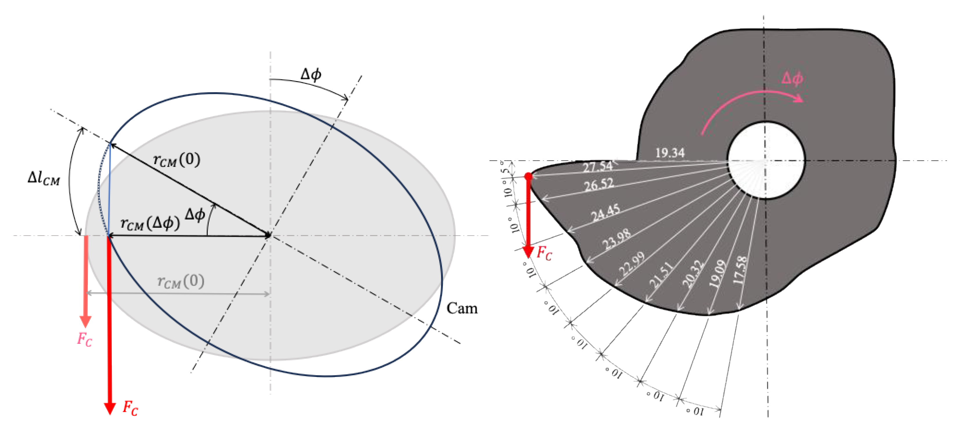
. This can be accomplished using a cam mechanism. As illustrated on the left side of
Figure 7, the distance from the center of the cam to the point of application of the PAM’s contractile force is defined as
.
Because the contractile force
depends on the stretch length
of the PAM, the corresponding extension must be calculated from the cam geometry. Before rotation, the distance is
; after rotation, it becomes
. Assuming that the angular displacement
is small and approximating the extension path as a straight line, the stretch length
can be computed using the law of cosines:
Using this expression, the contractile force
can be estimated. Although the direction of
may slightly deviate due to changes in
, it is assumed that the PAM is positioned sufficiently far from the cam such that the direction of force remains approximately vertical, as depicted in
Figure 7 (left). Incorporating this into Equation (14), the assistive force
generated by the cam is expressed as follows:
The cam radius was designed according to the following procedure:
Define the target assistive force as a function of .
Confirm that the desired profile requires a gradually decreasing radius .
Test several candidate functions to model ; in this case, a linear function was adopted.
Calculate the corresponding PAM extension and contractile force based on and internal pressure , then compute the resulting using Equation (16).
Plot the resulting assistive force profile and assess whether it meets the desired criteria.
Repeat steps 3 to 5 iteratively until the final satisfying the design requirements is obtained.
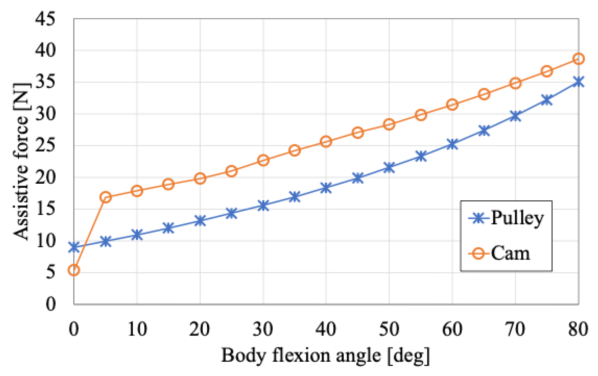
The cam geometry derived from this procedure is shown on the right side of
Figure 7 while the resulting assistive force profile is presented in
Figure 8. In
Figure 7 (right), the radius
corresponding to each rotational angle
is also indicated.
These results indicate that at a body flexion angle of = 80, the assistive force is approximately the same for both the cam and pulley mechanisms. However, at = 5°, the assistive force generated by the cam reaches approximately 17 N, which is about 70% higher than that of the pulley. Furthermore, as the flexion angle increases, the assistive force increases more gradually with the cam mechanism compared to the pulley, demonstrating a more desirable assistive force profile. The effectiveness of the assistive force profile achieved using the cam mechanism will be experimentally validated in the following section.
4. Experimental Method
In this paper, we experimentally evaluate the assistive effect of SAEx in a semi-squatting posture with a staggered (front–back leg) stance. Specifically, we assess the effectiveness of modifying the assistive force profile using a cam mechanism in comparison with a conventional pulley.
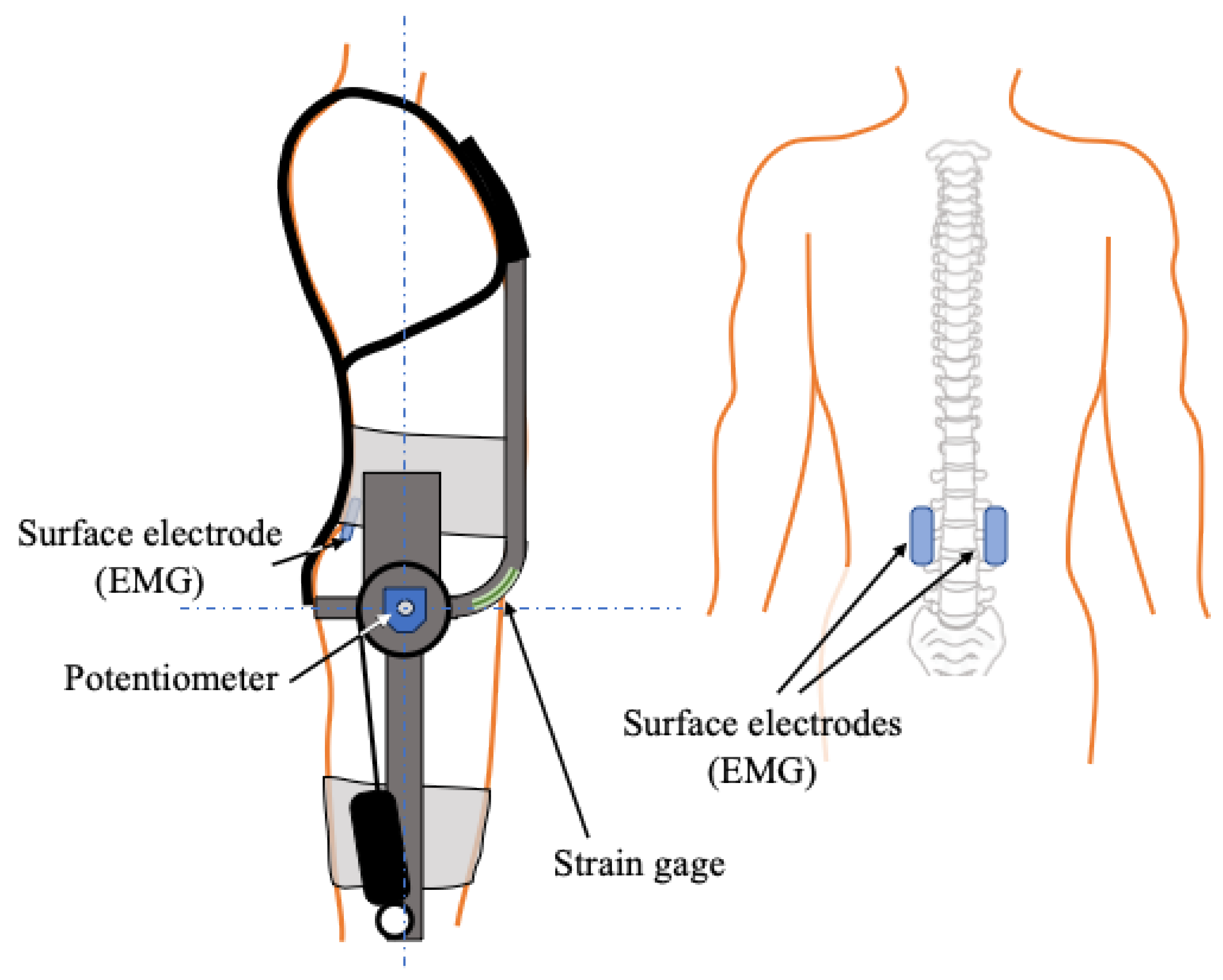
To obtain experimental data, as illustrated in
Figure 9, a potentiometer (RDC503; Alps Alpine) was attached to the SAEx to measure the hip joint angle
, and a strain gauge (KFGS-5-120; Kyowa, Tokyo, Japan) was mounted on the upper body frame to measure the assistive force
. The assistive force was calculated based on the measured strain and the geometric relationship between the pulley and the frame tip positions. The assistive effect was evaluated by analyzing the muscle activity of the erector spinae. The root mean square (RMS) values of the electromyographic (EMG) signals from the left and right erector spinae muscles (located along the spine), measured using surface EMG electrodes (Grove-EMG Detector; Seeed Studio, Shenzhen, China), were normalized by the maximum EMG values recorded during unassisted tasks, referred to as the pseudo-maximum voluntary contraction.
It should be noted that experimental results may exhibit asymmetry between the left and right sides due to individual anatomical differences, electrode signal variability, and the inherent asymmetry of the staggered stance. To minimize these effects, the muscle activity of each side was normalized independently, and the relative muscle activation was evaluated by comparison with the unassisted condition.
In this study, we conducted an experiment simulating actual agricultural work in a laboratory environment. The subject was instructed to carry two objects, each weighing 8.75 kg—representing harvested produce—into a container. The experimental setup is shown in
Figure 10. The task began with the subject grasping the front object while assuming a semi-squatting posture with a staggered stance. The subject then slightly stood up, moved to the container, and placed the object inside while maintaining the same posture. Subsequently, the subject retrieved the rear object and repeated the process. In both instances, the subject positioned the same leg forward during the semi-squatting stance.
As a result, the subject assumed the semi-squatting posture four times during each trial. Five trials were conducted for both the pulley and cam conditions, with the forward leg alternated between the left and right sides. This yielded a total of 20 semi-squatting postures per condition. For analysis, data from 16 of these postures—representative of the typical qualitative and quantitative muscle activity patterns—were used to evaluate the assistive effect.
5. Experimental Result and Discussion
First,
Figure 11 presents a comparison between the designed and actual assistive force output when using the cam mechanism in SAEx. The results confirmed that the assistive force
closely followed the intended design. Additionally, the influence of approximations used in the force calculation was found to be minimal.
Next, the experimental results for body flexion angle and erector spinae muscle activity during simulated agricultural work are presented.
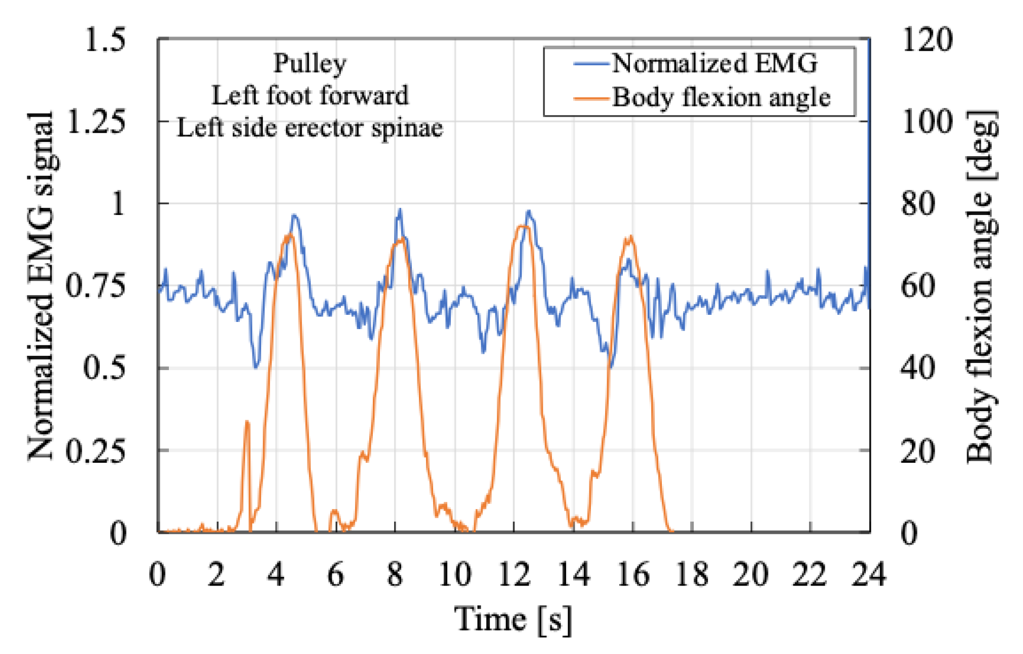
Figure 12 and
Figure 13 show the myoelectric activity of the left erector spinae muscle when the subject assumed a semi-squatting posture with the left foot forward. Compared with
Figure 14 and
Figure 15, the trunk flexion angle was observed to be greater on the left side. As shown in
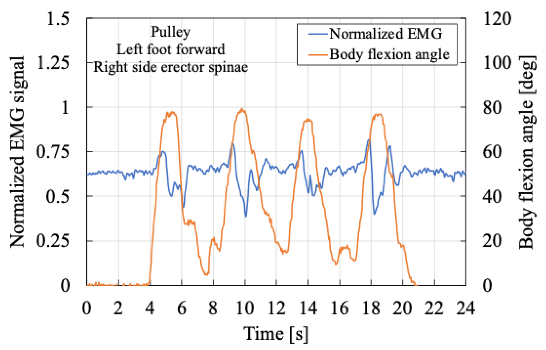
Figure 12, as the body flexion angle increased during the transition from a standing to a semi-squatting posture, muscle activity initially decreased before increasing again. This suggests a momentary relaxation of the erector spinae muscle during posture adjustment. Subsequently, the body flexion angle reached a local maximum, and the semi-squatting position was maintained. The subsequent increase in muscle activity was likely due to the need to stabilize the upper body following the transition.
These findings indicate that during the transition from standing to semi-squatting, a temporary decrease in muscle activity can occasionally occur.
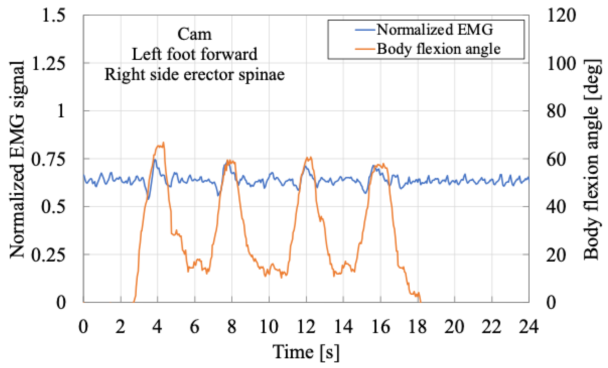
In contrast,
Figure 13 exhibits a different pattern. During the same posture transition, muscle activity did not decrease but instead increased continuously from the initial state. After reaching the semi-squatting position, muscle activity decreased during the transition back to standing. This may be attributed to an inertial effect wherein the upper body accelerated upward during the standing motion, reducing the activation of the erector spinae muscles. These results suggest that when the upper body is twisted, as in a staggered stance, the muscle activation patterns may differ between the left and right sides, even during the same movement.
In this way, although variations in muscle activity patterns are observed even during identical movements, the SAEx provides passive assistance in the direction of trunk extension as the user transitions into a semi-squatting posture. This suggests that the force required to support and move the upper body is being effectively assisted, resulting in a reduction in the peak values of muscle activity. Therefore, in this paper, particular attention is paid to the tendency of changes in the local maxima of erector spinae muscle activity.
From this perspective, a comparison of
Figure 12 and
Figure 13 indicates that the peak muscle activity tends to be lower when the cam mechanism is used, as compared to the pulley system, suggesting that the cam provides a greater assistive effect.
Next,
Figure 14 and
Figure 15 show the muscle activity of the right erector spinae muscle while the subject maintains a semi-squatting posture with the left leg forward. In these cases, the body flexion angle is relatively smaller than in
Figure 12 and
Figure 13. Nonetheless, the results similarly demonstrate a decrease in the peak myoelectric activity when the cam is used, further indicating a beneficial assistive effect.
Figure 16 and
Figure 17 present the muscle activity of the right erector spinae muscle in a semi-squatting posture with the right foot forward. Contrary to the previous observations, the measured muscle activity was slightly lower when using the pulley than the cam. As previously discussed, surface electromyography is highly sensitive to various factors, and the observed variability may have resulted from inter-trial differences, such as slight variations in posture or movement strategy, even under identical task conditions.
These findings suggest that assistive effectiveness may not be uniformly observed under all experimental conditions when analyzed individually.
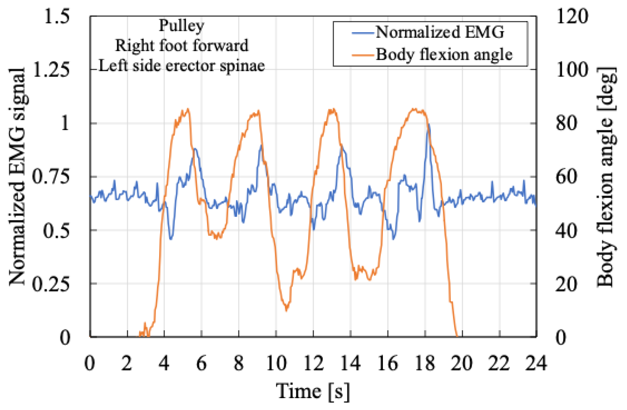
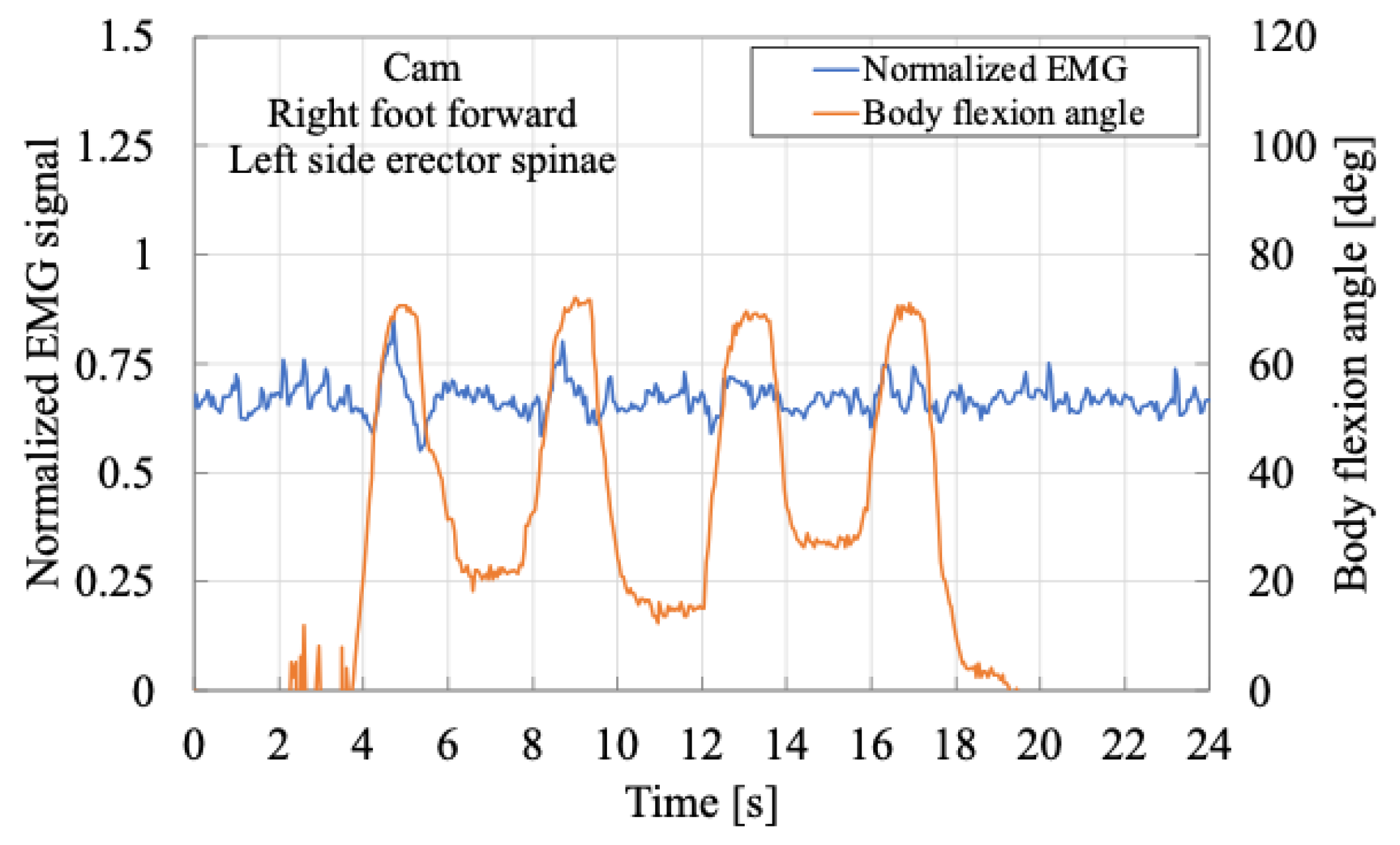
Next,
Figure 18 and
Figure 19 compare the muscle activity of the left erector spinae muscle in the semi-squatting posture with the right foot forward. In this case, a reduction in the peak myoelectric activity was observed when the cam mechanism was employed, indicating a favorable assistive effect.
Next,
Figure 20 and
Figure 21 present the trends in local maximum values of myoelectric activity for the left and right erector spinae muscles when using either the pulley or the cam, relative to the no-assistance condition.
Figure 20 shows results for the semi-squatting posture with the left foot forward while
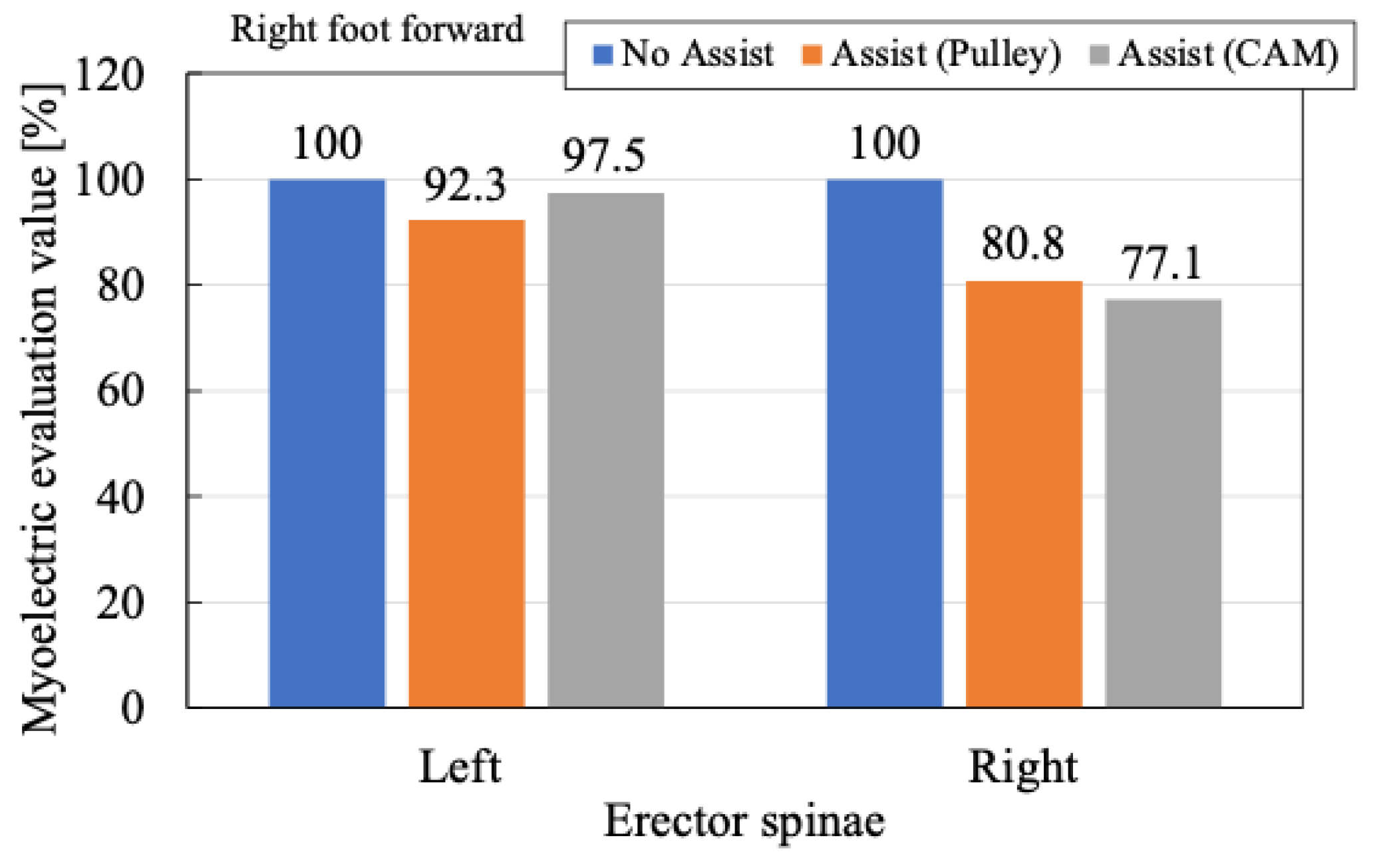
Figure 21 shows results for the right foot forward. These figures display the maximum myoelectric potentials recorded across a total of 16 semi-squatting postures with a staggered stance, normalized to the maximum value under the no-assistance condition (set as 100%).
The results indicate that the use of the SAEx leads to a reduction in the local maximum myoelectric potential, thereby demonstrating an assistive effect. Furthermore, a comparison between the cam and pulley cases reveals an overall tendency for greater reduction in muscle activity when the assistive force profile is adjusted using the proposed cam mechanism.
Regarding the relationship between leg position and assistive effect, the data suggest that the assistive effect is more pronounced on the side where the forward foot is placed while little to no effect is observed on the opposite side. Although quantitative variations exist, the reduction in the maximum myoelectric potential is approximately 20% when using the pulley and increases to about 20–30% when using the cam.
These findings suggest that the SAEx provides effective assistance even during twisted postures commonly observed in agricultural tasks, such as the semi-squatting posture with a staggered stance. Moreover, the assistive effect can be further enhanced by modulating the assistive force based on the body flexion angle, particularly by increasing the assistive force near the standing position through cam-based adjustment of the assistive force profile.
6. Conclusions
In this study, we investigated the assistive effect of the SAEx in a semi-squatting posture involving torso twisting, such as in the staggered stance frequently observed in agricultural tasks. To enhance the assistive effect, we proposed the use of a cam mechanism to adjust the assistive force profile according to the user’s body flexion angle. The effectiveness of this approach was experimentally evaluated. The main findings are summarized as follows:
In semi-squatting postures with a staggered stance, muscle activity in the erector spinae tends to be higher on the side where the forward foot is placed. The use of the SAEx was found to effectively reduce the peak muscle activity on that side.
In contrast, the erector spinae muscles on the rear foot side exhibited little to no reduction in activity, indicating that the assistive effect is asymmetrical and influenced by the direction of body twist.
Adjusting the assistive force profile using the cam led to a greater reduction in peak muscle activity compared to the conventional pulley mechanism. Specifically, the local maximum muscle activity decreased by approximately 20% with the pulley and by up to 30% with the cam-adjusted assistive force.
These results demonstrate that SAEx can effectively reduce peak erector spinae muscle activity in twisted squatting postures commonly encountered during agricultural labor.
However, the qualitative trends in muscle activity varied across trials, likely due to the complex nature of body movements in twisted postures. Further investigation is required to better understand these variations and to more precisely evaluate the assistive effect under diverse working conditions. In particular, it is also necessary to consider the individual physical characteristics of the subjects, such as muscle mass, body dimensions, and movement strategies, which may influence muscle activation patterns. Future work will aim to refine the evaluation methodology and expand the applicability of the SAEx in real-world agricultural environments.
Author Contributions
Conceptualization, N.S. (Naoki Saito); data curation, N.S. (Naoki Saito) and T.K.; formal analysis, N.S. (Naoki Saito); funding acquisition, N.S. (Naoki Saito); investigation, N.S. (Naoki Saito); methodology, N.S. (Naoki Saito) and T.S.; project administration, N.S. (Naoki Saito); resources, N.S. (Naoki Saito); software, T.K. and K.A.; supervision, N.S. (Naoki Saito) and N.S. (Norihiko Saga); validation, N.S. (Naoki Saito) and N.S. (Norihiko Saga); visualization, N.S. (Naoki Saito); writing—original draft, N.S. (Naoki Saito); writing—review and editing, N.S. (Naoki Saito), T.S., and N.S. (Norihiko Saga). All authors have read and agreed to the published version of the manuscript.
Funding
This work was supported by the Cabinet Office, Government of Japan, Regional Revitalization Grant.
Institutional Review Board Statement
This study was approved by the Ethical Review for Research Involving Human Subjects, Faculty of Science and Engineering, Akita Prefectural University (subsequent approval no.1).
Informed Consent Statement
The purpose and methods of the experiment were explained to all subjects involved in this experiment, and their consent to participate in the experiment was obtained.
Data Availability Statement
The research data are available from the corresponding author, N. Saito, on reasonable request.
Conflicts of Interest
The authors declare no conflicts of interest. The funders had no role in the design of the study; in the collection, analyses, or interpretation of data; in the writing of the manuscript; or in the decision to publish the results.
References
- Bloom, D.; Canning, D.; Lubet, A. Global Population Aging: Facts, Challenges, Solutions & Perspectives. Daedalus 2015, 144, 80–92. [Google Scholar] [CrossRef]
- Kirkhorn, S.R.; Earle-Richardson, G.; Banks, R.J. Ergonomic Risks and Musculoskeletal Disorders in Production Agriculture: Recommendations for Effective Research to Practice. J. Agromedicine 2010, 15, 281–299. [Google Scholar] [CrossRef]
- Fathallah, F.A.; Miller, B.J.; Miles, J.A. Low Back Disorders in Agriculture and the Role of Stooped Work: Scope, Potential Interventions, and Research Needs. J. Agric. Saf. Health 2008, 14, 221–245. [Google Scholar] [CrossRef]
- Xiang, H.; Stallones, L.; Keefe, T.J. Back Pain and Agricultural Work among Farmers: An Analysis of the Colorado Farm Family Health and Hazard Surveillance Survey. Am. J. Ind. Med. 1999, 35, 310–316. [Google Scholar] [CrossRef]
- Rosecrance, J.; Rodgers, G.; Merlino, L. Low Back Pain and Musculoskeletal Symptoms among Kansas Farmers. Am. J. Ind. Med. 2006, 49, 547–556. [Google Scholar] [CrossRef] [PubMed]
- Jo, H.; Park, H.-W.; Baek, S.; Kang, E.K. Low Back Pain in Farmers: The Association with Agricultural Work Management, Disability, and Quality of Life in Korean Farmers. Hum. Factors Ergon. Manuf. 2017, 27, 156–165. [Google Scholar] [CrossRef]
- Christopher Murray, J.L.; Rabiee, N. Global Burden of 369 Diseases and Injuries in 204 Countries and Territories, 1990–2019: A Systematic Analysis for the Global Burden of Disease Study 2019. Lancet 2020, 396, 1204–1222. [Google Scholar] [CrossRef]
- Tomioka, K.; Shima, M.; Saeki, K. Occupational Status and Self-Reported Low Back Pain by Gender: A Nation-Wide Cross-Sectional Study among the General Population in Japan. Environ. Health Prev. Med. 2021, 26, 111. [Google Scholar] [CrossRef]
- Thamsuwan, O. Overview of Passive Back-Supporting Exoskeleton Trials on Farms. In Proceedings of the 2022 Conference of the International Society for Agricultural Safety and Health, Fort Collins, CO, USA, 12–16 June 2022. [Google Scholar]
- Upasani, S.; Franco, R.; Niewolny, K.; Srinivasan, D. The Potential for Exoskeletons to Improve Health and Safety in Agriculture—Perspectives from Service Providers. IISE Trans. Occup. Ergon. Hum. Factors 2019, 7, 222–229. [Google Scholar] [CrossRef]
- Jakob, M.; Balaguier, R.; Park, H.; Trask, C. Addressing Exoskeleton Implementation Challenges: Case Studies of Non-Acceptance in Agriculture. J. Agromedicine 2023, 28, 784–796. [Google Scholar] [CrossRef]
- Omoniyi, A.; Trask, C.; Milosavljevic, S.; Thamsuwan, O. Farmers’ Perceptions of Exoskeleton Use on Farms: Finding the Right Tool for the Work(er). Int. J. Ind. Ergon. 2020, 80, 103036. [Google Scholar] [CrossRef]
- Xiloyannis, M.; Alicea, R.; Georgarakis, A.-M.; Haufe, F.L.; Wolf, P.; Masia, L.; Riener, R. Soft Robotic Suits: State of the Art, Core Technologies, and Open Challenges. IEEE Trans. Robot. 2022, 38, 1343–1362. [Google Scholar] [CrossRef]
- de Looze, M.P.; Bosch, T.; Krause, F.; Stadler, K.S.; O’Sullivan, L.W. Exoskeletons for Industrial Application and Their Potential Effects on Physical Work Load. Ergonomics 2016, 59, 671–681. [Google Scholar] [CrossRef] [PubMed]
- Toxiri, S.; Näf, M.B.; Lazzaroni, M.; Fernández, J.; Sposito, M.; Poliero, T.; Monica, L.; Anastasi, S.; Caldwell, D.G.; Ortiz, J. Back-Support Exoskeletons for Occupational Use: An Overview of Technological Advances and Trends. IISE Trans. Occup. Ergon. Hum. Factors 2019, 7, 237–249. [Google Scholar] [CrossRef]
- Hara, H.; Sankai, Y. Development of HAL for Lumbar Support. SCIS 2010, 2010, 416–421. [Google Scholar] [CrossRef]
- Miura, K.; Kadone, H.; Koda, M.; Abe, T.; Endo, H.; Murakami, H.; Doita, M.; Kumagai, H.; Nagashima, K.; Fujii, K.; et al. The Hybrid Assisted Limb (HAL) for Care Support, a Motion Assisting Robot Providing Exoskeletal Lumbar Support, Can Potentially Reduce Lumbar Load in Repetitive Snow-Shoveling Movements. J. Clin. Neurosci. 2018, 49, 83–86. [Google Scholar] [CrossRef]
- Ide, M.; Hashimoto, T.; Matsumoto, K.; Kobayashi, H. Evaluation of the Power Assist Effect of Muscle Suit for Lower Back Support. IEEE Access 2021, 9, 3249–3260. [Google Scholar] [CrossRef]
- Asbeck, A.T.; Dyer, R.J.; Larusson, A.F.; Walsh, C.J. Biologically-Inspired Soft Exosuit. In Proceedings of 2013 IEEE 13th International Conference on Rehabilitation Robotics (ICORR), Seattle, WA, USA, 24–26 June 2013. [Google Scholar] [CrossRef]
- Kazerooni, H.; Tung, W.; Pillai, M. Evaluation of Trunk-Supporting Exoskeleton. In Proceedings of the Human Factors and Ergonomics Society Annual Meeting, Seattle, WA, USA, 28 October–1 November 2019; Volume 63, pp. 1080–1083. [Google Scholar] [CrossRef]
- Mohri, S.; Inose, H.; Arakawa, H.; Yokoyama, K.; Yamada, Y.; Kikutani, I.; Nakamura, T. Development of Non-Rotating Joint Drive Type Gastrocnemius-Reinforcing Power Assist Suit for Squat Lifting. In Proceedings of the 2017 IEEE International Conference on Advanced Intelligent Mechatronics (AIM), Munich, Germany, 3–7 July 2017; pp. 851–856. [Google Scholar]
- Ali, A.; Fontanari, V.; Schmoelz, W.; Agrawal, S.K. Systematic Review of Back-Support Exoskeletons and Soft Robotic Suits. Front. Bioeng. Biotechnol. 2021, 9, 765257. [Google Scholar] [CrossRef]
- Toxiri, S.; Ortiz, J.; Masood, J.; Fernandez, J.; Mateos, L.A.; Caldwell, D.G. A Wearable Device for Reducing Spinal Loads during Lifting Tasks: Biomechanics and Design Concepts. In Proceedings of the 2015 IEEE International Conference on Robotics and Biomimetics (ROBIO), Zhuhai, China, 6–9 December 2015; pp. 2295–2300. [Google Scholar]
- Abdoli-E, M.; Agnew, M.J.; Stevenson, J.M. An on-Body Personal Lift Augmentation Device (PLAD) Reduces EMG Amplitude of Erector Spinae during Lifting Tasks. Clin. Biomech. 2006, 21, 456–465. [Google Scholar] [CrossRef]
- Schulte, H.F., Jr. The Characteristics of the McKibben Artificial Muscle; The Application of External Power in Prosthetics and Orthotics; National Academy Science, National Research Council: Washington, DC, USA, 1961. [Google Scholar]
- Toxiri, S.; Koopman, A.S.; Lazzaroni, M.; Ortiz, J.; Power, V.; de Looze, M.P.; O’Sullivan, L.; Caldwell, D.G. Rationale, Implementation and Evaluation of Assistive Strategies for an Active Back-Support Exoskeleton. Front. Robot. AI 2018, 5, 53. [Google Scholar] [CrossRef]
- Koopman, A.S.; Toxiri, S.; Power, V.; Kingma, I.; van Dieën, J.H.; Ortiz, J.; de Looze, M.P. The Effect of Control Strategies for an Active Back-Support Exoskeleton on Spine Loading and Kinematics during Lifting. J. Biomech. 2019, 91, 14–22. [Google Scholar] [CrossRef]
Figure 1.
Squatting assist exoskeleton using PAM (SAEx).
Figure 1.
Squatting assist exoskeleton using PAM (SAEx).
Figure 2.
Force exertion principle of the assistive force mechanism.
Figure 2.
Force exertion principle of the assistive force mechanism.
Figure 3.
Difference in the amount of assistive force in a half-squatting posture with a staggered stance. The orange arrows indicate the assistive force, and the red curved arrows represent the torque around the hip joint.
Figure 3.
Difference in the amount of assistive force in a half-squatting posture with a staggered stance. The orange arrows indicate the assistive force, and the red curved arrows represent the torque around the hip joint.
Figure 4.
McKibben-Type Pneumatic Artificial Muscle (PAM).
Figure 4.
McKibben-Type Pneumatic Artificial Muscle (PAM).
Figure 5.
Isometric contraction characteristic of PAM.
Figure 5.
Isometric contraction characteristic of PAM.
Figure 6.
Relationship between assistive force or pressure and body flexion angle of PAM built on the SAEx.
Figure 6.
Relationship between assistive force or pressure and body flexion angle of PAM built on the SAEx.
Figure 7.
Parameters of the rotational cam and outer shape of the designed cam.
Figure 7.
Parameters of the rotational cam and outer shape of the designed cam.
Figure 8.
Comparison of assistive force between pulley system and cam system.
Figure 8.
Comparison of assistive force between pulley system and cam system.
Figure 9.
Experimental system.
Figure 9.
Experimental system.
Figure 10.
Experimental scene.
Figure 10.
Experimental scene.
Figure 11.
Comparison of actual assistive force and designed assistive force.
Figure 11.
Comparison of actual assistive force and designed assistive force.
Figure 12.
Relation between body flexion angle and normalized EMG of left side elector spinae using pulley-embedded SAEx when the left foot is forward.
Figure 12.
Relation between body flexion angle and normalized EMG of left side elector spinae using pulley-embedded SAEx when the left foot is forward.
Figure 13.
Relation between body flexion angle and normalized EMG of left side elector spinae using cam-embedded SAEx when the left foot is forward.
Figure 13.
Relation between body flexion angle and normalized EMG of left side elector spinae using cam-embedded SAEx when the left foot is forward.
Figure 14.
Relation between body flexion angle and normalized EMG of right-side elector spinae using pulley-embedded SAEx when the left foot is forward.
Figure 14.
Relation between body flexion angle and normalized EMG of right-side elector spinae using pulley-embedded SAEx when the left foot is forward.
Figure 15.
Relation between body flexion angle and normalized EMG of right-side elector spinae using cam-embedded SAEx when the left foot is forward.
Figure 15.
Relation between body flexion angle and normalized EMG of right-side elector spinae using cam-embedded SAEx when the left foot is forward.
Figure 16.
Relation between body flexion angle and normalized EMG of right-side elector spinae using pulley-embedded SAEx when the right foot is forward.
Figure 16.
Relation between body flexion angle and normalized EMG of right-side elector spinae using pulley-embedded SAEx when the right foot is forward.
Figure 17.
Relation between body flexion angle and normalized EMG of right-side elector spinae using cam-embedded SAEx when the right foot is forward.
Figure 17.
Relation between body flexion angle and normalized EMG of right-side elector spinae using cam-embedded SAEx when the right foot is forward.
Figure 18.
Relation between body flexion angle and normalized EMG of left side elector spinae using pulley-embedded SAEx when the right foot is forward.
Figure 18.
Relation between body flexion angle and normalized EMG of left side elector spinae using pulley-embedded SAEx when the right foot is forward.
Figure 19.
Relation between body flexion angle and normalized EMG of left side elector spinae using cam-embedded SAEx when the right foot is forward.
Figure 19.
Relation between body flexion angle and normalized EMG of left side elector spinae using cam-embedded SAEx when the right foot is forward.
Figure 20.
Comparison of maximum myoelectric potentials of left and right erector spinae muscles in the experiment when the left foot is forward.
Figure 20.
Comparison of maximum myoelectric potentials of left and right erector spinae muscles in the experiment when the left foot is forward.
Figure 21.
Comparison of maximum myoelectric potentials of left and right erector spinae muscles in the experiment when the right foot is forward.
Figure 21.
Comparison of maximum myoelectric potentials of left and right erector spinae muscles in the experiment when the right foot is forward.
Table 1.
Parameters of the PAM.
Table 1.
Parameters of the PAM.
| Parameter | Amount |
|---|
| 24 deg |
| 210 mm |
| 229.87 mm |
| 20 mm |
| 1.488 |
| 0.10 MPa |
| Disclaimer/Publisher’s Note: The statements, opinions and data contained in all publications are solely those of the individual author(s) and contributor(s) and not of MDPI and/or the editor(s). MDPI and/or the editor(s) disclaim responsibility for any injury to people or property resulting from any ideas, methods, instructions or products referred to in the content. |
© 2025 by the authors. Licensee MDPI, Basel, Switzerland. This article is an open access article distributed under the terms and conditions of the Creative Commons Attribution (CC BY) license (https://creativecommons.org/licenses/by/4.0/).


