Article

Dynamics Modeling and Control Method for Non-Cooperative Target Capture with a Space Netted Pocket System

1
College of Mechanical and Electrical Engineering, Harbin Engineering Universiity, 145 Nangtong Street, Harbin 150001, China
2
School of Astronautics, Haribin Institute of Techinology, 92 Xidazhi Street, Harbin 150001, China
3
Beijing Institute of Control Engineering, Beijing 100094, China
4
Beijing Institute of Astronautical Systems Engineering, 1 Nandahongmen Road, Beijing 100076, China
*
Author to whom correspondence should be addressed.
Actuators 2025, 14(7), 358; https://doi.org/10.3390/act14070358
Submission received: 30 May 2025 / Revised: 10 July 2025 / Accepted: 15 July 2025 / Published: 21 July 2025
(This article belongs to the Section Control Systems)

Abstract

The space flexible netted pocket capture system provides a flexible and stable solution for capturing non-cooperative space objects. This paper investigates the control problem for the capture of non-cooperative targets undergoing motion. A dynamic model of the capturing net is established based on the absolute nodal coordinate formulation (ANCF) and equivalent plate–shell theory. A contact collision force model is developed using a spring–damper model. Subsequently, a feedforward controller is designed based on the estimated collision force from the dynamic model, aiming to compensate for the collision effects between the target and the net. By incorporating the collision estimation data, an extended state observer is designed, taking into account the collision estimation errors and the flexible uncertainties. A sliding mode feedback controller is then designed using the fast terminal sliding mode control method. Finally, simulation analysis of target capture under different motion states is conducted. The results demonstrate that the spacecraft system’s position and attitude average flutter amplitudes are less than 10 2 m and 10 2 deg. In comparison to standard sliding mode control, the designed controller reduces the attitude jitter amplitude by an order of magnitude, thus demonstrating its effectiveness and superiority.

1. Introduction

With the increasing intensity of space activities, various satellites are launched into Earth orbit. The majority of these satellites lack recovery capabilities after their lifespan, leading to a sharp increase in the number of large space debris in low Earth orbit. This poses a serious threat to the safe operation of satellites in orbit [1]. To address the safety issues caused by space debris, many researchers have proposed various debris capture methods. The primary methods for capturing space debris include robotic arm capture [2,3], tethered capture [4,5], net capture [6,7,8], and spacecraft mechanical claw encirclement capture [9,10]. Targeting spherical defunct satellites (e.g., Dong Fang Hong 1), our research group previously proposed a space netted pocket capture system that combines flexible nets and mechanical claw encirclement, offering a larger capture range and greater flexibility. Furthermore, a dynamic analysis of the non-cooperative target capture process was conducted for this method [11], as shown in Figure 1.
However, space debris is rarely stationary in actual capture processes. During capture, collisions between the moving target and the net generate significant time-varying collision forces, which can induce the reverse motion of the captured target. This can further lead to more collisions, increasing the uncertainty of the spacecraft’s attitude and potentially causing the spacecraft to lose control [12,13]. Therefore, it is necessary to investigate capture control methods that account for collisions between the target and the net.
For the collision calculations between the flexible net and the captured target, the basic idea is to refer to rigid body collision calculation methods. By obtaining the penetration depth between the net and the target, collision forces are calculated using the Hertz model and Coulomb friction model [14,15]. Zhang et al. [16] addressed the dynamics analysis of the aircraft carrier arresting gear system during the arresting process. They discretized the steel cable into multiple rigid cable lumped masses and simulated the dynamic contact between the tail hook/pulley and the cable in the arresting gear system using the Hertz model, referencing the discrete element method. Shan [17] investigated the dynamics analysis of the process of capturing space debris with a net. They combined Hertz contact theory and Coulomb friction theory to calculate collision forces for capturing both spherical and cubic debris. Rui et al. [18] proposed a contact force model based on a combination of an improved Hertz model and a LuGre friction model, enabling accurate estimation of contact forces between the end-effector and the non-cooperative space target without the need for additional sensors. Furthermore, they analyzed the contact characteristics between the end-effector and the target. Zhao et al. [19] addressed the specific situation that the target was not contacted during the capture process due to the asymmetrical configuration of the net. They constructed two contact force models using the continuous compliance method and the modified Coulomb dry friction law. Subsequently, a simulation of the capture dynamics response under non-ideal conditions was carried out.
Concerning the control of complex multi-body capture mechanisms, many researchers have focused on control methods for mechanical claw or net capture mechanisms. Zhao et al. [20,21] addressed the chattering problem during the net encirclement capture process. They proposed a pulse adaptive super-twisting sliding mode control scheme based on the spacecraft’s attitude data. This method can converge the state vector to the origin and maintain it there within a short time. Zhang [22] addressed the envelope control problem of capturing asteroids with a net. He applied sliding mode control to the design of a neural network controller and proposed a fast envelope encirclement control method. The simulation results show that the envelope capture of a large asteroid was completed in 206.8 min. Han [23] proposed a compliant control scheme that does not require contact force sensors to solve the problem of flexible clawcapture mechanisms control. By analyzing the changes in attitude angles and contact force of the satellite and the target during the capture process, the effectiveness of the control system was verified. As for the uncertainty problem in the capture process, Yang [24] addressed the problem of capturing non-cooperative targets carrying flexible components. First, the nominal inertia was introduced to create a comprehensive disturbance term. Then, combined with the spacecraft’s attitude data, a flexible non-cooperative target attitude stable negative virtual static output feedback control method was proposed. This method achieved stable control of the flexible non-cooperative target.
In summary, numerous studies have focused on collision modeling between rope nets and targets, as well as space debris capture control. However, research on the dynamics modeling and control of space netted-pocket debris capture mechanisms is limited, particularly regarding the capture control of space debris under complex motion. Further analysis and research are needed.This paper focuses on the capture control problem involving the collisions between the target and the net and presents a collision feedforward compensation–sliding mode capture control method. Initially, a dynamics model and a collision force model for the rope net are established using the equivalent plate–shell method and the Hertz contact model, respectively. Subsequently, collision feedforward compensation is developed based on the dynamics model and parameter identification. A hybrid collision feedforward–sliding mode control feedback controller is then designed. Simulation analyses of non-cooperative target capture are performed. The results showing that the position and attitude chatter amplitude of the spacecraft remain below 10 2 m and 10 2 deg throughout the capture process. Compared to the conventional sliding mode control, the attitude jitter is reduced by an order of magnitude, thereby demonstrating the effectiveness and superiority of the developed controller.
The structure of this paper is as follows: in Section 2, the dynamic model of the net is established based on the equivalent plate-shell theory and ANCF. The contact dynamics model between the target and the net is established based on the Hertz model. In Section 3, a feedforward controller is designed based on the dynamic model collision estimation. By embedding collision prediction data, an extended observer considering estimation errors and flexible uncertainties is designed. Then, a sliding mode feedback controller is designed via the fast terminal sliding mode control method. In Section 4, the dynamic simulation of the capture process under different target motion conditions is given, and the simulation results are analyzed and discussed. Finally, Section 5 summarizes the work of this paper.

2. Dynamic Modeling of the Space Netted Pocket System

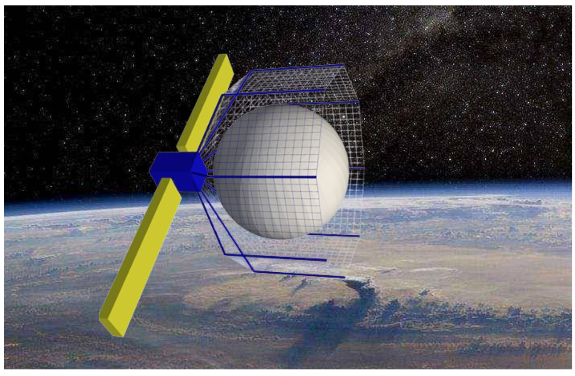
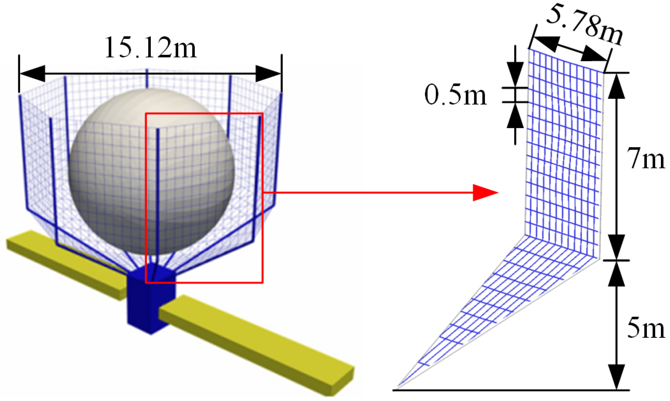
2.1. Structure of the Netted Pocket Capture System

The net system in this paper is consistent with previous research [11]. The net capture system is divided into eight net modules, each net module is 5.78 m long and 12 m high. The structure of the space netted pocket system is shown in Figure 2.

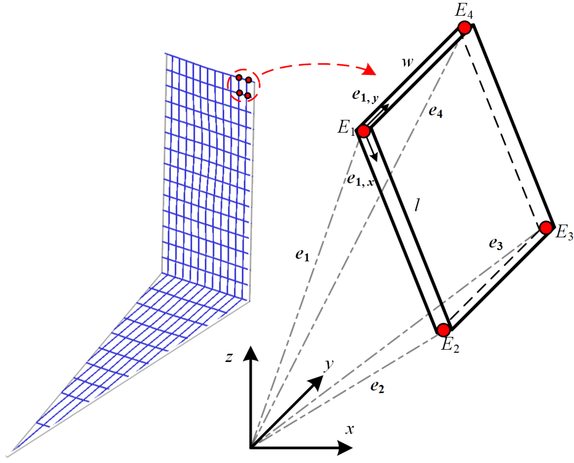
2.2. Dynamics Model of the Rope Net

In this section, the flexible net dynamic model is constructed using ANCF based on the equivalent plate–shell elements.
This method describes the internal deformation and motion of a single net grid through the shape function of the plate–shell element. Subsequently, the dynamic model of the flexible net grid element is constructed through the constitutive model of the equivalent plate–shell. This method can effectively balance the calculation accuracy and calculation efficiency of the model. The equivalent plate–shell element is shown in Figure 3.
This paper derives the strain energy of the equivalent plate–shell element based on the Kirchhoff thin plate hypothesis and Green’s formula. Then, the dynamic model of the rope net was derived based on the ANCF and equivalent plate-shell elements, by retaining the nonlinear terms in the strain energy. For the dynamic modeling of flexible nets, it is first necessary to select the generalized coordinates of the absolute nodes. Natural coordinates are obtained through interpolation based on these coordinates. The element kinetic energy is calculated by differentiating these coordinates, thus obtaining the system mass matrix. The element potential energy is calculated using the Green strain principle, and the element generalized force is calculated using the virtual work principle. Finally, the dynamic model of the flexible net is constructed. Defining the displacement and slope vectors of its four nodes as generalized coordinates, the generalized coordinates e for the flexible net are as follows:
e = e 1 T e 1 , x T e 1 , y T e 2 T e 2 , x T e 2 , y T e 3 T e 3 , x T e 3 , y T e 4 T e 4 , x T e 4 , y T T
where x and y are the material coordinates of the plate–shell element, and l and w are the length and width of the element in the initial state, which satisfy 0 x l , 0 y w . Then, the position vector of any point in the flexible net element can be obtained by interpolating the generalized coordinates:
r = Se = S 1 I S 2 I S 3 I S 4 I S 5 I S 6 I S 7 I S 8 I S 9 I S 10 I S 11 I S 12 I e
where S n is the shape function of the equivalent plate–shell element, which is expressed as follows:
S 1 = ( ζ 1 ) ( η 1 ) ( 2 η 2 η + 2 ζ 2 ζ 1 ) S 2 = l ζ ( ζ 1 ) 2 ( η 1 ) S 3 = w η ( η 1 ) 2 ( ζ 1 ) S 4 = ζ ( 2 η 2 η + 2 ζ 2 3 ζ ) ( η 1 ) S 5 = l ζ 2 ( η 1 ) ( ζ 1 ) S 6 = w η ζ ( η 1 ) 2 S 7 = η ζ ( 1 3 ζ 3 η + 2 η 2 + 2 ζ 2 ) S 8 = l ζ 2 η ( ζ 1 ) S 9 = w ζ η 2 ( η 1 ) S 10 = η ( ζ 1 ) ( 2 ζ 2 ζ 3 η + 2 η 2 ) S 11 = l ζ η ( ζ 1 ) S 12 = h η 2 ( ζ 1 ) 2 ( η 1 ) ζ = x / l η = y / w
Taking the derivative of Equation (3), the velocity of any point can be expressed as follows:
r ˙ = S e ˙
From the definition of kinetic energy, the kinetic energy expression of the equivalent plate–shell element is
T = 1 2 e ˙ T V ρ S T S d V e ˙
The mass matrix of the element can be expressed as follows:
M = V ρ S T S d V
where ρ is the equivalent density of the plate–shell element. The above equation is a constant. Therefore, it does not need to be updated at each step. The Green strain tensor of any point in the equivalent plate–shell element can be expressed as follows:
E = 1 2 d r d X T d r d X I
where X = [ x , y ] T is the element material coordinate. Based on Kirchhoff thin plate theory, the transverse shear deformation is neglected. Then, substituting Equation (7) into the element constitutive equation, the elastic potential energy of the plate–shell element can be expressed as follows:
U = 1 2 V E T CE + κ T C κ d V
where C is the elastic tensor. E is the strain tensor. κ is the curvature of the neutral surface of the element.
The generalized force of the plate–shell element can be obtained by the virtual work principle as follows:
Q = V S T f d V
where f is the distributed load acting on the plate–shell element.
Finally, based on the Lagrange equation, considering structural damping, the dynamic model of the flexible net can be obtained as follows:
F u n c = d e f M e ¨ + C e ˙ + K e + B e T λ Q Q v = 0 B e e ˙ , e , t = 0
where Q v is the nonlinear force term. B e is the constraint equations. λ is the Lagrange multiplier. C is the damping matrix. K is the stiffness matrix.

2.3. Collision and Friction Force Modeling

Using the principle of virtual work, the collision and friction forces acting on the unit surface can be transformed into generalized nodal forces of the element Q c f , that is
Q c f = N ( p ) T F
where p is the element coordinate corresponding to the element collision point. F is the collision and friction force acting on the collision point, which can be calculated by the Hertz contact model as follows:
F = F n n + F t t
where n is the collision normal unit vector, and t is the tangential unit vector.

2.3.1. Collision Force Modeling

The collision process is equivalent to a nonlinear spring-damping model. Restoring forces during the collision are modeled using elastic contact forces, while energy loss during the collision is modeled using nonlinear damping forces. The direction of the elastic contact force is opposite to the direction in which the colliding bodies are embedded in each other, and is always a pressure. The direction of the nonlinear damping force is opposite to the direction of the relative motion of the colliding bodies. According to the Hertz theory, the normal contact force is as follows:
F n = F K + F C = K c δ n + C c δ ˙
In this equation, K c is the contact stiffness coefficient; C c is the contact damping coefficient; δ n is the normal penetration depth; and δ ˙ is the penetration velocity;
(1)
Normal Elastic Component F K = K c δ n
The normal elastic component is equivalent to a nonlinear spring. The contact stiffness coefficient is related to the material properties and the geometry of the contact surface. According to Hertz contact theory, the contact stiffness for the collision between the net and the captured target can be derived as follows:
K c = 4 3 R * E *
where R * = 1 2 R 1 2 , R is the radius of curvature at the collision point. E * = 1 υ 1 2 E 1 + 1 υ 2 2 E 2 1 , υ 1 are the Poisson’s ratio of the net, υ 2 is the Poisson’s ratio of the captured target. E 1 and E 2 are the Young’s moduli of the rope net and the target, respectively.
(2)
Nonlinear Damping Component F C = C c δ ˙
In the damping component, the contact damping coefficient is
C c = 3 K c 1 e 2 4 v 0 δ n = 3 1 e 2 4 v 0 F K
where e is the recovery coefficient, and v 0 is the initial collision velocity at the collision point.
In practical applications, our research team has previously developed a vision-based dynamics parameter identification method [25] that is capable of rapidly and accurately providing standardized dynamics parameters of the target. This enables the determination of the relative velocity between the target and the spacecraft, as well as the penetration depth. This supports the estimation of collision and friction forces. By identifying the rope net deformation using a depth camera during the collision, the target’s penetration depth δ c and penetration velocity δ ˙ at the moment of contact can be obtained. Substituting these values into Equations (13)–(15) allows for the determination of the normal collision force F c at the current time.

2.3.2. Friction Force Modeling

The friction force changes continuously with the relative motion of the two bodies during contact and collision, and it exhibits nonlinear hysteresis. Since the contact surfaces are sliding against each other, the tangential contact force is defined as the Coulomb friction model. According to Coulomb friction, the friction force is as follows:
F t = μ v t F n
where μ is the coefficient of friction, which is determined by the tangential relative velocity v t . Furthermore, during practical application, the vision-based parameter identification method can be used to obtain the relative velocity v t between the target and the spacecraft. By substituting this value into Equation (16), the friction force at that instant can be calculated.

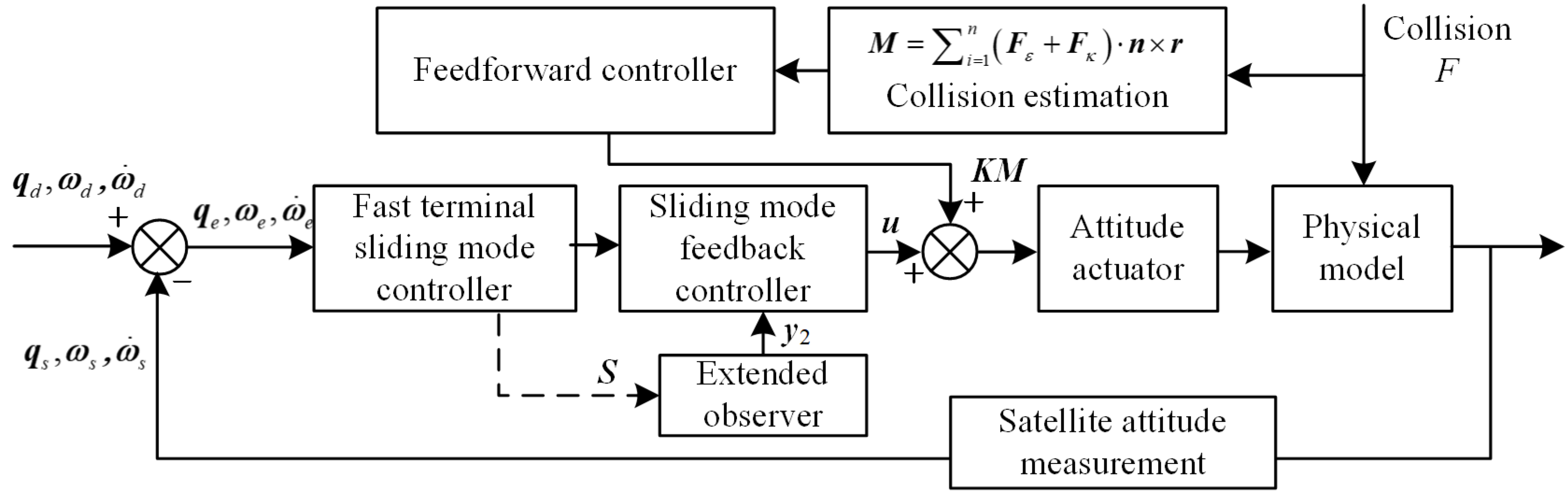
3. Design of a Collision Feedforward Sliding Mode Capture Controller

The capture process is shown in Figure 4, which mainly includes two steps: closing the mouth to encircle the target after approaching the target, and dragging the target. The rods realize the tightening of the net mouth through hinges. The rope net is kept in a tensioned state through the contraction of the winches at the ends. After tightening the net, the target is then towed, thereby achieving the capture of a non-cooperative target.
The feedforward–sliding mode control feedback hybrid controller based on predictive model collision isshown in Figure 5. The impact of the collision between the target and the spacecraft on the attitude during the capture process is considered. The collision force is then estimated using the dynamic model, and a feedforward controller is designed to compensate for the resulting collision disturbance. By embedding collision estimation data, an extended observer considering estimation errors and flexible uncertainties is designed. Finally, a sliding mode feedback controller is designed using the fast terminal sliding mode control method.
Based on the net and collision dynamics model established in Section 2, the collision force F n , friction force F t , and collision position r can be obtained. The estimation result M e of the collision torque at the current moment can be calculated. Considering that the collision disturbance is a step large disturbance, this section regards the feedforward control as a proportional link. Compensation for large collision disturbances is achieved by adding a moment control signal KM to the jet attitude actuators. In addition, due to the influence of estimation errors, changes in the material parameters of the net after long-term in-orbit operation, etc., there are still some uncertain disturbance effects after predictive feedforward control. Therefore, the feedback control link is needed, considering that the nonlinear sliding mode control method has the characteristics of being insensitive to parameter uncertainty and disturbances [26]. The feedback control algorithm in this section is based on the nonlinear sliding mode control method to achieve the compensation of uncertain small disturbances. Its fast terminal sliding mode surface is designed as follows:
S = ω e + 2 k 1 φ 1 ( q e ) sig α 1 ( q ˜ e ) + 2 k 2 φ 1 ( q e ) sig α 2 q ˜ e
where φ is the deviation quaternion matrix, which can be expressed as:
φ = q ˜ e × + q e 0 I 3 × 3 q e 0 = q ˜ d T q ˜ + q 0 q d 0 q ˜ e = q d 0 q ˜ + q ˜ d × q ˜ q 0 q ˜ d
where k 1 and k 2 are sliding surface coefficients, q d is the desired quaternion, and q e is the deviation quaternion. ω e is the deviation angular velocity. sig ( · ) is the sign function. α 1 and α 2 are sign function coefficients, which meet the following constraints:
α 1 = α 11 α 12 > 1 , 0 < α 2 = α 21 α 22 < 1
where the parameters α 11 , α 12 , α 21 , α 22 are positive odd numbers.
In order to prevent controller singularity, when the deviation quaternion | q e i | < ψ , the sliding mode surface S F = [ S F 1 , S F 2 , S F 3 ] T is
S F i = ω e + 2 k 1 φ 1 ( q e ) sig α 1 ( q ˜ e i ) + 2 k 2 φ 1 ( q e ) ι 1 q ˜ e i + ι 2 sig 1.5 q ˜ e i
where ι 1 = ( 2 α 2 ) ψ α 2 1 , ι 2 = ( α 2 1 ) ψ α 2 1.5 . Its convergence proof is as follows. Take the Lyapunov function and its derivative as
V = 1 2 q e T q ˜ e
V ˙ = q e T q ˜ ˙ e
From S = 0 , Equation (20) can be derived as follows:
ω e = 2 k 1 φ 1 ( q e ) sig α 1 ( q ˜ e ) + 2 k 2 φ 1 ( q e ) sig α 2 q ˜ e
Then, the derivative of V can be further written as follows:
V ˙ = q e T 1 2 φ ( q e ) 2 k 1 φ 1 ( q e ) sig α 1 ( q ˜ e ) + 2 k 2 φ 1 ( q e ) sig α 2 q ˜ e = q e T k 1 sig α 1 ( q ˜ e ) + k 2 sig α 2 q ˜ e k 1 i = 1 3 q ˜ e i 2 α 1 + 1 2 + k 2 i = 1 3 q ˜ e i 2 α 2 + 1 2
Then, according to the literature [27], it can be proved that
i = 1 3 q ˜ e i 2 α 1 + 1 2 3 1 α 1 2 i = 1 3 q ˜ e i 2 α 1 + 1 2 , i = 1 3 q ˜ e i 2 α 2 + 1 2 3 1 α 2 2 i = 1 3 q ˜ e i 2 α 2 + 1 2
Then, the derivative of V is further derived to obtain
V ˙ k 1 3 1 α 1 2 i = 1 3 q ˜ e i 2 α 1 + 1 2 k 2 3 1 α 2 2 i = 1 3 q ˜ e i 2 α 2 + 1 2 k 1 3 1 α 1 2 V α 1 + 1 2 k 2 3 1 α 2 2 V α 2 + 1 2
Then, at the finite time, t 0 T 0 , q ˜ e = 0 , ω e = 0 , q e 0 = ± 1 . Furthermore, based on the fast terminal sliding mode controller, a finite-time extended observer is designed to compensate for the influence of estimation errors and flexible uncertainty on the controller. According to Equation (20), the derivative of the sliding mode function can be written as follows:
S ˙ F = ω ˙ e + 2 α 1 k 1 φ 1 q e diag q ˜ e i α 1 1 q ˜ . e + 2 α 2 k 2 φ 1 q e diag q ˜ e i α 2 1 + 2 k 1 φ ˙ 1 q e sig α 1 q ˜ e + 2 k 2 φ ˙ 1 q e sig α 2 q ˜ e
Considering the inertia uncertainty caused by the collision estimation error of the flexible net, let the spacecraft inertia be J = J 0 + Δ J . In this equation, J 0 is the spacecraft system inertia, and Δ J is the system inertia uncertainty caused by the collision estimation error. Then, in combination with Equation (27), the following can be obtained:
J S ˙ = ( J 0 + Δ J ) ω ˙ e + 2 α 1 k 1 φ 1 ( q e ) diag q ˜ e i α 1 1 q ˜ ˙ e + 2 α 2 k 2 φ 1 ( q e ) diag q ˜ e i α 2 1 + 2 k 1 φ ˙ 1 ( q e ) sig α 1 ( q ˜ e ) + 2 k 2 φ ˙ 1 ( q e ) sig α 2 ( q ˜ e )
The spacecraft attitude dynamics equation is as follows:
J ω ˙ + ω × J ω = u + d
where u is the spacecraft control torque. d is the external uncertain disturbance.
Then, the dynamics equation of the spacecraft relative attitude tracking can be written as follows:
J ω ˙ e = ( ω e + A ( q e ) ω d ) × J ( ω e + A ( q e ) ω d ) + J ( ω e , × A ( q e ) ω d A ( q e ) ω ˙ d ) + u + d
where A ( q e ) is the attitude rotation matrix corresponding to the error quaternion, which can be expressed as follows:
A ( q e ) = 2 q ˜ e q ˜ e T + ( q e 0 2 q ˜ e T q ˜ e ) I 3 × 3 2 q e 0 q ˜ e ×
where ω d is the desired angular velocity, and ω e is the deviation angular velocity, ω e = ω A ( q e ) ω d . Then, substituting the system dynamics Equation (30) into Equation (28),
J S ˙ = ω e + A q e ω d × J 0 ω e + A q e ω d + J 0 ω e × A q e ω d A q e ω ˙ d + α 1 k 1 J 0 φ 1 diag q ˜ e i α 1 1 φ ω e + α 2 k 2 J 0 φ 1 diag q ˜ e i α 2 1 φ ω e + 2 k 1 J 0 φ ˙ 1 sig α 1 q ˜ e i α 1 1 + 2 k 2 J 0 φ ˙ 1 sig α 2 q ˜ e i α 2 1 ω e + A q e ω d × Δ J ω e + A q e ω d + Δ J ω e × A q e ω d A q e ω ˙ d Δ J ω e + u + d
Let G represent the known state of the system, and D represent the unknown state of the system, which can be expressed as follows:
G = ω e + A q e ω d × J 0 ω e + A q e ω d + J 0 ω e × A q e ω d A q e ω ˙ d + α 1 k 1 J 0 φ 1 diag q ˜ e i α 1 1 φ ω e + α 2 k 2 J 0 φ 1 diag q ˜ e i α 2 1 φ ω e + 2 k 1 J 0 φ ˙ 1 sig α 1 q ˜ e i α 1 1 + 2 k 2 J 0 φ ˙ 1 sig α 2 q ˜ e i α 2 1
D = ω e + A q e ω d × Δ J ω e + A q e ω d + Δ J ω e × A q e ω d A q e ω ˙ d + d Δ J ω e
Then, the system equation can be written as follows:
J S ˙ = G + D + u
Let x ˙ 1 = J S ˙ , x 2 = D , x ˙ 2 = z . Equation (35) can be further written as follows:
x ˙ 1 = G + x 2 + u x ˙ 2 = z t
Then, the expansion observer is designed as follows:
y ˙ 1 = G * + y 2 + u + β 1 Γ sig o 1 x 1 y 1 + γ 1 1 Γ sig ζ 1 x 1 y 1 y ˙ 2 = β 2 Γ sig o 2 x 1 y 1 + γ 2 1 Γ s i g ζ 2 x 1 y 1 + η sig x 1 y 1
where β 1 , β 2 , γ 1 , γ 2 , and η are observation gains. The constraint η > maxz must be satisfied. o i and ζ i are sign function coefficients, which can be expressed as follows:
o 1 1 κ , 1 o 2 = 2 o 1 1 ζ 1 1 , 1 + κ ζ 2 = 2 ζ 1 1
y 1 and y 2 are the predictions of J 0 S and D , respectively; Γ is the prediction coefficient, which should satisfy the following form:
Γ = 0 t T 1 else
Then, let the observation error E 1 = x 1 y 1 , E 2 = x 2 y 2 ; the observation error can be expressed as the following equation:
E ˙ 1 = E 2 β 1 Γ sig o 1 E 1 γ 1 1 Γ sig ζ 1 E 2 E ˙ 2 = β 2 Γ sig o 2 x 1 y 1 + γ 2 1 Γ s i g ζ 2 x 1 y 1 + η sig x 1 y 1 + z t
By selecting appropriate observation gains β 1 , β 1 , γ 1 , γ 1 , the observation error E 1 converges to 0 in a fixed time T 1 , and E 2 converges to a small value ν in a fixed time t < T 1 + T 2 . The definitions of T 1 and T 2 are as follows:
T 1 max { H } min { P } 2 1 o 1 ζ 1 1 2 2 min { H } max { H } T 1 o 1 1 ζ 1 + T T 2 ν η max { z }
where H = H T , P = P T , and satisfy
Q T H + HQ = P Q = γ 1 I 3 × 3 I 3 × 3 γ 2 I 3 × 3 0
Its convergence proof is as follows. Let the Lyapunov function as
V 2 = ι T H ι
where ι = [ s i g ( E 1 ) T sig 1 / ζ 1 ( E 2 ) ] (when t T ), ι = [ sig ( E 1 ) T s i g 1 / o 1 ( E 2 ) ] (when t > T ).
H is defined by Equation (41). According to the literature [28], it can be proved that
V ˙ 2 ( 1 , ι ) = ι ˙ T H ι + ι T H ι ˙ = E T Q T H + HQ E = E T ( P ) E 0
Q , P are also defined in Equation (41). Then the following conclusion can be obtained:
V 2 ( 1 , ι ) = ι T H ι max { H } ι 2 V ˙ 2 ( 1 , ι ) = E T ( P ) E min { P } ι 2
Then, Equation (45) can be written as
V ˙ 2 ( 1 , ι ) max H min P V 2 ( 1 , ι )
Further, according to the calculation time t, it can be written in segments as follows:
V ˙ 2 ( 1 , ι ) max H min P V 2 0.5 ( 1 + ζ 1 ) ( ζ 1 , ι ) , t T max H min P V 2 0.5 ( 1 + o 1 ) ( o 1 , ι ) , t > T
When t = T , V 2 ( ζ 1 , ι ) satisfies
V 2 ζ 1 , ι ζ 1 1 2 min { P } max { H } T 2 1 ζ 1
Since o 1 ( 1 κ , 1 ) , V 2 ( ζ 1 , ι ) is limited to V 2 ( o 1 , ι ) , the observation error converge to near zero within a fixed time [29].
According to the sliding mode controller and the extended observer designed above, the feedback compensation of the estimation error and the flexible uncertainty of the net can be realized. Then, the feedforward control torque M is added as follows:
u = k 3 sig α 3 S + k 4 sig α 4 S + k 5 S + y 2 + G + KM
where k 3 , k 4 , k 5 , α 3 and α 4 are control parameters. These control parameters satisfy k 3 , k 4 , k 5 > 0, α 3 > 1 and 0 < α 4 < 1. S F is the sliding mode surface defined by Equation (20). y 2 is the parameter estimated by Equation (37).
The convergence proof is as follows. Let the Lyapunov function as
V 3 = 1 2 S F T J S F
Then from Equation (50), we can obtain
V ˙ 3 = 1 2 S T J S ˙ = 1 2 S T k 3 sig α 3 S k 4 sig α 4 S k 5 S y 2 + x 2
Define E = [ E 1 T , E 2 T ] T as the observation error matrix; then, it can be proved that
S F T y 2 + x 2 S F E
Equation (51) can be further derived as follows:
V ˙ 3 k 3 S F T sig α 3 S F k 4 S F T sig α 4 S F k 5 S F T S F + S F | E | k 3 3 1 α 3 2 2 max J R 0 V 3 α 3 + 1 2 k 4 3 1 α 4 2 2 max J R 0 V 3 α 4 + 1 2
Therefore, it can be proved that the controller can converge to stability in a fixed time. Simulations will be conducted based on realistic capture conditions to analyze control accuracy and attitude stability, and to verify the effectiveness of the proposed method.

4. Dynamic Simulation Results and Analysis

4.1. Dynamic Simulation and Analysis of Escaping Target Capture

In this subsection, a capture dynamics simulation analysis was performed to investigate scenarios in which the target escapes. The spacecraft has a mass of 1210 kg and principal moments of inertia [ I x , I y , I z ] = [4282, 12,736, 14,498] (kg· m 2 ). The non-cooperative target has a mass of 400 kg and principal moments of inertia [ I x , I y , I z ] = [1210, 1210, 1210] (kg· m 2 ). The rope net is made of Kevlar 49, which has a Young’s modulus of 124 GPa and a density of 1.44 g/cm 3 . Controller parameters are shown in Table 1. Referring to the working condition settings of the net capturing satellite [30], the target’s escape velocity was set to 5 mm/s in the negative y-axis direction. The system capture process is shown in Figure 4 in Section 3: the net is gathered from 0 to 10 s, and the target is translated and dragged in the y direction from 10 to 20 s.
In this working condition, the simulation results are shown in Figure 6, Figure 7 and Figure 8. The blue line represents the capture stage and the yellow line represents the dragging stage. As shown in Figure 6, the collision force is greatest in the y direction during capture, making it the dominant collision direction.
The results presented in Figure 7 and Figure 8 show that, during the dragging phase, the target’s motion is closely coupled with the spacecraft along the y-axis, indicating successful capture. This is evidenced by the target’s center of mass remaining within the rope net system. Significantly, no major attitude oscillations were observed, validating the hybrid controller’s capability for stable target acquisition. Furthermore, during the complete capture and drag operation, the spacecraft’s positional jitter was maintained at the 10 2 m scale, and the attitude jitter was within the 10 2 deg scale. A reduction in attitude jitter of one order of magnitude compared to conventional sliding mode control was also achieved. This demonstrates that the proposed collision feedforward–sliding mode controller reliably captures the escaping target and maintains the stable pose characteristics of the target and spacecraft throughout the capture-dragging phase, illustrating the controller’s effectiveness.
In summary, when capturing the escaping target, the capture collision force will rapidly decay to near 0 after the collision. A consistent attitude between the target and spacecraft during the dragging process indicates that the designed controller effectively reduces the impact of space debris with escape velocity, enhancing capture performance.

4.2. Dynamic Simulation and Analysis of Spinning Target Capture

This subsection mainly refers to the remote sensing data of the rotation speed of the discarded EnviSat and Cbers-2B satellites [31,32]. A dynamic simulation analysis was carried out for the condition where the target had a spin speed of 2 °/s about the y-axis. The parameters of the spacecraft, target, net, and control system are consistent with those in Section 4.1. The simulation results are shown in Figure 9, Figure 10 and Figure 11.
It can be seen from Figure 11 that compared to the escaping target working condition, the collision force amplitude and collision frequency in the y and z directions increase during capture. This is primarily due to the target’s inherent spin. During the capture process, the spinning target repeatedly collided with the rope net, leading to a large initial collision force at this time. However, in the dragging stage, the target center of mass is located on the axis of symmetry of the octahedral net, and each net surface is uniformly stressed on the target. The net’s detumbling effect mainly comes from friction, so the collision force remains relatively constant during the dragging process. As shown in Figure 11, the detumbling effect only increased the number of collisions and had a minimal impact on the spacecraft’s attitude. Furthermore, the target and the spacecraft move synchronously along the y direction together in the dragging stage, indicating that the target is captured successfully. The overall position and attitude change magnitude of spacecraft is at the level of 10 2 m and 10 2 deg. These results confirm that the feedforward control signal provided good compensation for the impact force, indicating that the control method presented in this paper is well-suited for capturing non-cooperative targets with spin rates.
In summary, in the case of capturing a spinning target, the existence of the detumbling effect leads to an increase in the collision force in the secondary direction between the target and the net during the capture process. However, since the collision estimation feedforward controller provided good compensation for the collision process, the spacecraft attitude did not significantly change throughout the capture. The position and attitude flutter amplitude of the spacecraft is less than 10 2 m and 10 2 deg. These results confirm that the proposed control method can reduce the rotational disturbances from spinning targets, improving pose stability during the control process.

5. Conclusions

This paper has studied the control problem of capturing non-cooperative targets under motion by the spatial net-bag mechanism. First, a dynamic model of the net is established based on the equivalent plate–shell theory and the absolute nodal coordinate method. After that, a collision dynamics model of the net and the target is established based on the spring-damping model. Based on the estimation of the collision by the dynamic model, a collision compensation feedforward controller is designed. By embedding collision estimation data in the controller, an extended observer considering uncertainty is designed, and a sliding mode feedback controller is designed using the fast terminal sliding mode control method. Finally, the feasibility and reliability of the designed controller are verified by performing capture dynamics simulation and analysis on escaping and spinning targets. The main conclusions are as follows:
(1)
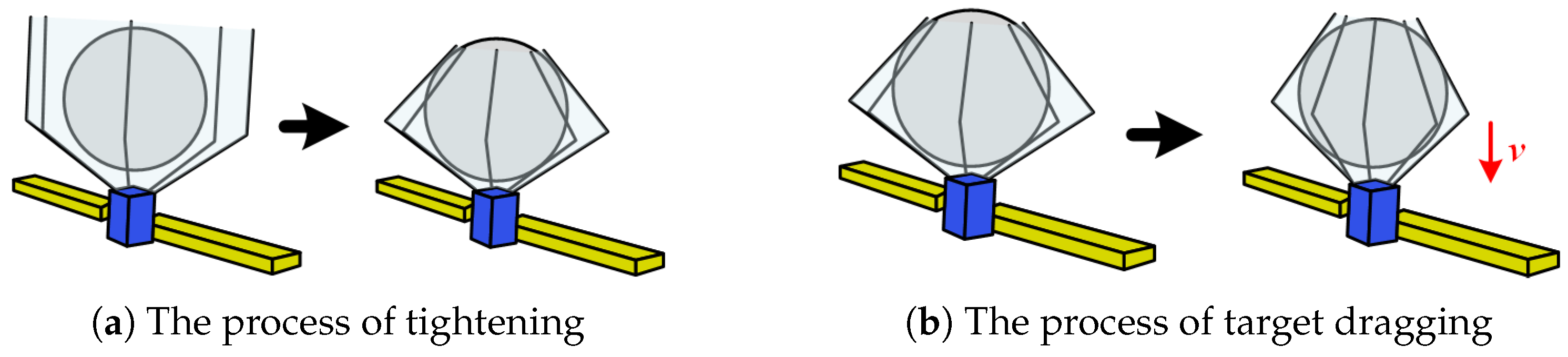
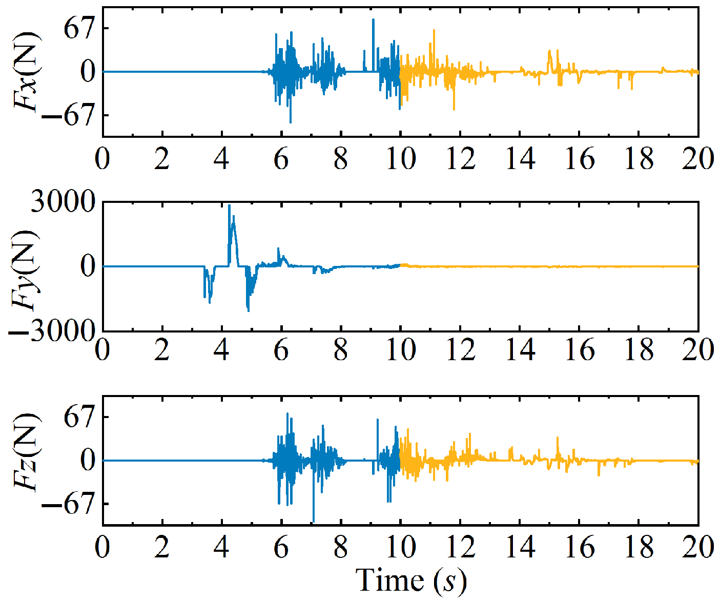
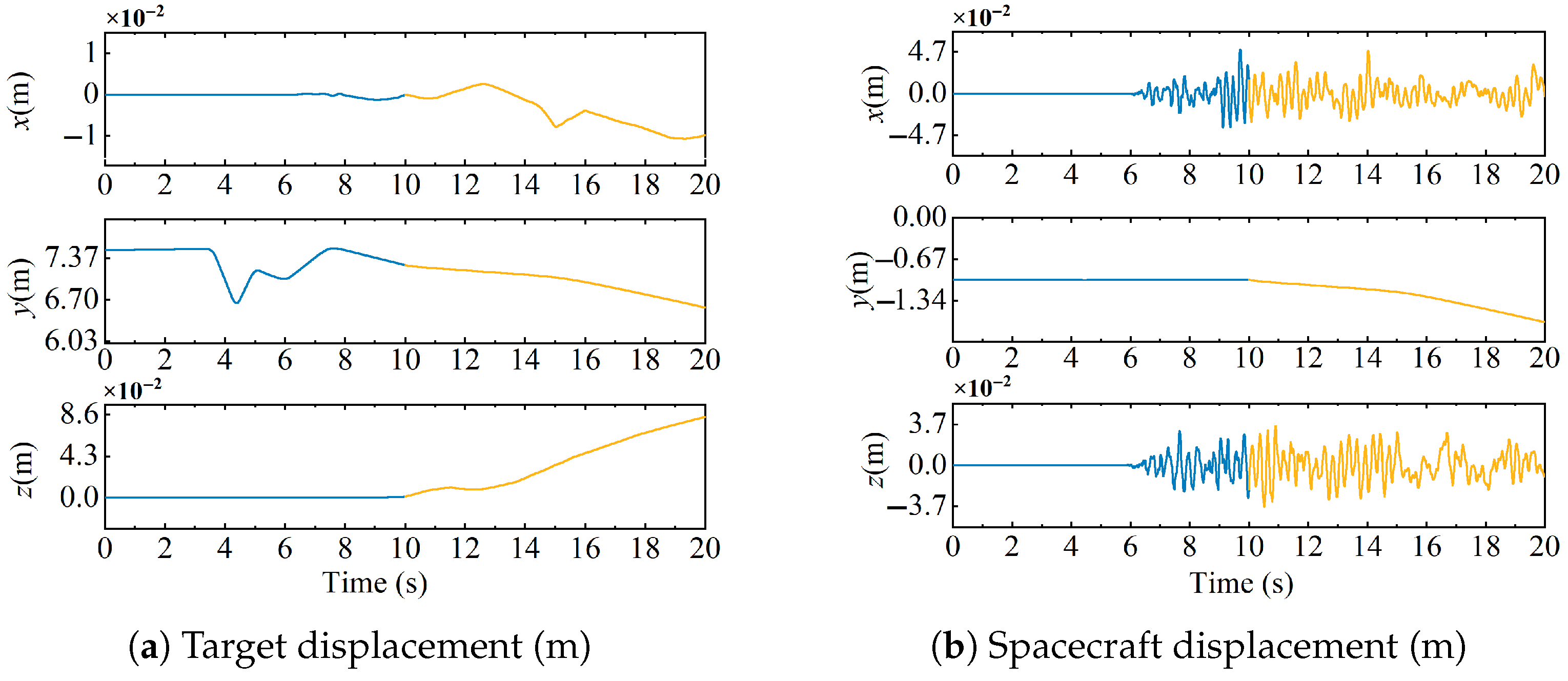
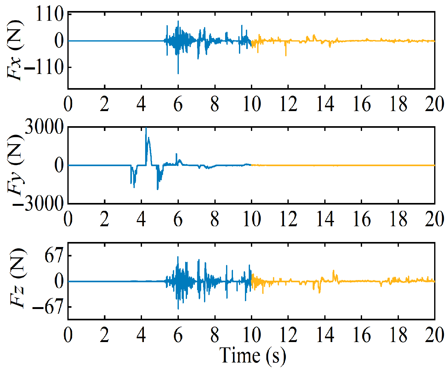
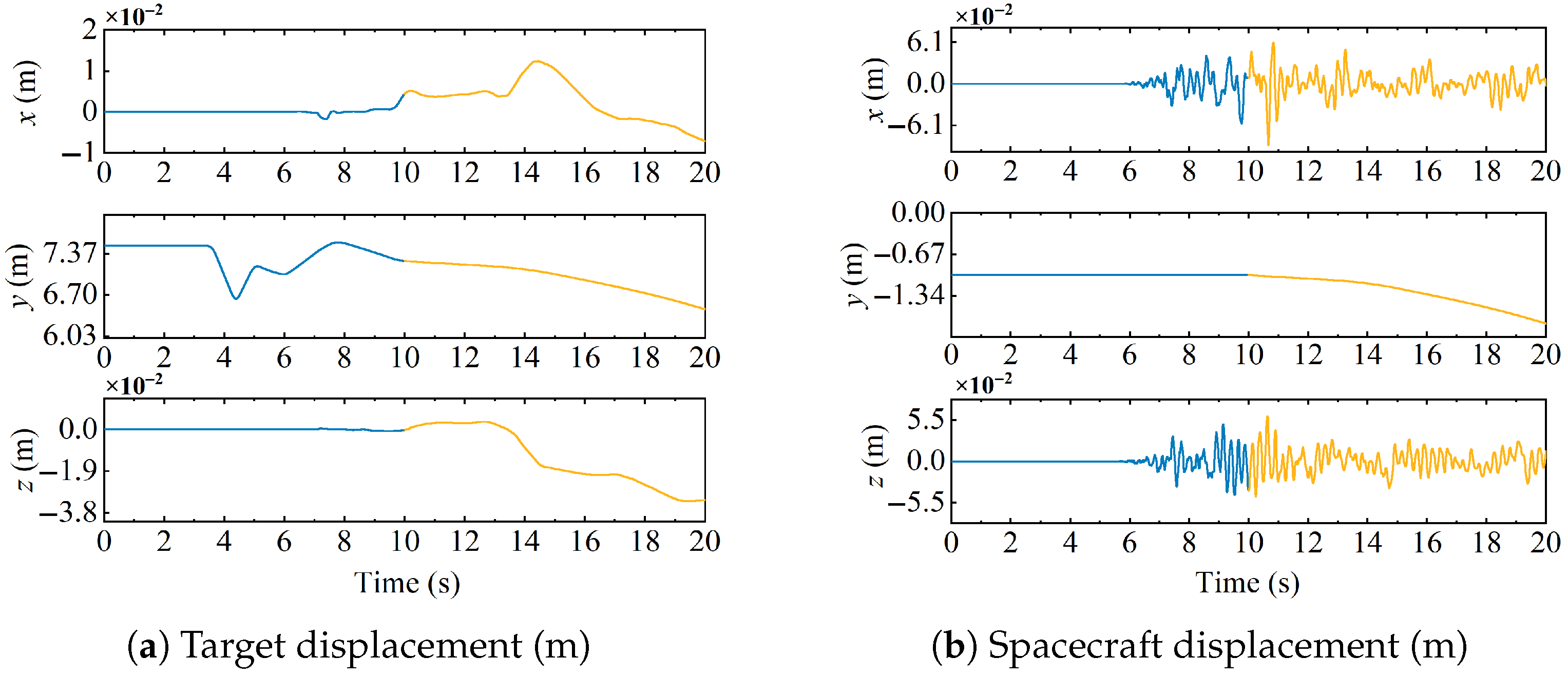
For targets in escape and rotating states, the spacecraft’s attitude variation is less than 10 2 deg throughout the capture process, demonstrating that the proposed control method can ensure the spacecraft’s attitude stability during capture. During the capture phase, the spacecraft’s position does not experience significant deviation under the influence of the collision force, proving that the method can effectively compensate for disturbances from instantaneous impacts. In the towing phase, the target’s center of mass moves with the spacecraft, and the collision force amplitude is less than 100 N, while the spacecraft’s position and attitude amplitudes are less than 10 2 m and 10 2 deg, demonstrating that the target and spacecraft’s position and attitude are in a relatively stable state after capture, thus proving that the method can achieve stable capture of moving targets.
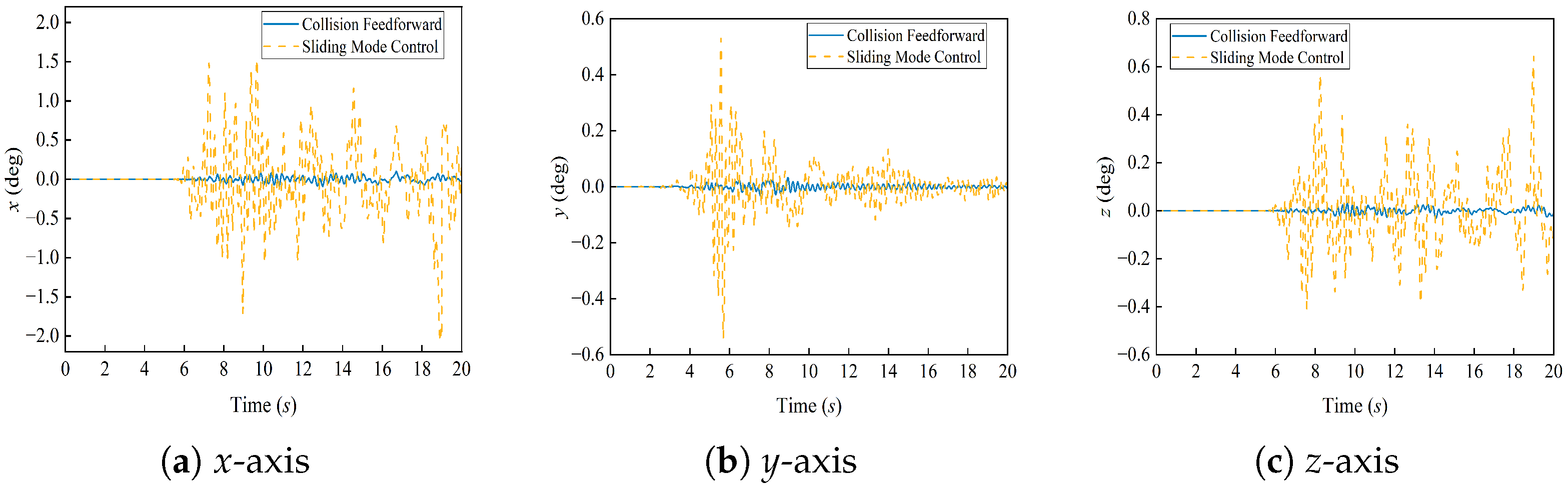
(2)
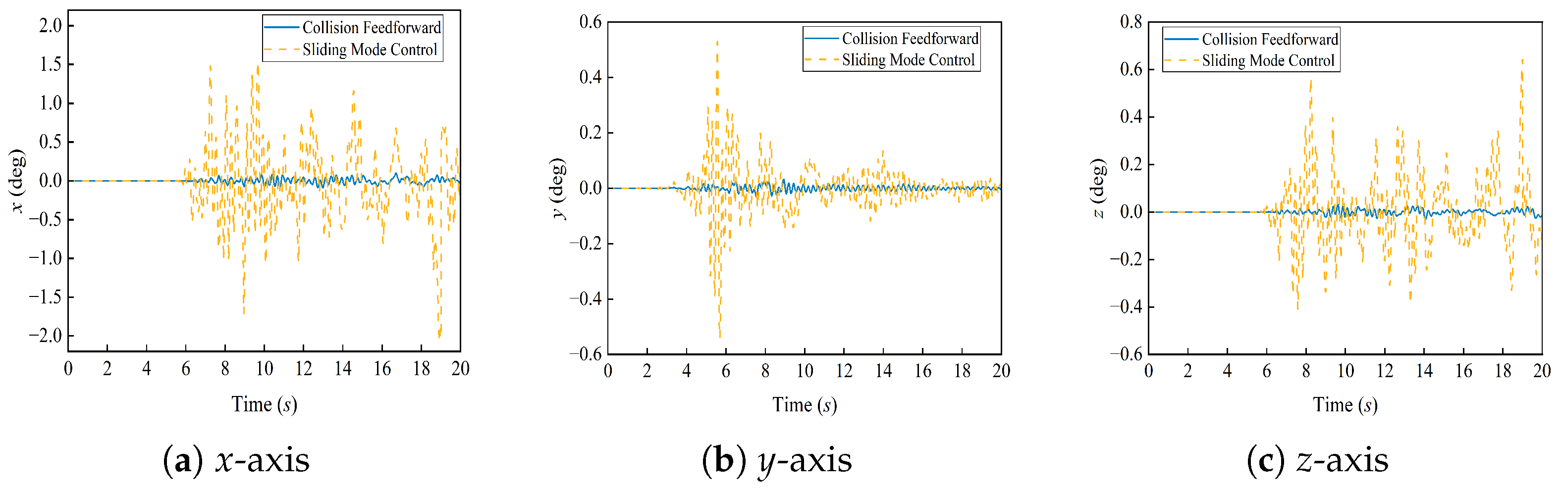
The simulation results indicate that, during the target capture stage, the attitude change amplitude at the moment of impact is reduced by a factor of ten compared to the standard sliding mode control. This demonstrates that the model-based collision estimation feedforward control effectively mitigates the transient impact disturbances caused by the collision event. Furthermore, during the towing phase, the designed controller successfully maintains the spacecraft’s position and attitude jitter within a range of 10 2 , thus confirming that our control method significantly enhances attitude stability during the capture of spherical debris. These findings validate the effectiveness of our approach.
Overall, the proposed method can effectively achieve the capture of moving targets while reducing attitude disturbances from instantaneous impacts during capture. It also offers a certain improvement in control precision compared to traditional standard sliding mode control, demonstrating its advantages. Nevertheless, the method has some limitations. Our current analysis is primarily focused on spherical debris capture. Future work will extend the analysis and research to encompass the capture of non-spherical space debris exhibiting complex, mixed motion. This will enhance the reliability and versatility of space net systems for broader engineering applications.

Author Contributions

Formal analysis, J.Y. and W.L.; investigation, W.W.; methodology, H.Z. and Z.H.; supervision, Y.Z.; writing—original draft, W.W.; writing—review & editing, W.W. and C.T. All authors have read and agreed to the published version of this manuscript.

Funding

This work was financially supported by the National Natural Science Foundation of China (number U21B2075), the National Natural Science Foundation of China (number 52475249), the National Key R&D Program of China (number 2023YFC2205900, 2023YFC2205903, 2023YFC2205904), the Reusable Space Debris Capture and Removal Project (number KJSP2020010302), the Stable Supporting Fund of the National Key Laboratory of Underwater Acoustic Technology (number JCKYS2023604SSJS012), and the Fundamental Research Funds for the Central Universities (number 3072023WD070101).

Institutional Review Board Statement

Not applicable.

Informed Consent Statement

Not applicable.

Data Availability Statement

The original contributions presented in the study are included in the article, further inquiries can be directed to the corresponding author.

Acknowledgments

We would like to thank the Harbin Engineering University and Beijing Institute of Astronautical System Engineering for their financial and equipment support for this project.

Conflicts of Interest

The authors declare no conflicts of interest.

Abbreviations

Equation notations table:
NotationsNotations explanation
M Mass matrix
e Generalized coordinates
r Position vector
S n Shape function
E Strain tensor
C Elastic tensor
Q Generalized force
λ Lagrange multiplier
K c Contact stiffness coefficient
C c Contact damping coefficient;
δ n Normal penetration depth
RRadius of curvature
ω e Deviation angular velocity
sigSign function
k i Sliding surface coefficients
q d Desired quaternion
q e Deviation quaternion
α i Sign function coefficients
δ Dirichlet function
IIdentity matrix
tTime
J Spacecraft inertia
A ( q q ) Attitude rotation matrix
G Known state of the system,
D Unknown state of the system
u Spacecraft control torque
β i , γ i , η observation gains
ζ i , o i Sign function coefficients
Γ Prediction coefficient

References

  1. Adilov, N.; Braun, V.; Alexander, P.; Cunningham, B. An estimate of expected economic losses from satellite collisions with orbital debris. J. Space Saf. Eng. 2023, 10, 66–69. [Google Scholar] [CrossRef]
  2. Raina, D.; Gora, S.; Maheshwari, D.; Shah, S.V. Impact modeling and reactionless control for post-capturing and maneuvering of orbiting objects using a multi-arm space robot. Acta Astronaut. 2021, 182, 21–36. [Google Scholar] [CrossRef]
  3. Dal, P.N.; Shah, S.V. Joint acceleration based adaptive reactionless manipulation of closed-loop multi-arm space robot in post-capture phase. Acta Astronaut. 2025, 226, 439–457. [Google Scholar] [CrossRef]
  4. Yu, B.; Wen, H.; Jin, D. Review of deployment technology for tethered satellite systems. Acta Mech. Sin. 2018, 34, 755–768. [Google Scholar] [CrossRef]
  5. Zhao, Y.; Huang, P.; Zhang, F. Dynamic modeling and super-twisting sliding mode control for tethered space robot. Acta Astronaut. 2018, 143, 310–321. [Google Scholar] [CrossRef]
  6. Jang, M.; Shin, H.C.; Sim, C.H. Active debris removal simulations using spider-web space-nets for KITSAT-1 satellite. Int. J. Aeronaut. Space Sci. 2023, 24, 1311–1322. [Google Scholar] [CrossRef]
  7. Wang, B.; Meng, Z.; Jia, C.; Huang, P. Anti-tangle control of tethered space robots using linear motion of tether offset. Aerosp. Sci. Technol. 2019, 89, 164–174. [Google Scholar] [CrossRef]
  8. Endo, Y.; Kojima, H.; Trivailo, P.M. New formulation for evaluating status of space debris capture using tether-net. Adv. Space Res. 2022, 70, 2976–3002. [Google Scholar] [CrossRef]
  9. Juillard, M.; Kneib, J. Simulation tool: Resources management in high performance avionic for ADR missions. In Proceedings of the 2021 IEEE Aerospace Conference, Big Sky, MT, USA, 6–13 March 2021. [Google Scholar]
  10. Biesbroek, R.; Aziz, S.; Wolahan, A.; Cipolla, S.F.; Richard-Noca, M.; Piguet, L. The Clearspace-1 mission: ESA and clearspace team up to remove debris. In Proceedings of the 8th European Conference on Space Debris (Virtual), Darmstadt, Germany, 20–23 April 2021. [Google Scholar]
  11. Tang, C.; Deng, Y.Q.; Bai, Z.F.; Wei, C.; Zhao, Y. Dynamics analysis of space netted pocket system capturing non-cooperative target. Appl. Sci. 2023, 13, 10377. [Google Scholar] [CrossRef]
  12. Wang, R.; Liu, X.; Ji, R.; Cai, G.; Xu, F. Compliance resistance collision control for operating a space robot to capture a non-cooperative spacecraft. Aerosp. Sci. Technol. 2024, 153, 109425. [Google Scholar] [CrossRef]
  13. Peng, Z.; Wang, C. Reinforcement Learning-Based Pose Coordination Planning Capture Strategy for Space Non-Cooperative Targets. Aerospace 2024, 11, 706. [Google Scholar] [CrossRef]
  14. Wang, J.; Zhang, H.; Wang, W.; Qi, C.; Xu, J.; Zhao, Y.; Ma, C.; Tian, J. Research on Spatial Developable Mechanism Considering Revolute Clearance Joints with Irregular Rough Surfaces. Actuators 2024, 13, 274. [Google Scholar] [CrossRef]
  15. Qi, C.; Peng, S.; Zhang, H.; Li, W.; Dai, S.; Luo, M. Hybrid model of deep learning and contact theory for predicting distributed contact force in space debris de-tumbling. Measurement 2025, 253, 117767. [Google Scholar] [CrossRef]
  16. Zhang, H.; Guo, J.; Liu, J.; Ren, G. An efficient multibody dynamic model of arresting cable systems based on ALE formulation. Mech. Mach. Theory 2020, 151, 103892. [Google Scholar] [CrossRef]
  17. Shan, M.; Guo, J.; Gill, E. An analysis of the flexibility modeling of a net for space debris removal. ScienceDirect 2020, 65, 1084–1094. [Google Scholar] [CrossRef]
  18. Chang, R.; Jia, Q.; Chu, M. Stabilization control for spacecraft-manipulator system after capturing tumbling target. Int. J. Control Autom. Syst. 2022, 20, 3706–3717. [Google Scholar] [CrossRef]
  19. Zhao, Y.; Zhang, F.; Huang, P. Capture dynamics and control of tethered space net robot for space debris capturing in unideal capture case. J. Frankl. Inst. 2020, 357, 12019–12036. [Google Scholar] [CrossRef]
  20. Zhao, Y.; Huang, P.; Zhang, F. Contact dynamic modeling and control for tethered space net robot with asymmetric net configuration. IEEE Trans. Aerosp. Electron. Syst. 2019, 55, 918–929. [Google Scholar] [CrossRef]
  21. Zhao, Y.; Zhang, F.; Huang, P.; Liu, X. Impulsive super-twisting sliding mode control for space debris capturing via tethered space net robot. IEEE Trans. Ind. Electron. 2020, 67, 6875–6882. [Google Scholar] [CrossRef]
  22. Zhang, Y.; Feng, R.; Yu, Y.; Liu, J.; Baoyin, H. Asteroid capture dynamics and control using a large-scale flexible net. IEEE Trans. Aerosp. Electron. Syst. 2022, 58, 4034–4043. [Google Scholar] [CrossRef]
  23. Han, D.; Liu, Z.; Huang, P. Capture and detumble of a non-cooperative target without a specific gripping point by a dual-arm space robot. ScienceDirect 2022, 69, 3770–3784. [Google Scholar] [CrossRef]
  24. Yang, Z.; Liu, C.; Yue, X. NI-based static output feedback control for attitude stabilization of post-capture flexible spacecraft. Adv. Space Res. 2023, 71, 3681–3695. [Google Scholar] [CrossRef]
  25. Tang, C.; Yao, J.M.; Liang, L.; Zhang, H.; Wei, C.; Zhao, Y. IEstimation of full dynamic parameters of large space debris based on rope net flexible collision and vision. Actuators 2023, 12, 344. [Google Scholar] [CrossRef]
  26. Anjum, M.; Khan, Q.; Ullah, S.; Hafeez, G.; Fida, A.; Iqbal, J.; Albogamy, F.R. Maximum power extraction from a standalone photo voltaic system via neuro-adaptive arbitrary order sliding mode control strategy with high gain differentiation. Appl. Sci. 2022, 12, 2773. [Google Scholar] [CrossRef]
  27. Hong, Y.; Huang, J.; Xu, Y. On an output feedback finite-time stabilization problem. IEEE Trans. Autom. Control 2001, 46, 306–309. [Google Scholar]
  28. Zhang, L.; Xia, Y.; Shen, G.; Cui, B. Fixed-time attitude tracking control for spacecraft based on a fixed-time extended state observer. Sci. China Inf. Sci. 2021, 64, 150–166. [Google Scholar] [CrossRef]
  29. Huang, Z.; Tang, C.; Yu, Q.; Khaliel, M.S.S.; Wei, C. Dynamics and FNTSM control of spacecraft with a film capture pocket system. Space Sci. Technol. 2024, 3, 79. [Google Scholar] [CrossRef]
  30. Qi, R.; Zhang, Y.; Jiang, H.; Zhong, R. Dynamic analysis of tethered defunct satellites with solar panels. Astrodynamics 2024, 8, 297–309. [Google Scholar] [CrossRef]
  31. Kucharski, D.; Kirchner, G.; Koidl, F.; Fan, C.; Carman, R.; Moore, C.; Dmytrotsa, A.; Ploner, M.; Bianco, G.; Medvedskij, M.; et al. Attitude and spin period of space debris envisat measured by satellite laser ranging. IEEE Trans. Geosci. Remote Sens. 2014, 52, 7651–7657. [Google Scholar] [CrossRef]
  32. Anz-Meador, P.; Opiela, J.; Shoots, D.; Liou, J.-C. History of On-Orbit Satellite Fragmentations, 15th ed.; NASA Orbital Debris Program Office: Houston, TX, USA, 2018; pp. 1–10. [Google Scholar]
Figure 1. Space netted pocket capture system.
Actuators 14 00358 g001
Figure 2. Structure composition and size of the netted pocket system.
Actuators 14 00358 g002
Figure 3. Equivalent plate-shell element.
Actuators 14 00358 g003
Figure 4. Flexible netted pocket encirclement capture full process.
Actuators 14 00358 g004
Figure 5. Model collision feedforward–sliding mode control feedback hybrid controller.
Actuators 14 00358 g005
Figure 6. The collision force when the target escape velocity is 5 mm/s.
Actuators 14 00358 g006
Figure 7. The displacement when the target escape velocity is 5 mm/s.
Actuators 14 00358 g007
Figure 8. Comparison of spacecraft attitude under different control methods.
Actuators 14 00358 g008
Figure 9. The collision force when the target rotation velocity is 2 deg/s.
Actuators 14 00358 g009
Figure 10. The displacement when the target rotation velocity is 2 deg/s.
Actuators 14 00358 g010
Figure 11. Comparison of spacecraft attitude under different control methods.
Actuators 14 00358 g011
Table 1. Control system parameters.
Controller NameParameters
Feedforward controller K = [1,1,1]
Sliding mode controller parameters k 1 = 10, k 2 = 2, α 1 = 11/5, α 2 = 11/19, β 1 = 4, β 2 = 2, γ 2 = 7.5, η = 15
Extended observer parameters o 1 = 0.99, ζ = 1.01, α 3 = 11/5, α 4 = 11/19
Disclaimer/Publisher’s Note: The statements, opinions and data contained in all publications are solely those of the individual author(s) and contributor(s) and not of MDPI and/or the editor(s). MDPI and/or the editor(s) disclaim responsibility for any injury to people or property resulting from any ideas, methods, instructions or products referred to in the content.

