
Recent Advances in Bidirectional Converters and Regenerative Braking Systems in Electric Vehicles


Abstract
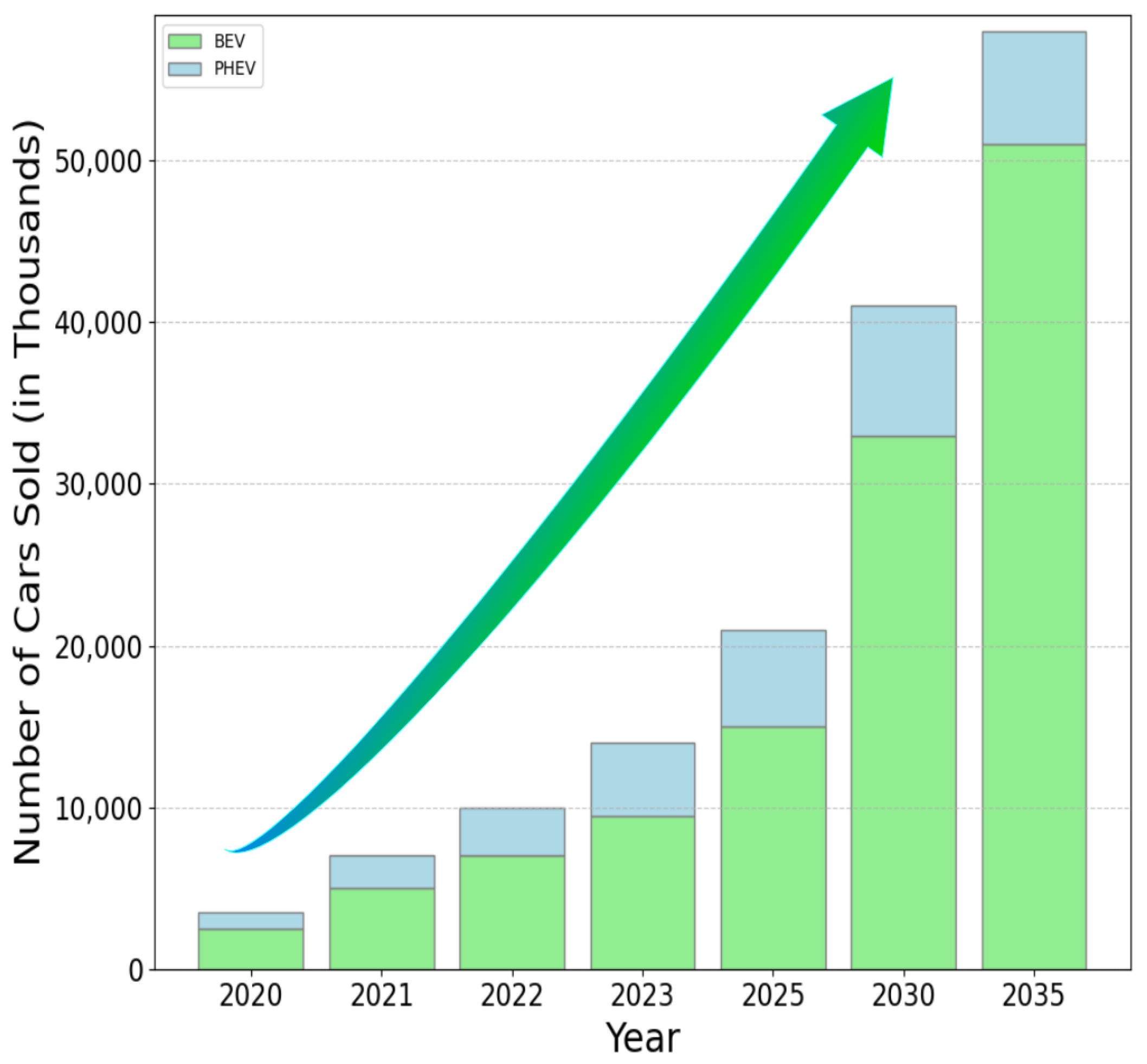
1. Introduction
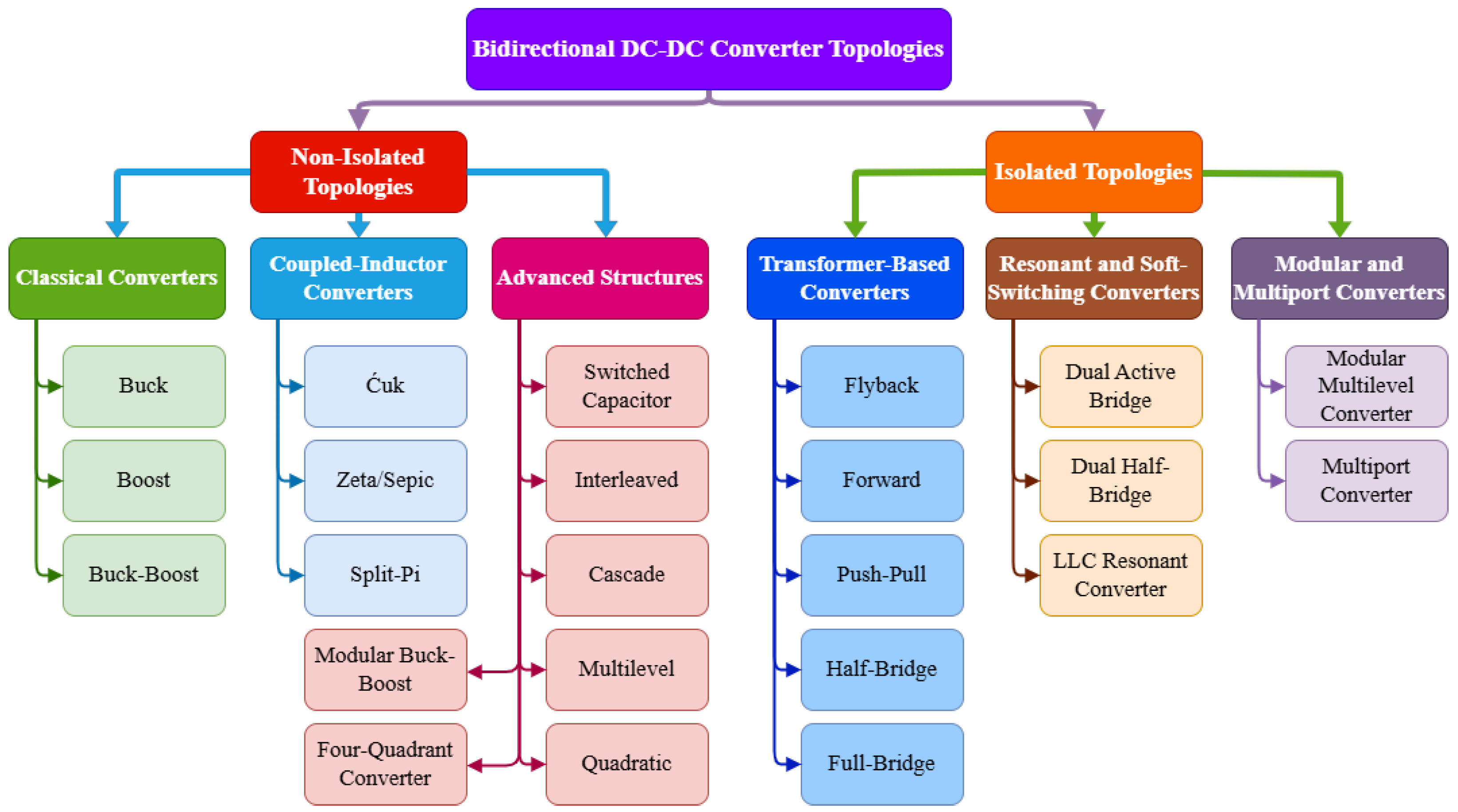
2. Bidirectional DC-DC Converter Topologies
2.1. Non-Isolated Topologies
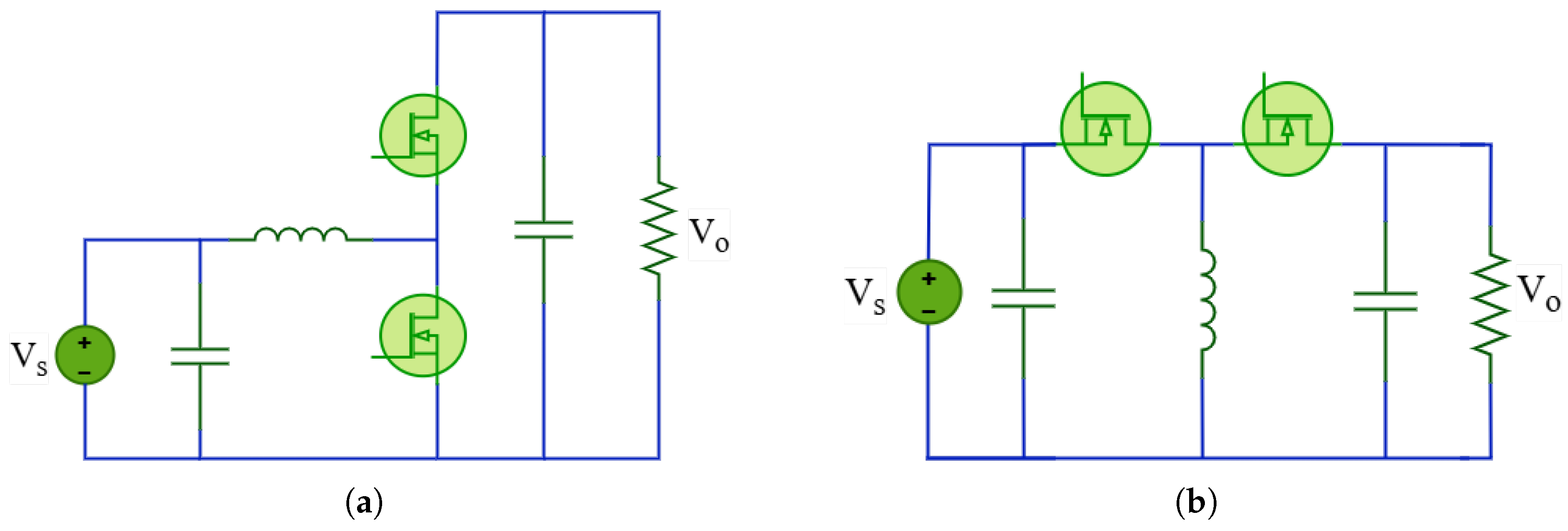
2.1.1. Buck, Boost, and Buck-Boost Derived Converters
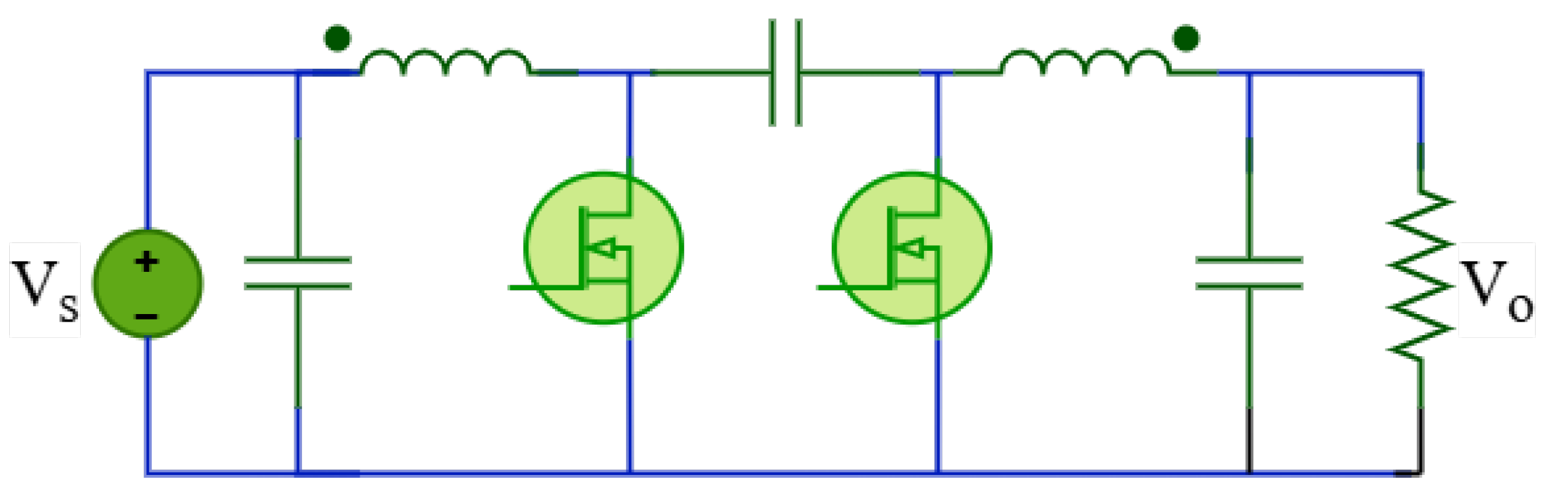
2.1.2. Ćuk Converter
2.1.3. Zeta/Sepic Converters
2.1.4. Cascaded Converters
2.1.5. Switched-Capacitor Converters
2.1.6. Interleaved Topology
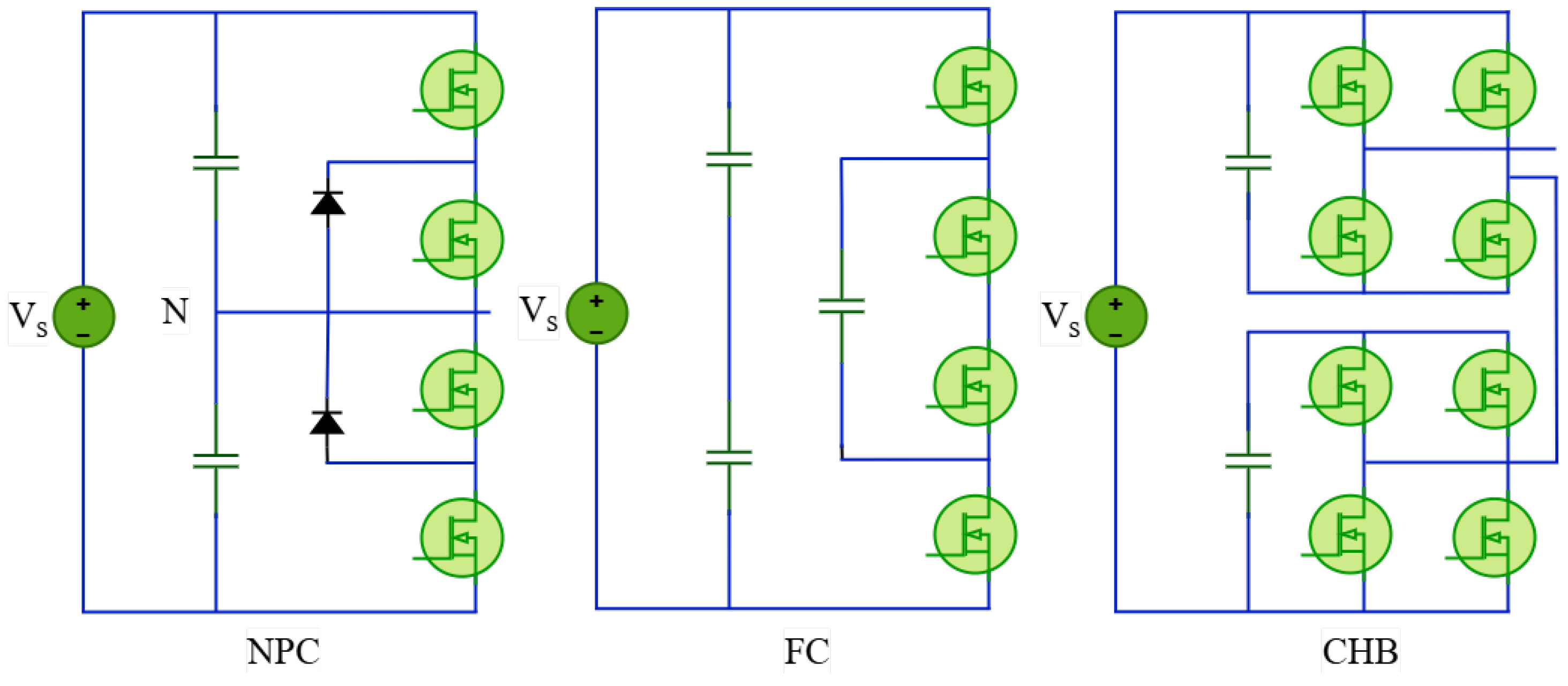
2.1.7. Multilevel Converter
2.2. Isolated Topologies
2.2.1. Flyback Converter
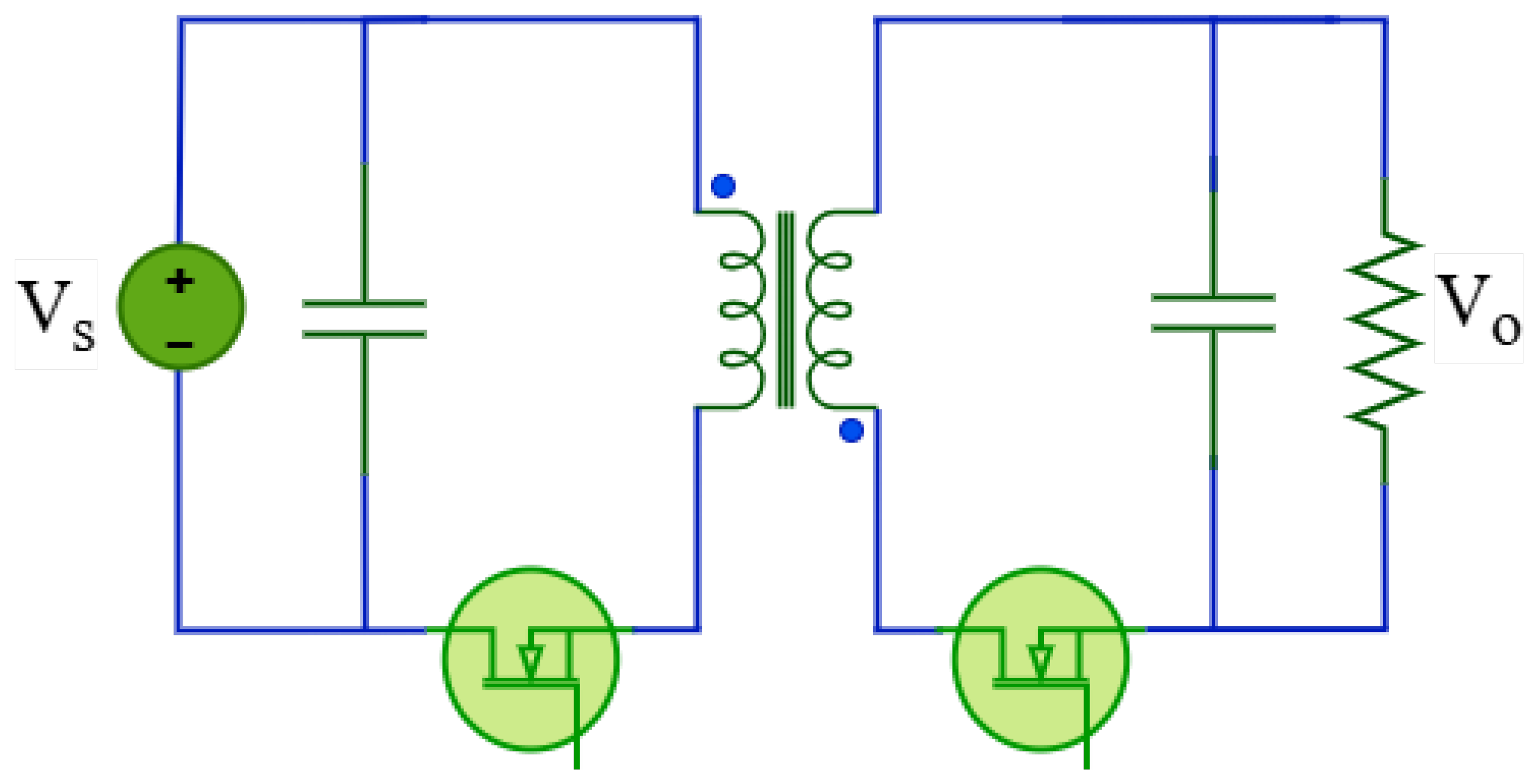
2.2.2. Push–Pull Converter
2.2.3. Forward Converter
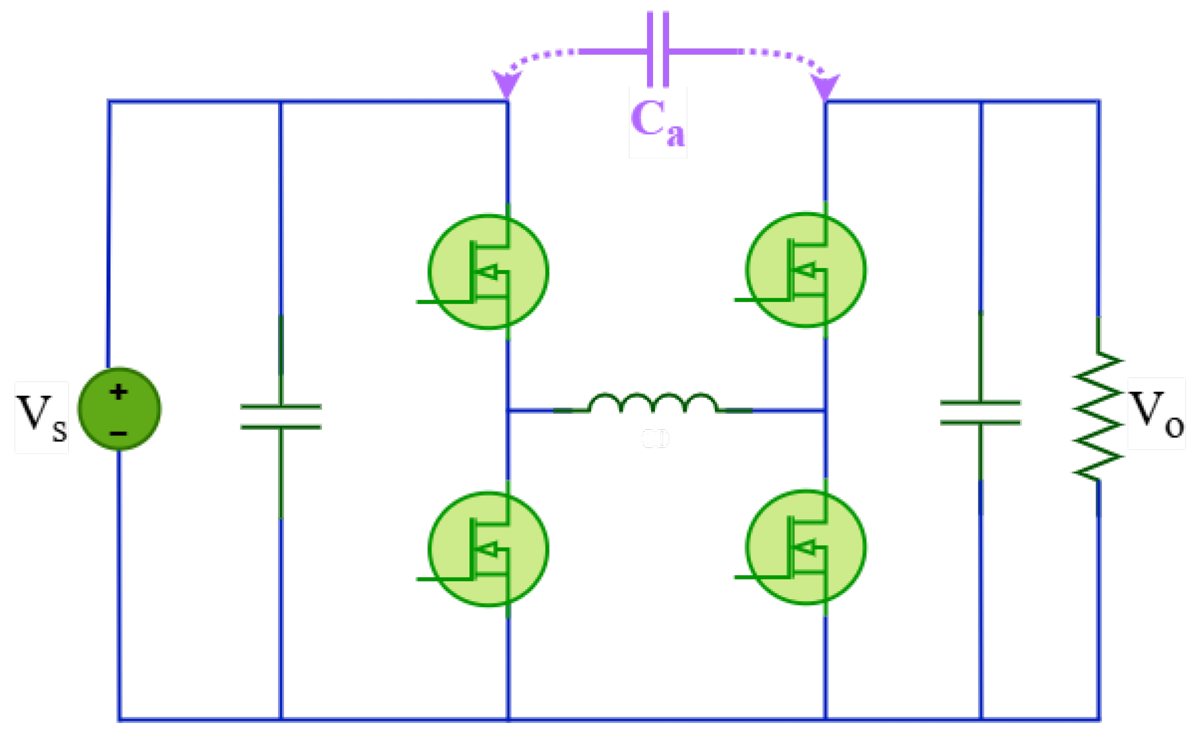
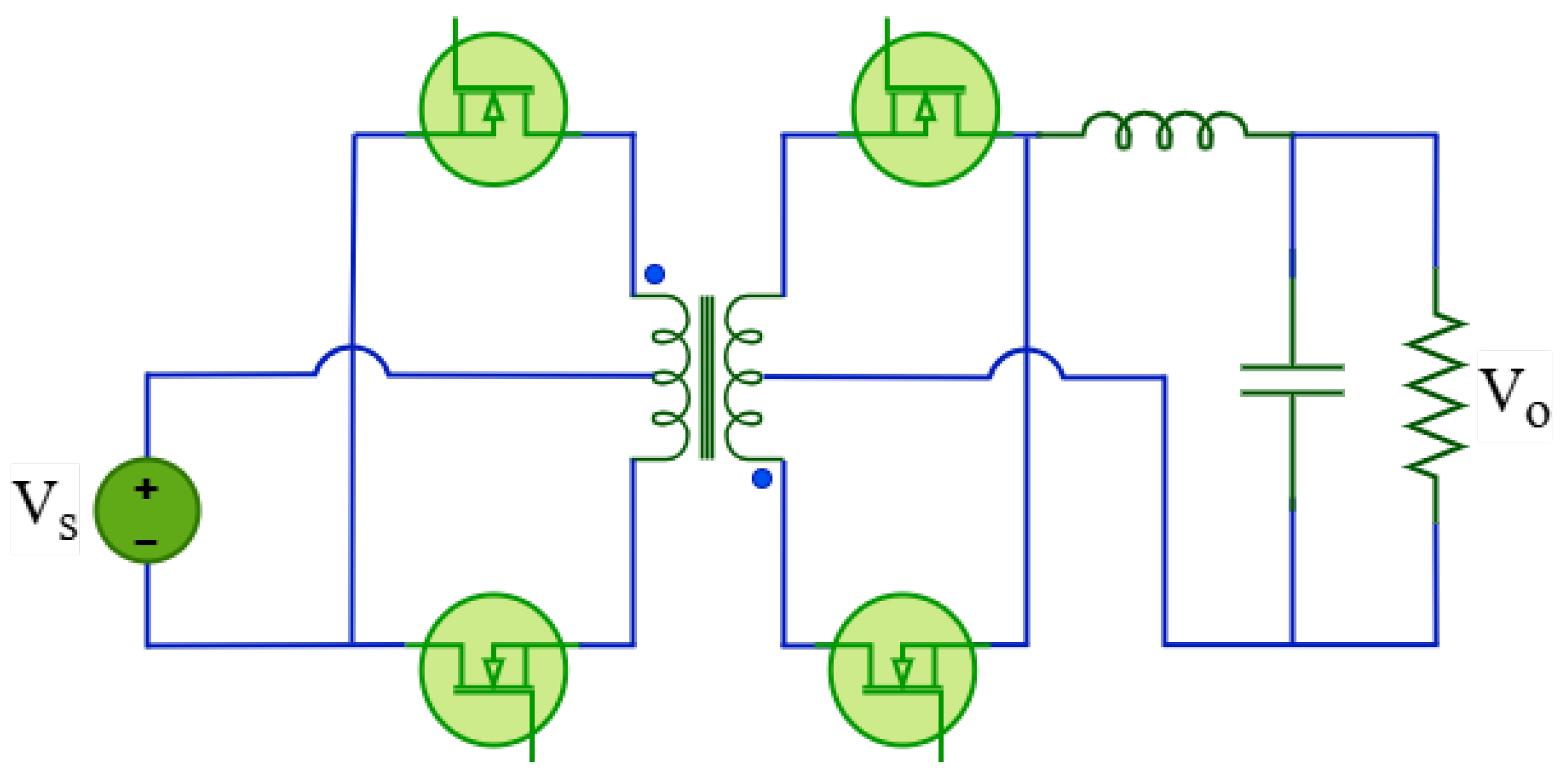
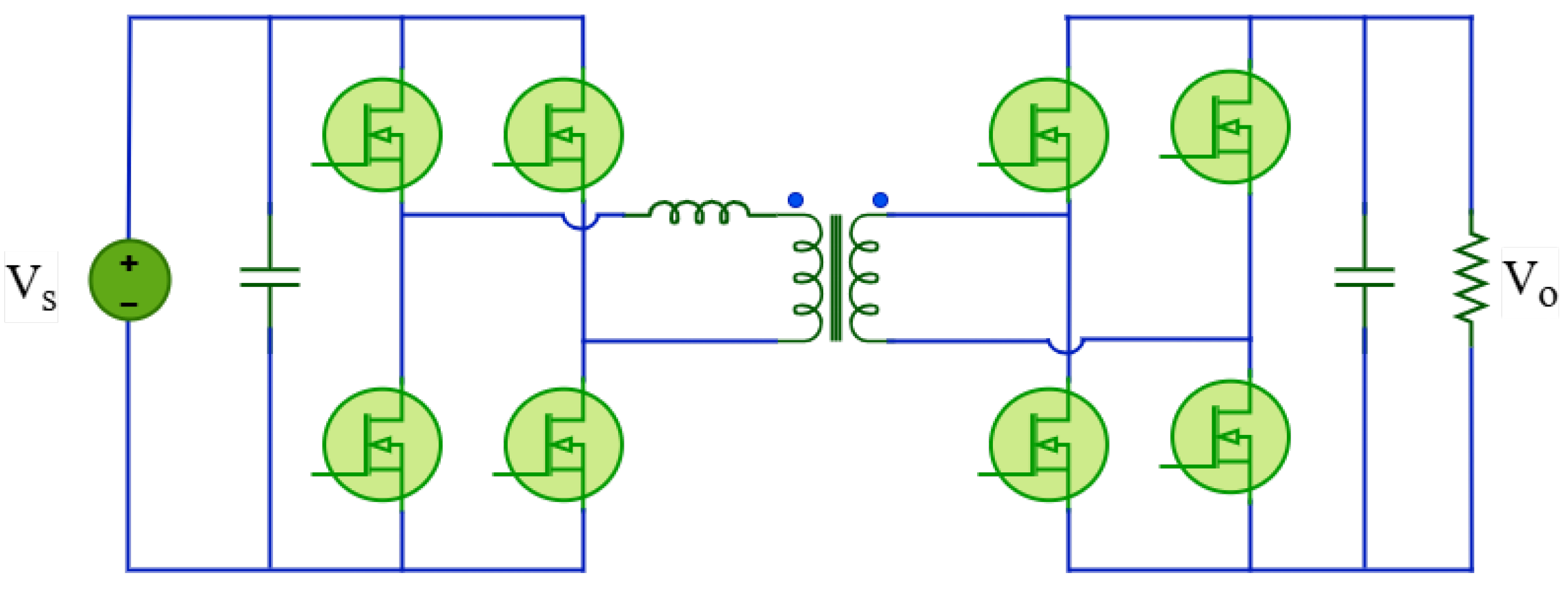
2.2.4. Dual Active Bridge (DAB) Converter
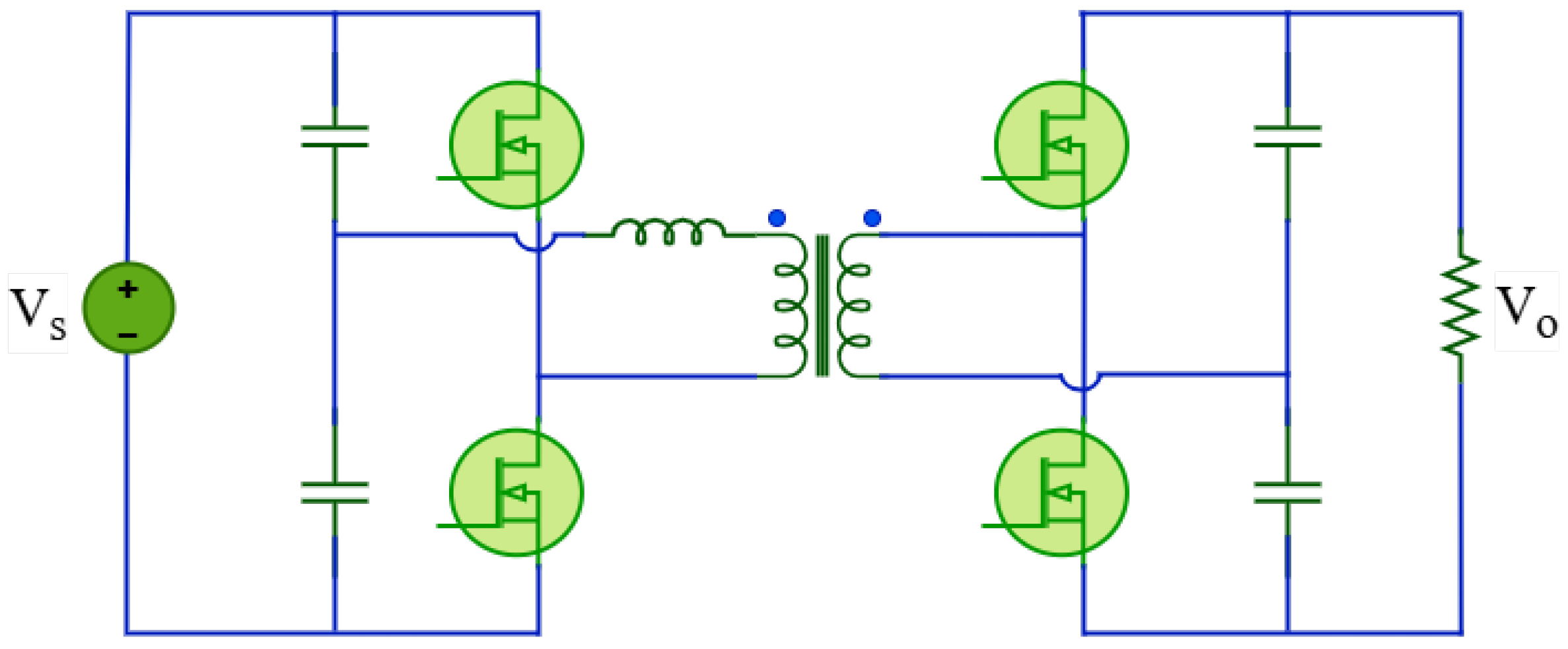
2.2.5. Dual Half-Bridge Converter
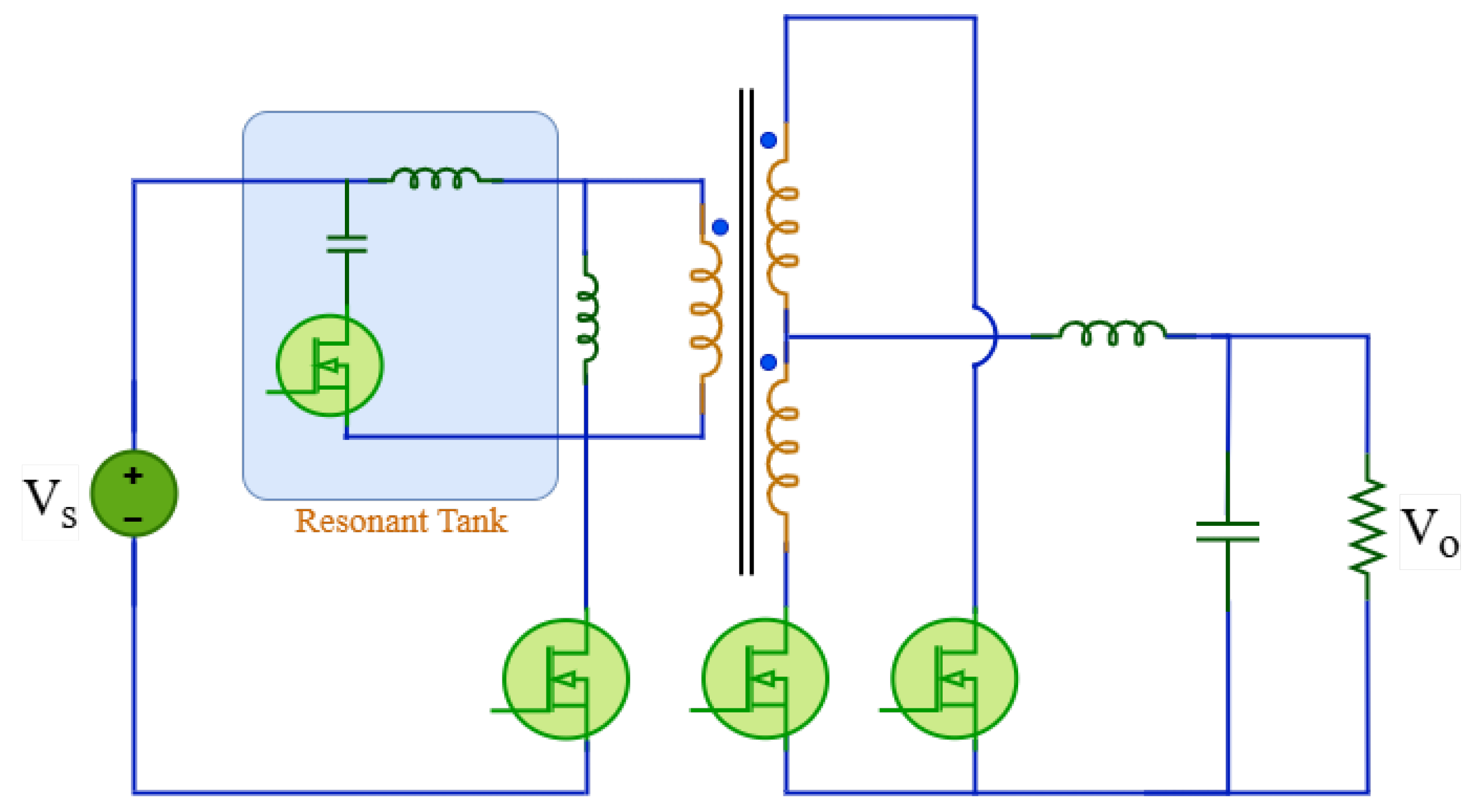
2.2.6. LLC Resonant Converter
2.2.7. Multilevel Bidirectional Converter
3. Regenerative Braking Systems
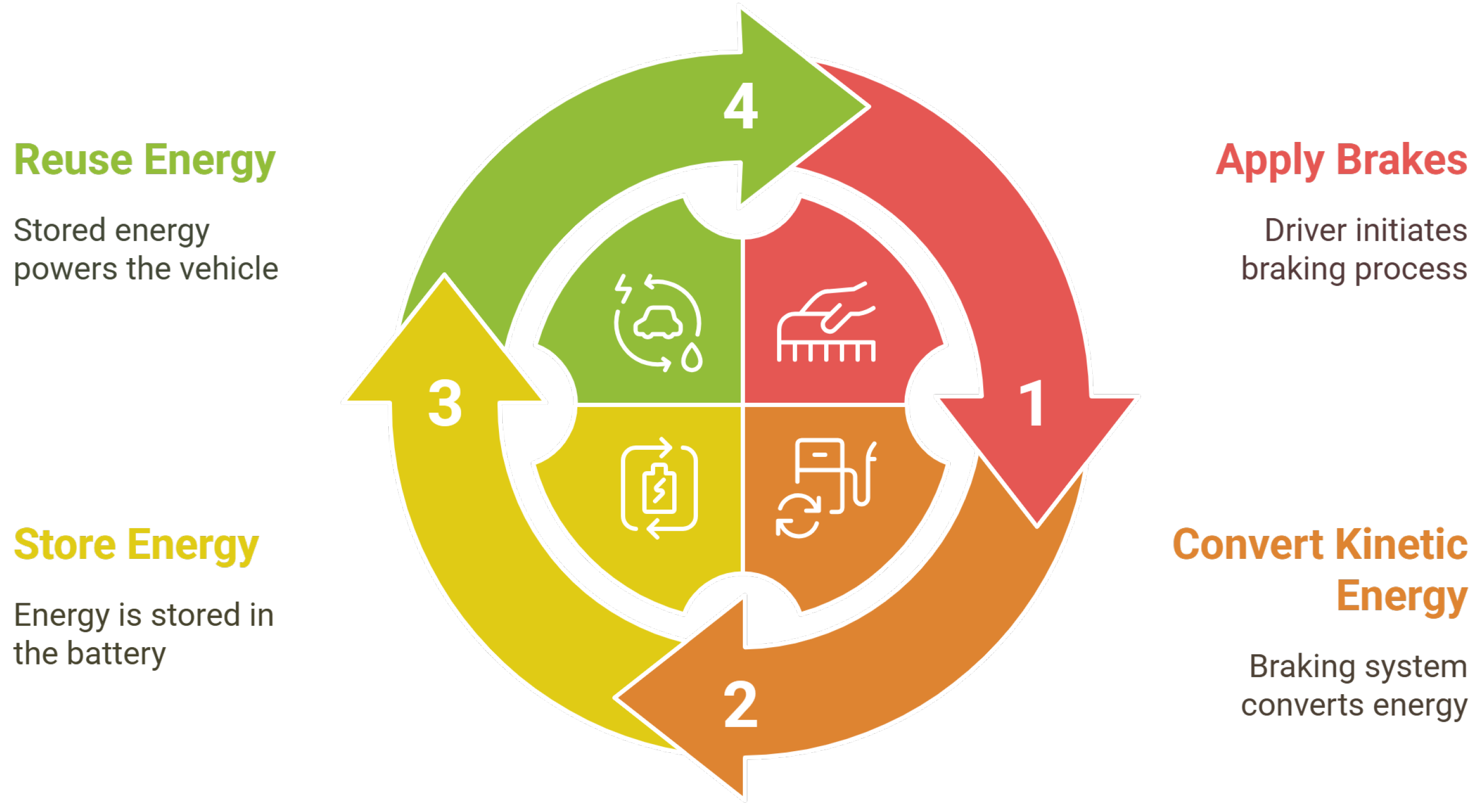
3.1. Principles and Components
3.1.1. Effectiveness Across Electric Vehicle Types
3.1.2. Energy Conversion and Storage Mechanisms
3.1.3. Types of Energy Storage for Regenerative Braking
Batteries
Supercapacitors
Hybrid Energy Storage Systems (HESSs)
Flywheel Energy Storage Systems (FESSs)
3.1.4. Role of Electric Motors and Power Electronics
3.2. Control Strategies
3.2.1. Fuzzy Logic Control
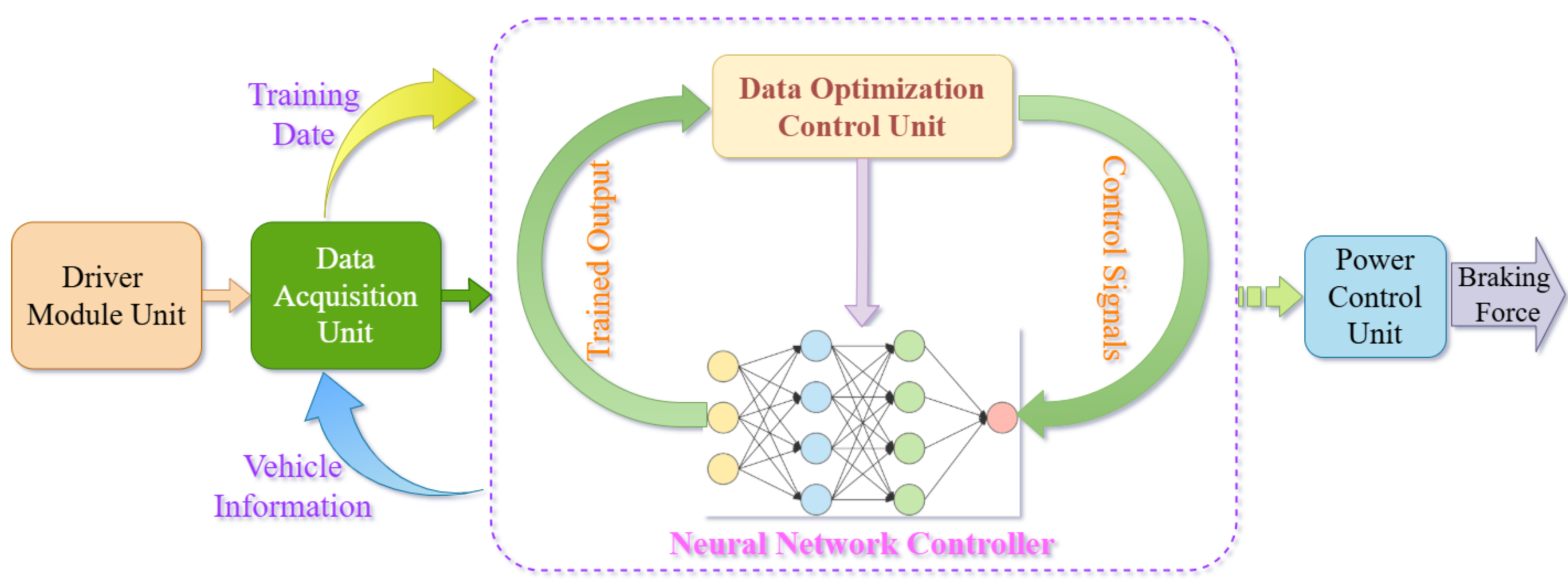
3.2.2. Neural Network-Based Control
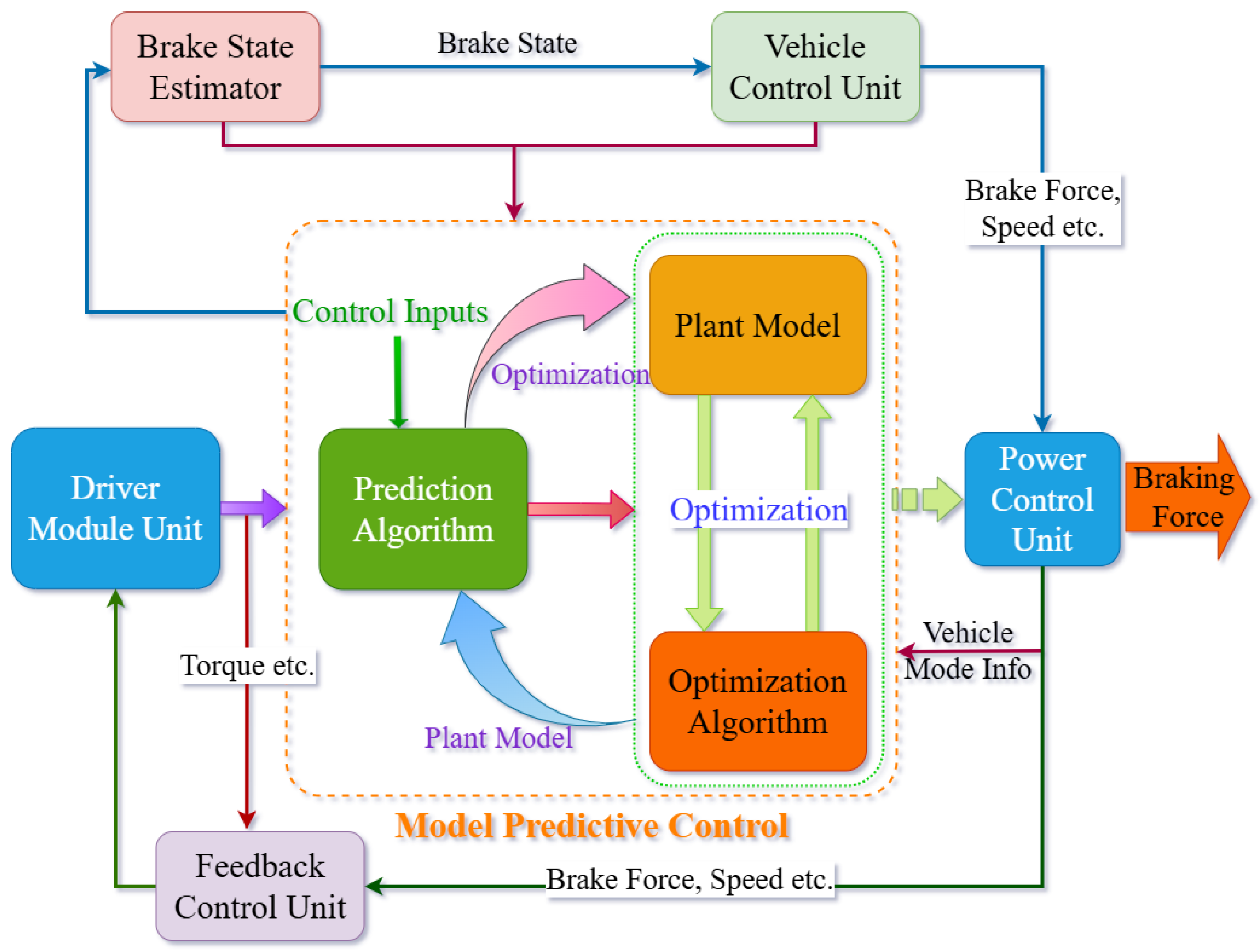
3.2.3. Model Predictive Control
3.2.4. Sliding Mode Control

3.2.5. Other Control Techniques
3.3. Impact on Battery Life
3.3.1. Effects of Regenerative Braking on Battery Degradation
3.3.2. Strategies to Mitigate Battery Wear
4. Emerging Trends and Future Directions
4.1. Advanced Materials and Technologies
4.1.1. Wide-Bandgap Semiconductors (SiC, GaN)
Silicon Carbide (SiC) Devices
Gallium Nitride (GaN) Devices
4.1.2. High-Efficiency Motor Designs
4.2. AI-Based Control Systems
4.3. Integration with Autonomous Driving
5. Conclusions
Author Contributions
Funding
Conflicts of Interest
References
- Felter, K. The US and The UN Framework Convention on Climate Change (UNFCCC); Harvard Model Congress: Cambridge, MA, USA, 2023. [Google Scholar]
- Hou, M.Z.; Luo, J.; Huang, L.; Beck, H.P.; Mehmood, F.; Wang, Q.; Wu, X.; Wu, L.; Yue, Y.; Fang, Y.; et al. Strategies toward carbon neutrality: Comparative analysis of China, USA, and Germany. Carbon Neutral Syst. 2025, 1, 3. [Google Scholar] [CrossRef]
- Department for Transport; Alexander, H. Phasing Out the Sale of New Petrol and Diesel Cars from 2030 and Support for Zero Emission Vehicle (ZEV) Transition. Written Statement to Parliament, House of Commons; 2025. Available online: https://www.gov.uk/government/speeches/phasing-out-the-sale-of-new-petrol-and-diesel-cars-from-2030-and-support-for-zero-emission-vehicle-zev-transition (accessed on 23 April 2025).
- Blaabjerg, F.; Wang, H.; Vernica, I.; Liu, B.; Davari, P. Reliability of power electronic systems for EV/HEV applications. Proc. IEEE 2020, 109, 1060–1076. [Google Scholar] [CrossRef]
- Naseem, H.; Seok, J.K. Reactive Power Controller for Single Phase Dual Active Bridge DC–DC Converters. IEEE Access 2023, 11, 141537–141546. [Google Scholar] [CrossRef]
- Panchanathan, S.; Vishnuram, P.; Rajamanickam, N.; Bajaj, M.; Blazek, V.; Prokop, L.; Misak, S. A comprehensive review of the bidirectional converter topologies for the vehicle-to-grid system. Energies 2023, 16, 2503. [Google Scholar] [CrossRef]
- International Energy Agency. Global EV Data Explorer. 2025. Available online: https://www.iea.org/data-and-statistics/data-tools/global-ev-data-explorer (accessed on 23 April 2025).
- Dias, N.; Naik, A.J.; Shet, V.N. A Novel Tri-Mode Bidirectional DC–DC Converter for Enhancing Regenerative Braking Efficiency and Speed Control in Electric Vehicles. World Electr. Veh. J. 2024, 15, 12. [Google Scholar] [CrossRef]
- Bahrami, A. EV charging definitions, modes, levels, communication protocols and applied standards. Changes 2020, 1, 1–10. [Google Scholar]
- Aghabali, I.; Bauman, J.; Kollmeyer, P.J.; Wang, Y.; Bilgin, B.; Emadi, A. 800-V electric vehicle powertrains: Review and analysis of benefits, challenges, and future trends. IEEE Trans. Transp. Electrif. 2020, 7, 927–948. [Google Scholar] [CrossRef]
- Acharige, S.S.; Haque, M.E.; Arif, M.T.; Hosseinzadeh, N.; Hasan, K.N.; Oo, A.M.T. Review of electric vehicle charging technologies, standards, architectures, and converter configurations. IEEE Access 2023, 11, 41218–41255. [Google Scholar] [CrossRef]
- Avraham, T.; Dhyani, M.; Bernstein, J.B. Reliability Challenges, Models, and Physics of Silicon Carbide and Gallium Nitride Power Devices. Energies 2025, 18, 1046. [Google Scholar] [CrossRef]
- Buffolo, M.; Favero, D.; Marcuzzi, A.; De Santi, C.; Meneghesso, G.; Zanoni, E.; Meneghini, M. Review and outlook on GaN and SiC power devices: Industrial state-of-the-art, applications, and perspectives. IEEE Trans. Electron Devices 2024, 71, 1344–1355. [Google Scholar] [CrossRef]
- Alatai, S.; Salem, M.; Ishak, D.; Das, H.S.; Alhuyi Nazari, M.; Bughneda, A.; Kamarol, M. A review on state-of-the-art power converters: Bidirectional, resonant, multilevel converters and their derivatives. Appl. Sci. 2021, 11, 10172. [Google Scholar] [CrossRef]
- Yang, C.; Sun, T.; Wang, W.; Li, Y.; Zhang, Y.; Zha, M. Regenerative braking system development and perspectives for electric vehicles: An overview. Renew. Sustain. Energy Rev. 2024, 198, 114389. [Google Scholar] [CrossRef]
- Salari, A.H.; Mirzaeinejad, H.; Mahani, M.F. A new control algorithm of regenerative braking management for energy efficiency and safety enhancement of electric vehicles. Energy Convers. Manag. 2023, 276, 116564. [Google Scholar] [CrossRef]
- Wang, H.; Wang, J.; Pi, D.; Wang, Q.; Sun, X.; Liu, Y.; Xue, P. Optimization of Commercial Vehicle Mechatronics Composite ABS Braking Control Considering Braking Efficiency and Energy Regeneration. IEEE Trans. Transp. Electrif. 2024, 11, 2332–2343. [Google Scholar] [CrossRef]
- Gupta, G.; Sudeep, R.; Ashok, B.; Vignesh, R.; Kannan, C.; Kavitha, C.; Alroobaea, R.; Alsafyani, M.; AboRas, K.M.; Emara, A. Intelligent Regenerative Braking Control with Novel Friction Coefficient Estimation Strategy for Improving the Performance Characteristics of Hybrid Electric Vehicle. IEEE Access 2024, 12, 110361–110384. [Google Scholar] [CrossRef]
- Hwang, M.H.; Lee, G.S.; Kim, E.; Kim, H.W.; Yoon, S.; Talluri, T.; Cha, H.R. Regenerative braking control strategy based on AI algorithm to improve driving comfort of autonomous vehicles. Appl. Sci. 2023, 13, 946. [Google Scholar] [CrossRef]
- Revathy, R.; Balaji, B.; Mohasin, A.A.; Gobinath, A. Supercapacitor and bldc motor-based regenerative braking for an electric vehicles. In Proceedings of the 2023 2nd International Conference on Smart Technologies and Systems for Next Generation Computing (ICSTSN), Villupuram, India, 21–22 April 2023; pp. 1–5. [Google Scholar]
- Teasdale, A.; Ishaku, L.; Amaechi, C.V.; Adelusi, I.; Abdelazim, A. A study on an energy-regenerative braking model using supercapacitors and DC motors. World Electr. Veh. J. 2024, 15, 326. [Google Scholar] [CrossRef]
- Suyanto; Darwito, P.A.; Wahyuono, R.A.; Arifin, M.S.; Sudarmanta, B. Design of regenerative braking system for electric motorcycle based on supercapacitor with fuzzy PID. Int. J. Automot. Technol. 2023, 24, 187–194. [Google Scholar] [CrossRef]
- Hosseinpour, M.; Heydarvand, M.; Azizkandi, M.E. A new positive output DC–DC buck–boost converter based on modified boost and ZETA converters. Sci. Rep. 2024, 14, 20675. [Google Scholar] [CrossRef]
- Okati, M.; Eslami, M.; Khan, B. A novel semi-quadratic buck-boost structures with continuous input current for PV application. Sci. Rep. 2024, 14, 14134. [Google Scholar] [CrossRef]
- Muhammad, A.; Amin, A.; Qureshi, M.A.; Bhatti, A.R.; Ali, M.M. Deep learning based buck-boost converter for PV modules. Heliyon 2024, 10, e27405. [Google Scholar] [CrossRef] [PubMed]
- Truong, V.A.; Nguyen, Q.T.; Quach, T.H. A New Buck-Boost Converter Structure with Improved Efficiency. In Proceedings of the 2023 International Conference on System Science and Engineering (ICSSE), Ho Chi Minh, Vietnam, 27–28 July 2023; pp. 593–597. [Google Scholar]
- Darwish, A. A Bidirectional Modular Cuk-Based Power Converter for Shore Power Renewable Energy Systems. Energies 2022, 16, 274. [Google Scholar] [CrossRef]
- Yi, Q.; Ling, R.; Wang, P.; Tong, Z. An improved equalization circuit with bidirectional CUK converter for series-connected battery strings. In Proceedings of the 2023 5th International Conference on Energy, Power and Grid (ICEPG 2023), Guangzhou, China, 22–24 September 2023; Volume 2703, p. 012069. [Google Scholar]
- He, X.; Ling, R.; Li, D. A Novel ZCS Bidirectional CUK Equalizer for Energy Balance of Battery Cells Connected in Series. In Proceedings of the 2021 IEEE Energy Conversion Congress and Exposition (ECCE), Vancouver, Canada, 10–14 October 2021; pp. 174–179. [Google Scholar]
- Sebaje, A.S.; da Silva Martins, M.L.; Font, C.H.I. A hybrid bidirectional DC-DC converter based on a SEPIC/Zeta converter with a modified switched capacitor cell. In Proceedings of the 2021 Brazilian Power Electronics Conference (COBEP), João Pessoa, Brazil, 7–10 November 2021; pp. 1–6. [Google Scholar]
- Shchur, I. Bidirectional single-stage Zeta-SEPIC DC-AC converter for traction BLDC motors. In Proceedings of the 2022 IEEE 3rd KhPI Week on Advanced Technology (KhPIWeek), Kharkiv, Ukraine, 3–7 October 2022; pp. 1–6. [Google Scholar]
- Thota, P.; Bhimavarapu, A.R.; Chintapalli, V.B.R. Selection of input–output pairing and control structure configuration using interaction measures for DC–DC dual input zeta-SEPIC converter. Electrica 2022, 23, 95–106. [Google Scholar] [CrossRef]
- Leal, W.C.; Godinho, M.O.; Bastos, R.F.; de Aguiar, C.R.; Fuzato, G.H.; Machado, R.Q. Cascaded interleaved DC–DC converter for a bidirectional electric vehicle charging station. IEEE Trans. Ind. Electron. 2023, 71, 3708–3717. [Google Scholar] [CrossRef]
- Uno, M.; Cheng, D.; Onodera, S.; Sasama, Y. Bidirectional buck-boost converter using cascaded energy storage modules based on cell voltage equalizers. IEEE Trans. Power Electron. 2022, 38, 1249–1261. [Google Scholar] [CrossRef]
- Lara, J.; Masisi, L.; Hernandez, C.; Arjona, M.A.; Chandra, A. Novel five-level ANPC bidirectional converter for power quality enhancement during G2V/V2G operation of cascaded EV charger. Energies 2021, 14, 2650. [Google Scholar] [CrossRef]
- Mei, J.; Gao, Q.; Cai, X. Switched capacitor cascaded bidirectional DC-DC converter suitable for energy storage system. In Proceedings of the 2021 IEEE 12th Energy Conversion Congress &, Exposition-Asia (ECCE-Asia), Singapore, 24–27 May 2021; pp. 2205–2210. [Google Scholar]
- Han, S.; Wang, Y.; Xie, Z.; Guan, Y.; Alonso, J.M.; Xu, D. Continuously adjustable modular bidirectional switched-capacitor DC–DC converter. IEEE Trans. Power Electron. 2022, 37, 12944–12948. [Google Scholar] [CrossRef]
- Gireadă, M.; Hulea, D.; Muntean, N.; Cornea, O. A common-ground bidirectional hybrid switched-capacitor DC–DC converter with a high voltage conversion ratio. Energies 2023, 16, 1337. [Google Scholar] [CrossRef]
- Nagabushanam, K.M.; Mahto, T.; Tewari, S.V.; Udumula, R.R.; Alotaibi, M.A.; Malik, H.; Márquez, F.P.G. Development of high-gain switched-capacitor based bi-directional converter for electric vehicle applications. J. Energy Storage 2024, 82, 110602. [Google Scholar] [CrossRef]
- Mei, J.; Gao, Q.; Cai, X. High gain bidirectional DC-DC converter with three boost converters and switched capacitor. In Proceedings of the 2021 IEEE 1st International Power Electronics and Application Symposium (PEAS), Shanghai, China, 12–15 November 2021; pp. 1–6. [Google Scholar]
- Kumar, R.; Behera, P.K.; Pattnaik, M. A comparative analysis of two-phase and three-phase interleaved bidirectional dc-dc converter. In Proceedings of the 2023 IEEE International Students’ Conference on Electrical, Electronics and Computer Science (SCEECS), Bhopal, India, 18–19 February 2023; pp. 1–5. [Google Scholar]
- Wibisono, A.; Facta, M.; Setiawan, I. An average current control method in multiphase interleaved bidirectional dc/dc converter connected on dc microgrids. In Proceedings of the 2021 12th International Renewable Engineering Conference (IREC), Amman, Jordan, 14–15 April 2021; pp. 1–6. [Google Scholar]
- Fantino, R.A.; Christian, S.F.; Balda, J.C. Synchronous-variable-frequency control of bidirectional DCM interleaved DC–DC converter for wide-range enhanced efficiency. IEEE Trans. Ind. Electron. 2021, 69, 5844–5853. [Google Scholar] [CrossRef]
- Liu, J.; Qiu, D.; Zhang, B.; Chen, Y.; Xie, F.; Xiao, W.; Wang, Y. A High-Gain Interleaved Soft-Switching Bidirectional Flyback Converter. Int. J. Circuit Theory Appl. 2025, 1–11. [Google Scholar] [CrossRef]
- Zhao, K.; Zhang, L.; Zeng, T. High Step-Up Bidirectional DC-DC Converter with Interleaved Resonant Soft-Switching. J. Electr. Eng. Technol. 2025, 1–17. [Google Scholar] [CrossRef]
- Sun, L.; Zhuo, F.; Wang, F.; Yi, H.; Zhu, Y. New no-isolated interleaved bidirectional soft-switching dc-dc converter with a novel auxiliary ZVT cell. In Proceedings of the 2018 IEEE Energy Conversion Congress and Exposition (ECCE), Portland, OR, USA, 23–27 September 2018; pp. 2843–2848. [Google Scholar]
- Yao, Z.; Lu, S. A simple approach to enhance the effectiveness of passive currents balancing in an interleaved multiphase bidirectional DC–DC converter. IEEE Trans. Power Electron. 2018, 34, 7242–7255. [Google Scholar] [CrossRef]
- Aditama, R.D.; Ramadhani, N.; Ardriani, T.; Furqani, J.; Rizqiawan, A.; Dahono, P.A. New modular multilevel dc–dc converter derived from modified buck–boost dc–dc converter. Energies 2023, 16, 6950. [Google Scholar] [CrossRef]
- Monteiro, V.; Oliveira, C.F.; Afonso, J.L. Experimental validation of a bidirectional multilevel dc–dc power converter for electric vehicle battery charging operating under normal and fault conditions. Electronics 2023, 12, 851. [Google Scholar] [CrossRef]
- Milas, N.T.; Tatakis, E.C. Fast battery cell voltage equalizer based on the bidirectional flyback converter. IEEE Trans. Transp. Electrif. 2022, 9, 4922–4940. [Google Scholar] [CrossRef]
- Waghmare, T.; Chaturvedi, P. Sliding mode controller for multiphase bidirectional flyback converter topology in hybrid electric vehicle applications. Energy Rep. 2023, 9, 40–47. [Google Scholar] [CrossRef]
- Kumar, C. Bi-directional DC-DC flyback converter using zero voltage switching for hybrid electric vehicle application. In Proceedings of the 2023 9th International Conference on Advanced Computing and Communication Systems (ICACCS), Coimbatore, India, 17–18 March 2023; Volume 1, pp. 894–899. [Google Scholar]
- Zhu, J.; He, Y.; Gu, T.; Li, B.; Wang, Y.; Zhang, Y.; Qiu, D.; Zhang, B. Bidirectional Step-up/down Flyback Converter for Energy Storage System. In Proceedings of the 2024 IEEE 10th International Power Electronics and Motion Control Conference (IPEMC2024-ECCE Asia), Chengdu, China, 17–20 May 2024; pp. 1440–1445. [Google Scholar]
- Lim, J.W.; Hassan, J.; Kim, M. Bidirectional soft switching push–pull resonant converter over wide range of battery voltages. IEEE Trans. Power Electron. 2021, 36, 12251–12267. [Google Scholar] [CrossRef]
- Zelan, M.N.; Hidayat, N.M.; Umair, M.; Ali, N.N.; Abdullah, E.; Rahmat, M. Enhancing the Performance of Bidirectional DC-DC Push Pull Converter with RC Snubber Circuits for Electric Vehicle Applications. In Proceedings of the 2024 IEEE 22nd Student Conference on Research and Development (SCOReD), Selangor, Malaysia, 19–20 December 2024; pp. 50–54. [Google Scholar]
- Patel, N.; Lopes, L.A.; Rathore, A.K.; Khadkikar, V. High-efficiency single-stage single-phase bidirectional pfc converter for plug-in ev charger. IEEE Trans. Transp. Electrif. 2023, 10, 5636–5649. [Google Scholar] [CrossRef]
- Faistel, T.M.K.; Jank, H.; Ribeiro, G.C.; da Silva Martins, M.L.; Lopes, L.A.C. Composite DC-DC Converter with Bipolar/bidirectional Current-Fed Push-pull Voltage Regulator. In Proceedings of the 2021 Brazilian Power Electronics Conference (COBEP), João Pessoa, Brazil, 7–10 November 2021; pp. 1–5. [Google Scholar]
- Shi, K.; Bui, T.; Marco, J. Optimal control of bidirectional active clamp forward converter with synchronous rectifier based cell-to-external-storage active balancing system. J. Energy Storage 2021, 41, 102851. [Google Scholar] [CrossRef]
- Bahrami, H.; Allahyari, H.; Adib, E. An improved wide ZVS soft-switching range PWM bidirectional forward converter for low power applications with simple control circuit. IET Power Electron. 2022, 15, 1652–1663. [Google Scholar] [CrossRef]
- Blinov, A.; Kosenko, R.; Vinnikov, D.; Parsa, L. Bidirectional isolated current-source DAB converter with extended ZVS/ZCS range and reduced energy circulation for storage applications. IEEE Trans. Ind. Electron. 2019, 67, 10552–10563. [Google Scholar] [CrossRef]
- Li, N.; Zhang, C.; Liu, Y.; Zhuo, C.; Liu, M.; Yang, J.; Zhang, Y. Single-Degree-of-Freedom Hybrid Modulation Strategy and Light-Load Efficiency Optimization for Dual-Active-Bridge Converter. IEEE J. Emerg. Sel. Top. Power Electron. 2024, 12, 3936–3947. [Google Scholar] [CrossRef]
- Zhang, Z.; Huang, J.; Xiao, Y. GaN-based 1-MHz partial parallel dual active bridge converter with integrated magnetics. IEEE Trans. Ind. Electron. 2020, 68, 6729–6738. [Google Scholar] [CrossRef]
- Yu, C.; Jang, S.; Kim, H.; Kim, T.; Son, S.; Kwon, C.; Jang, I.; Cha, H. High efficiency bidirectional dual active bridge (DAB) converter adopting boost-up function for increasing output power. IEEE Trans. Power Electron. 2022, 37, 14678–14691. [Google Scholar] [CrossRef]
- Kuo, S.h.; Chiu, H.J.; Chiang, C.W.; Huang, T.W.; Chang, Y.C.; Bachman, S.; Piasecki, S.; Jasinski, M.; Turzyński, M. High Efficiency Dual-Active-Bridge Converter with Triple-Phase-Shift Control for Battery Charger of Electric Vehicles. Energies 2024, 17, 354. [Google Scholar] [CrossRef]
- Cinik, S.; Zhao, F.; De Falco, G.; Wang, X. Efficiency and Cost Optimization of Dual Active Bridge Converter for 350kW DC Fast Chargers. In Proceedings of the 2024 Energy Conversion Congress & Expo Europe (ECCE Europe), Darmstadt, Germany, 2–6 September 2024; pp. 1–8. [Google Scholar]
- Esteve, V.; Bellido, J.L.; Jordán, J.; Dede, E.J. Improving the Efficiency of an Isolated Bidirectional Dual Active Bridge DC–DC Converter Using Variable Frequency. Electronics 2024, 13, 294. [Google Scholar] [CrossRef]
- Li, X.; Zhang, X.; Lin, F.; Sun, C.; Mao, K. Artificial-intelligence-based hybrid extended phase shift modulation for the dual active bridge converter with full ZVS range and optimal efficiency. IEEE J. Emerg. Sel. Top. Power Electron. 2023, 11, 5569–5581. [Google Scholar] [CrossRef]
- Aghajani, A.A.; Zare Kashani, N.; Eldoromi, M.; Moti Birjandi, A.A. A Novel Half-Full-Bridge Split-Capacitor DC-DC Converter Based On Dual-Active-Bridge Topology. In Proceedings of the 2022 13th Power Electronics, Drive Systems, and Technologies Conference (PEDSTC), Tehran, Iran, 1–3 February 2022; pp. 240–244. [Google Scholar]
- Zhu, X.; Zhao, X.; Li, Y.; Liu, S.; Yang, H.; Tian, J.; Hu, J.; Mai, R.; He, Z. High-Efficiency WPT System for CC/CV Charging Based on Double-Half-Bridge Inverter Topology with Variable Inductors. IEEE Trans. Power Electron. 2022, 37, 2437–2448. [Google Scholar] [CrossRef]
- de Castro, R.; Araujo, R.E.; Brembeck, J. A Nonlinear Control Allocation Strategy for Dual Half Bridge Power Converters. IEEE Trans. Autom. Sci. Eng. 2025, 22, 16091–16107. [Google Scholar] [CrossRef]
- Wang, W.; Fahmy, Y.A.; Preindl, M. A Low-Cost Battery-Balancing Auxiliary Power Module with Dual-Active Half Bridge Links and Coreless Transformers. IEEE Trans. Transp. Electrif. 2023, 9, 3801–3809. [Google Scholar] [CrossRef]
- Zhu, X.; Hou, P.; Zhang, B. A Multiport Current-Fed IIOS Dual-Half-Bridge Converter for Distributed Photovoltaic MVDC Integration System. IEEE Trans. Ind. Electron. 2024, 71, 3788–3800. [Google Scholar] [CrossRef]
- Zeng, J.; Zhang, G.; Yu, S.S.; Zhang, B.; Zhang, Y. LLC resonant converter topologies and industrial applications—A review. Chin. J. Electr. Eng. 2020, 6, 73–84. [Google Scholar] [CrossRef]
- Han, W.; Ren, J.; Liu, X.; He, S.; Diao, L. Design and Simulation Verification of Full-Bridge LLC Resonant Converter. In International Conference on Electrical Engineering and Information Technologies for Rail Transportation (EITRT); Springer: Singapore, 2021; pp. 451–458. [Google Scholar]
- Li, L.; Hong, F.; Chen, M.; Qian, Q. A high power density magnetically integrated scheme of LLC converter. IET Power Electron. 2025, 18, e70006. [Google Scholar] [CrossRef]
- Luo, Z.; Wu, Z.; Quan, X.; Xie, X.; Dou, X.; Hu, Q. Synchronous rectification of LLC resonant converters based on resonant inductor voltage. Front. Energy Res. 2023, 11, 1–11. [Google Scholar] [CrossRef]
- Shahsevani, J.; Beiranvand, R. Application-Oriented Review of the LLC-Based Resonant Converters. IEEE Access 2024, 12, 52687–52726. [Google Scholar] [CrossRef]
- Li, Y.; Cheng, X.F.; Zhao, J.; Zhao, Q.; Li, H.; Zhang, Y.; Hao, X. State-of-the-Art Review on Topology and Deductive Methods of LLC Resonant Converter. J. Electr. Eng. Technol. 2024, 19, 2217–2237. [Google Scholar] [CrossRef]
- Mortazavizadeh, S.A.; Palazzo, S.; Amendola, A.; De Santis, E.; Di Ruzza, D.; Panariello, G.; Sanseverino, A.; Velardi, F.; Busatto, G. High Frequency, High Efficiency, and High Power Density GaN-Based LLC Resonant Converter: State-of-the-Art and Perspectives. Appl. Sci. 2021, 11, 1–22. [Google Scholar] [CrossRef]
- Martinez-Vera, E.; Bañuelos-Sanchez, P. Review of Bidirectional DC-DC Converters and Trends in Control Techniques for Applications in Electric Vehicles. IEEE Lat. Am. Trans. 2024, 22, 144–155. [Google Scholar] [CrossRef]
- Wu, Q.; Li, G.; Wang, Y.; Shi, Y. A Bidirectional Modular Multilevel DC-DC Converter with Inherent Voltage Balance Capability. In Proceedings of the 19th Annual Conference of China Electrotechnical Society; Springer: Singapore, 2025; pp. 307–315. [Google Scholar]
- Farajdadian, S.; Hajizadeh, A.; Soltani, M. Recent Developments of Multiport DC/DC Converter Topologies, Control Strategies, and Applications: A Comparative Review and Analysis. Energy Rep. 2024, 11, 1019–1052. [Google Scholar] [CrossRef]
- Chidambaram, R.K.; Chatterjee, D.; Barman, B.; Das, P.P.; Taler, D.; Taler, J.; Sobota, T. Effect of regenerative braking on battery life. Energies 2023, 16, 5303. [Google Scholar] [CrossRef]
- Kim, J.; Park, S.H.; Kim, I.D. A Study on the Regenerative Braking of Electric Scooter Using BLDCM. In Proceedings of the 2022 IEEE 5th Student Conference on Electric Machines and Systems (SCEMS), Busan, Republic of Korea, 24–26 November 2022; pp. 1–5. [Google Scholar]
- Serykhanovna, B.Z.; Utebayev, R.; Baktybayev, M.; Temirzhanov, A.; Kunelbayev, M.M. Development of a method for regenerative braking of an electric scooter. Int. J. Power Electron. Drive Syst. (IJPEDS) 2023, 14, 1331–1344. [Google Scholar] [CrossRef]
- Yang, M.J.; Jhou, H.L.; Ma, B.Y.; Shyu, K.K. A cost-effective method of electric brake with energy regeneration for electric vehicles. IEEE Trans. Ind. Electron. 2009, 56, 2203–2212. [Google Scholar] [CrossRef]
- Szumska, E.M. Regenerative Braking Systems in Electric Vehicles: A Comprehensive Review of Design, Control Strategies, and Efficiency Challenges. Energies 2025, 18, 2422. [Google Scholar] [CrossRef]
- Carter SB, R.; S, T. Regenerative Braking in PV-Mounted Electric Vehicle With Reduced Switch VSI-Driven BLDC Motor and HAP-FUP Controller. Int. Trans. Electr. Energy Syst. 2024, 2024, 6465530. [Google Scholar] [CrossRef]
- Luo, D.; Yang, W.; Wang, Y.; Han, Y.; Liu, Q.; Yang, Y. Investigation of regenerative braking for the electric mining truck based on fuzzy control. Int. J. Veh. Perform. 2024, 10, 73–95. [Google Scholar] [CrossRef]
- Kumar, C.N.; Subramanian, S.C. Cooperative control of regenerative braking and friction braking for a hybrid electric vehicle. Proc. Inst. Mech. Eng. Part D J. Automob. Eng. 2016, 230, 103–116. [Google Scholar] [CrossRef]
- Heydari, S.; Fajri, P.; Shadmand, M.; Sabzehgar, R. Maximizing harvested energy through regenerative braking process in dual-motor all-wheel drive electric vehicles. In Proceedings of the 2020 IEEE Transportation Electrification Conference & Expo (ITEC), Chicago, IL, USA, 23–26 June 2020; pp. 1246–1250. [Google Scholar]
- Li, L.; Ping, X.; Shi, J.; Wang, X.; Wu, X. Energy recovery strategy for regenerative braking system of intelligent four-wheel independent drive electric vehicles. IET Intell. Transp. Syst. 2021, 15, 119–131. [Google Scholar] [CrossRef]
- Park, Y.; Park, S.; Ahn, C. Performance potential of regenerative braking energy recovery of autonomous electric vehicles. Int. J. Control. Autom. Syst. 2023, 21, 1442–1454. [Google Scholar] [CrossRef]
- Wang, J.; Zhang, Z.; Guo, D.; Ni, J.; Guan, C.; Zheng, T. Torque Vectoring and Multi-Mode Driving of Electric Vehicles with a Novel Dual-Motor Coupling Electric Drive System. Automot. Innov. 2024, 7, 236–247. [Google Scholar] [CrossRef]
- Muduli, U.R.; Beig, A.R.; Behera, R.K.; Al Jaafari, K.; Alsawalhi, J.Y. Predictive control with battery power sharing scheme for dual open-end-winding induction motor based four-wheel drive electric vehicle. IEEE Trans. Ind. Electron. 2021, 69, 5557–5568. [Google Scholar] [CrossRef]
- Tang, Q.; Yang, Y.; Luo, C.; Yang, Z.; Fu, C. A novel electro-hydraulic compound braking system coordinated control strategy for a four-wheel-drive pure electric vehicle driven by dual motors. Energy 2022, 241, 122750. [Google Scholar] [CrossRef]
- Adib, A.; Dhaouadi, R. Modeling and analysis of a regenerative braking system with a battery-supercapacitor energy storage. In Proceedings of the 2017 7th International Conference on Modeling, Simulation, and Applied Optimization (ICMSAO), Sharjah, United Arab Emirates, 4–6 April 2017; pp. 1–6. [Google Scholar]
- Guo, J.; He, H.; Wei, Z.; Li, J. An economic driving energy management strategy for the fuel cell bus. IEEE Trans. Transp. Electrif. 2022, 9, 5074–5084. [Google Scholar] [CrossRef]
- Iclodean, C.; Varga, B.; Burnete, N.; Cimerdean, D.; Jurchiş, B. Comparison of different battery types for electric vehicles. Iop Conf. Ser. Mater. Sci. Eng. 2017, 252, 012058. [Google Scholar] [CrossRef]
- Pandey, D.; Sambath Kumar, K.; Henderson, L.N.; Suarez, G.; Vega, P.; Salvador, H.R.; Roberson, L.; Thomas, J. Energized composites for electric vehicles: A dual function energy-storing supercapacitor-based carbon fiber composite for the body panels. Small 2022, 18, 2107053. [Google Scholar] [CrossRef]
- Lemian, D.; Bode, F. Battery-supercapacitor energy storage systems for electrical vehicles: A review. Energies 2022, 15, 5683. [Google Scholar] [CrossRef]
- bin Zulkarnian Gafoor, M.N.A.; Sadeq, T.M.A. Enhance the Efficiency of the Regenerative Braking System in Electric Vehicles using a Hybrid Energy Storage System. Res. Prog. Mech. Manuf. Eng. 2024, 5, 393–409. [Google Scholar]
- Wang, W.; Li, Y.; Shi, M.; Song, Y. Optimization and control of battery-flywheel compound energy storage system during an electric vehicle braking. Energy 2021, 226, 120404. [Google Scholar] [CrossRef]
- Kurtulmuş, Z.N.; Karakaya, A. Efficiency Analysis of Regenerative Brake System Using Flywheel Energy Storage Technology in Electric Vehicles. Teh. Vjesn. 2024, 31, 442–448. [Google Scholar]
- Li, C.; He, C.; Yuan, Y.; Zhang, J. Control, modeling and simulation on a novel regenerative brake system of electric vehicle. In Proceedings of the 2018 IEEE 4th International Conference on Control Science and Systems Engineering (ICCSSE), Wuhan, China, 21–23 August 2018; pp. 90–94. [Google Scholar]
- Esfahani, F.N.; Darwish, A. Regenerative Braking for EVs Using PMSM with CHB as Bidirectional Traction Converter. In Proceedings of the 2022 IEEE 16th International Conference on Compatibility, Power Electronics, and Power Engineering (CPE-POWERENG), Birmingham, UK, 29 June–1 July 2022; pp. 1–7. [Google Scholar]
- Youssef, O.E.; Hussien, M.G.; El-Wahab Hassan, A. A Robust Regenerative-Braking Control of Induction Motors for EVs Applications. Int. Trans. Electr. Energy Syst. 2024, 2024, 5526545. [Google Scholar] [CrossRef]
- Zhu, Y.; Wu, H.; Zhang, J. Regenerative braking control strategy for electric vehicles based on optimization of switched reluctance generator drive system. IEEE Access 2020, 8, 76671–76682. [Google Scholar] [CrossRef]
- Soni, N.; Barai, M. Performance study of regenerative braking of BLDC motor targeting electric vehicle applications. In Proceedings of the 2022 2nd Asian Conference on Innovation in Technology (ASIANCON), Ravet, India, 26–28 August 2022; pp. 1–6. [Google Scholar]
- Ho-Jin, O.; Jae-Hoon, C.; Young-Ho, H.; Yongmin, K.; Sang-Yong, J. Optimization of WFSM for EV Propulsion Considering Regenerative Braking Based on Driving Conditions. In Proceedings of the 2023 26th International Conference on Electrical Machines and Systems (ICEMS), Zhuhai, China, 5–8 November 2023; pp. 1370–1373. [Google Scholar]
- Subramaniyam, K.V.; Subramanian, S.C. Impact of regenerative braking torque blend-out characteristics on electrified heavy road vehicle braking performance. Veh. Syst. Dyn. 2021, 59, 269–294. [Google Scholar] [CrossRef]
- Ma, Z.; Sun, D. Energy recovery strategy based on ideal braking force distribution for regenerative braking system of a four-wheel drive electric vehicle. IEEE Access 2020, 8, 136234–136242. [Google Scholar] [CrossRef]
- Mehrotra, S.; Ray, R.K.; Pandey, D.; Naithani, H. Comparison Between State of art Performance of GaN and SiC Converters for Electric Vehicle Application; Technical Report; SAE Technical Paper: Warrendale, PA, USA, 2024. [Google Scholar]
- Wang, Y.C.; Lee, C.S.; Kuo, P.C.; Lin, Y.L. Overcurrent protection design, failure mode and effect analysis of an electric vehicle inverter. In Proceedings of the 2016 IEEE International Conference on Industrial Technology (ICIT), Taipei, Taiwan, 14–17 March 2016; pp. 1287–1292. [Google Scholar]
- Subramaniyam, K.V.; Subramanian, S.C. Electrified vehicle wheel slip control using responsiveness of regenerative braking. IEEE Trans. Veh. Technol. 2021, 70, 3208–3217. [Google Scholar] [CrossRef]
- Ziadia, M.; Kelouwani, S.; Amamou, A.; Agbossou, K. An adaptive regenerative braking strategy design based on naturalistic regeneration performance for intelligent vehicles. IEEE Access 2023, 11, 99573–99588. [Google Scholar] [CrossRef]
- Geraee, S.; Mohammadbagherpoor, H.; Shafiei, M.; Valizadeh, M.; Montazeri, F.; Feyzi, M.R. Regenerative braking of electric vehicle using a modified direct torque control and adaptive control theory. Comput. Electr. Eng. 2018, 69, 85–97. [Google Scholar] [CrossRef]
- EVKX. Adaptive Regen. 2023. Available online: https://evkx.net/technology/regen/ (accessed on 30 May 2025).
- Ziadia, M.; Kelouwani, S.; Amamou, A.; Agbossou, K. Weather-Adaptive Regenerative Braking Strategy Based on Driving Style Recognition for Intelligent Electric Vehicles. Sensors 2025, 25, 1175. [Google Scholar] [CrossRef]
- Chen, Q.; Lv, Z.; Xu, W.; Shu, Q.; Liu, S.; Xu, L. Regenerative braking control strategy based on pavement recognition controller for electric vehicle. Energy Technol. 2023, 11, 2300299. [Google Scholar] [CrossRef]
- Liu, H.; Lei, Y.; Fu, Y.; Li, X. Multi-objective optimization study of regenerative braking control strategy for range-extended electric vehicle. Appl. Sci. 2020, 10, 1789. [Google Scholar] [CrossRef]
- Xin, Y.; Zhang, T.; Zhang, H.; Zhao, Q.; Zheng, J.; Wang, C. Fuzzy Logic Optimization of Composite Brake Control Strategy for Load-Isolated Electric Bus. Math. Probl. Eng. 2019, 2019, 9735368. [Google Scholar] [CrossRef]
- Chen, Y.C.; Tu, C.H.; Lin, C.L. Integrated electromagnetic braking/driving control of electric vehicles using fuzzy inference. IET Electr. Power Appl. 2019, 13, 1014–1021. [Google Scholar] [CrossRef]
- De Pinto, S.; Camocardi, P.; Chatzikomis, C.; Sorniotti, A.; Bottiglione, F.; Mantriota, G.; Perlo, P. On the comparison of 2-and 4-wheel-drive electric vehicle layouts with central motors and single-and 2-speed transmission systems. Energies 2020, 13, 3328. [Google Scholar] [CrossRef]
- Ju, J.; Li, W.; Liu, Y.; Zhang, C. Research on bifurcation and control of electromechanical coupling torsional vibration for wheel-side direct-driven transmission system. Proc. Inst. Mech. Eng. Part D J. Automob. Eng. 2021, 235, 93–104. [Google Scholar] [CrossRef]
- Deepak, K.; Frikha, M.A.; Benômar, Y.; El Baghdadi, M.; Hegazy, O. In-wheel motor drive systems for electric vehicles: State of the art, challenges, and future trends. Energies 2023, 16, 3121. [Google Scholar] [CrossRef]
- Raman, S.R.; Cheng, K.W.; Xue, X.D.; Fong, Y.C.; Cheung, S. Hybrid energy storage system with vehicle body integrated super-capacitor and li-ion battery: Model, design and implementation, for distributed energy storage. Energies 2021, 14, 6553. [Google Scholar] [CrossRef]
- Liu, F. A PMSM fuzzy logic regenerative braking control strategy for electric vehicles. J. Intell. Fuzzy Syst. 2021, 41, 4873–4881. [Google Scholar] [CrossRef]
- Zhu, Y.; Wu, H.; Zhen, C. Regenerative braking control under sliding braking condition of electric vehicles with switched reluctance motor drive system. Energy 2021, 230, 120901. [Google Scholar] [CrossRef]
- Li, W.; Xu, H.; Liu, X.; Wang, Y.; Zhu, Y.; Lin, X.; Wang, Z.; Zhang, Y. Regenerative braking control strategy for pure electric vehicles based on fuzzy neural network. Ain Shams Eng. J. 2024, 15, 102430. [Google Scholar] [CrossRef]
- Pugi, L.; Favilli, T.; Berzi, L.; Locorotondo, E.; Pierini, M. Brake blending and torque vectoring of road electric vehicles: A flexible approach based on smart torque allocation. Int. J. Electr. Hybrid Veh. 2020, 12, 87–115. [Google Scholar] [CrossRef]
- Cao, J.; Cao, B.; Chen, W.; Xu, P. Neural network self-adaptive PID control for driving and regenerative braking of electric vehicle. In Proceedings of the 2007 IEEE International Conference on Automation and Logistics, Jinan, China, 18–21 August 2007; pp. 2029–2034. [Google Scholar]
- Ruz-Canul, M.A.; Djilali, L.; Ruz-Hernandez, J.A.; Sanchez-Camperos, E.N. Neural Sliding mode control of a regenerative braking system for electric vehicles. J. Innov. Des 2022, 6, 6–15. [Google Scholar] [CrossRef]
- Wang, M.; Yu, H.; Dong, G.; Huang, M. Dual-mode adaptive cruise control strategy based on model predictive control and neural network for pure electric vehicles. In Proceedings of the 2019 5th International Conference on Transportation Information and Safety (ICTIS), Liverpool, UK, 14–17 July 2019; pp. 1220–1225. [Google Scholar]
- Cheng, C.H.; Ye, J.X. GA-based neural network for energy recovery system of the electric motorcycle. Expert Syst. Appl. 2011, 38, 3034–3039. [Google Scholar] [CrossRef]
- Gounis, K.; Bassiliades, N. Intelligent momentary assisted control for autonomous emergency braking. Simul. Model. Pract. Theory 2022, 115, 102450. [Google Scholar] [CrossRef]
- Shijil, P.; Sindhu, M. Braking control strategies based on single-pedal regenerative braking and neural network for Electric Vehicles. In Proceedings of the 2021 IEEE International Power and Renewable Energy Conference (IPRECON), Kollam, India, 24–26 September 2021; pp. 1–7. [Google Scholar]
- Kanchev, H.; Hinov, N.; Gilev, B.; Francois, B. Modelling and control by neural network of electric vehicle traction system. Elektron. Ir Elektrotech. 2018, 24, 23–28. [Google Scholar] [CrossRef]
- Ge, G.; Wang, T.; Lv, Y.; Zou, X.; Song, W.; Zhang, G. Energy-efficient braking torque distribution strategy of rear-axle drive commercial ev based on fuzzy neural network. SAE Int. J. Adv. Curr. Pract. Mobil. 2021, 3, 2136–2145. [Google Scholar] [CrossRef]
- Quintero-Manríquez, E.; Sanchez, E.N.; Antonio-Toledo, M.E.; Muñoz, F. Neural control of an induction motor with regenerative braking as electric vehicle architecture. Eng. Appl. Artif. Intell. 2021, 104, 104275. [Google Scholar] [CrossRef]
- Zhang, Y.; Wang, W.; Yang, C.; Han, L.; Zhang, Z.; Liu, J. An effective regenerative braking strategy based on the combination algorithm of particle swarm optimization and ant colony optimization for electrical vehicle. In Proceedings of the 2019 IEEE 28th International Symposium on Industrial Electronics (ISIE), Vancouver, Canada, 12–14 June 2019; pp. 1905–1910. [Google Scholar]
- Chu, L.; Li, J.; Guo, Z.; Jiang, Z.; Li, S.; Du, W.; Wang, Y.; Guo, C. RBS and ABS Coordinated Control Strategy Based on Explicit Model Predictive Control. Sensors 2024, 24, 3076. [Google Scholar] [CrossRef]
- Aparow, V.R.; Ahmad, F.; Hudha, K.; Jamaluddin, H. Modelling and PID control of antilock braking system with wheel slip reduction to improve braking performance. Int. J. Veh. Saf. 2013, 6, 265–296. [Google Scholar] [CrossRef]
- Hu, D.; Li, G.; Deng, F. Gain-Scheduled Model Predictive Control for a Commercial Vehicle Air Brake System. Processes 2021, 9, 899. [Google Scholar] [CrossRef]
- Yong, J.; Dong, Y.; Zhang, Z.; Feng, N.; Li, W. Integrated control of anti-lock and regenerative brak-ing for in-wheel-motor-driven electric vehicles. Complex Eng. Syst. 2024, 4, 2. [Google Scholar] [CrossRef]
- Tavernini, D.; Metzler, M.; Gruber, P.; Sorniotti, A. Explicit nonlinear model predictive control for electric vehicle traction control. IEEE Trans. Control Syst. Technol. 2018, 27, 1438–1451. [Google Scholar] [CrossRef]
- Mei, M.; Cheng, S.; Mu, H.; Pei, Y.; Li, B. Switchable MPC-based multi-objective regenerative brake control via flow regulation for electric vehicles. Front. Robot. AI 2023, 10, 1078253. [Google Scholar] [CrossRef] [PubMed]
- Sakri, D.; Laib, H.; Farhi, S.E.; Golea, N. Sliding mode approach for control and observation of a three phase AC-DC pulse-width modulation rectifier. Electr. Eng. Electromech. 2023, 2, 49–56. [Google Scholar] [CrossRef]
- Mohammed, H.A.; Alsammak, A.N.B. An intelligent hybrid control system using ANFIS-optimization for scalar control of an induction motor. J. Eur. Des. Syst. Autom. 2023, 56, 857. [Google Scholar] [CrossRef]
- El Idrissi, A.L.; Bouchnaif, J.; Mokhtari, M.; Bensliman, A. Comparative Study Between PI Speed Control and Sliding Mode Control of BLDC Motor. In Proceedings of the Advances in Smart Technologies Applications and Case Studies: Selected Papers from the First International Conference on Smart Information and Communication Technologies, SmartICT 2019, Saidia, Morocco, 26–28 September 2019; pp. 309–317. [Google Scholar]
- Rajendran, S.; Spurgeon, S.; Tsampardoukas, G.; Hampson, R. Intelligent sliding mode scheme for regenerative braking control. IFAC-PapersOnLine 2018, 51, 334–339. [Google Scholar] [CrossRef]
- He, L.; Ye, W.; He, Z.; Song, K.; Shi, Q. A combining sliding mode control approach for electric motor anti-lock braking system of battery electric vehicle. Control Eng. Pract. 2020, 102, 104520. [Google Scholar] [CrossRef]
- Parra, A.; Zubizarreta, A.; Pérez, J. An energy efficient intelligent torque vectoring approach based on fuzzy logic controller and neural network tire forces estimator. Neural Comput. Appl. 2021, 33, 9171–9184. [Google Scholar] [CrossRef]
- Khan, M.S.; Ahmad, I.; Armaghan, H.; Ali, N. Backstepping sliding mode control of FC-UC based hybrid electric vehicle. IEEE Access 2018, 6, 77202–77211. [Google Scholar] [CrossRef]
- Yuan, J.; Gao, S.; Wang, L.; Xiu, G. Sliding Mode Control for Two-Degree-of-Freedom Fractional Zener Oscillator. J. Dyn. Syst. Meas. Control 2022, 144, 021004. [Google Scholar] [CrossRef]
- Zhang, L.; Cai, X. Control strategy of regenerative braking system in electric vehicles. Energy Procedia 2018, 152, 496–501. [Google Scholar] [CrossRef]
- Ok, S.; Xu, Z.; Lee, D.H. A sensorless speed control of high-speed bldc motor using variable slope smo. IEEE Trans. Ind. Appl. 2023, 60, 3221–3228. [Google Scholar] [CrossRef]
- Prabhu, N.; Thirumalaivasan, R.; Ashok, B. Critical review on torque ripple sources and mitigation control strategies of BLDC motors in electric vehicle applications. IEEE Access 2023, 11, 115699–115739. [Google Scholar] [CrossRef]
- Kheel, A.M.; Al-Shamaa, N.K.; Hawas, M.N. Sliding mode controller enchancement for speed control of BLDC motor based on dragonfly algoritm. In Proceedings of the 2023 International Conference on Converging Technology in Electrical and Information Engineering (ICCTEIE), Bandar Lampung, Indonesia, 25–26 October 2023; pp. 135–141. [Google Scholar]
- Can, K.; Orman, K.; BAŞÇİ, A.; Derdiyok, A. A fractional-order sliding mode controller design for trajectory tracking control of an unmanned aerial vehicle. Elektron. Ir Elektrotech. 2020, 26, 4–10. [Google Scholar]
- Lee, H.; Utkin, V.I. Chattering suppression methods in sliding mode control systems. Annu. Rev. Control 2007, 31, 179–188. [Google Scholar] [CrossRef]
- Yang, C.; Liu, K.; Jiao, X.; Wang, W.; Chen, R.; You, S. An adaptive firework algorithm optimization-based intelligent energy management strategy for plug-in hybrid electric vehicles. Energy 2022, 239, 122120. [Google Scholar] [CrossRef]
- Li, K.; Ding, J.; Sun, X.; Tian, X. Overview of sliding mode control technology for permanent magnet synchronous motor system. IEEE Access 2024, 12, 71685–71704. [Google Scholar] [CrossRef]
- Bazi, S.; Benzid, R.; Bazi, Y.; Rahhal, M.M.A. A fast firefly algorithm for function optimization: Application to the control of BLDC motor. Sensors 2021, 21, 5267. [Google Scholar] [CrossRef]
- Li, L.; Zhang, Y.; Yang, C.; Yan, B.; Martinez, C.M. Model predictive control-based efficient energy recovery control strategy for regenerative braking system of hybrid electric bus. Energy Convers. Manag. 2016, 111, 299–314. [Google Scholar] [CrossRef]
- Padilla, G.; Weiland, S.; Donkers, M. A global optimal solution to the eco-driving problem. IEEE Control Syst. Lett. 2018, 2, 599–604. [Google Scholar] [CrossRef]
- Dongre, N.R.; Sindekar, A. Optimization of energy consumption in electric traction system by using interior point method. IOSR J. Electr. Electron. Eng. 2018, 13, 09–15. [Google Scholar]
- Maamria, D.; Gillet, K.; Colin, G.; Chamaillard, Y.; Nouillant, C. Optimal predictive eco-driving cycles for conventional, electric, and hybrid electric cars. IEEE Trans. Veh. Technol. 2019, 68, 6320–6330. [Google Scholar] [CrossRef]
- Kim, Y.; Figueroa-Santos, M.; Prakash, N.; Baek, S.; Siegel, J.B.; Rizzo, D.M. Co-optimization of speed trajectory and power management for a fuel-cell/battery electric vehicle. Appl. Energy 2020, 260, 114254. [Google Scholar] [CrossRef]
- Thibault, L.; De Nunzio, G.; Sciarretta, A. A unified approach for electric vehicles range maximization via eco-routing, eco-driving, and energy consumption prediction. IEEE Trans. Intell. Veh. 2018, 3, 463–475. [Google Scholar] [CrossRef]
- Ning, X.; Wang, J.; Yin, Y.; Shangguan, J.; Bao, N.; Li, N. Regenerative braking algorithm for parallel hydraulic hybrid vehicles based on fuzzy Q-Learning. Energies 2023, 16, 1895. [Google Scholar] [CrossRef]
- Maia, R.; Mendes, J.; Araújo, R.; Silva, M.; Nunes, U. Regenerative braking system modeling by fuzzy Q-Learning. Eng. Appl. Artif. Intell. 2020, 93, 103712. [Google Scholar] [CrossRef]
- Karan, V.K.; Alam, A.; Thakur, A. Hybrid control using fuzzy logic and adaptive space vector modulation for reduction of torque ripples in PM-BLDC motor drive. J. Eng. Appl. Sci. 2023, 70, 66. [Google Scholar] [CrossRef]
- Min, K.; Sim, G.; Ahn, S.; Park, I.; Yoo, S.; Youn, J. Multi-level deceleration planning based on reinforcement learning algorithm for autonomous regenerative braking of EV. World Electr. Veh. J. 2019, 10, 57. [Google Scholar] [CrossRef]
- Yin, Y.; Zhang, L.; Zhan, S.; Ma, Y.; Ma, S. A novel state energy spatialization regenerative braking control strategy based on Q-learning algorithm for a super-mild hybrid electric vehicle. Int. J. Green Energy 2021, 18, 1263–1276. [Google Scholar] [CrossRef]
- Nadeau, J.; Micheau, P.; Boisvert, M. Collaborative control of a dual electro-hydraulic regenerative brake system for a rear-wheel-drive electric vehicle. Proc. Inst. Mech. Eng. Part D J. Automob. Eng. 2019, 233, 1035–1046. [Google Scholar] [CrossRef]
- Kusuma, C.F.; Budiman, B.A.; Nurprasetio, I.P.; Islameka, M.; Masyhur, A.H.; Aziz, M.; Reksowardojo, I.K. Energy management system of electric bus equipped with regenerative braking and range extender. Int. J. Automot. Technol. 2021, 22, 1651–1664. [Google Scholar] [CrossRef]
- Zhao, X.; Li, L.; Wang, X.; Mei, M.; Liu, C.; Song, J. Braking force decoupling control without pressure sensor for a novel series regenerative brake system. Proc. Inst. Mech. Eng. Part D J. Automob. Eng. 2019, 233, 1750–1766. [Google Scholar] [CrossRef]
- Li, S.; Yu, B.; Feng, X. Research on braking energy recovery strategy of electric vehicle based on ECE regulation and I curve. Sci. Prog. 2020, 103, 0036850419877762. [Google Scholar] [CrossRef] [PubMed]
- Pei, X.; Pan, H.; Chen, Z.; Guo, X.; Yang, B. Coordinated control strategy of electro-hydraulic braking for energy regeneration. Control Eng. Pract. 2020, 96, 104324. [Google Scholar] [CrossRef]
- Zhang, Y.; Wang, W.; Xiang, C.; Yang, C.; Peng, H.; Wei, C. A swarm intelligence-based predictive regenerative braking control strategy for hybrid electric vehicle. Veh. Syst. Dyn. 2022, 60, 973–997. [Google Scholar] [CrossRef]
- Cheng, S.; Li, L.; Chen, X.; Fang, S.N.; Wang, X.Y.; Wu, X.H.; Li, W.B. Longitudinal autonomous driving based on game theory for intelligent hybrid electric vehicles with connectivity. Appl. Energy 2020, 268, 115030. [Google Scholar] [CrossRef]
- Qian, G.; Fu, T.; Sun, L. Research on the fuel consumption conservation potential of ADAS on passenger cars. In Proceedings of the E3S Web of Conferences; EDP Sciences: Wuhan, China, 2021; Volume 268, pp. 1–23. [Google Scholar]
- Simchon, L.; Rabinovici, R. Real-time implementation of green light optimal speed advisory for electric vehicles. Vehicles 2020, 2, 35–54. [Google Scholar] [CrossRef]
- Yan, Y.; Han, D.; Shen, T.; Wang, Z.; Wang, J.; Yin, G. Velocity Trajectory Planning of Electric Vehicles with Consideration of the Passenger’s Individual Preferences. In Proceedings of the 2022 6th CAA International Conference on Vehicular Control and Intelligence (CVCI), Nanjing, China, 28–30 October 2022; pp. 1–6. [Google Scholar]
- Li, N.; Yang, J.; Jiang, J.; Hong, F.; Liu, Y.; Ning, X. Study on speed planning of signalized intersections with autonomous vehicles considering regenerative braking. Processes 2022, 10, 1414. [Google Scholar] [CrossRef]
- Jiang, X.; Zhang, J.; Wang, B. Energy-efficient driving for adaptive traffic signal control environment via explainable reinforcement learning. Appl. Sci. 2022, 12, 5380. [Google Scholar] [CrossRef]
- Thakur, A.; Khan, K.U.Z.; Gupta, J.; Gupta, K.; Vats, M.; Mishra, C.; Roy, A. Impacts of Regenerative Braking on Li-Ion Battery. In Advances in Electromechanical Technologies: Select Proceedings of TEMT 2019; Springer: Singapore, 2020; pp. 831–841. [Google Scholar]
- Wang, W.; Yuan, B.; Sun, Q.; Wennersten, R. Analysis and Modeling of Calendar Aging and Cycle Aging of LiCoO2/Graphite Cells. J. Therm. Sci. 2024, 33, 1109–1118. [Google Scholar] [CrossRef]
- Keil, P.; Jossen, A. Aging of lithium-ion batteries in electric vehicles: Impact of regenerative braking. World Electr. Veh. J. 2015, 7, 41–51. [Google Scholar] [CrossRef]
- Keil, P.; Jossen, A. Impact of dynamic driving loads and regenerative braking on the aging of lithium-ion batteries in electric vehicles. J. Electrochem. Soc. 2017, 164, A3081. [Google Scholar] [CrossRef]
- Şen, M.; Özcan, M.; Eker, Y.R. Fuzzy logic-based energy management system for regenerative braking of electric vehicles with hybrid energy storage system. Appl. Sci. 2024, 14, 3077. [Google Scholar] [CrossRef]
- Naseri, F.; Farjah, E.; Ghanbari, T. An efficient regenerative braking system based on battery/supercapacitor for electric, hybrid, and plug-in hybrid electric vehicles with BLDC motor. IEEE Trans. Veh. Technol. 2016, 66, 3724–3738. [Google Scholar] [CrossRef]
- Wu, J.; Wang, X.; Li, L.; Qin, C.; Du, Y. Hierarchical control strategy with battery aging consideration for hybrid electric vehicle regenerative braking control. Energy 2018, 145, 301–312. [Google Scholar] [CrossRef]
- Ashok, B.; Kannan, C.; Deepak, C.; Ramesh, R.; Narendhra, T.M.; Farrag, M.E.; Ashok, S.D.; Vignesh, R.; Saiteja, P.; Kavitha, C. Model based integrated control strategy for effective brake energy recovery to extend battery longevity in electric two wheelers. Proc. Inst. Mech. Eng. Part D J. Automob. Eng. 2024, 238, 2843–2864. [Google Scholar] [CrossRef]
- Wasim, M.S.; Habib, S.; Amjad, M.; Bhatti, A.R.; Ahmed, E.M.; Qureshi, M.A. Battery-ultracapacitor hybrid energy storage system to increase battery life under pulse loads. IEEE Access 2022, 10, 62173–62182. [Google Scholar] [CrossRef]
- Ohno, T.; Haider, M.; Mirić, S. Performance review of state-of-the-art 1.2 kV SiC devices based on experimental figures-of-merit. E+ I Elektrotech. Informationstech. 2025, 142, 151–163. [Google Scholar] [CrossRef]
- Bhalla, A. Silicon carbide semiconductors with wide bandgap for electric vehicles. ATZelectronics Worldw. 2021, 16, 18–21. [Google Scholar] [CrossRef]
- Yu, H.; Tu, H.; Lukic, S. A passivity-based decentralized control strategy for current-controlled inverters in ac microgrids. In Proceedings of the 2018 IEEE Applied Power Electronics Conference and Exposition (APEC), San Antonio, TX, USA, 4–8 March 2018; pp. 1399–1406. [Google Scholar]
- Lin, H.; Xu, J. Performance Evaluation of SiC-Based Two-Level VSIs with Generalized Carrier-Based PWM Strategies in Motor Drive Applications. Electronics 2022, 11, 4136. [Google Scholar] [CrossRef]
- Cai, K.; Xiao, J.; Yang, Z.; Hu, R. Three-Level All-SiC High-Frequency High-Voltage Plasma Power Supply System. Energies 2025, 18, 1617. [Google Scholar] [CrossRef]
- Mirza, A.Y.; Bazzi, A.; Nguyen, H.H.; Cao, Y. Motor stator insulation stress due to multilevel inverter voltage output levels and power quality. Energies 2022, 15, 4091. [Google Scholar] [CrossRef]
- Kshatri, S.S.; Dhillon, J.; Mishra, S.; Haghighi, A.T.; Hunt, J.D.; Patro, E.R. Comparative Reliability Assessment of Hybrid Si/SiC and Conventional Si Power Module Based PV Inverter Considering Mission Profile of India and Denmark Locations. Energies 2022, 15, 8612. [Google Scholar] [CrossRef]
- Chevinly, J.; Rad, S.S.; Nadi, E.; Proca, B.; Wolgemuth, J.; Calabro, A.; Zhang, H.; Lu, F. Gallium nitride (GaN) based high-power multilevel h-bridge inverter for wireless power transfer of electric vehicles. In Proceedings of the 2024 IEEE Transportation Electrification Conference and Expo (ITEC), Chicago, IL, USA, 19–21 June 2024; pp. 1–5. [Google Scholar]
- Soomro, H.A.; Khir, M.H.B.M.; Zulkifli, S.A.B.; Abro, G.E.M.; Abualnaeem, M.M. Applications of wide bandgap semiconductors in electric traction drives: Current trends and future perspectives. Results Eng. 2025, 26, 104679. [Google Scholar] [CrossRef]
- Faiz, J.; Parvin, F. Trends and Technical Advancements on High-Efficiency Electric Motors: A Review. In Efficiency in Complex Systems: Self-Organization Towards Increased Efficiency; Springer Nature: Cham, Switzerland, 2022; pp. 81–95. [Google Scholar]
- Ulrich, L. Startup promises an electric-motor revolution: Linear labs says its superefficient motor could power cars, robots, and more. IEEE Spectr. 2019, 56, 10–11. [Google Scholar] [CrossRef]
- Aloeyi, E.F.; Ali, N.; Wang, Q. A review of in-wheel motors for electric vehicle propulsion. In Proceedings of the 2022 IEEE Transportation Electrification Conference and Expo, Asia-Pacific (ITEC Asia-Pacific), Haining, China, 28–31 October 2022; pp. 1–6. [Google Scholar]
- Paul, S.; Lee, J.G.; Han, P.W.; Chang, J.; Luong, X.T. Design Consideration of Rectangular Conductors and Slot Wedge for AC Winding Loss Reduction in High Speed Train Traction Motor. IEEE Trans. Veh. Technol. 2024, 73, 16543–16556. [Google Scholar] [CrossRef]
- Zhao, J.; Wang, Q.; Han, Q. Reducing torque ripple through innovative configuration of permanent magnet based on air gap field modulation theory in a novel axial flux reversal permanent magnet machine. IEEE Access 2024, 12, 54901–54912. [Google Scholar] [CrossRef]
- Truque Bertran, A. Design of a Vehicle for the World Solar Challenge. Bachelor’s Thesis, Universitat Politècnica de Catalunya, Barcelona, Spain, 2023. [Google Scholar]
- Nava, F. Sizing, Optimisation and Thermal Evaluation of an Axial Flux Permanent Magnet Motor in Comparison with a Radial Flux Motor. 2022. Available online: https://hdl.handle.net/10589/214963 (accessed on 23 April 2025).
- Gmyrek, Z. Optimal Electric Motor Designs of Light Electric Vehicles: A Review. Energies 2024, 17, 3462. [Google Scholar] [CrossRef]
- Farrokh, F.; Vahedi, A.; Torkaman, H.; Banejad, M. Design and comparison of dual-stator axial-field flux-switching permanent magnet motors for electric vehicle application. IET Electr. Syst. Transp. 2023, 13, e12074. [Google Scholar] [CrossRef]
- Cavus, M.; Dissanayake, D.; Bell, M. Next generation of electric vehicles: AI-driven approaches for predictive maintenance and battery management. Energies 2025, 18, 1041. [Google Scholar] [CrossRef]
- Sarker, R.; Nair, V.V.; Chinta, S. Energy Harvesting Techniques for Extending the Range of Electric Vehicles. Int. J. Emerg. Trends Comput. Sci. Inf. Technol. 2025, 6, 47–55. [Google Scholar]
- Jamil, H.; Naqvi, S.S.A.; Iqbal, N.; Khan, M.A.; Qayyum, F.; Muhammad, F.; Khan, S.; Kim, D.H. Analysis on the driving and braking control logic algorithm for mobility energy efficiency in electric vehicle. Smart Grids Sustain. Energy 2024, 9, 12. [Google Scholar] [CrossRef]
- Guo, J.; Li, W.; Wang, J.; Luo, Y.; Li, K. Safe and energy-efficient car-following control strategy for intelligent electric vehicles considering regenerative braking. IEEE Trans. Intell. Transp. Syst. 2021, 23, 7070–7081. [Google Scholar] [CrossRef]
- ISO 2631-1:1997; Mechanical Vibration and Shock—Evaluation of Human Exposure to Whole-Body Vibration—Part 1: General Requirements. International Organization for Standardization: Geneva, Switzerland, 1997.


| Topology | Inductors | Capacitors | Switches | Application and Key Features |
|---|---|---|---|---|
| Buck and Boost | 1 | 2 | 2 | Used for auxiliary power and battery management. Enables step-down and step-up operation with low complexity. |
| Buck–Boost | 2 | 2 | 2 | Applied in hybrid storage systems and voltage matching. Supports both step-up and step-down with polarity inversion. |
| Ćuk | 2 | 3 | 4 | Utilized in energy interface applications. Provides continuous input/output currents, low EMI, and ripple suppression. |
| Zeta/Sepic | 2 | 3 | 2 | Used in battery and supercapacitor integration. Offers positive output polarity, continuous currents, and low ripple. |
| Cascaded | 1 | 2 | 4 | Suitable for modular multi-source energy management. Delivers high voltage gain and enhanced dynamic load response. |
| Switched Capacitor | 0 | 3 | 4 | Deployed in compact and lightweight EV power stages. Utilizes inductor-less charge redistribution with high efficiency. |
| Interleaved | n | n | Applied in high-power drive systems and fast charging. Enables ripple reduction, phase shedding, and ZVS/ZCS operation. | |
| Multilevel | 0 | Used in high-voltage and high-power EV systems. Provides inductor-less design with modular scalability and low EMI. |
| Topology | Inductors | Capacitors | Switches | Application and Key Features |
|---|---|---|---|---|
| Flyback | 0 | 2 | 2 | Used for low-power auxiliary applications in EVs. Compact and low cost, with transformer-based isolation. |
| Push–Pull | 1 | 1 | 4 | Employed in moderate-power EV converters. Provides symmetrical drive with continuous output current. Requires center-tap transformer. |
| Forward | 1 | 1 | 3 | Suited for mid-power onboard chargers. Offers compact and efficient conversion with transformer reset and reduced switching stress. |
| Dual Active Bridge | 0 | 2 | 8 | Used for battery-grid interface and V2G systems. Modular structure enables full-range ZVS and high efficiency. |
| Dual Half-Bridge | 0 | 4 | 4 | Utilized in compact and high-frequency EV converters. Features fewer switches and simpler control than DAB with interleaving for stress reduction. |
| LLC Resonant | 1 | 2 | 8 | Applied in isolated DC-DC converters and onboard chargers. Resonant behavior supports ZVS/ZCS, low EMI, and high efficiency across wide load ranges. |
| Vehicle Type | Typical Mass | Range Extension | Remarks |
|---|---|---|---|
| E-Bikes and Scooters | <100 kg | 5–10% | Limited recovery due to low inertia. Effective in urban or hilly conditions with frequent stops. |
| Passenger Cars | 1000–2500 kg | 10–25% | Greater braking energy supports recovery. Range gain varies with terrain and control logic. |
| Electric Buses and Trucks | >5000 kg | Up to 30% | High mass enables substantial energy recovery. Suited for routes with repeated acceleration and braking. |
| Hybrid Storage EVs | Varies | Up to 35% | Dual storage (battery + supercapacitor) enhances recovery speed and reduces stress on batteries. |
| Storage Type | Power Density | Energy Density | Remarks |
|---|---|---|---|
| Battery | Moderate | High | High energy capacity but limited in fast response. Frequent cycling shortens lifespan. |
| Supercapacitor | High | Low–Moderate | Ideal for quick charge/discharge. Suitable for urban EVs with frequent braking events. |
| HESS | High | High | Combines strengths of batteries and supercapacitors. Enhances regeneration efficiency and durability. |
| FESS | Very High | Moderate | Mechanical storage with rapid response. Low maintenance and effective in short, high-power applications. |
| Control Strategy | Advantages | Disadvantages | Computational Complexity and Application |
|---|---|---|---|
| Fuzzy Logic Control [15,122,123,128] | Cost-effective. User-friendly and interpretable even for non-experts. | Relies heavily on human expertise. Manual tuning is time-consuming for complex systems. | Low complexity. Suitable for real-time implementation in embedded systems for small to medium EVs. |
| Neural Network [136,139,140] | Can produce output even with incomplete input. Learns from past data patterns. | Requires trial-and-error for network design. Demands processors with parallel capability. | Medium to high complexity. Often used for adaptive learning in smart EVs and HESS. |
| Model Predictive Control [141,142,165] | Handles multi-variable systems. Suitable for time-delay and open-loop unstable processes. | Requires accurate system modeling. Derivation of control law is complex. | High computational load. Suitable for centralized energy management in high-end EVs. |
| Sliding Mode Control [148,151,155] | Robust against disturbances and model uncertainties. Effective for nonlinear systems. | Chattering effect. Limited applicability in multi-input systems. | Moderate complexity. Effective in traction control and motor braking in dynamic environments. |
Disclaimer/Publisher’s Note: The statements, opinions and data contained in all publications are solely those of the individual author(s) and contributor(s) and not of MDPI and/or the editor(s). MDPI and/or the editor(s) disclaim responsibility for any injury to people or property resulting from any ideas, methods, instructions or products referred to in the content. |
© 2025 by the authors. Licensee MDPI, Basel, Switzerland. This article is an open access article distributed under the terms and conditions of the Creative Commons Attribution (CC BY) license (https://creativecommons.org/licenses/by/4.0/).
Share and Cite
Naseem, H.; Seok, J.-K. Recent Advances in Bidirectional Converters and Regenerative Braking Systems in Electric Vehicles. Actuators 2025, 14, 347. https://doi.org/10.3390/act14070347
Naseem H, Seok J-K. Recent Advances in Bidirectional Converters and Regenerative Braking Systems in Electric Vehicles. Actuators. 2025; 14(7):347. https://doi.org/10.3390/act14070347
Chicago/Turabian StyleNaseem, Hamid, and Jul-Ki Seok. 2025. "Recent Advances in Bidirectional Converters and Regenerative Braking Systems in Electric Vehicles" Actuators 14, no. 7: 347. https://doi.org/10.3390/act14070347
APA StyleNaseem, H., & Seok, J.-K. (2025). Recent Advances in Bidirectional Converters and Regenerative Braking Systems in Electric Vehicles. Actuators, 14(7), 347. https://doi.org/10.3390/act14070347