Article

Improving the Regenerative Efficiency of the Automobile Powertrain by Optimizing Combined Loss in the Motor and Inverter

School of Mechanical Engineering, Chungnam National University, Daejeon 34134, Republic of Korea
*
Author to whom correspondence should be addressed.
Actuators 2025, 14(7), 326; https://doi.org/10.3390/act14070326
Submission received: 25 May 2025 / Revised: 24 June 2025 / Accepted: 30 June 2025 / Published: 1 July 2025
(This article belongs to the Special Issue Feature Papers in Actuators for Surface Vehicles)

Abstract

This research presents a method for improving the regenerative efficiency of interior permanent magnet synchronous motors (IPMSMs) used in traction applications such as electric vehicles. In conventional powertrain control, the maximum torque per ampere (MTPA) strategy is commonly applied in the constant-torque region. However, this approach does not account for the combined losses of both the motor and inverter. In this study, overall system efficiency is investigated, and an improved current combination is proposed to minimize total losses. The single switching method is employed in the inverter due to its simplicity and its ability to reduce inverter losses. Simulations incorporating both motor and inverter losses were performed for two driving conditions around the MTPA current point. The results show that the optimal current combination slightly deviates from the MTPA point and leads to a slight improvement in efficiency. Experimental results under the two steady-state driving torque and angular velocity conditions confirm that the optimized current combination enhances system efficiency. Furthermore, simulations based on the Urban Dynamometer Driving Schedule predict an increase in recovered energy of approximately 1%. The proposed control strategy is simple, easy to implement, and enables the powertrain to operate with highly efficient current references.

1. Introduction

In response to growing environmental concerns and rapid technological advancements, electric vehicles (EVs) have emerged as a transformative solution in the automotive industry, offering cleaner and more sustainable transportation. Powered by rechargeable batteries, EVs reduce harmful emissions and dependence on fossil fuels, making them a compelling alternative to conventional internal combustion engine vehicles [1]. With continuous improvements in battery technology and charging infrastructure, EV adoption is accelerating, driving a global shift toward greener mobility. Beyond environmental advantages, EVs also provide a superior performance, including instant torque and smooth acceleration. As governments impose stricter emission regulations and promote electrification, the EV market continues to expand, reshaping the future of transportation.
At the center of this shift lies the interior permanent magnet synchronous motor (IPMSM), known for its high torque density, excellent efficiency, and suitability for EV powertrains [2,3]. Its compact design, lightweight structure, and precise control enable not only strong acceleration but also efficient regenerative braking and improved vehicle dynamics. These features allow EV manufacturers to extend the vehicle range and optimize energy use. A key advantage of EVs is their capability for regenerative braking, which recovers kinetic energy during deceleration and converts it into electrical energy [4]. According to the U.S. Department of Energy’s FuelEconomy.gov, regenerative braking can recover approximately 22% of the total driving energy during combined city and highway conditions [5]. This energy, which would otherwise be lost as heat in conventional braking systems, is returned to the battery and reused, thereby reducing energy consumption and extending the driving range. Regenerative braking thus plays a critical role in improving the overall efficiency of EVs, especially in urban environments where frequent braking occurs.
Recent research efforts have primarily focused on improving the efficiency of EV powertrains during motoring operation. Techniques such as Field-Oriented Control (FOC) and Direct Torque Control (DTC) have been widely adopted for their precision in controlling torque and flux in IPMSMs, offering fast and stable responses under various driving conditions [6,7]. Among these, the maximum torque per ampere (MTPA) strategy is notable for minimizing copper losses by optimizing the stator current for a given torque [8]. To further enhance efficiency, advanced control techniques have been proposed. For instance, finite control-set model predictive current control (FCS-MPCC) improves energy usage by directly managing inverter switching [9], while fuzzy logic controllers provide adaptive responses to varying conditions [10,11]. Motor model refinements and parameter optimization have also been employed to boost performance across different operating regions [12]. However, these strategies largely center on the motoring mode and often neglect regenerative operation. Inverter losses during energy recovery are seldom considered, despite their growing impact on system-level efficiency. As regenerative braking plays an increasingly vital role in extending the EV range, there is a clear need for integrated approaches that account for both motor and inverter losses under regenerative conditions.
This study proposes a Total Loss Minimization Method (TLMM) that improves regenerative efficiency by considering both electrical machine and inverter losses when determining current references. A single switching method for the generator mode is employed in the inverter to reduce switching losses during regeneration. The proposed method enables the powertrain to operate more efficiently in the generator mode compared to conventional MTPA strategies.
In Section 2, the loss models and control strategy for the regenerative are described. In Section 3, simulation results under two fixed driving conditions and the Urban Dynamometer Driving Schedule (UDDS) are presented to evaluate the performance of the proposed method. Section 4 describes our experimental validation using the two fixed driving conditions. Finally, Section 5 discusses the key findings and implications and concludes this study.

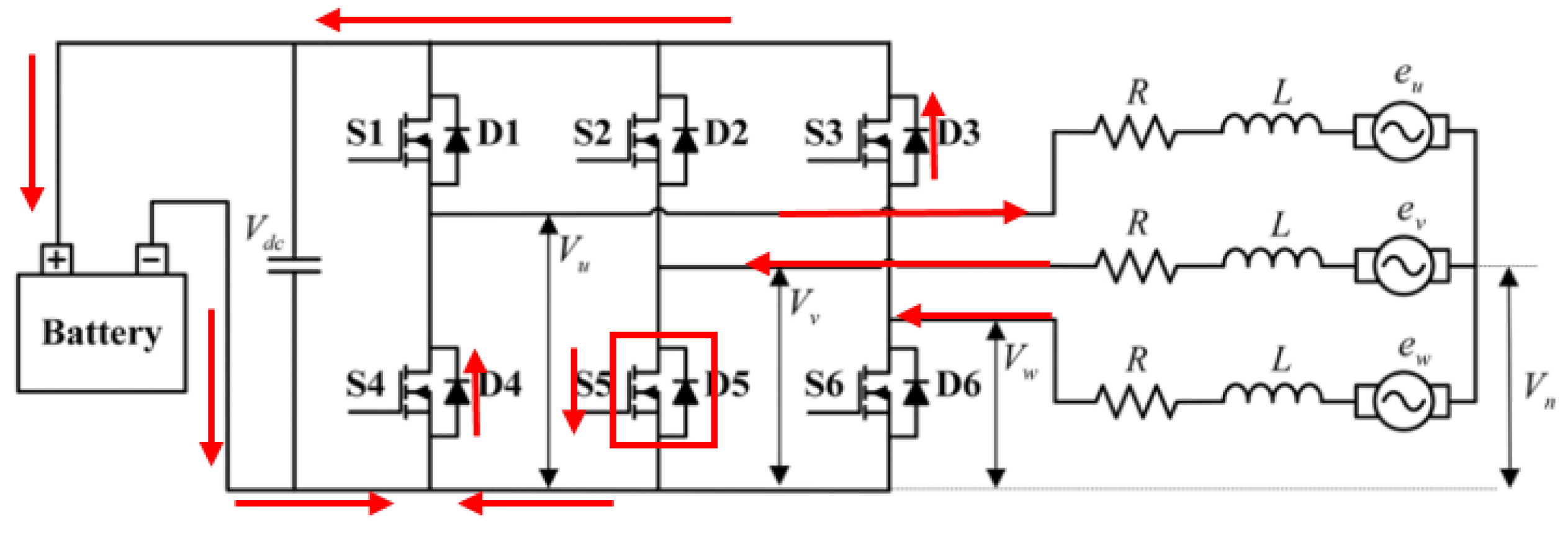
2. Losses in Electrical Machine and Inverter

To effectively analyze and control IPMSMs, mathematical modeling is employed to transform the three-phase stator currents into an equivalent two-axis coordinate system using the Clarke and Park transformation. This simplifies the representation of motor dynamics and facilitates precise control [13,14,15]. The electromagnetic torque in an IPMSM consists of both magnetic and reluctance torque components, contributing to its high efficiency and performance [16]. The governing equations describe the relationship between flux linkages, current components, and torque production, forming the foundation for advanced control strategies. Mathematically, the electromagnetic torque equation for IPMSMs is expressed as
T e = 3 2 . P 2 . φ m i q + L d L q i q . i d
where P is the number of pole pairs, φm represents the permanent magnet flux, and id, iq denote the d-axis and q-axis stator currents, respectively. Ld and Lq denote the d-axis and q-axis inductances, respectively. MTPA, which is a conventional method, aims to achieve the highest torque per current by minimizing the magnitude of the input current for a given torque output, as shown in Figure 1 [17]. This technique is crucial for improving the motor’s efficiency by reducing copper losses, which are directly proportional to the magnitude of the current vector for the given constant-torque curve. However, the MTPA approach considers the copper loss in the motor but not the losses in the inverter.
The inverter is positioned between the DC power source and the electrical machine, converting the DC input into variable-frequency AC for motor control in the motoring mode. In the regenerative mode, it reverses its function to convert the AC generated by the generator back into DC, enabling efficient energy recovery and storage in the battery, as shown in Figure 2. The total powertrain loss is obtained by summing the electrical machine and inverter losses.
Figure 2. Single switching model for three-phase, two-level IGBT converter.
Actuators 14 00326 g002
L t o t a l = ( L C u + L C o ) + ( L T s w + L D s w + L T c o n + L D c o n ) + L o t h e r
where L indicates the loss in the electrical machine and the subscripts Cu and Co describe the copper loss and the core loss in the electrical machine, respectively. The subscripts Tsw, Dsw, Tcon, and Dcon describe the transistor switching loss, diode switching loss, transistor conduction loss, and diode conduction loss in the inverter, respectively. The subscript other represents all unmodeled losses, such as bearing friction, winding skin effect, and similar factors. While a complete loss model including these losses would improve the accuracy of absolute efficiency estimation, they were not considered in this study. As noted, these losses are considered to be either static at a given operating point (e.g., friction), negligible in magnitude, or uncontrollable [18,19,20]. These include copper losses resulting from resistive heating within the electrical machine windings, as well as core losses arising from fluctuations in magnetic flux density [21]. Inverter losses can be categorized into switching losses and conduction losses. Switching losses arise during the transition of semiconductor devices such as MOSFETs or IGBTs between ON and OFF states [22]. These losses are influenced by the charging/discharging of capacitances and the transition time. Conduction losses result from the voltage drop across semiconductor devices when conducting current. Although inverter losses—such as switching and conduction losses—are generally smaller than electrical machine losses, they still contribute to total powertrain inefficiency. Therefore, minimizing inverter loss presents an opportunity to further improve the overall system efficiency. By systematically analyzing and minimizing these losses, overall efficiency and regenerative braking effectiveness in IPMSMs can be improved. For the theoretical modeling, each loss is expressed as
L C u   = R s .   I d 2 + I q 2
L C o   = K e d d y   . f 2 . B 2 + K h y s t . f . B 1.6
L T s w = f · 1 n   j = 1 n E o n ( i a > 0 o n   | | i a < 0 o f f ) + f ·   1 n   j = 1 n E o f f (   i a < 0 o n   | | i a > 0 o f f )
  L D s w = f ·   1 n   j = 1 n E r r   i a < 0 o n   | | i a > 0 o f f  
L T c o n = 1 T 0 T | i a | ( V T + r T | i a | ) d t s a = 1 & & ( i a > 0 ) | | s a = 0 & & i a < 0
L D c o n = 1 T 0 T | i a | ( V D + r D | i a | ) d t s a = 1 & & ( i a < 0 ) | | s a = 0 & & i a > 0
where K h y s t   a n d   K e d d y are the hysteresis loss coefficient and eddy current loss coefficient, respectively. f is the switching frequency and B is the magnetic flux. ia indicates the current. Eon and Eoff are the losses when the transistors are turned on and off, respectively. Err is the diode recovered energy. VD and VT are the voltage across the diode and transistor, respectively. r D and r T are the resistance in the diode and transistor, respectively. Sa indicates the state of the corresponding switch, and 0 and 1 denote turning off and turning on, respectively. These parameters related to switching devices and diodes are typically provided by the manufacturer’s datasheet and are adjusted based on the operation points of the components. The inverter operates in a three-phase configuration, and the total inverter losses are obtained by summing the individual phase losses.
The inverter loss is closely related to the switching strategy, which involves coordinating the timing and duration of switching events to achieve the desired motor performance [23]. Proper coordination is essential for minimizing switching losses, reducing electromagnetic interference, and improving overall system efficiency. In this work, a single switching control strategy is adopted, where only one power switch is activated per phase leg. This significantly reduces switching losses and is particularly suitable for light electric vehicles. Figure 2 illustrates the current flow when switch S5 is conducting, and Table 1 compares the number of active components used in the single switching configuration [24]. Compared to the Space Vector Pulse Width Modulation (SVPWM) method typically used in the motoring mode [25], the single switching method applied in the generator mode results in lower inverter losses due to the use of fewer switching devices. This reduction in active components leads to improved energy efficiency. The single switching method produces more current harmonics and a more concentrated current path. These factors can increase copper loss, particularly under higher load conditions. The improvement of efficiency is expected to be pronounced in light-load or low-speed regions, where switching losses constitute a larger portion of the total system losses. Based on this single-switching inverter model in the regenerative mode, the optimal switching time and duration are determined by the control algorithm, and the applied voltage to the electrical machine winding is modulated.

3. Simulation and Analysis

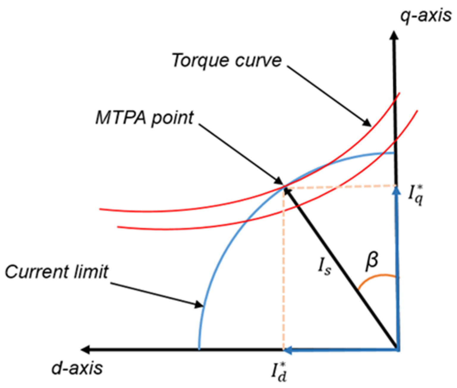
3.1. Simulation of MTPA and TLMM Regenerative Efficiency Under Specific Conditions

In the simulation, a powertrain model was developed with Simulink and the Simscape model in MATLAB r2023b. The model incorporates a three-phase IGBT-diode inverter and an IPMSM, closely replicating the experimental setup. To evaluate the powertrain’s performance, the loss models described in Equations (3)–(8) were integrated into the Simulink environment. These loss models account for both inverter losses and electrical machine losses, ensuring that the combined efficiency of the system could be assessed comprehensively.
It was challenging to determine the minimum-loss conditions directly from the loss equations. Therefore, the search range was narrowed to a region near the MTPA operating points instead of evaluating all possible current combinations. Since the electrical machine’s copper loss (I2R) is one of the most dominant factors in the total system loss, it is a reasonable assumption that the optimal efficiency point for the entire system would not deviate significantly from this point. First, the MTPA current references were theoretically identified. Then, the current values were incrementally varied around these references within 1 A radius, and the efficiency was measured under each condition until the maximum value was found.
The simulation for the low-speed region was conducted at a speed of 1000 rpm and a torque of 200 Nm. Under these conditions, the MTPA current combination was obtained as Id = −65.3 A and Iq = −127.3 A. Table 2 compares the combined efficiency between the MTPA and Total Loss Minimization (TLMM) current combinations obtained through simulation. The maximum combined efficiency was achieved at Id = −65.9 A and Iq = −126.6 A, indicating the minimum total loss in the powertrain. The current combination that maximizes total efficiency shifts toward the upper-left region in the id–iq plane in the regenerative mode.
Similarly to the low-speed case, the simulation for the high-speed region was performed by varying the current values within a 1 A radius around the MTPA current combination. In this case, the speed was set to 4000 rpm and the torque to 100 Nm. Table 3 compares the MTPA and TLMM current combinations and their corresponding efficiencies.
The maximum combined efficiency was achieved at Id = −32.5 A and Iq = −70.6 A, showing a slight improvement over the MTPA result. This optimal current combination also shifted toward the upper-left region in the IdIq plane in the regenerative mode, consistent with the trend observed in the low-speed condition.

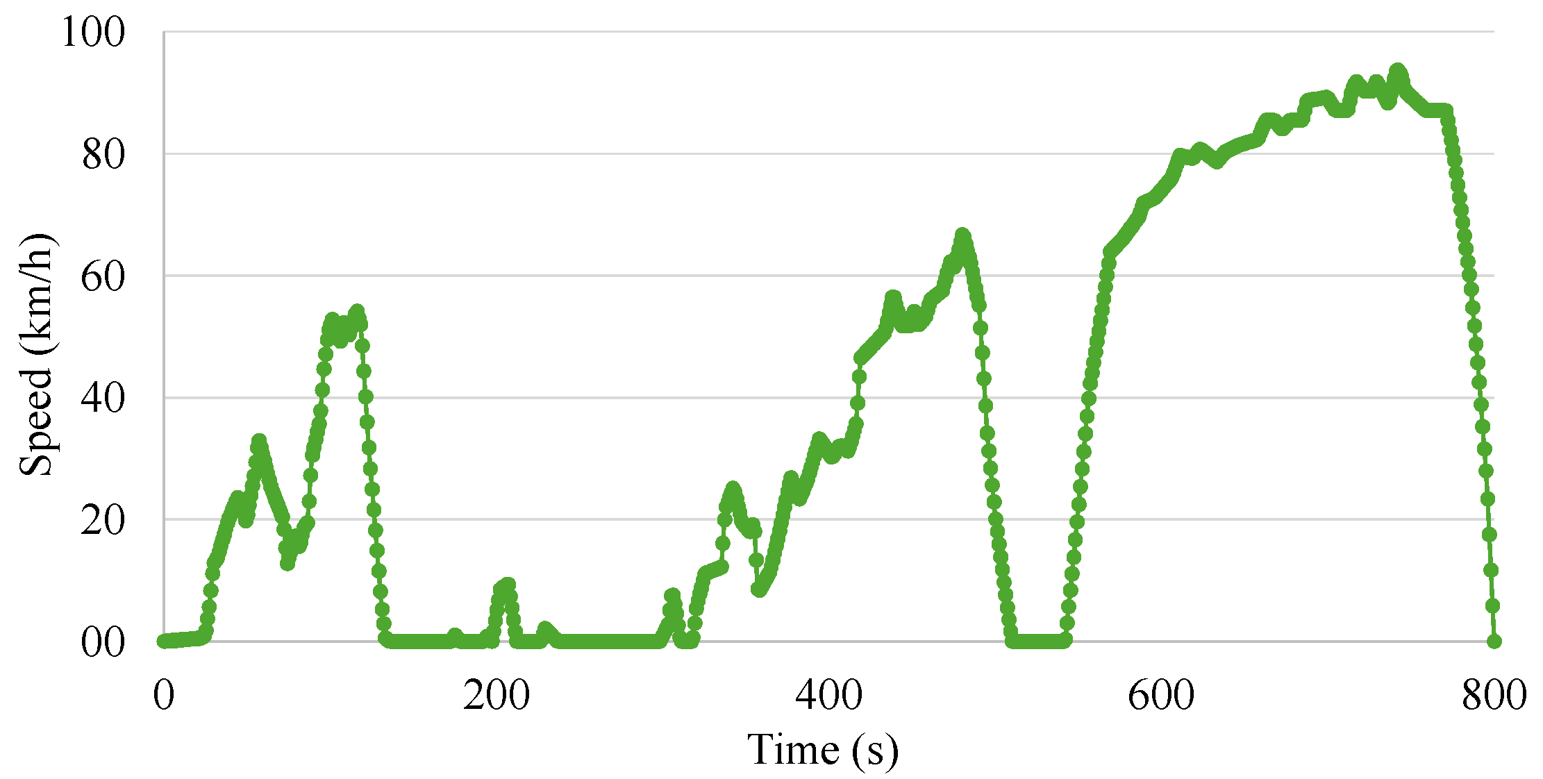
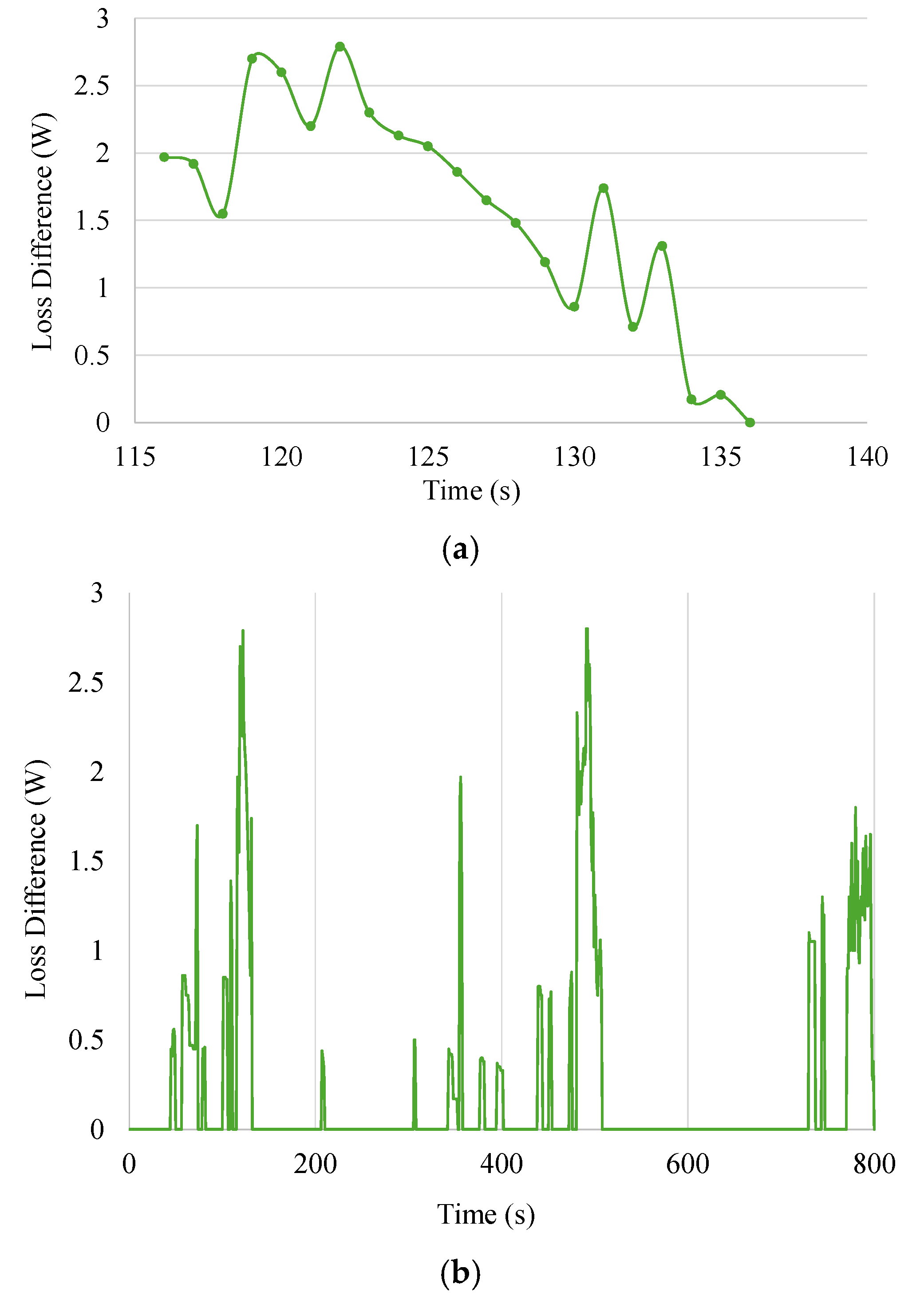
3.2. Comparison of Loss Differences During the UDDS Cycle

For a given operating point, the efficiency difference between MTPA and TLMM is approximately 0.2 to 0.3%, which is relatively small. Therefore, to evaluate the practical benefit of TLMM, the total additional energy recovered by TLMM compared to MTPA was analyzed over the EPA UDDS cycle, as shown in Figure 3.
To cover the full range of speed and torque conditions in the drive cycle, a lookup table of optimal current combinations was constructed based on simulations performed across the range of operating points. This lookup table enabled efficient mapping of current references to minimize total powertrain loss. Figure 4 illustrates the normalized Id and Iq current combinations for both MTPA and TLMM at different torque levels in the regenerative mode. The TLMM operating points shift to the left and upward in the third quadrant. While the difference in current is small at a low torque, it becomes increasingly significant as the torque level rises.
Figure 5a illustrates the loss differences between the two approaches where the deceleration is high in the UDDS cycle and the recover energy is high. Figure 5b shows the total loss differences over the entire time. TLMM was able to capture approximately 0.8–1% more energy during the braking and deceleration phases compared to the traditional MTPA method. Although this improvement might seem marginal at first glance, it is significant in the context of energy efficiency and sustainability. Over the lifespan of an EV, even small improvements in energy recovery can lead to substantial savings in energy consumption and reductions in environmental impact. To provide a clearer picture of these findings, Table 4 outlines the amount of energy recovered by each method during a single UDDS driving cycle. This not only confirms that our approach works but also shows how it can make a real difference in improving overall system performance and using energy more effectively. The UDDS cycle simulation confirmed an increase in energy recovery of approximately 0.9%. While it is acknowledged that this gain might be reduced in a real-world vehicle application due to system-level factors—such as mechanical brake intervention reducing the energy available for recovery, and the battery’s state of charge limiting the ability to store that recovered energy—this incremental improvement is still considered a meaningful achievement.

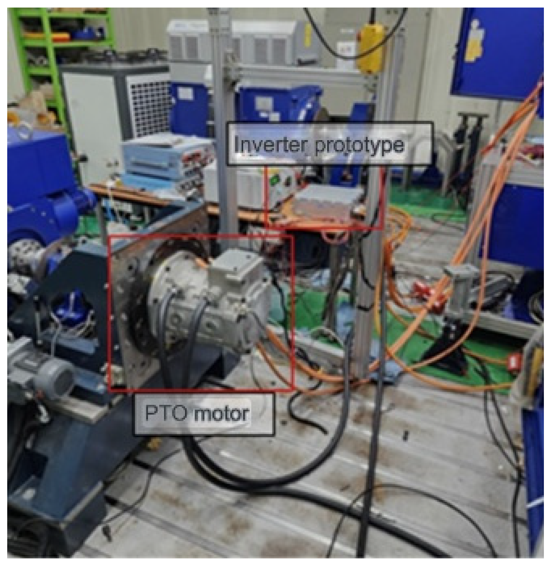
4. Experimental Setup and Results

The proposed TLMM was experimentally validated using a test setup consisting of a PTO (Power Take-Off) electrical machine and an inverter prototype, as shown in Figure 6. The PTO electrical machine served as the prime mover, delivering mechanical input in the form of torque and speed to the IPMSM (Model: PMW160L4P2), which operated in the generator mode. The main specifications of the IPMSM are listed in Table 5. The efficiency measurements were conducted with high-precision instrumentation. An AVL X-ion e-Power analyzer, coupled with an AVL FEM 4™ HV–V-Module for voltage sensing and an AVL FEM 4™ I-Module for current sensing (±24 mA to ±2000 A), was used to measure the input electrical power. The output mechanical power was determined from the shaft torque and speed, which were measured by an AVL Dynamic Torque Transducer and a Tamagawa Smartsyn Brushless Resolver (TS2625N21, Tamagawa Seiki, Nagano, Japan), respectively. A cooling system was implemented to ensure thermal stability during prolonged operation. Additionally, communication lines connected the inverter, sensors, and data acquisition system to enable accurate monitoring and control.
Two operating conditions, 1000 rpm at 200 Nm (low-speed region) and 4000 rpm at 100 Nm (high-speed region), were tested as in the simulation. For each condition, the MTPA current reference combination was identified as the point that maximizes motor efficiency, based on the theoretical MTPA framework. This served as the baseline for comparison. Then, current combinations within a 1 A radius around the MTPA point were tested, following the same procedure as in the simulation. The combined efficiency—reflecting the generator’s operating behavior—was measured for each tested combination.
Table 6 presents the best efficiency for each tested current combination near the MTPA point. In both operating conditions, the optimal current values obtained from the experiment were slightly higher than the simulation results, while the measured efficiencies were slightly lower. Nevertheless, the TLMM consistently demonstrated better efficiency than the MTPA method.

5. Discussion and Experiments

The results demonstrate that although the MTPA current combination provides a high motor efficiency, an alternative current combination yields a higher overall system efficiency, suggesting the potential for reducing total powertrain losses. These findings highlight a shift in the optimal efficiency point when considering the entire system rather than the electrical machine efficiency alone. The identified current combinations from both the simulation and experiments show a similar trend, indicating the validity of the results. Simulation results show that the proposed TLMM achieves approximately 1% lower total losses compared to the MTPA strategy, demonstrating tangible benefits in terms of EV energy efficiency and driving range. A slight difference was observed between the experimental and simulation efficiencies, with simulation values being slightly higher. This discrepancy arises because the simulation did not account for additional minor losses, such as stray load losses, bearing friction, windage, and other thermal losses. A potential limitation of this study is the finite resolution of the current sensors used in the experimental setup, which may have introduced minor inaccuracies in measurement accuracy. Furthermore, real-world factors like noise and vibration, which are not modeled in simulation, contribute to the observed gap between simulated and experimental results. Future work will focus on the effect of the unmodeled losses and perform experimental validation of the system’s dynamic response under the proposed steady-state optimization strategy.

Author Contributions

Conceptualization, J.S. and K.-m.L.; methodology, J.S. and K.-m.L.; software, J.S.; validation, J.S.; formal analysis, J.S.; investigation, J.S.; resources, J.S.; data curation, J.S.; writing—original draft preparation, J.S.; writing—review and editing, K.-m.L.; visualization, J.S.; supervision, K.-m.L.; project administration, K.-m.L.; funding acquisition, K.-m.L. All authors have read and agreed to the published version of the manuscript.

Funding

This work was supported by a National Research Foundation of Korea (NRF) grant funded by the Korean government (Ministry of Science and ICT) (No. NRF-2020R1A2C1007312). This research was also supported by a Korea Institute of Energy Technology Evaluation and Planning (KETEP) grant funded by the Korean government (MOTIE) (20214000000090, Fostering Human Resources Training in Advanced Hydrogen Energy Industry).

Data Availability Statement

Data are contained within the article.

Conflicts of Interest

The authors declare no conflicts of interest.

References

  1. Al-Ghaili, A.M.; Kasim, H.; Aris, H.; Al-Hada, N.M. Can electric vehicles be an alternative for traditional fossil-fuel cars with the help of renewable energy sources towards energy sustainability achievement? Energy Inform. 2022, 5 (Suppl. 4), 60. [Google Scholar] [CrossRef]
  2. Li, L.; Liu, Q. Research on IPMSM drive system control technology for electric vehicle energy consumption. IEEE Access 2019, 7, 186201–186210. [Google Scholar] [CrossRef]
  3. Pinky, K.; Reeba, S.V. Torque improvement in IPMSM for Electric vehicle application. In Proceedings of the 2015 International Conference on Control Communication & Computing India (ICCC), Trivandrum, India, 19–21 November 2015; IEEE: New York, NY, USA, 2015. [Google Scholar] [CrossRef]
  4. Zhang, K.; Li, J.; Ouyang, M.; Gu, J.; Ma, Y. Electric braking performance analysis of PMSM for electric vehicle applications. In Proceedings of the 2011 International Conference on Electronic & Mechanical Engineering and Information Technology, Harbin, China, 12–14 August 2011; IEEE: New York, NY, USA, 2011; Volume 5. [Google Scholar] [CrossRef]
  5. U.S. Department of Energy, Energy Requirements for Combined City/Highway Driving—Electric Vehicles. FuelEconomy.Gov. Available online: https://www.fueleconomy.gov/feg/atv.shtml (accessed on 25 May 2025).
  6. Gupta, U.; Yadav, D.K.; Panchauli, D. Field oriented control of PMSM during regenerative braking. In Proceedings of the 2019 Global Conference for Advancement in Technology (GCAT), Bangalore, India, 18–20 October 2019; IEEE: New York, NY, USA, 2019. [Google Scholar] [CrossRef]
  7. Ozcira, S.; Bekiroglu, N.; Senol, I. Dynamic performance and analysis of direct torque control method based on DSP for PMSM drives. In Proceedings of the 2012 International Conference on Renewable Energy Research and Applications (ICRERA), Nagasaki, Japan, 11–14 November 2012; IEEE: New York, NY, USA, 2012. [Google Scholar]
  8. Kim, D.-Y.; Lee, J.-H.; Ko, A.-Y.; Won, C.-Y.; Kim, Y.-R. Braking torque control method of IPMSM for electric vehicle using 2D look-up table. In Proceedings of the 2013 IEEE International Symposium on Industrial Electronics, Taipei, Taiwan, 28–31 May 2013; IEEE: New York, NY, USA, 2013. [Google Scholar] [CrossRef]
  9. Won, I.-K.; Hwang, J.-H.; Kim, D.-Y.; Jang, Y.-H.; Won, C.-Y. Performance improvement of IPMSM using finite predictive current control for EV. In Proceedings of the 2015 IEEE 2nd International Future Energy Electronics Conference (IFEEC), Taipei, Taiwan, 1–4 November 2015; IEEE: New York, NY, USA, 2015. [Google Scholar] [CrossRef]
  10. Mishra, A.; Mahajan, V.; Agarwal, P.; Srivastava, S. Fuzzy logic based speed and current control of vector controlled PMSM drive. In Proceedings of the 2012 2nd International Conference on Power, Control and Embedded Systems, Allahabad, India, 17–19 December 2012; IEEE: New York, NY, USA, 2012. [Google Scholar] [CrossRef]
  11. Liu, F.; Zhang, D.; Mohammed, S.; Calvi, A. A PMSM fuzzy logic regenerative braking control strategy for electric vehicles. J. Intell. Fuzzy Syst. 2021, 41, 4873–4881. [Google Scholar] [CrossRef]
  12. Yang, Y.; He, Q.; Chen, Y.; Fu, C. Efficiency optimization and control strategy of regenerative braking system with dual motor. Energies 2020, 13, 711. [Google Scholar] [CrossRef]
  13. Akatsu, K.; Narita, K.; Sakashita, Y.; Yamada, T. Characteristics comparison between SPMSM and IPMSM under high flux density condition by both experimental and analysis results. In Proceedings of the 2008 International Conference on Electrical Machines and Systems, Wuhan, China, 17–20 October 2008; IEEE: New York, NY, USA, 2008. [Google Scholar]
  14. Kummerow, A.; Alramlawi, M.; Dirbas, M.; Nicolai, S.; Bretschneider, P. Clark-Park Transformation based Autoencoder for 3-Phase Electrical Signals. In Proceedings of the 2023 IEEE PES Innovative Smart Grid Technologies Europe (ISGT EUROPE), Grenoble, France, 23–26 October 2023; IEEE: New York, NY, USA, 2023. [Google Scholar] [CrossRef]
  15. Uddin, M.; Radwan, T.; Rahman, M. Performance of interior permanent magnet motor drive over wide speed range. IEEE Trans. Energy Convers. 2002, 17, 79–84. [Google Scholar] [CrossRef]
  16. Song, L.; Jiang, D.; Cui, S.; Sheng, S. Reluctance torque analysis and reactance calculation of IPM for HEVs based on FEM. In Proceedings of the 2010 IEEE Vehicle Power and Propulsion Conference, Lille, France, 1–3 September 2010; IEEE: New York, NY, USA, 2010. [Google Scholar] [CrossRef]
  17. Wang, Z.; Yao, X.; Liu, J.; Xu, L.; Tong, H.; Liu, K. Research on IPMSM control based on MTPA. Procedia Comput. Sci. 2022, 208, 635–641. [Google Scholar]
  18. Hargreaves, P.A.; Mecrow, B.C.; Hall, R. Calculation of iron loss in electrical generators using finite-element analysis. IEEE Trans. Ind. Appl. 2012, 48, 1460–1466. [Google Scholar] [CrossRef]
  19. Caruso, M.; Di Tommaso, A.; Miceli, R.; Nevoloso, C.; Spataro, C.; Viola, F. Characterization of the parameters of interior permanent magnet synchronous motors for a loss model algorithm. Measurement 2017, 106, 196–202. [Google Scholar] [CrossRef]
  20. Morimoto, S.; Tong, Y.; Takeda, Y.; Hirasa, T. Loss minimization control of permanent magnet synchronous motor drives. IEEE Trans. Ind. Electron. 1994, 41, 511–517. [Google Scholar] [CrossRef]
  21. Hang, J.; Wu, H.; Ding, S.; Huang, Y.; Hua, W. Improved loss minimization control for IPMSM using equivalent conversion method. IEEE Trans. Power Electron. 2020, 36, 1931–1940. [Google Scholar] [CrossRef]
  22. Pou, J.; Osorno, D.; Zaragoza, J.; Jaen, C.; Ceballos, S. Power losses calculation methodology to evaluate inverter efficiency in electrical vehicles. In Proceedings of the 2011 7th International Conference-Workshop Compatibility and Power Electronics (CPE), Tallinn, Estonia, 1–3 June 2011; IEEE: New York, NY, USA, 2011. [Google Scholar]
  23. Nian, X.; Peng, F.; Zhang, H. Regenerative braking system of electric vehicle driven by brushless DC motor. IEEE Trans. Ind. Electron. 2014, 61, 5798–5808. [Google Scholar] [CrossRef]
  24. Chen, C.-H.; Chi, W.-C.; Cheng, M.-Y. Regenerative braking control for light electric vehicles. In Proceedings of the 2011 IEEE Ninth International Conference on Power Electronics and Drive Systems, Singapore, 5–8 December 2011; IEEE: New York, NY, USA, 2011. [Google Scholar] [CrossRef]
  25. Naidu, A.S.; Samanta, S. Analysis of IPMSM motor by using SPWM and SVPWM based vector controller with MTPA control strategy. In Proceedings of the 2022 IEEE 10th Power India International Conference (PIICON), New Delhi, India, 25–27 November 2022; IEEE: New York, NY, USA, 2022. [Google Scholar]
Figure 1. MTPA model in d-q reference frame.
Actuators 14 00326 g001
Figure 3. UDDS data chart used for simulation.
Actuators 14 00326 g003
Figure 4. MTPA and TLMM conditions for different torque values.
Actuators 14 00326 g004
Figure 5. Simulation results for the additional energy recovered by TLMM: (a) during the time interval from 116 s to 131 s, (b) over the entire UDDS cycle.
Actuators 14 00326 g005
Figure 6. MTPA and TLMM trajectory for different torque values.
Actuators 14 00326 g006
Table 1. Number of IGBTs and diodes use in motor mode and generator mode.
Number of IGBTsNumber of Diodes
Motor mode (SVPWM)33
Generator mode (Single Switch)12
Table 2. Simulation results for MTPA and Total Loss Minimization current combinations (low-speed region).
Id (A)Iq (A)Total Efficiency
MTPA−65.29−127.310.938
TLMM−65.89−126.640.941
Table 3. Simulation results for MTPA and Total Loss Minimization current combinations (high-speed region).
Id (A)Iq (A)Total Efficiency
MTPA−31.80−71.320.966
TLMM−32.48−70.620.968
Table 4. Energy recovered through MTPA and Total Loss Minimization Method in UDDS cycle.
MTPATLMMDifference
Energy Recovered (J)21,74621,944198
Table 5. PMSM specifications used for experiment.
Specification
Torque440 Nm
Nominal Speed3473 rpm
Maximum Speed16,000 rpm
Weight435 kg
J0.061 kg·m2
Nominal Load160 kW
DC Voltage700 V
Table 6. Experimental results for MTPA and Total Loss Minimization current combinations.
Id (A)Iq (A)Total Efficiency
Low SpeedMTPA−65.91−128.60.920
TLMM−66.52−127.920.923
High SpeedMTPA−32.11−72.040.952
TLMM−32.82−71.330.954
Disclaimer/Publisher’s Note: The statements, opinions and data contained in all publications are solely those of the individual author(s) and contributor(s) and not of MDPI and/or the editor(s). MDPI and/or the editor(s) disclaim responsibility for any injury to people or property resulting from any ideas, methods, instructions or products referred to in the content.

