Article

Distributed Sensing Enabled Embodied Intelligence for Soft Finger Manipulation

by
Chukwuemeka Ochieze
1,
Zhen Liu
2 and
Ye Sun
1,3,*
1
Department of Mechanical and Aerospace Engineering, University of Virginia, Charlottesville, VA 22903, USA
2
Department of Civil and Environmental Engineering, University of Virginia, Charlottesville, VA 22903, USA
3
Department of Electrical and Computer Engineering, University of Virginia, Charlottesville, VA 22903, USA
*
Author to whom correspondence should be addressed.
Actuators 2025, 14(7), 348; https://doi.org/10.3390/act14070348 (registering DOI)
Submission received: 5 June 2025 / Revised: 6 July 2025 / Accepted: 11 July 2025 / Published: 15 July 2025
(This article belongs to the Special Issue Soft Robotics: Actuation, Control, and Application)

Abstract

Soft continuum robots are constructed from soft and compliant materials and can provide high flexibility and adaptability to various applications. They have theoretically infinite degrees of freedom (DOFs) and can generate highly nonlinear behaviors, which leads to challenges in accurately modeling and controlling their deformation, compliance, and behaviors. Inspired by animals, embodied intelligence utilizes physical bodies as an intelligent resource for information processing and task completion and offloads the computational cost of central control, which provides a unique approach to understanding and modeling soft robotics. In this study, we propose a theoretical framework to explain and guide distributed sensing enabled embodied intelligence for soft finger manipulation from a physics-based perspective. Specifically, we aim to provide a theoretical foundation to guide future sensor design and placement by addressing two key questions: (1) whether and why the state of a specific material point such as the tip trajectory of a soft finger can be predicted using distributed sensing, and, (2) how many sensors are sufficient for accurate prediction. These questions are critical for the design of soft and compliant robotic systems with embedded sensing for embodied intelligence. In addition to theoretical analysis, the study presents a feasible approach for real-time trajectory prediction through optimized sensor placement, with results validated through both simulation and experiment. The results showed that the tip trajectory of a soft finger can be predicted with a finite number of sensors with proper placement. While the proposed method is demonstrated in the context of soft finger manipulation, the framework is theoretically generalizable to other compliant soft robotic systems.

1. Introduction

Soft robots are constructed from highly compliant materials and structures that constitute their unique intrinsic adaptability to diverse environments, enhanced safety, service dexterity, and flexibility for various applications due to their diverse deformability via soft bodies and designs. Unlike traditional rigid robots, soft robots can undergo complex and nonlinear deformations, making it challenging to model their behavior accurately.
Soft and compliant robots, particularly those utilizing pneumatic actuation, have become prominent in robotic systems that require safe, adaptive, and versatile interactions with humans and unstructured environments. Their compliant bodies can undergo large continuous deformations, making them ideal for applications in rehabilitation, prosthetics, and bioinspired manipulation [1]. Among them, soft fingers are pneumatic actuators that provide dexterous and adaptive grasping capabilities by conforming to object geometries through pressure-induced deformation, enabling robust manipulation even with limited sensory feedback. A number of studies have contributed significantly to the modeling and control of soft fingers. Previous studies developed theoretical models rooted in continuum mechanics and beam theory to describe actuator deformation under pressure inputs [2]. For instance, models of soft fingers often capture the bending curvature and pressure-length relationship through geometric and material parameters [3,4]. Sensing strategies have also been proposed to estimate soft body deformation [5], which enables real-time feedback and motion prediction. In addition, experimental studies have demonstrated remarkable performance in controlling soft fingers using pressure feedback, deformation-based sensing, or curvature estimation for closed-loop control and learning [6,7,8]. In order to offload the computational cost of central control, the compliance of soft robots, due to their theoretically infinite degrees of freedom (DoFs), has been considered as a unique resource for tasking.
In compliant biological systems, embodied intelligence is the intelligence of the physical body that can leverage its own physical morphology (e.g., shape, material, structure, etc.) and external interactions with surrounding environments to achieve desired motions with low or no central control [9]. This means the compliant and deformable nature of soft robots can adapt themselves as computational resources by leveraging their morphology and physics influenced by geometry design, material properties, and interaction with its environment, to offload some of its computational burden from a controller to its physical structure. However, embodied intelligence is more than the common design guidelines, which provide the insights that the physical body and its interaction with surrounding environments can provide more information for intelligence to offload or even remove the necessity of central control [10,11]. This concept has been successfully implemented in various studies [12,13], often employing reservoir computing, where the soft body itself functions as a nonlinear computational medium. This method is commonly known as morphological computation [14,15]. In real applications, distributed sensors are often used to provide sufficient real-time information that represents the nonlinear dynamics of soft robots in reservoir computing [16]. Such sensing enables the generation of adaptive motion patterns without requiring complex control algorithms [17].
The goal of this study is to provide a detailed theoretical foundation from first principles and guide embodied intelligence for pneumatic soft finger manipulation from a physics perspective. In particular, we aim to theoretically explain two key questions in this article: (1) Why can the state of a specific material point, such as the tip trajectory of a soft finger, be predicted from the states of other material points within the same structure? (2) What is the minimum number of material points (i.e., sensors) required to reliably predict this state? The answers lay the groundwork for distributed sensing enabled embodied intelligence and can be further expanded to the design and placement of distributed sensing for better predicting the behavior of the entire soft robot, leading to an approach to forward mapping.

2. Theoretical Analysis

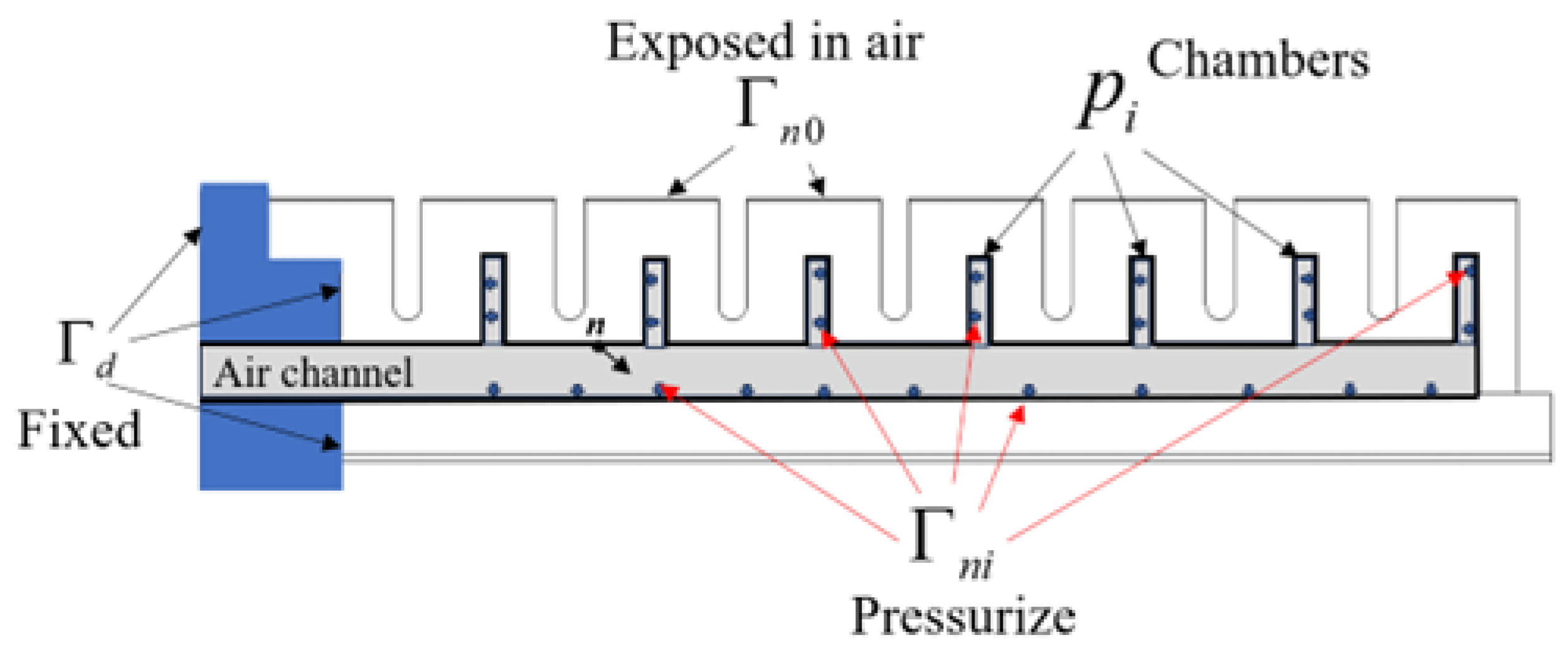
2.1. Physics of Soft Finger Manipulation

To establish a generic method for soft robot modeling and prove it, we start with the fundamental physics of soft bodies. The intrinsic dynamics of a soft robot can be represented by its governing equation in three-dimensional space (i.e., Navier-Cauchy equation) with boundary conditions (BCs), and initial conditions (ICs), considering high deformation scenarios. For pneumatic soft robots, air pressure is applied through multiple inside chambers for actuation as shown in Figure 1. Such actuation will impact the ICs and BCs, and the governing equation for soft bodies remain unchanged once the robot design is completed because the domain physics is only applied to the soft body. The governing equation of soft matter deformation using Navier-Cauchy’s equation is expressed by Equation (1), the IC is expressed by Equation (2), and Equations (3)–(5) are BCs for this case.
ρ 2 u t 2 = ( λ + μ ) ( · u ) + μ 2 u + g p
u = u 0
u = 0 Γ d
n · σ = p i Γ n i , i 0
n · σ = n · λ D · u + μ ( u ) T + μ u = 0 Γ n 0
where ρ is the density of the soft material, u is the displacement vector, 2 is the Laplacian operator that ensures uniformity of the displacement vector, λ and μ are Lame’s constants, g p is the gravitational force per unit volume, n is the unit outward vector on the boundary, σ is the Cauchy stress tensor, D is the identity matrix/tensor, p i is the pressure applied to the ith chamber, which corresponds to the ith Neumann boundary segment Γ n i . These equations govern the linear behavior of elastic materials and are used to analyze the deformation, stress distribution and behavior of our soft robot under applied loads.
Soft materials have long and flexible molecular structures, which can stretch several times the original length. At small strain, such materials can be considered linearly elastic. However, in large deformation, the large elastic deformation theory should be considered. A common theory that assumes a hyper-elastic behavior of silicone can be explained in terms of a strain energy function based on the strain invariants I 1 , I 2 and I 3 .
W = f I 1 , I 2 , I 3
where I 1 , I 2 and I 3 are the three invariants of the Cauchy-Green deformation tensor. This nonlinear continuum mechanics description shows how soft models behave when subjected to significant deformation and are frequently employed for soft robots. A considerable amount of literature has been devoted to modeling material nonlinearity, especially via the modeling and design of hyper-elastic models. In such efforts, the selection of a proper strain energy function, W, and the accurate determination of material constants are the keys. One example of such an equation is the Yeoh model [18]:
W = a 1 I 1 3 + a 2 I 1 3 2 + a 3 I 1 3 3
thus, a 1 , a 2 , a 3 , are the material characteristics that control how much the various strain invariants ( I 1 , I 2 , I 3 ) contribute to the total energy density. Several other hyperelastic models, such as Mooney-Rivlin [19,20], and Ogden models [21], also exist in addition to the Yeoh model, which all depict the hyper-elastic material’s stress-strain relationship. In essence, the interplay between strain energy functions and Navier-Cauchy’s equations provides a comprehensive framework for analyzing material behavior. The strain energy function illuminates the material’s intrinsic response to deformation, while Navier-Cauchy’s equations offer a means to understand the static equilibrium under external forces. Thus, to capture the physical information of soft robot modeling and dynamics from first principles, deflection, trajectory, and configuration are key and should be captured over time.

2.2. Minimal Sensor Placement for Physical Information

Let us consider a general condition, for which the governing physics can be viewed as the superposition of three components: an equilibrium component, a dynamic component, and an external excitation component. The former components reside in the governing equation, while the third component comes into play through boundary conditions. From a mathematical perspective, the governing equation consists of a time-dependent component and a time-independent component as follows:
f u t , 2 u t 2 , , u x , 2 u x 2 , 2 u x y , = 0
The above equation can be discretized using the finite differences to approach the above continuous problem with a numerical model. Such discretization is associated with stencils (or nodes) at selected locations and time points obtained with selected time steps. We can use subscripts i , j , k for the stencil number along the three dimensions in a 3D problem, and subscript r to mark the time step. If the external excitation is time-independent over the period of consideration, then the value of the state variable h at a location ( i , j , k ) in the next time step r can be formulated as
h i , j , k r + 1 = C 0 + t [ 1 , r ] i [ 1 , I ] j [ 1 , J ] k [ 1 , K ] C i , j , k t h i , j , k t
The above equation implies one significant fact: the state variable at any location in the next time step can be calculated as the weighted average of state variable values at other locations (e.g., i [ 1 , I ] in which I is the last point number along the first axis) in the current and/or earlier steps. The coefficients C i , j , k r are determined by the governing equation, boundary condition, and the adopted finite difference scheme. The choice of the finite difference scheme is the key step to the connection of the above equation to the key question. An infinite number of finite schemes are available for discretizing the above governing equation. Among them, there is one finite difference scheme containing only the state variables that can be measured by sensors at given locations. That is, if we can measure the value of a variable such as displacement at given sensing locations, in theory, we can calculate the value of the same variable at any given location as a weighted sum of the measurements, in which the underlying physics and the selected sensing locations and finite difference scheme determine the weights. The above statement can be further extended. This is because many quantities such as displacement, velocity, acceleration, and strain are related through physics, which can be employed to reformulate the above algebraic equation (after discretization). In that way, the value of one variable at any given point can be calculated as the weighted sum of the values of some other state variables measured at selected locations. To exemplify the above theory, let us consider a cantilever, which deforms in a way similar to a soft robotic arm. Consider 2D deformation, which is both common for a soft robotic arm and convenient for outlining the deduction. Among the 2D deformation, the deflection, which is the displacement from the original position in the beam axis, is the predominant. For a beam, this deflection can be described using the Euler-Bernoulli equation:
ρ A 2 w t 2 = 2 x 2 E I 2 w x 2 + q ( x )
where ρ is the mass per unit length, A is the cross-sectional area, w is the deflection, x is the coordinate along the axial direction, E I is the flexural rigidity, and q is the distributed load along the transverse direction (direction of w). During deflection, displacement w represents the transverse component of the overall deformation vector u, discretized along the axis perpendicular to the length of the beam.
For a single soft robotic finger, different shapes can be obtained as we apply different levels of working pressure. This is analogous to the deformation of a beam by applying different q ( x ) . Because we consider the equilibrium shape after applying each pressure, thus the transient response is excluded. Under this condition, Equation (10) is simplified into Equation (11), if the flexural rigidity does not change with x.
E I 4 w x 4 = q ( x )
Let us first see how the deflection of the tip point can be predicted with the deflections at other points. We can discretize the geometry of the beam by dividing it into five equal portions. In that way, the left point, i.e., 1, is fixed, Points 2–5 have sensors that can measure the deflections, and Point 6 is the tip point. The above equation can be discretized using a first-order backward finite difference scheme as follows:
1 l 5 4 w 2 4 w 3 + 6 w 4 4 w 5 + w 6 = 1 E I q
where l is the length of the beam. Therefore, if the deflections of Points 2–5, i.e., w 2 , w 3 , w 4 , w 5 , can be measured, then we can calculate or predict the deflection of the tip point as
w 6 = q l 4 625 E I ( w 2 4 w 3 + 6 w 4 4 w 5 )   = q l 4 625 E I 1 4 6 4 w 2 w 3 w 4 w 5
However, the measurement of some variables like deflection is not that common or convenient. Instead, it is more common to measure relevant quantities such as the bending curvature, which is the second derivative of the deflection ( c = 2 w / x 2 .
1 l 5 2 2 1 0 0 1 2 1 0 0 1 2 1 0 0 1 2 w 2 w 3 w 4 w 5 = c 2 c 3 c 4 c 5 w 6
The above equation adopts a second-order central difference scheme for all the four points. Besides, the boundary condition on the left end, i.e., w 0 = 0 , was also incorporated.
We can reformulate the above equation to calculate the deflections from the measured curvatures.
w 2 w 3 w 4 w 5 = l 2 25 0.8 0.6 0.4 0.2 0.6 1.2 0.8 0.4 0.4 0.8 1.2 0.6 0.2 0.4 0.6 0.8 c 2 c 3 c 4 c 5 w 6
Substituting Equations (13) into (15) for calculating w 6 , we can obtain the following equation:
w 6 = 1 1 l 2 25 q l 4 625 E l l 2 25 C 3 + 2 l 2 25 C 4 l 2 25 C 5
The above equation explains that the deflection at the end point can be calculated as the weighted sum of the bend sensor measurements at Points 3–5. Thus, it is theoretically valid that the status of a particular material point of a soft finger, i.e., the tip trajectory as a practical application case can be predicted with the status of certain material points at other locations (i.e., sensors) in the same soft finger. For this soft finger case, it is theoretically not necessary to use more than four sensors to predict the tip trajectory. For a more complex soft robot, the minimal sensors will vary according to the shape of soft body.

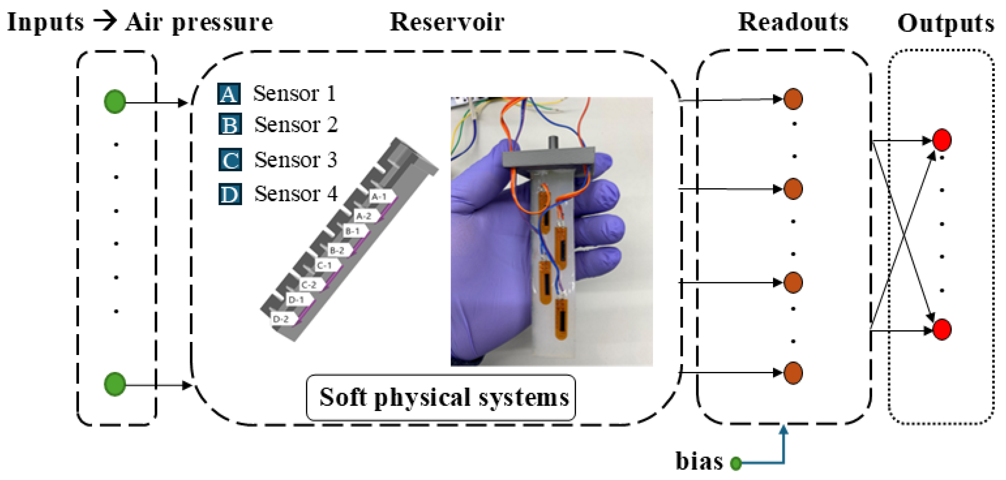
2.3. Physical Reservoir Computing

With the real-time sensing data that represent the nonlinearity of the soft finger, the tip trajectory prediction requires very low computation cost and only needs linear operation of these data. This aligns with the idea of embodied intelligence through reservoir computing. Reservoir computing architecture embodies a reservoir for mapping nonlinear inputs (temporal or sequential data processing) into a high dimensional space such that the readout can be analyzed by a simple learning algorithm (for example linear or polynomial regression) to provide a desired output [16,22]. In this context, the soft robot’s deformable body can be seen as the reservoir, where its material properties and the way it responds to inputs can be harnessed for computation. With the first principles physics of nonlinearity of soft bodies explained in Section 2.1, such soft bodies and their mechanical properties can be exploited to simplify control and enable adaptive behaviors. The computation is only a linear combination of the physical information of the soft body represented by real-time sensing signals, as shown in Figure 2.
From Equations (12)–(16), the variables w 2 w 5 denote the state variables of the physical reservoir, while w 6 represents the desired tip trajectory y ( t ) . Potentially, this implies that the information processed by the soft physical body is encapsulated within w 2 ( t ) w 5 ( t ) , facilitating the prediction of y ( t ) .

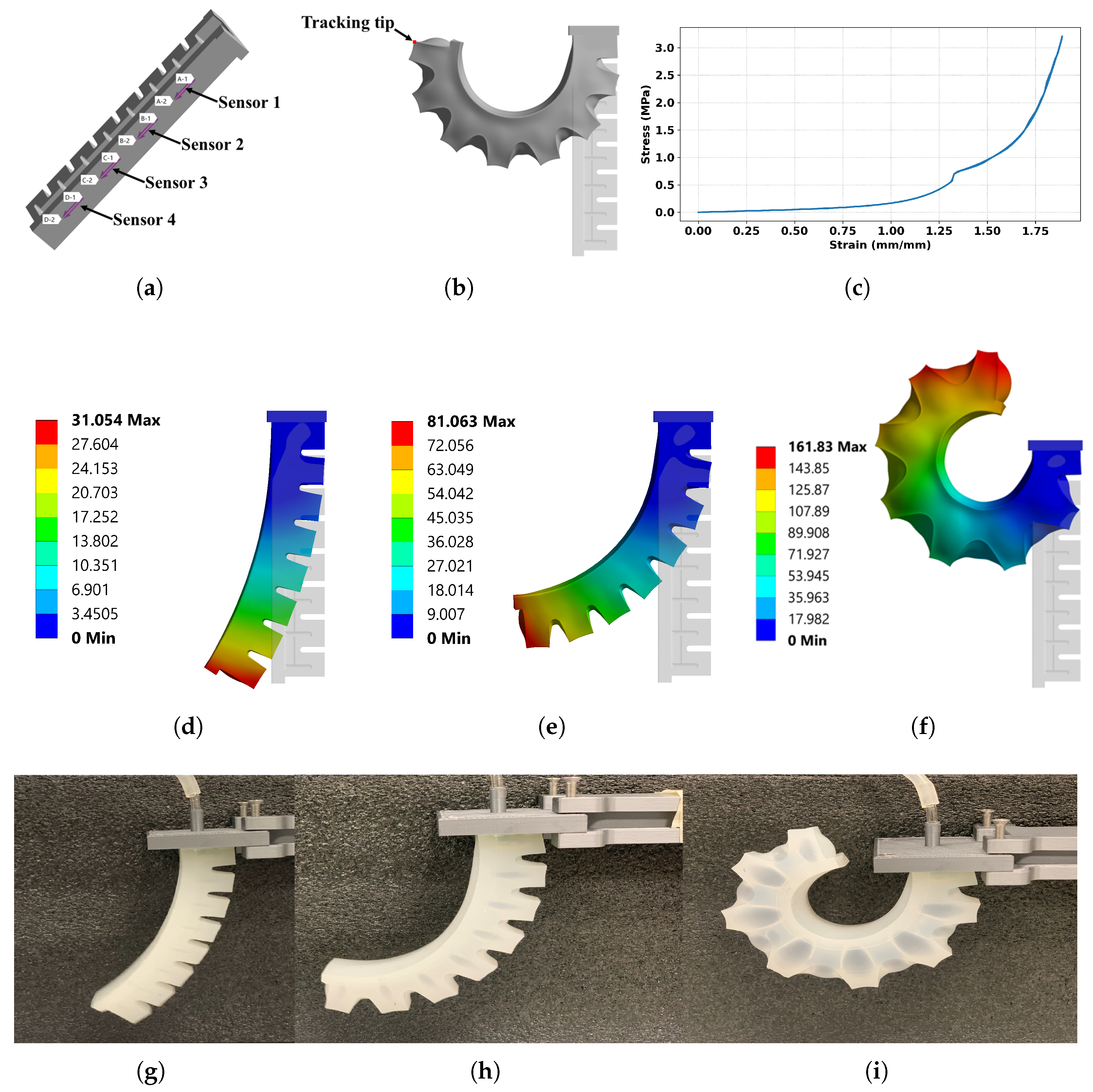
3. Numerical Simulation

First of all, a simulation with finite-element methods of the soft finger was developed for validation because it fully aligns with the theoretical model of the soft finger. The results were compared with experimental data analysis in Section 4 to investigate one major issue: The proposed theoretical analysis is in an ideal condition with the assumption that the sensor data can directly represent the status of material points; however, it might not be true with physical sensor placements because the sensor’s shape and material may affect the soft robot model, and also the sensor data may not fully represent the status of the material points. Thus, we aim to investigate how the physical condition of sensor placement affects the result. The simulation was conducted using ANSYS 2022 R2. In the simulation, we detailed the transient response that the actuator can obtain when pressurized and depressurized. To couple the nonlinearity of soft materials, we implemented Yeoh’s third order model [18], which is an isotropic hyperelasticity model that accounts for the mechanical properties of soft materials in both linear and nonlinear fashion by using a polynomial form to describe the strain-energy density function. The Yeoh model parameters used for the Eccoflex 00-50 were C 10 = 1.58 × 10 2 MPa , C 20 = 4.8 × 10 4 MPa , and C 30 = 1.13 × 10 4 MPa [23], and the density is 1070 kgm 3 .
When setting up the model, we imported the 3D geometry into ANSYS standalone transient structural analysis and ensured that the model was accurately scaled and oriented to represent the experimental setup. Meshes were generated to be sufficiently fine to capture important details, especially near the constrained end and any areas of interest. The boundary conditions were aligned with Section 2. Similar setups were applied for pressure loads of 4 kPa, 10 kPa, and 19 kPa by selecting the air channels of our model for a uniformly applied pressure with the time-dependent behavior of the load varying over time. Figure 3c shows the stress-strain curve of the loading and unloading of the soft robotic finger at 19 kPa, which gives a similar profile in the experimental investigation in [24] for hyper-elastic materials, we observed a similar profile for 4 kPa and 10 kPa. Figure 3d–f show the simulation results of the soft finger’s total deformation pressurized at 4 kPa, 10 kPa, and 19 kPa respectively. The fixed end shows no sign of deflection which is the blue color coding on the color map. With the soft finger pressurized, it gradually deformed throughout the inner walls and chambers causing the finger to curl to a particular shape. The simulation results were well aligned with the experimental results as shown in Figure 3g–i.

4. Experiments

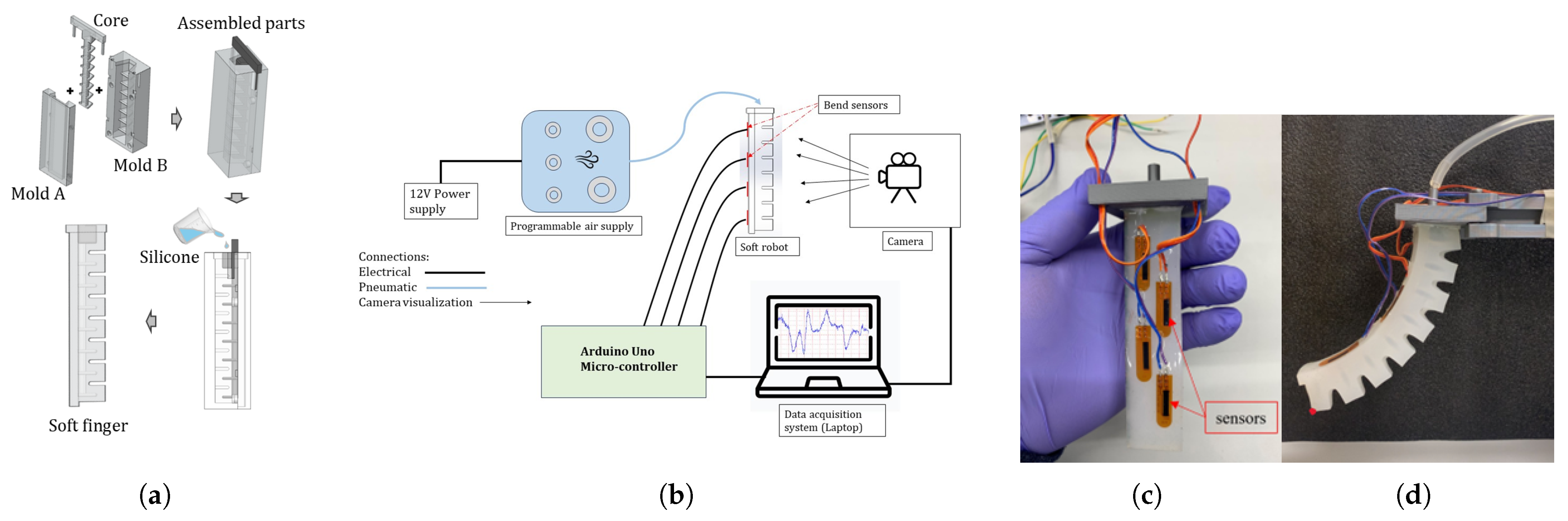
4.1. Design and Fabrication

The soft finger design, Figure 4 with geometrical parameters shown in Table 1 was fabricated using molds and Ecoflex 00-50 (Smooth-On, Inc., Macungie, PA, USA). The design of the molds (2 pieces to create PneuNet) was accomplished by SolidWorks 2022 and 3D printing. To prevent any leakage, the mold was meticulously sealed, ensuring a watertight enclosure for the silicone mixture. The Ecoflex 00-50 comprises two components, part A and part B. A mixing ratio of 1-to-1 for parts A and B was accurately weighed before mixing to achieve a homogeneous blend. To eliminate any trapped air bubbles within the silicone mixture, the homogenized mixture was subjected to a degassing process through a vacuum chamber set at −25 mmHg for a duration of 3 to 5 min. This step was performed before and after pouring the mixture into the mold to ensure optimal results Figure 5a. The curing time for the soft-ridged robot fabrication ranged from 4 to 6 h, allowing sufficient time for the silicone to solidify and acquire the desired mechanical properties. To create the internal air channel, a pre-shaped core (3D-printed or silicone rod) was inserted into the mold cavity prior to casting. Ease Release 200 (Smooth-On Inc.) was applied to the core’s surface before pouring the silicone. After curing, the core was gently extracted by manually wiggling it from side to side, ensuring minimal disruption to the cured structure. This process resulted in a clean internal pneumatic channel as shown in Figure 5a. Four bend sensors (Flexpoint Sensor Systems, Inc., West Jordan, UT, USA) that represent the location w 2 w 5 were placed during the curing process. The final soft finger with sensors is shown in Figure 5c.

4.2. Experimental Setup and Data Collection

The experimental setup was to collect real-time sensor data Figure 5b and capture the tip trajectory of the soft finger Figure 5d to validate the theoretical analysis. The soft finger was pressurized with input air pressure of 4 kPa, 10 kPa, and 19 kPa using Programmable Air controller (tinkrmind, open-source pneumatic platform), which features an onboard mini air pump, pressure sensor, and microcontroller interface for precise pressure modulation. During pressurization and depressurization of the soft finger, changes in strain and stress occurred along the morphology of the soft physical system, which was captured through the four flexible bend sensors. We define these real-time sensor signals as w 1 ( t ) w 5 ( t ) . The tip trajectory was captured using a camera. The recording was analyzed using DeepLabCut [25] for training and post-processing to track and visualize the motion of the tip point, which aligns with our proposed theoretical analysis, w 6 ( t ) .
To obtain precise outcomes, we initiated the process by verifying that the recorded video frames corresponded to the time intervals during the pressurization and de-pressurization of the soft finger. This technique ensures that the timing of soft robot deformation is synchronized with the reading from the bend sensors and the specific tracked spot on the finger.

5. Methods and Results

5.1. Physical Reservoir Computing Implementation

Figure 2 shows the architecture of the physical reservoir computing with the soft finger as the reservoir with real-time data from simulation and experiment. In this setup, the input signal M ( t ) R n that can be temporal or sequential is mapped to the highly nonlinear soft finger with high dimensional states W ( t ) R n and can be read as w i ( t ) to generate the desired output response y ( t ) . In such a way, we are able to show that the sensory time series can be used to predict the tip trajectory of the soft finger. With the soft body taking the nonlinear functions and mapping the input air pressure to a higher dimensional space, the tip trajectory y ( t ) becomes as low computational cost as a linear combination of sensor data.
y ( t ) = i = 0 4 v i w i ( t )
where w 0 ( t ) is a bias, w i ( t ) , i = 1 , , 4 are the bend sensing signals in real-time, and v i is the corresponding linear readout weight. We trained the prediction of y ( t ) using measured sensing data from both the simulation and experiment to acquire the optimal linear readout weights v i , which aligns with our proposed theoretical analysis as detailed in Equations (12)–(16). The linear weights v i were obtained using simple linear regression, following the framework in [13], to minimize the regularized squared error between predicted and actual tip trajectories. The entire time series from each test case (simulation and experiment) was used for training. Our prediction accuracy was quantified using the coefficient of determination and root mean square error (RMSE).

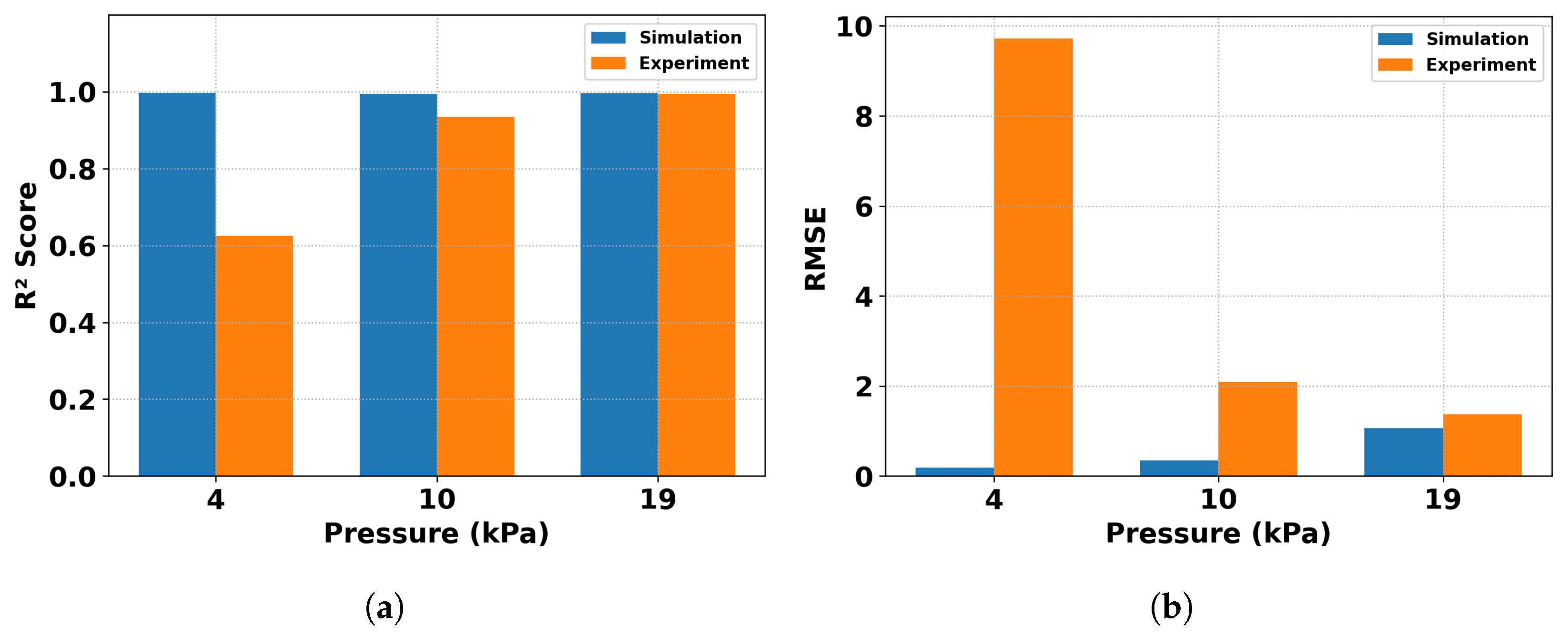
5.2. Prediction Results

For both simulation and experimental data, reservoir computing was applied to investigate whether the proposed theoretical analysis could answer the major two questions for distributed sensing enabled embodied intelligence: (1) Why/whether the status of a particular material point of a soft finger, i.e., the tip trajectory as a practical application case, can be predicted with distributed sensing; and (2) how many sensors are sufficient to predict tip trajectory. The theory detailed in Section 2 explains that the statuses/motions of certain material points, i.e., the goal motion of a soft body, can be predicted by other limited material points. Due to the unique shape of the soft finger, only four sensors are sufficient to predict tip trajectory in real-time.
In the simulation described in Section 2, the status of material points can be extracted from ANSYS. To validate the proposed theoretical analysis, we extracted the corresponding deflection at locations w 2 w 6 from ANSYS. Under different input air pressures, the transient model could provide a transient response of w 2 ( t ) w 6 ( t ) . These material points represent the deflections that can be measured by bend sensors and the tip trajectory, respectively. In the real experiment as described in Section 4, the same status of material points could be measured through bend sensors and video recording with computer vision analysis, respectively.
The resultant graphical representations were analyzed and assessed individually for each applied pressure level. Figure 6a,b compare the measured tip trajectory over time through camera recording in the experiment versus the predicted tip trajectory by real-time bend sensor data through Equation (17) with the input pressure of 10 kPa and 19 kPa. Figure 6c,d compared the measured tip trajectory in the simulation over time at w 6 ( t ) versus the predicted tip trajectory with the extracted material points w 2 ( t ) w 5 ( t ) in the simulation with input pressures of 10 kPa and 19 kPa as well. All predictions were well aligned with the measured tip trajectory. With increased air pressure of 10 kPa and 19 kPa, Figure 6c,d show an improved prediction and information processing between the projected and observed tip trajectories. Although the theoretical formulation assumes quasi-static equilibrium at each pressure step, the experimental and simulation results are analyzed in the time domain. Therefore, the tip displacement is denoted as w 6 ( t ) to reflect the time-dependent measurements aligned with sensor signals and real-time prediction using reservoir computing. With small increase in input pressure, a definite trend toward better prediction accuracy was seen. This phenomenon matches the anticipated increase in morphological computation because of increased pressure levels. At lower input pressures, such as 4 kPa, the soft robot exhibited limited information processing capacity due to increased sensor noise and minimal displacement. As a result, the linear regression output lacked meaningful interpretation. However, the underlying behavior was effectively captured through quantitative metrics such as RMSE and R2 score in Figure 7. However, as the soft robot underwent deformation, its capacity for information processing expanded appreciably. This augmentation was attributed to the distinctive material and geometric nonlinear hyper-elastic characteristics inherent in the soft robot’s behavior.
To evaluate the accuracy of the proposed sensing and regression framework, we examined tip trajectory prediction performance using both simulation and experimental datasets for varying input pressures. While the simulated data achieved a coefficient of determination at R2 > 0.99 across all conditions, the experimental data showed slightly lower determination, particularly at low pressures of 4 kPa, due to minimal displacement and increased sensor noise. To quantify these differences, we computed the coefficient of determination R 2 , and RMSE Figure 7a,b for each condition.
Notably, comparing the prediction results from simulation and experiment, simulation data yielded more accurate prediction outcomes. Such data are in ideal condition and exactly aligned with the proposed theoretical analysis with the usage of material points. With physical sensors embedded, it is understandable that the sensors’ shape and material affect the soft robot’s behaviors and the measured deflection may not be as perfect as simulation. It is worth noting that when examining the prediction responses at 19 kPa, a distinct pattern emerges compared with the simulation data, which exhibits a pronounced curvature in contrast to the experimental results. The bend sensors used (Flexpoint Sensor Systems, Inc.) are constructed with a polyester substrate and have an approximate stiffness of 10–20 Nmm depending on curvature and length. Their base layer is semi-rigid and introduces slight resistance to extension, which acts as an inextensible layer, introducing distinct characteristics to the predictive behavior. Based upon the concept of morphological computation, this study has demonstrated the instrumental role played by physical reservoir computing within soft physical systems. Specifically, these computational capabilities have been harnessed and effectively captured through the implementation of distributed sensing mechanisms. However, the prediction results still show high accuracy, which means the distributed sensor placement can still follow the theoretically suggested locations.

5.3. Discussion

The results demonstrate that distributed sensing and linear regression are sufficient for predicting tip trajectories under pneumatic actuation. While simulation-based predictions exhibited near-perfect determination R 2 > 0.99, the experimental results were influenced by sensor calibration, boundary conditions, and system noise. The lower R 2 at 4 kPa was expected due to minimal actuator deformation and increased sensitivity to measurement errors in that range.
For this particular soft finger case, it shows that theoretically, only four sensors are sufficient to predict the typical point, i.e., tip’s trajectory. The theoretical analysis also shows that it is not necessary to be limited to tip prediction, but the equations will have to be adapted accordingly. We also want to point out that this soft finger case is relatively straightforward, and thus only four sensors are sufficient. For more complicated cases with complex shapes of soft bodies, the selected sensor placements will be more complex but theoretically feasible as well. As discussed in Section 2.1, no matter what types of soft robots, as long as they are soft and compliant, their detailed behaviors including all material points can be modeled by the governing equation, boundary conditions, and initial condition with nonlinearity implemented through strain energy function. This is the first principles under FEM. Thus, the soft body, acting as the domain for analysis, can be numerically represented by limited independent material points that can provide sufficient information for achieving nonlinear functions.

6. Conclusions

This paper proposed and validated a theoretical framework for distributed sensing-enabled embodied intelligence in soft finger manipulation from a physics perspective. Using finite-element numerical simulation and experimental analysis, we demonstrated that the state of a specific material point, notably the tip trajectory of a soft finger, can be accurately predicted using distributed sensing data from a limited number of sensors. Both simulation and experimental results align well with theoretical predictions, confirming that four strategically placed sensors are sufficient for real-time prediction of tip trajectory in the tested PneuNet soft finger. The validation showed that while ideal simulation data yield slightly higher prediction accuracy, physical sensor placement affects soft robot dynamics due to sensor material properties, which act as inextensible layers influencing deformation. While the validation focused on a relatively simple soft finger morphology without external contact or significant geometric nonlinearities, the core theory remains extendable to more complex soft robotic systems. However, we acknowledge that generalizing this framework to cases involving additional nonlinear phenomena such as self-contact, buckling, or environmental interaction will require further extensions in sensing strategies and modeling accuracy. Nevertheless, our prediction accuracy remains high, supporting the proposed sensor placement strategy and the underlying physical reservoir computing approach. Importantly, this framework establishes a foundational design principle for distributed sensing strategies in soft and compliant robotic systems. Although the current work focuses on a relatively simple soft finger morphology, the theoretical basis is extendable to more complex soft robotic structures with nonlinear behaviors, guiding future sensor design and embodied intelligence implementations. Future work will explore broader soft robot configurations and focus on adaptive sensor placement, uncertainty-aware modeling, and the integration of physical reservoir computing with real-time control systems to further enhance embodied intelligence in compliant robotic platforms.

Author Contributions

Conceptualization, C.O.; Funding acquisition, Y.S.; Methodology, C.O., Z.L. and Y.S.; Resources, Z.L. and Y.S.; Writing—original draft, C.O. and Y.S.; Writing—review & editing, Z.L. and Y.S. All authors have read and agreed to the published version of the manuscript.

Funding

This work was partially supported by the National Science Foundation Grant 2135620.

Data Availability Statement

The original contributions presented in this study are included in the article, and further inquiries can be directed to the corresponding author.

Conflicts of Interest

The authors declare no conflicts of interest.

References

  1. Walker, J.; Zidek, T.; Harbel, C.; Yoon, S.; Strickland, F.S.; Kumar, S.; Shin, M. Soft robotics: A review of recent developments of pneumatic soft actuators. Actuators 2020, 9, 3. [Google Scholar] [CrossRef]
  2. Armanini, C.; Boyer, F.; Mathew, A.T.; Duriez, C.; Renda, F. Soft robots modeling: A structured overview. IEEE Trans. Robot. 2023, 39, 1728–1748. [Google Scholar] [CrossRef]
  3. Yap, H.K.; Lim, J.H.; Nasrallah, F.; Goh, J.C.; Yeow, R.C. A soft exoskeleton for hand assistive and rehabilitation application using pneumatic actuators with variable stiffness. In Proceedings of the 2015 IEEE International Conference on Robotics and Automation (ICRA), Seattle, WA, USA, 26–30 May 2015; pp. 4967–4972. [Google Scholar]
  4. Gong, Z.; Xie, Z.; Yang, X.; Wang, T.; Wen, L. Design, fabrication and kinematic modeling of a 3D-motion soft robotic arm. In Proceedings of the 2016 IEEE International Conference on Robotics and Biomimetics (ROBIO), Qingdao, China, 3–7 December 2016; pp. 509–514. [Google Scholar]
  5. Cheng, S.; Narang, Y.S.; Yang, C.; Suo, Z.; Howe, R.D. Stick-on large-strain sensors for soft robots. Adv. Mater. Interfaces 2019, 6, 1900985. [Google Scholar] [CrossRef]
  6. Polygerinos, P.; Wang, Z.; Galloway, K.C.; Wood, R.J.; Walsh, C.J. Soft robotic glove for combined assistance and at-home rehabilitation. Robot. Auton. Syst. 2015, 73, 135–143. [Google Scholar] [CrossRef]
  7. Kim, Y.; Cha, Y. Soft pneumatic gripper with a tendon-driven soft origami pump. Front. Bioeng. Biotechnol. 2020, 8, 461. [Google Scholar] [CrossRef] [PubMed]
  8. Miron, G.; Bédard, B.; Plante, J.S. Sleeved bending actuators for soft grippers: A durable solution for high force-to-weight applications. Actuators 2018, 7, 40. [Google Scholar] [CrossRef]
  9. Blickhan, R.; Seyfarth, A.; Geyer, H.; Grimmer, S.; Wagner, H.; Günther, M. Intelligence by mechanics. Philos. Trans. R. Soc. A Math. Phys. Eng. Sci. 2007, 365, 199–220. [Google Scholar] [CrossRef] [PubMed]
  10. Mengaldo, G.; Renda, F.; Brunton, S.L.; Bächer, M.; Calisti, M.; Duriez, C.; Chirikjian, G.S.; Laschi, C. A concise guide to modelling the physics of embodied intelligence in soft robotics. Nat. Rev. Phys. 2022, 4, 595–610. [Google Scholar] [CrossRef]
  11. Pfeifer, R.; Lungarella, M.; Iida, F. Self-organization, embodiment, and biologically inspired robotics. Science 2007, 318, 1088–1093. [Google Scholar] [CrossRef] [PubMed]
  12. Eder, M.; Hisch, F.; Hauser, H. Morphological computation-based control of a modular, pneumatically driven, soft robotic arm. Adv. Robot. 2018, 32, 375–385. [Google Scholar] [CrossRef]
  13. Nakajima, K.; Hauser, H.; Li, T.; Pfeifer, R. Information processing via physical soft body. Sci. Rep. 2015, 5, 10487. [Google Scholar] [CrossRef] [PubMed]
  14. Hauser, H.; Ijspeert, A.J.; Füchslin, R.M.; Pfeifer, R.; Maass, W. Towards a theoretical foundation for morphological computation with compliant bodies. Biol. Cybern. 2011, 105, 355–370. [Google Scholar] [CrossRef] [PubMed]
  15. Hauser, H.; Ijspeert, A.J.; Füchslin, R.M.; Pfeifer, R.; Maass, W. The role of feedback in morphological computation with compliant bodies. Biol. Cybern. 2012, 106, 595–613. [Google Scholar] [CrossRef] [PubMed]
  16. Hauser, H.; Nanayakkara, T.; Forni, F. Leveraging morphological computation for controlling soft robots: Learning from nature to control soft robots. IEEE Control Syst. Mag. 2023, 43, 114–129. [Google Scholar] [CrossRef]
  17. Cangelosi, A.; Bongard, J.; Fischer, M.H.; Nolfi, S. Embodied intelligence. In Springer Handbook of Computational Intelligence; Springer: Berlin/Heidelberg, Germany, 2015; pp. 697–714. [Google Scholar]
  18. Yeoh, O.H. Some forms of the strain energy function for rubber. Rubber Chem. Technol. 1993, 66, 754–771. [Google Scholar] [CrossRef]
  19. Mooney, M. A theory of large elastic deformation. J. Appl. Phys. 1940, 11, 582–592. [Google Scholar] [CrossRef]
  20. Rivlin, R.S. Large elastic deformations of isotropic materials IV. Further developments of the general theory. Philos. Trans. R. Soc. London Ser. A Math. Phys. Sci. 1948, 241, 379–397. [Google Scholar]
  21. Ogden, R.W. Non-Linear Elastic Deformations; Courier Corporation: North Chelmsford, MA, USA, 1997. [Google Scholar]
  22. Nakajima, K. Physical reservoir computing—An introductory perspective. Jpn. J. Appl. Phys. 2020, 59, 060501. [Google Scholar] [CrossRef]
  23. Sarkar, D.; Chakraborty, S.; Arora, A.; Sen, S. A reinforced soft bending-type actuator with improved performance and force sensing: Design, analysis and experiments. In Proceedings of the 2021 5th International Conference on Advances in Robotics, Kanpur, India, 30 June–4 July 2021; pp. 1–6. [Google Scholar]
  24. Liao, Z.; Hossain, M.; Yao, X. Ecoflex polymer of different Shore hardnesses: Experimental investigations and constitutive modelling. Mech. Mater. 2020, 144, 103366. [Google Scholar] [CrossRef]
  25. Mathis, A.; Mamidanna, P.; Cury, K.M.; Abe, T.; Murthy, V.N.; Mathis, M.W.; Bethge, M. DeepLabCut: Markerless pose estimation of user-defined body parts with deep learning. Nat. Neurosci. 2018, 21, 1281–1289. [Google Scholar] [CrossRef] [PubMed]
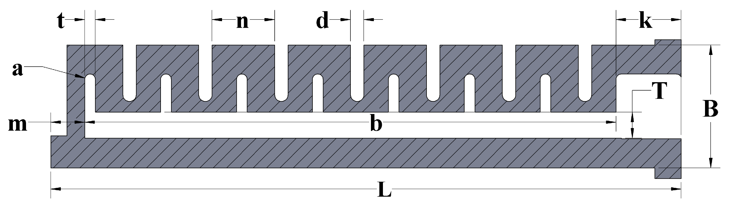
Figure 1. Soft finger manipulation design.
Actuators 14 00348 g001
Figure 2. Physics-driven reservoir computing architecture.
Actuators 14 00348 g002
Figure 3. Numerical simulation and experimental setup and comparison: (a) sensor placement for deflection measurement; (b) tracked tip as the output; (c) stress-strain curve for loading and unloading at 19 kPa; (df) FEM simulation results under the pressure of 4 kPa, 10 kPa, and 19 kPa, respectively; (gi) experimental recording under the pressure of 4 kPa, 10 kPa, and 19 kPa.
Actuators 14 00348 g003
Figure 4. Schematic section of the soft pneumatic finger design showing geometric parameters.
Actuators 14 00348 g004
Figure 5. (a) Soft finger fabrication process, (b) experimental setup overview, (c) embedded sensors on the flat surface, (d) tracked tip.
Actuators 14 00348 g005
Figure 6. Comparison between simulation and experimental data of tip trajectory prediction against a linear regression model. (a,b) experimental results at 10 kPa, and 19 kPa, respectively. (c,d) simulation results at 10 kPa, and 19 kPa, respectively.
Actuators 14 00348 g006
Figure 7. Quantitative comparison of tip trajectory metrics at varying pressures. (a) coefficient of determination ( R 2 ), (b) root mean square error (RMSE).
Actuators 14 00348 g007
Table 1. Soft finger geometric parameters.
ParameterValue (mm)
Total length (L)118.0
Chamber height (B)23.0
Inner chamber thickness (t)2.0
Air pathway height (T)5.0
Air pathway length (b)100.0
Fixed end length (k)12.0
Chamber length (n)12.0
Chamber offset (d)2.5
Extended wall length (m)6.0
Inner chamber radius (a)1.0
Disclaimer/Publisher’s Note: The statements, opinions and data contained in all publications are solely those of the individual author(s) and contributor(s) and not of MDPI and/or the editor(s). MDPI and/or the editor(s) disclaim responsibility for any injury to people or property resulting from any ideas, methods, instructions or products referred to in the content.

