


Optimal Design for Torque Ripple Reduction in a Traction Motor for Electric Propulsion Vessels

Abstract
1. Introduction
2. Design of an IPMSM for Electric Propulsion Outboard Systems
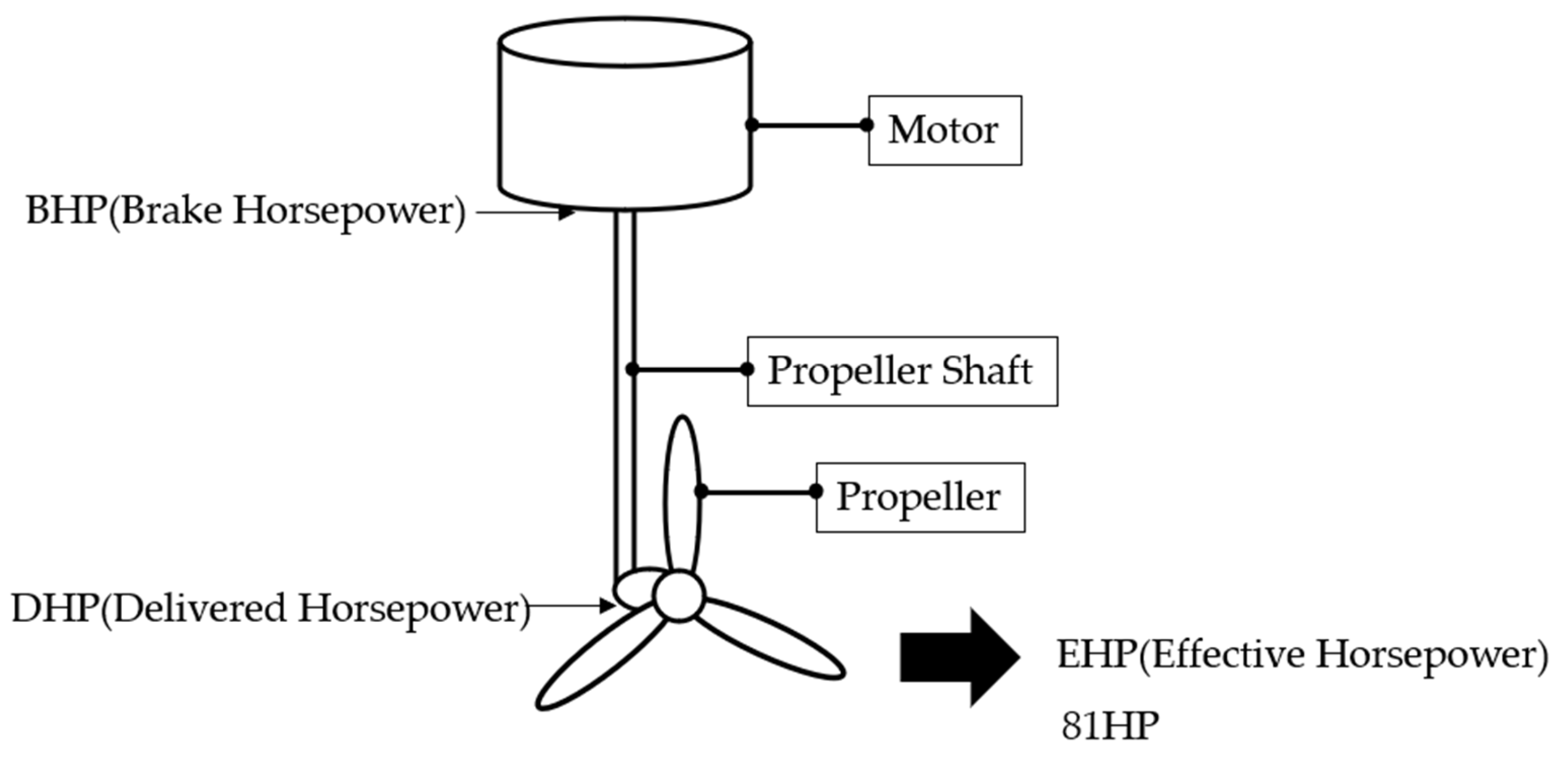
2.1. Calculation of the Required Output Based on the Cruising Speed
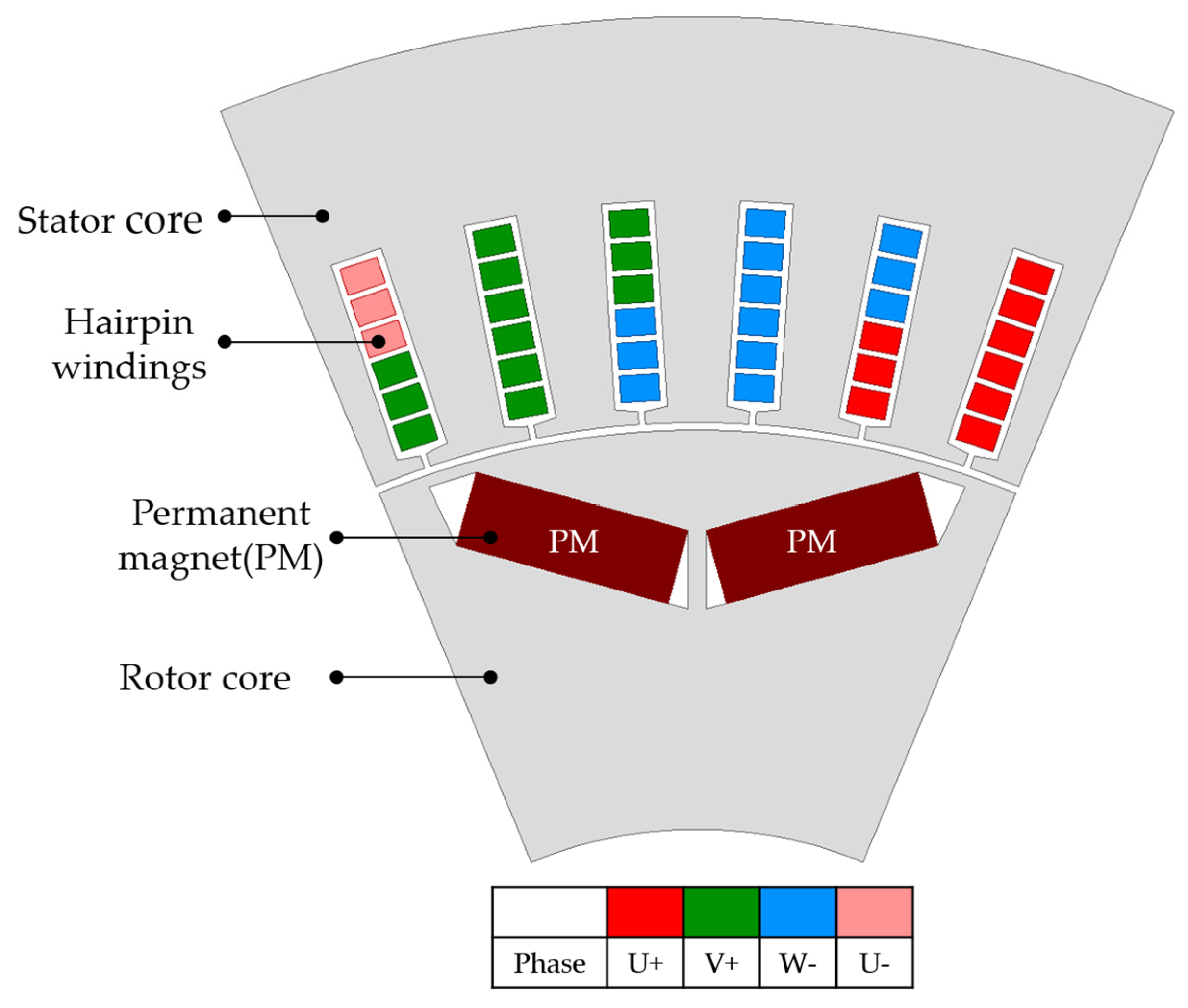
2.2. IPMSM Model Design
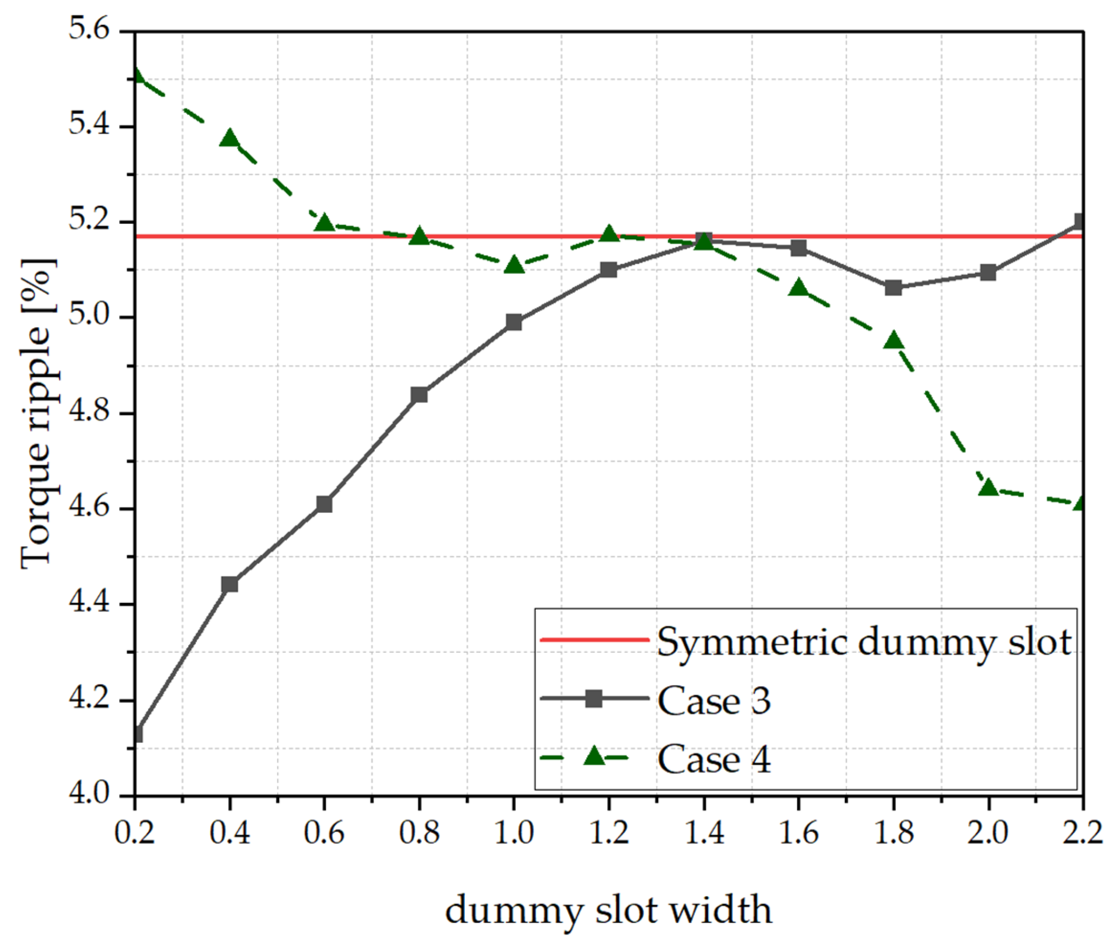
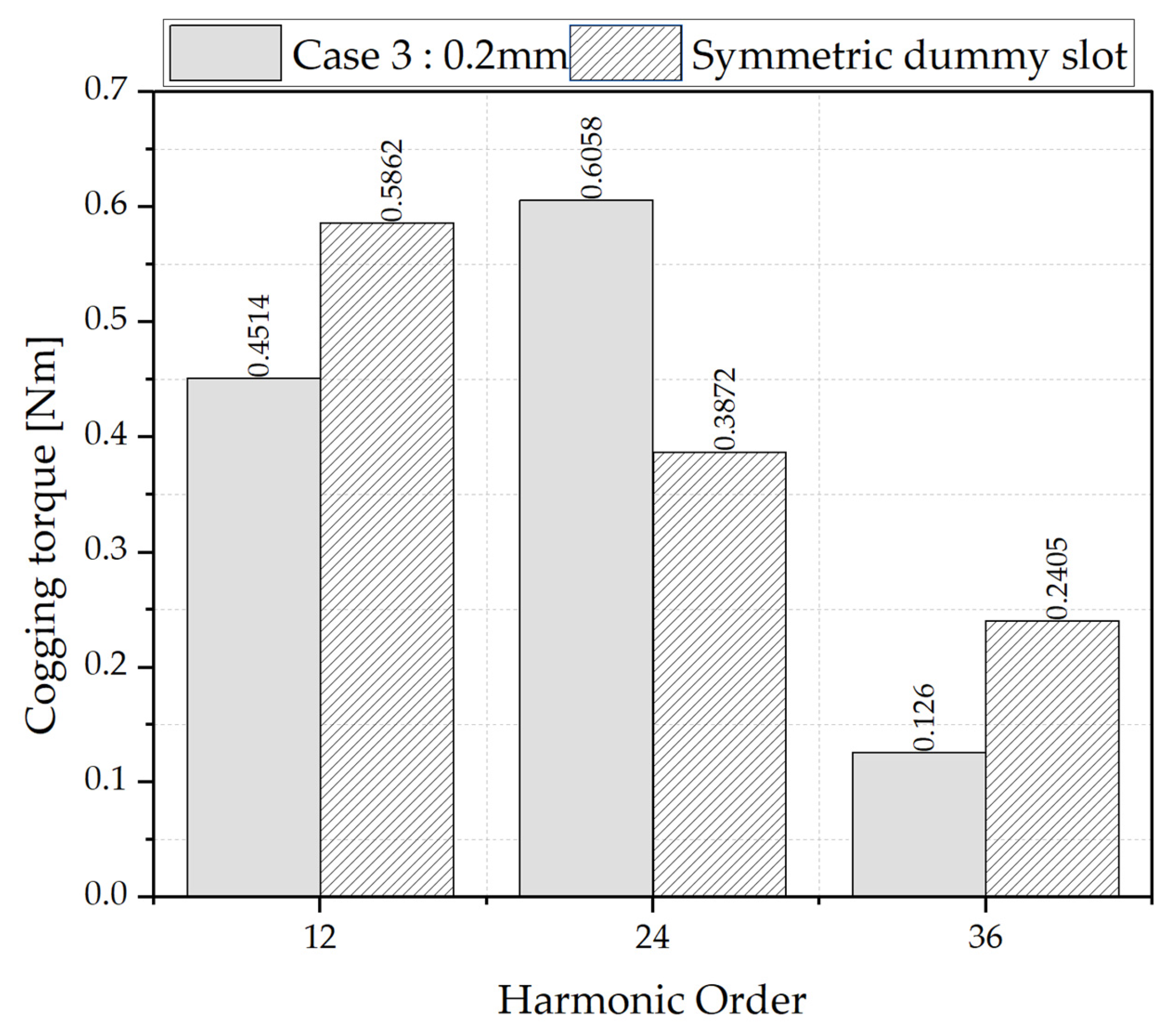
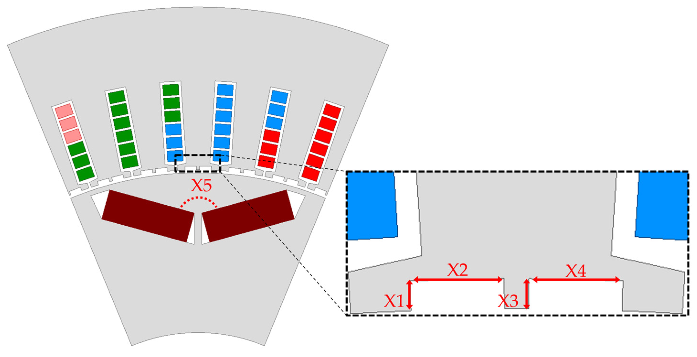
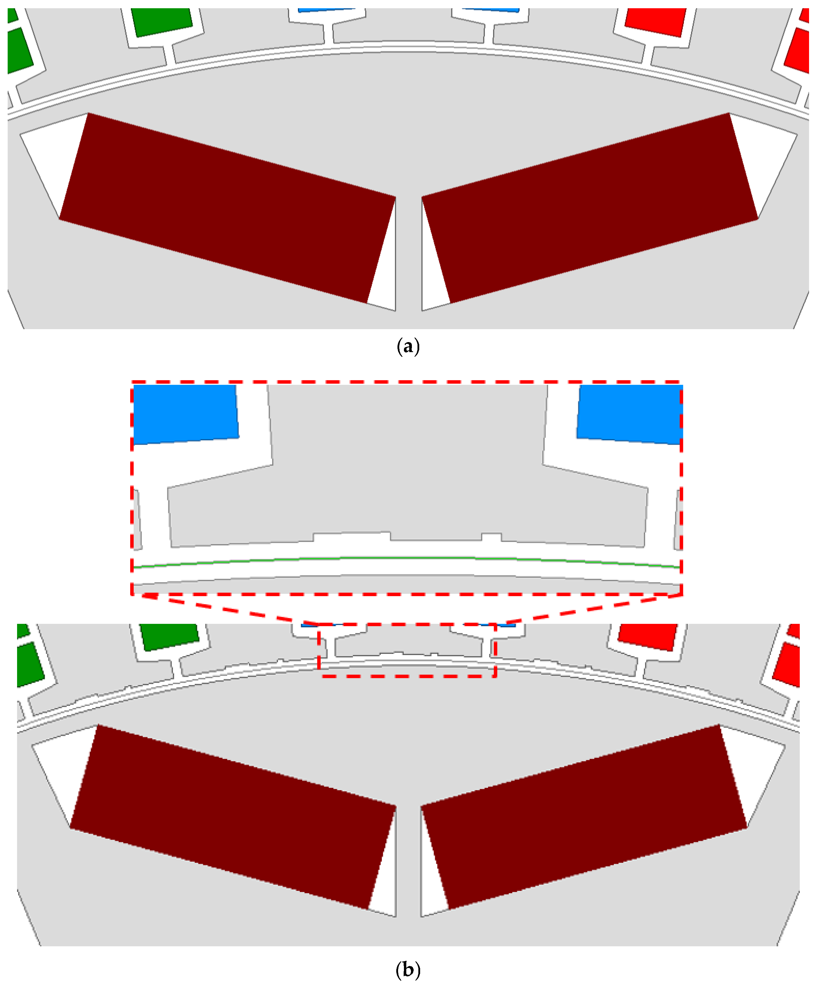
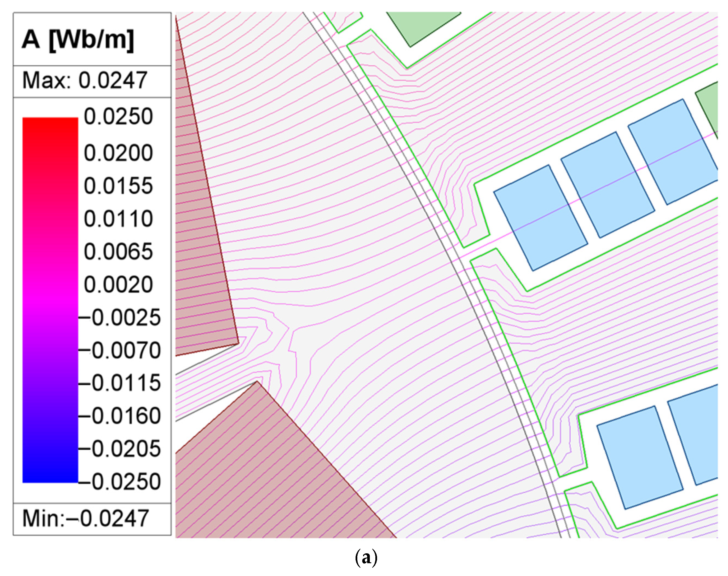
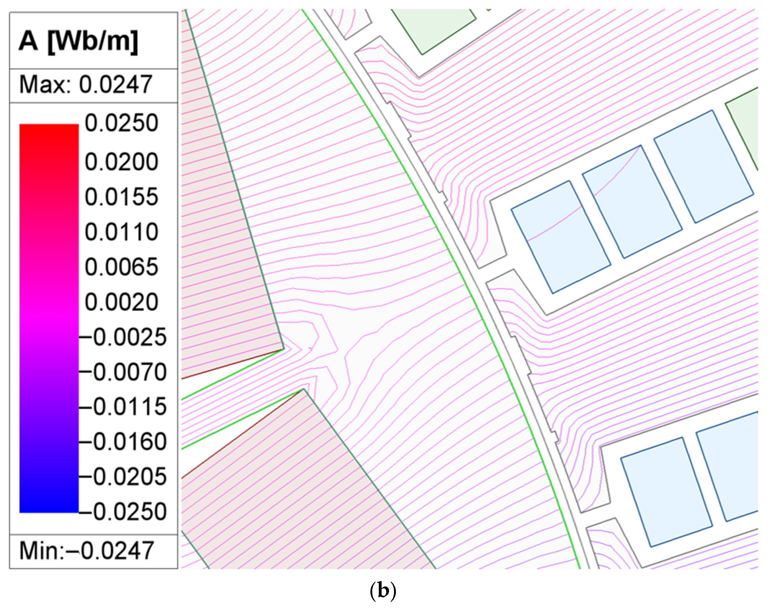
3. Concept and Design of the Asymmetric Dummy Slot
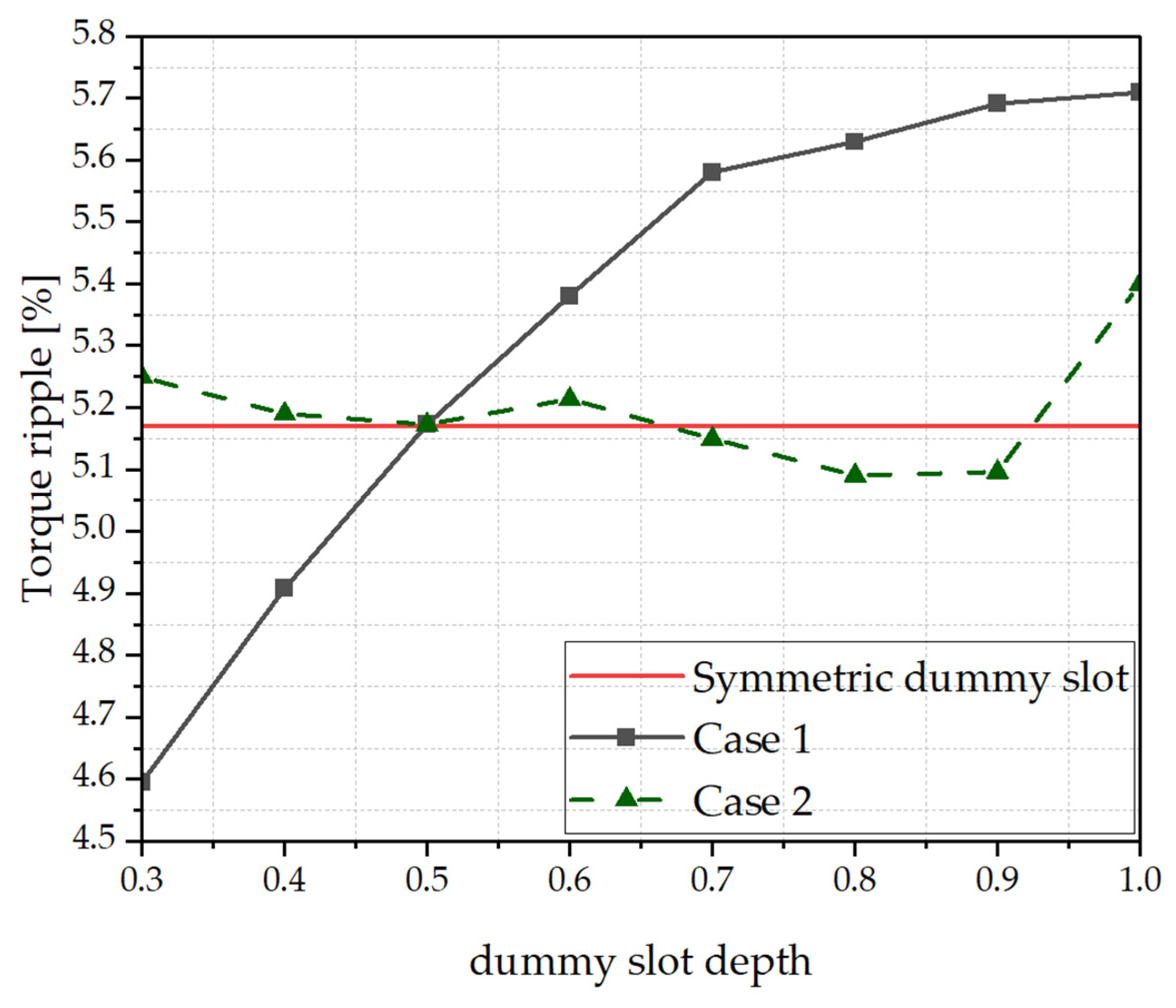
Design of the Asymmetric Dummy Slot
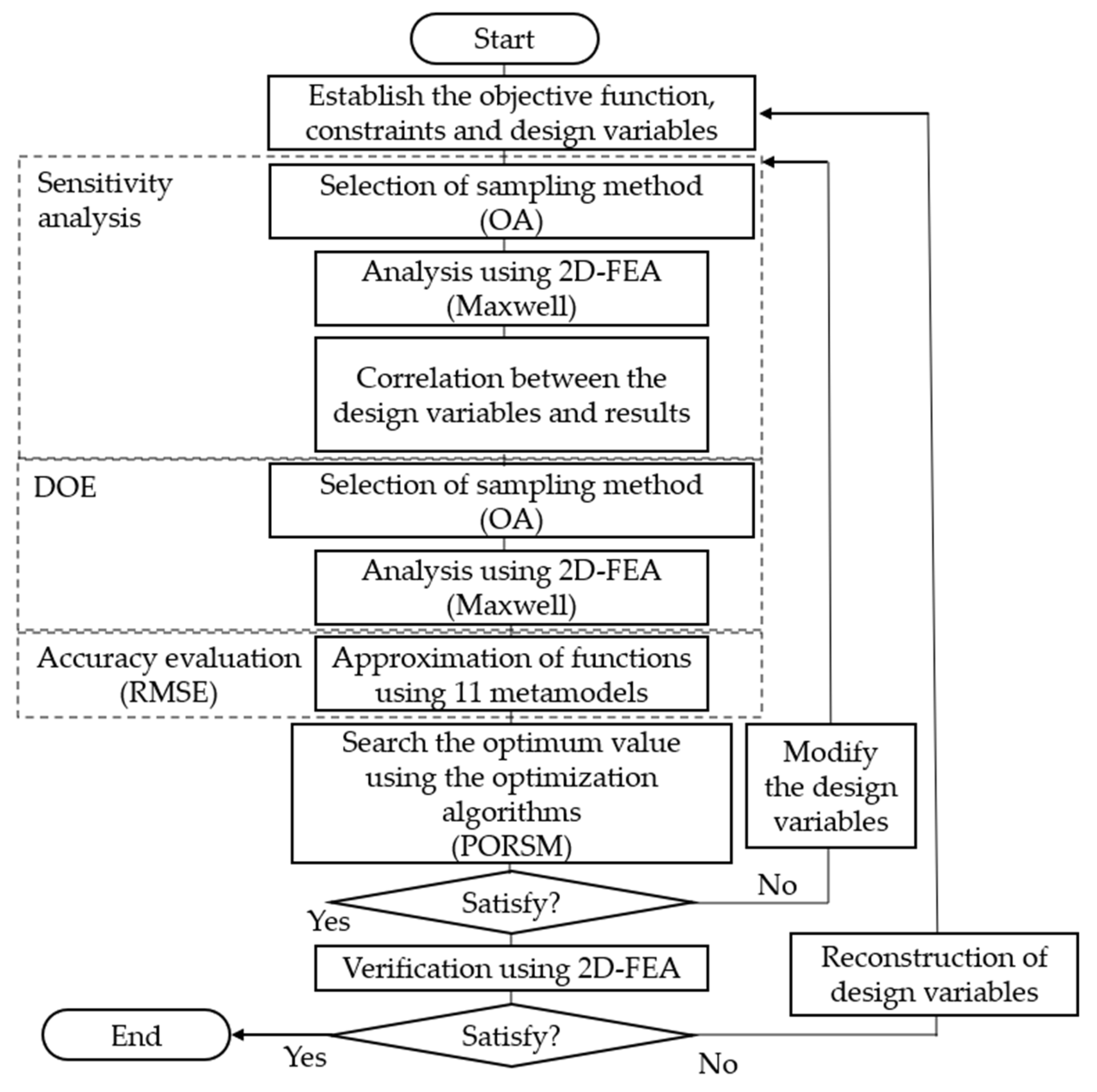
4. Optimal Design Using Asymmetric Dummy Slots and Metamodeling
4.1. Formulation of the Optimal Design Problem
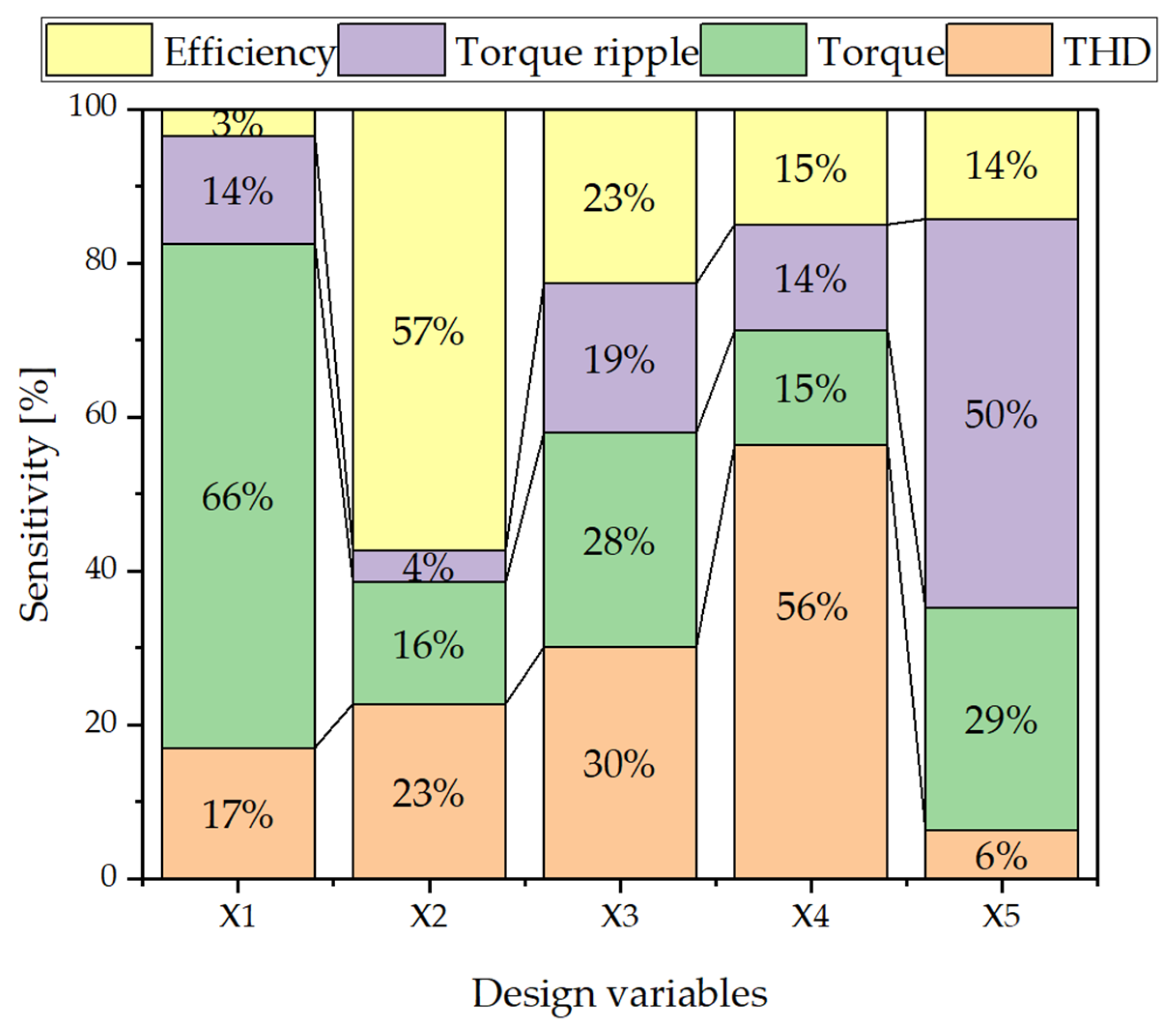
4.2. Sensitivity Analysis
4.3. Metamodeling
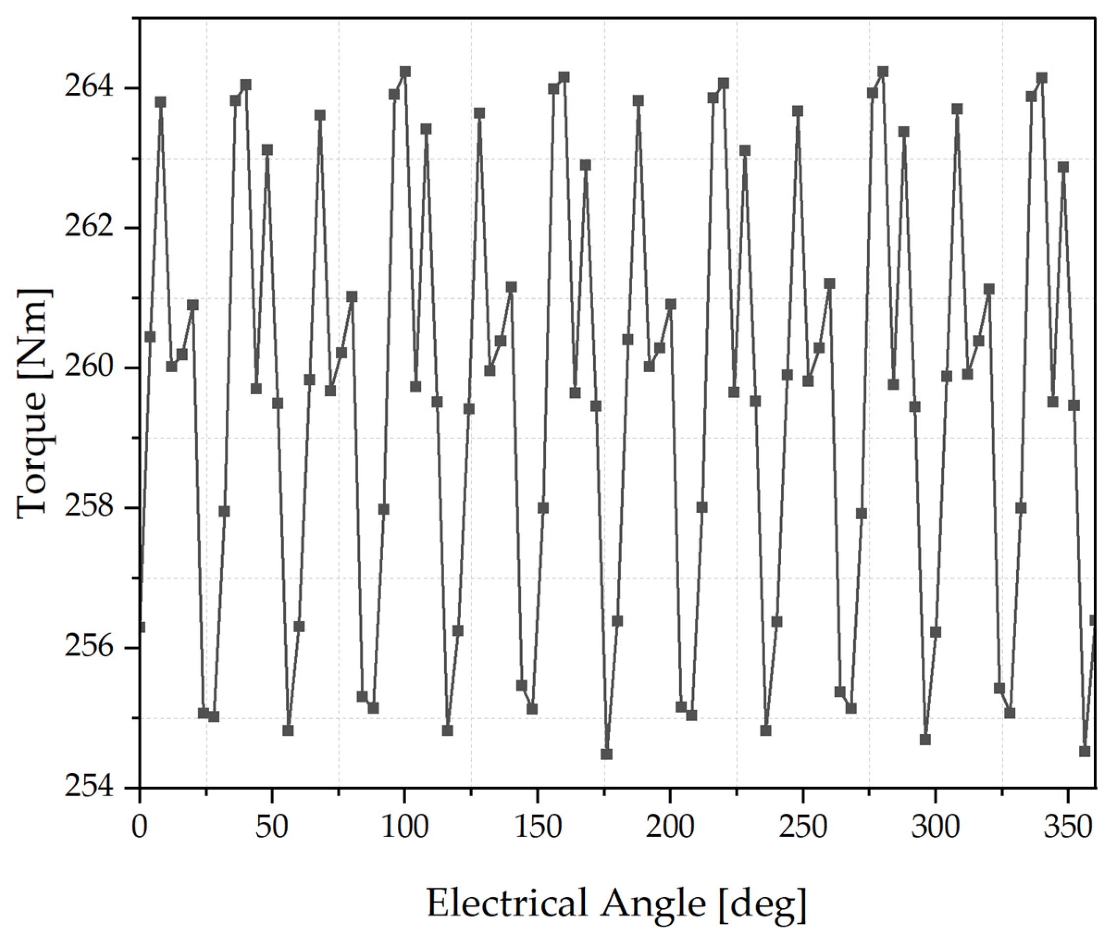
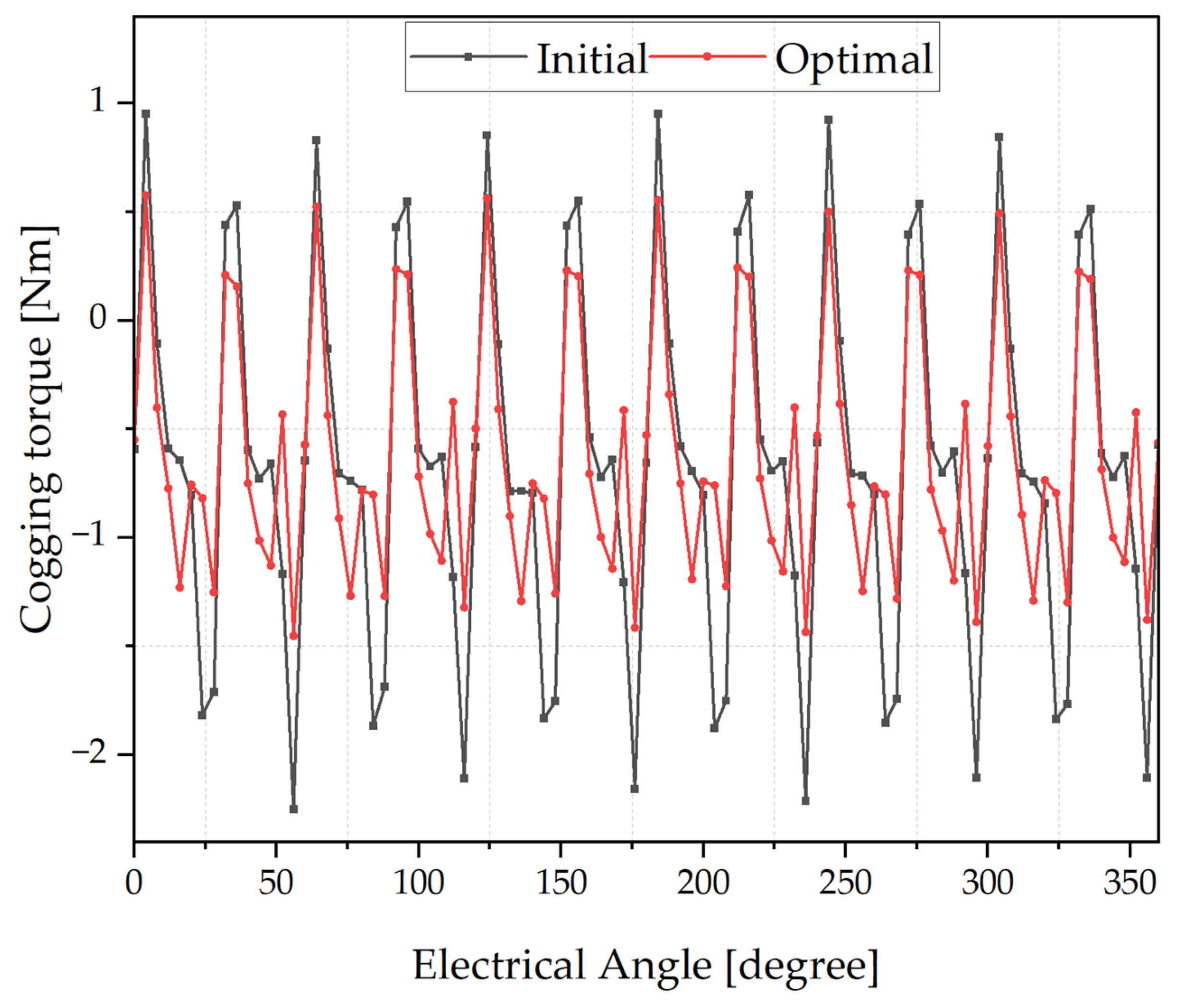
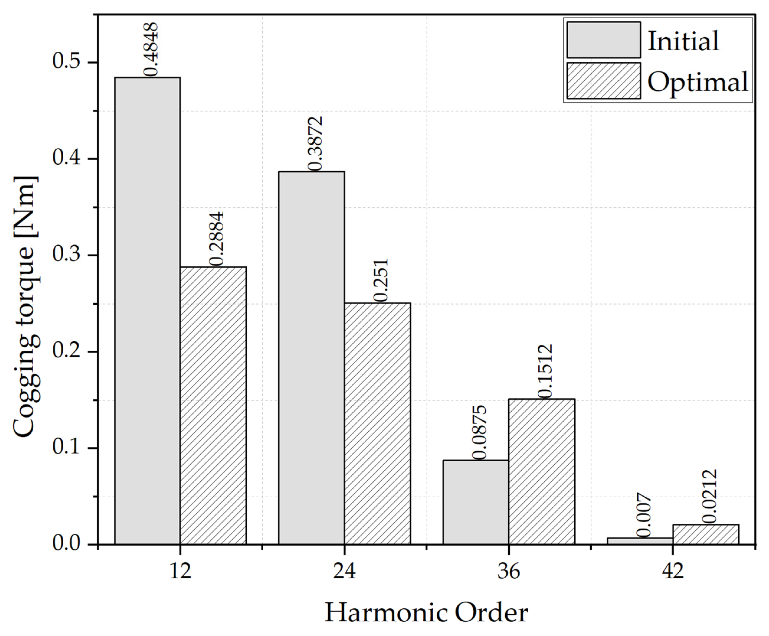
4.4. Optimal Design Results
5. Discussion
6. Conclusions
- A stator structure with two asymmetric dummy slots per stator slot (differing in width and depth) was proposed. This design demonstrated more effective torque ripple reduction compared with the conventional symmetric dummy slot configuration.
- A metamodel-based optimal design process was carried out, including the estimation of rated torque based on actual cruising speed conditions, taking into account efficiency, THD, and torque.
- The analysis confirmed that the optimized asymmetric dummy slot structure is not only a geometric modification but also a critical design element that significantly enhances harmonic suppression and reduces torque ripple.
Author Contributions
Funding
Data Availability Statement
Conflicts of Interest
References
- IMO(MEPC72). “Resolution MEPC.304(72).” Initial IMO Strategy on Reductin of GHG Emissions from Ships. Available online: https://www.imo.org/en/OurWork/Environment/Pages/Index-of-MEPC-Resolutions-and-Guidelines-related-to-MARPOL-Annex-VI.aspx (accessed on 21 May 2024).
- IMO (MEPC 80). “Revised IMO GHG Strategy.” 2023 IMO Strategy on Reduction of GHG Emissions from Ships. Available online: https://www.imo.org/en/MediaCentre/MeetingSummaries/Pages/MEPC-80.aspx (accessed on 21 May 2024).
- Lee, H. WTO Agreement on Fisheries Subsidies: Analysis and Perspective. Kyungpook Natl. Univ. Law J. 2023, 81, 295–323. [Google Scholar]
- University of Ulsan. The Development of Propulsion System of Small Electric Fishing Boat for Curtailment of Fuel Expense; Midterm Research Report; Ministry of Agriculture, Food and Rural Affairs (MAFRA): Sejong, Republic of Korea, 2011.
- Savitsky, D. Hydrodynamic Design of Planing Hulls. Mar. Technol. SNAME News 1964, 1, 71–95. [Google Scholar] [CrossRef]
- Savitsky, D. The Effect of Bottom Warp on the Performance of Planing Hulls. In Proceedings of the SNAME Chesapeake Power Boat Symposium, Annapolis, MD, USA, 15–16 June 2012. [Google Scholar]
- Bianchi, N.; Bolognani, S. Interior PM synchronous motor for high performance applications. In Proceedings of the Power Conversion Conference Osaka, Osaka, Japan, 2–5 April 2002; Volume 1, pp. 148–153. [Google Scholar]
- Yang, Y.; Castano, S.M.; Yang, R.; Kasprzak, M.; Bilgin, B.; Sathyan, A.; Dadkhah, H.; Emadi, A. Design and Comparison of Interior Permanent Magnet Motor Topologies for Traction Applications. IEEE Trans. Transp. Electrif. 2017, 3, 86–97. [Google Scholar] [CrossRef]
- Jung, D.S.; Kim, Y.H.; Lee, U.H.; Lee, H.D. Optimum design of the electric vehicle traction motor using the hairpin winding. In Proceedings of the IEEE 75th Vehicular Technology Conference, Yokohama, Japan, 6–9 May 2012. [Google Scholar]
- Zou, T.; Gerada, D.; La Rocca, A.; Moslemin, M.; Cairns, A.; Cui, M.; Bardalai, A.; Zhang, F.; Gerada, C. A comprehensive design guideline of hairpin windings for high power density electric vehicle traction motors. IEEE Trans. Transp. Electrif. 2022, 8, 3578–3593. [Google Scholar] [CrossRef]
- Chin, J.-W.; Cha, K.-S.; Park, M.-R.; Park, S.-H.; Lee, E.-C.; Lim, M.-S. High efficiency PMSM with high slot fill factor coil for heavy-duty EV traction considering AC resistance. IEEE Trans. Energy Convers. 2021, 36, 883–894. [Google Scholar] [CrossRef]
- Zhang, Y.; Xu, S.; Song, Y.; Qi, W.; Guo, Q.; Li, X.; Kong, L.; Chen, J. Real-time global optimal energy management strategy for connected PHEVs based on traffic flow information. IEEE Trans. Intell. Transp. Syst. 2024, 25, 20032–20042. [Google Scholar] [CrossRef]
- Qi, W.; Yang, J.; Zhang, Z.; Wu, J.; Lan, P.; Xiang, S. Investigation on thermal management of cylindrical lithium-ion batteries based on interwound cooling belt structure. Energy Convers. Manag. 2025, 340, 119962. [Google Scholar] [CrossRef]
- Qi, W.; Lan, P.; Yang, J.; Chen, Y.; Zhang, Y.; Wang, G.; Peng, F.; Hong, J. Multi-U-Style micro-channel in liquid cooling plate for thermal management of power batteries. Appl. Therm. Eng. 2024, 256, 123984. [Google Scholar] [CrossRef]
- Islam, M.S.; Mir, S.; Sebastian, T. Issues in reducing the cogging torque of mass-produced permanent-magnet brushless DC motor. IEEE Trans. Ind. Appl. 2004, 40, 813–820. [Google Scholar] [CrossRef]
- Choi, J.S.; Izui, K.; Nishiwaki, S.; Kawamoto, A.; Nomura, T. Topology optimization of the stator for minimizing cogging torque of IPM motors. IEEE Trans. Magn. 2011, 47, 3024–3027. [Google Scholar] [CrossRef]
- Dai, L.; Niu, S.; Gao, J.; Liu, K.; Huang, S.; Chan, W.L. Diverse slot-opening designs for cogging torque and performance optimization in PM machines. IEEE Trans. Transp. Electrif. 2025, 11, 8414–8426. [Google Scholar] [CrossRef]
- Nakano, M.; Morita, Y.; Matsunaga, T. Reduction of cogging torque due to production tolerances of rotor by using dummy slots placed partially in axial direction. IEEE Trans. Ind. Appl. 2015, 51, 4372–7382. [Google Scholar] [CrossRef]
- Zhao, G.; Hua, W.; Zhu, X.; Zhang, G. The Influence of Dummy Slots on Stator Surface-Mounted Permanent Magnet Machines. IEEE Trans. Magn. 2017, 53, 7207105. [Google Scholar] [CrossRef]
- Popescu, M.; Goss, J.; Staton, D.A.; Hawkins, D.; Chong, Y.C.; Boglietti, A. Electrical Vehicles—Practical Solutions for Power Traction Motor Systems. IEEE Trans. Ind. Appl. 2018, 54, 2751–2762. [Google Scholar] [CrossRef]
- Jung, S. Development of the Next-Generation Fishing Grounds Management Vessel Equipped with a Folding Propeller Protection Device; Final Research Report; Ministry of Trade, Industry and Energy: Seoul, Republic of Korea, 2019.
- Bae, J.-N. A Study on the Design Method of Permanent Magnet Synchronous Motor through Automatic Selection of Non-Magnetic Materials. Ph.D. Dissertation, Hanyang University Graduate School, Seoul, Republic of Korea, 2010. [Google Scholar]
- Mitra, U.; Rehman, S.U. ML-powered handwriting analysis for early detection of Alzheimer’s disease. IEEE Access 2024, 12, 69031–69050. [Google Scholar] [CrossRef]
- Okobiah, O.; Mohanty, S.; Kougianos, E. Fast design optimization through simple Kriging metamodeling: A sense amplifier case study. IEEE Trans. Very Large Scale Integr. (VLSI) Syst. 2014, 22, 932–937. [Google Scholar] [CrossRef]
- Rustam, F.; Reshi, A.A.; Ashraf, I.; Mehmood, A.; Ullah, S.; Khan, D.M.; Choi, G.S. Sensor-based human activity recognition using deep stacked multilayered perceptron model. IEEE Access 2020, 8, 218898–218910. [Google Scholar] [CrossRef]
- Hakim, M.; Choukri, S. Polynomial Metamodelling of Computer Simulation for UAV Design. In Proceedings of the 2024 4th International Conference on Innovative Research in Applied Science, Engineering and Technology (IRASET), Fez, Morocco, 16–17 May 2024; Volume 12, pp. 45678–45691. [Google Scholar]
- Xiao, H.; Pei, W.; Deng, W.; Kong, L.; Sun, H.; Tang, C. A Comparative Study of Deep Neural Network and Meta-Model Techniques in Behavior Learning of Microgrids. IEEE Access 2020, 8, 30104–30118. [Google Scholar] [CrossRef]
- Shi, Y.; Yang, C.; Wang, J.; Zheng, Y.; Meng, F. A Near-Real-Time Forecasting Model of High-Frequency Radiowave Propagation Factor Using ICEEMDAN and Bi-LSTM Methods. IEEE Trans. Antennas Propag. 2024, 72, 6032–6044. [Google Scholar] [CrossRef]
- Choi, J.H.; Kim, S.; Shin, J.M.; Lee, J. The multi-object optimization of switched reluctance motor using progressive quadratic response surface method. In Proceedings of the IEEE International Conference on Electrical Machines and Systems (ICEMS), Beijing, China, 9–11 November 2023; Volume 2, pp. 714–717. [Google Scholar]


| Item | Unit | Specification |
|---|---|---|
| Overall length | m | 10.10 |
| Length between perpendiculars | m | 7.78 |
| Breadth | m | 2.42 |
| Depth | m | 0.86 |
| Full-load draft | m | 0.32 |
| Gross tonnage (GT) | - | 1.78 |
| Contents | Unit | Required Specification | |
|---|---|---|---|
| Input | DC voltage | 800 | |
| Rated line current | 135 | ||
| Output | Continuous power | kW | 85 |
| Maximum speed | rpm | 4500 | |
| Base speed | rpm | 3200 | |
| Continuous torque | Nm | 256 | |
| Maximum efficiency | % | above 92 | |
| Parameter | Unit | Value |
|---|---|---|
| Core | - | 35JN440 |
| Permanent magnet | - | N50SH |
| Continuous current | 135 | |
| Current density | 15 | |
| Winding type | - | Hairpin |
| Wire dimension | mm | 3.6 × 2.5 |
| Outer diameter of stator | mm | 230 |
| Outer diameter of rotor | mm | 153.6 |
| Airgap length | mm | 0.7 |
| Design Variable | Unit | Lower | Initial | Upper |
|---|---|---|---|---|
| Slot width of left dummy (X1) | mm | 0 | 0 | 2.7 |
| Slot depth of left dummy (X2) | mm | 0 | 0 | 1 |
| Slot width of right dummy (X3) | mm | 0 | 0 | 2.7 |
| Slot depth of right dummy (X4) | mm | 0 | 0 | 1 |
| Inner angle between PMs (X5) | ° | 140 | 149.5 | 160 |
| Method | Torque | Efficiency | Torque Ripple | THD of the Back-EMF |
|---|---|---|---|---|
| EDT | 2.687532413 | 0.017803635 | 0.626197272 | 1.407876543 |
| KRG | 1.888395072 | 0.013437225 | 0.578776084 | 0.893450905 |
| MLP | 0.917006968 | 0.034439428 | 0.364933765 | 0.464566997 |
| PRG (BS) | 1.042229463 | 0.02034773 | 0.609251074 | 1.671807566 |
| PRG (FS) | 1.045633839 | 0.018921095 | 0.541693674 | 1.876204119 |
| PRG (FQ) | 1.501535645 | 0.02295552 | 0.601260253 | 1.679955251 |
| PRG (LR) | 1.045633839 | 0.018921095 | 0.541693674 | 1.876204119 |
| PRG (SC) | 3.184395327 | 0.032698192 | 1.011832783 | 2.098816844 |
| PRG (SQ) | 1.045633839 | 0.018921095 | 0.541693674 | 1.876204119 |
| RBF (Int) | 0.92366497 | 0.026957972 | 0.779280382 | 2.22014301 |
| RBF (Reg) | 3.06963340 | 0.078997461 | 0.804976201 | 0.84233359 |
| Item | Unit | Initial | Optimal (Metamodel) | Optimal (FEA) | Improvement Rate | |
|---|---|---|---|---|---|---|
| Design variables | X1 | mm | 0 | 1.55 | - | - |
| X2 | mm | 0 | 0.3 | - | - | |
| X3 | mm | 0 | 0.41 | - | - | |
| X4 | mm | 0 | 0.3 | - | - | |
| X5 | ° | 149.4 | 160 | - | - | |
| Objective function | Torque ripple | % | 4.61 | 1.51 | 1.7 | +2.91% |
| Constraints | Torque | Nm | 259.71 | 257.58 | 257.42 | −0.88% |
| THD of the back-EMF | % | 7.98 | 6.79 | 6.66 | +1.32% | |
| Efficiency | % | 96.91 | 96.95 | 96.95 | +0.04% | |
Disclaimer/Publisher’s Note: The statements, opinions and data contained in all publications are solely those of the individual author(s) and contributor(s) and not of MDPI and/or the editor(s). MDPI and/or the editor(s) disclaim responsibility for any injury to people or property resulting from any ideas, methods, instructions or products referred to in the content. |
© 2025 by the authors. Licensee MDPI, Basel, Switzerland. This article is an open access article distributed under the terms and conditions of the Creative Commons Attribution (CC BY) license (https://creativecommons.org/licenses/by/4.0/).
Share and Cite
Lee, G.-h.; You, Y.-m. Optimal Design for Torque Ripple Reduction in a Traction Motor for Electric Propulsion Vessels. Actuators 2025, 14, 314. https://doi.org/10.3390/act14070314
Lee G-h, You Y-m. Optimal Design for Torque Ripple Reduction in a Traction Motor for Electric Propulsion Vessels. Actuators. 2025; 14(7):314. https://doi.org/10.3390/act14070314
Chicago/Turabian StyleLee, Gi-haeng, and Yong-min You. 2025. "Optimal Design for Torque Ripple Reduction in a Traction Motor for Electric Propulsion Vessels" Actuators 14, no. 7: 314. https://doi.org/10.3390/act14070314
APA StyleLee, G.-h., & You, Y.-m. (2025). Optimal Design for Torque Ripple Reduction in a Traction Motor for Electric Propulsion Vessels. Actuators, 14(7), 314. https://doi.org/10.3390/act14070314