1. Introduction
Due to the advantages of small size, simple structure, and high power density, the brushless DC motor (BLDCM) has been widely used in industrial transmission, household appliances, and other fields [
1,
2,
3,
4]. Traditional single-phase diode rectifier input motor systems usually use large-capacity electrolytic capacitors in the dc-link circuit; however, the service life of electrolytic capacitors decreases significantly under extreme high temperature and high humidity environments, and about 60% of drive circuit failures are related to the electrolytic capacitor, which reduces the reliability of the motor drive system [
5,
6]. Compared with an electrolytic capacitor, the film capacitor allows a higher current ripple and has a longer lifetime, enhances reliability, and reduces the failure of the drive system [
7]. Hence, the electrolytic capacitor in the conventional dc-link circuit can be replaced by the film capacitor [
8,
9,
10,
11].
For the BLDCM drive with a single-phase rectifier, the dc-link circuit using a small capacitor in series with the IGBT scheme is mentioned in references [
12,
13,
14], and the topology circuit diagram of the brushless DC motor system with the small capacitor is shown in
Figure 1. In reference [
14], based on the topology circuit of
Figure 1, in each rectification cycle, when the capacitor voltage rises to the maximum value of the ac supply voltage, the capacitor charging vectors are applied at the same time, which will further increases the capacitor voltage, so that the motor input energy is not affected even if the dc-link capacitance is reduced.
However, when the single-phase rectifier BLDCM drives with reduced dc-link capacitance operate in regenerative braking mode, the dc-link capacitor is at risk of overvoltage. Because the dc-link capacitance in the drive system is reduced, and the diode rectifier is unable to realize the bidirectional flow of energy, the motor, during regenerative braking, can only feed energy back into the dc-link capacitor, and the capacitor voltage will rise rapidly. During regenerative braking, the copper loss of the motor can be harnessed to dissipate a portion of the motor’s mechanical energy. This serves to prevent the capacitor voltage from rapidly pumping and mitigates the occurrence of dc-link overvoltage [
9,
10].
Therefore, the implementation of an anti-overvoltage braking control scheme using hardware devices already available on the control system is an avenue worth exploring, which will expand the range of applications for drive systems with reduced dc-link capacitance.
In comparison to the electric mode, the braking mode represents another crucial operational state of the motor. During braking mode, the motor conducting phase current is in opposition to the phase back electromotive force (back-EMF), thereby generating an electromagnetic torque in the opposite direction of motor rotation. When the BLDCM operates in the electrical braking mode, the available electrical braking modes include regenerative braking, dynamic braking, and plug braking. Regenerative braking is a process whereby the mechanical energy of the motor system is converted into electrical energy and subsequently fed back to the energy storage elements of the power supply (e.g., batteries or supercapacitors) via a hardware circuit [
15,
16,
17,
18,
19]. Dynamic braking is a technique that involves connecting switches and braking resistors in series in the dc-link circuit. This is used to prevent the dc-link voltage from exceeding a threshold value set by the control system. When the voltage reaches this threshold, the switch is turned on, and the braking resistor absorbs the energy from the motor. This helps slow down the motor and prevent any damage from the excessive dc-link voltage. During plug braking mode, the motor can reverse the input voltage or introduce specific inverter control patterns to change the motor’s conducting phase sequence, generating a braking torque in the opposite direction of the motor rotation and achieving a rapid drop in motor speed [
20].
In the braking mode, the current flow circuit in the BLDCM drive is different from the normal electric mode, and the controllability of the braking torque is affected by the speed, so the control of the motor during braking is changed accordingly. Reference [
20] proposes a braking torque control scheme in the whole speed range of the motor. Dynamic braking is used in the high-speed range of the motor to utilize the braking resistor to absorb the energy generated by the motor and to avoid the occurrence of dc-link overvoltage. Meanwhile, plug braking is used in the motor’s low-speed range. The hybrid application of the two braking modes realizes the smooth control of the motor braking torque at the whole speed range. In reference [
21], for a hybrid energy storage system with a supercapacitor, it is proposed that combining the optimal selection of switching vectors, thereby realizing the recovery of braking energy and the control of braking torque.
In order to ensure the smooth and reliable operation of a small capacitor BLDCM system under braking mode, an anti-overvoltage braking torque control method is proposed in this paper. The relationship among the dc-link capacitance, the dc-link capacitor voltage, and the speed during regenerative braking is analyzed quantitatively, and the speed at which the regenerative braking is switched to the plug braking is obtained, which in turn consumes the capacitor energy to mitigate the phenomenon of overvoltage. Meanwhile, the braking torque controllability in different braking modes was analyzed, and the braking torque controllable speed interval was obtained. According to the obtained controllable speed interval of braking torque, a reference value of braking torque matching the motor speed is designed. The method proposed in this paper, on the one hand, makes use of the capacitor’s energy storage during regenerative braking and avoids the occurrence of capacitor overvoltage on the basis of the existing hardware of the system; on the other hand, it reduces the influence of the motor’s speed on the braking torque and takes into account the controllability of the braking torque, which ensures that the braking process of the motor is smooth and rapid.
The rest of this article is organized as follows.
Section 2 introduces the operation principle of the single-phase diode rectifier brushless DC motor drive with a small capacitance.
Section 3 analyzes the relationship among the dc-link capacitance, the dc-link capacitor voltage, and the speed during regenerative braking. In
Section 4, the corresponding relationship between the braking torque control performance and the speed is analyzed; thus, an anti-overvoltage braking torque control method is proposed. The experimental results to verify the proposed method are given in
Section 5.
Section 6 concludes this paper.
2. Single-Phase Diode Rectifier BLDCM Drives with Small Dc-Link Capacitance
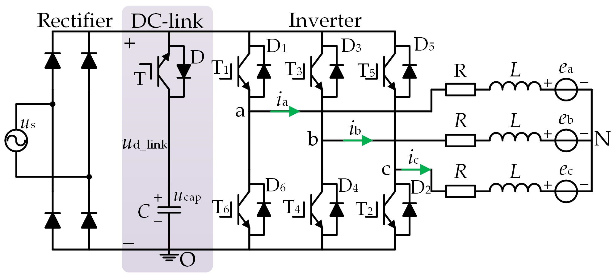
The equivalent circuit diagram of the single-phase diode rectifier BLDCM drives with the reduced dc-link capacitance is illustrated in
Figure 1. It primarily consists of a diode rectifier, dc-link circuit, inverter, and motor three-phase windings. The inverter is composed of six IGBTs, denoted as T
1−T
6. The voltage of the dc-link capacitor is denoted as
ucap, the instantaneous voltage of the ac power source is represented as
us, and the dc-link voltage is denoted as
ud_link. The phase inductance, phase resistance, and neutral point of the three-phase windings of the BLDCM are
L,
R, and N, respectively.
Figure 1 shows the direction of the current flow. According to the direction of the phase current, the three-phase windings can be redefined as positive conducting phase
p, negative conducting phase
n, and nonconducting phase
o (
p,
n,
o ∈ {a, b, c}). The actual current direction of the positive conducting phase aligns with the specified positive direction. Conversely, the actual current direction of the negative conducting phase is opposite to the specified positive direction. The mathematical model of the BLDCM in the two conducting phases is expressed as follows:
where
ep is back-EMF of the positive conducting phase,
en is back-EMF of the negative conducting phase,
ip is the positive conducting phase current,
in is the negative conducting phase current,
up is the positive conducting phase terminal voltage, and
un is the negative conducting phase terminal voltage.
For a single-phase diode rectifier BLDCM drive with small dc-link capacitance, the motor can achieve rated operation only if the input voltage complies with the rated voltage requirement. Taking the “
p+
n−” commutation period as an example, according to Equation (1), the phase current of the motor
IN =
ip = −
in, and the back electromotive force amplitude
E =
ep = −
en. Therefore, under the rated operating conditions of the motor, it is imperative that the dc-link voltage (
ud_link) adhere to the following equation:
where
ud_link is the dc-link voltage,
UpnN is the minimum value of dc-link voltage,
EN is the rated phase back-EMF amplitude, and
IN is the rated phase current of the motor.
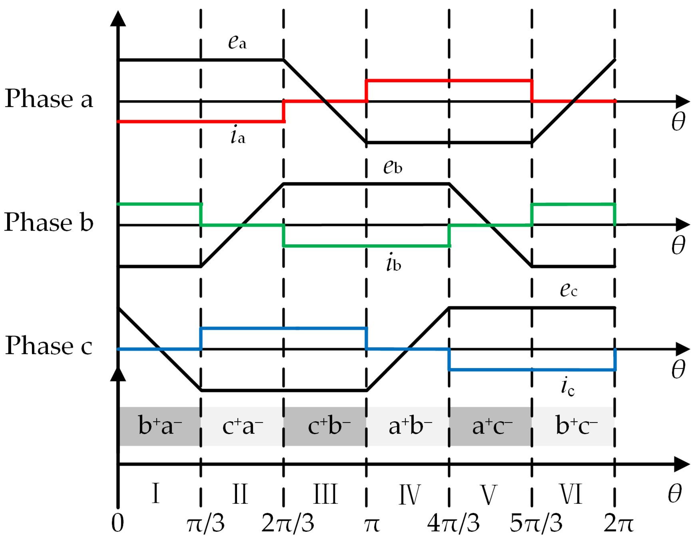
To meet the requirements of Equation (2), the rectifier output voltage |
us| can be divided into three zones based on a single rectification period
TR. Although the capacitance decreases, the motor input voltage always meets the rated voltage requirements. As depicted in
Figure 2, where the amplitude of the ac power supply voltage is
Um, the frequency of the ac power source is
f, and the rectification period is
TR. The logic for dividing the specific rectification period zone is as follows: Zone 1: |
us| ≥
UpnN where |
us| monotonically increases until
Um. Zone 2: |
us| ≥
UpnN where |
us| monotonically decreases until 0. Zone 3: |
us| ≤
UpnN.
The dc-link switch T is turned off in zone 1 and zone 2, while in zone 3, the switch T is turned on, and the capacitor alone supplies power to the motor. Subsequently, the capacitor voltage gradually declines until exiting zone 3. The dc-link voltage
ud_link is given by the following equation:
where T = 1 and T = 0 indicate the on and off states of the dc-link switch,
ucap is capacitor voltage, and |
us| is the rectifier output voltage.
For the BLDCM drive with reduced dc-link capacitance, there is only one zone 3 energy release process of the capacitor under the control of the dc-link switch transistor T. Therefore, by designing the appropriate capacitance, it is possible to ensure that the dc-link voltage
ud_link is always greater than
UpnN in a rectification period. This guarantees a smooth and continuous motor current. Assuming the capacitor voltage is precisely
UpnN at the end of the capacitor discharge in zone 3, to simplify the analysis, the process of capacitor voltage drop is approximated to be linear. Therefore, the dc-link capacitance is designed to satisfy the following equation:
where
Idc represents the average dc-link current, and
Um represents the amplitude of ac power supply voltage.
4. Proposed Anti-Overvoltage Braking Torque Control Method for BLDCM Drives with Small Dc-Link Capacitance
This section systematically analyzes the electrical braking torque controllability of a BLDCM drive with small dc-link capacitance, providing a basis for the proposed anti-overvoltage braking torque control method. The equivalent circuit diagrams for the electrical braking modulation mode of the BLDCM drives in sectors I, III, and V are shown in
Figure 4 and
Figure 5 below.
Figure 4a,b shows the regenerative braking OFF_PWM modulation pattern, and
Figure 5a,b shows the plug braking ON_PWM modulation pattern. S
pH, S
pL, S
nH, and S
nL indicate the switching state of positive conducting phase upper bridge arm IGBTs, positive conducting phase down bridge arm IGBTs, negative conducting phase upper bridge arm IGBTs, and negative conducting phase down bridge arm IGBTs. In the following analysis, the IGBT turn-on, turn-off, and duty cycle for one modulation period are denoted as “1”, “0”, and “
D”, respectively.
4.1. Controllability Analysis of Regenerative Braking Torque in Normal Conduction Period of the BLDCM
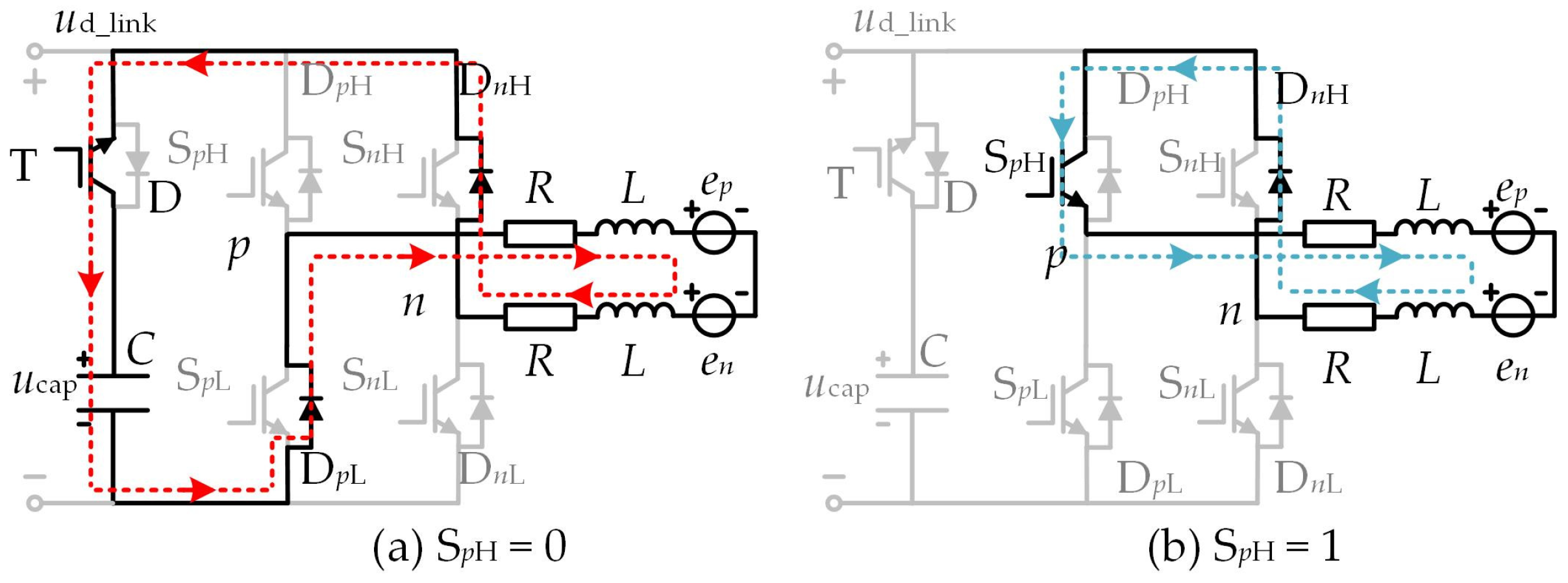
When the BLDCM drives with reduced dc-link capacitance adopt the regenerative braking OFF_PWM modulation pattern, the dc-link switch transistor T = 1. During this process, the capacitor can store a portion of the electrical energy converted from the mechanical energy. During an electrical cycle, when the rotor is located in an odd sector number (I, III, V), the switch transistor SpH, where the positive conducting phase p is located, operates with a duty cycle D. At the same time, all other switch transistors of the inverter are turned off.
When S
pH = 1, under the excitation of the line back EMF
epn, the positive conducting phase current
ip flows through S
pH and the antiparallel diode D
nH. Due to the presence of inductance in the phase winding, the winding inductance will store a portion of energy, forming a current path as shown in
Figure 4b.
When S
pH = 0, under the action of line back EMF
epn and inductor voltage, the positive conducting phase current
ip flows through the antiparallel diodes D
pL and D
nH and finally flows into the capacitor through the dc-link switch transistor T. At this time, the capacitor stores energy, forming another current flow path, as shown in
Figure 4a. During the normal conduction period of the BLDCM, in order to simplify the analysis, we ignore the effect of the antiparallel diode freewheeling of the nonconducting phase, and the line voltage equation of the two-phase winding conduction can be expressed as:
where
epn denotes the line back EMF.
When S
pH = 1, as shown in
Figure 4b, in order to simplify the analysis and ignore the voltage drop effect of the diode, the line voltage
upn = 0, combined with Equation (12), the rate of change of the positive conducting phase current
ip can be simplified as:
where
I0 is the initial value of the positive conducting current
ip and
I0 > 0. By setting Equation (13) to 0, the mechanical speed
ω0 can be derived as:
When S
pH = 1, combining Equations (13) and (14), the mathematical relationship between the change rate of the positive conducting phase current and speed in regenerative braking mode can be expressed as:
where
ω0 denotes the cut-off speed for the controlled rate of change of the positive conducting phase current when the conducting phase current reference is
I0, d
ip/d
t denotes the current change rate of the positive conducting phase during braking mode.
As illustrated in
Figure 4a, when S
pH = 0,
upn = −
ud_link. Similarly, according to the derivation process of Equation (12) to Equation (13), the current change rate of the positive conducting phase during the capacitor charging process can be expressed as:
Combining Equation (2) and Equation (16),
ud_link > 2(
keωrate +
RIN). So, when S
pH = 0, even if the motor starts braking from the rated speed
ωrate, d
ip/d
t < 0 satisfies any situation during the regenerative braking mode and is not affected by motor speed variations. Hence, in the capacitor charging and energy storage state illustrated in
Figure 4a, the current flowing through the motor windings will gradually decrease, consequently reducing the output braking torque as well. When the rotor position is in an odd sector (I, III, V), if the motor speed satisfies the inequality
ωm >
ω0. During a modulation cycle, the change rate of conducting phase current can be controlled by chopping S
pH, achieving controllable braking torque. However, when the motor speed satisfies the inequality
ωm <
ω0, whether S
pH is turned on or turned off, the change rate of conducting phase current is always less than 0 within a modulation cycle. Therefore, the motor’s braking torque output will continuously decrease. Similarly, when the rotor is located in an even sector (II, IV, VI), the negative conduction phase down bridge arm switch transistor S
nL chops with a duty cycle
D. At the same time, all other switch transistors in the inverter are turned off. According to the symmetry principle, similar results can be deduced as an odd sector (II, IV, VI).
Therefore, the controllable speed range for braking torque during regenerative braking is (ω0, ωrate]. If the motor speed remains within the speed range [0, ω0], the output braking torque will continuously decrease as the speed decreases due to the uncontrollable positive or negative rate of change in the conducting phase current.
4.2. Controllability Analysis of Plug Braking Torque in Normal Conducting Period of the BLDCM
When employing plug braking in the braking mode of the BLDCM drives with reduced dc-link capacitance, taking the ON_PWM modulation pattern as an example, the speed range of torque controllability for plug braking can be derived based on the torque controllability analysis method mentioned above for the regenerative braking OFF_PWM modulation pattern.
When using the plug braking ON_PWM modulation pattern, the switching logic of the dc-link switch transistor T is consistent with the control method in the electric mode described in Chapter 1. During one electrical cycle of the motor, when the rotor is in an odd sector number (I, III, V), the positive conducting phase switch transistor S
pH chops with a duty cycle
D, while the negative conducting phase switch transistor S
nL remains on. When S
pH = 1, as shown in
Figure 5a, the positive conducting phase current
ip flows through S
pH and S
nL under the combined action of line back EMF
epn and dc-link voltage
ud_link. When S
pH = 0, as shown in
Figure 5b, due to the presence of inductance in the winding, under the action of line back EMF
epn, the positive conducting phase current
ip flows through S
pL and the antiparallel diode D
pL.
To simplify the analysis and ignore the voltage drop effect of the diode, when S
pH = 1,
upn =
ud_link, combined with Equation (12), the change rate of the positive conducting phase current of the plug braking can be expressed as:
When SpH = 1, due to ud_link > 2(keωrate + RIN), dip/dt > 0 still holds even if the motor starts braking from the rated speed ωrate, independent of the change in motor speed. Consequently, the conducting phase current will rise, causing a corresponding increase in the plug braking torque.
When S
pH = 0, as shown in
Figure 5b,
upn = 0. Analogous analysis shows that the current change rate of the conducting phase is consistent with that shown in Equation (15). Therefore, when S
pH is turned off, the increase or decrease of the motor conducting phase current is related to the speed, which affects the controllability of the motor braking torque. According to the symmetry principle, using a similar analysis method as above, when the rotor is located in even sector numbers (II, IV, VI), the same analysis results as above can be obtained. It can be seen that the controllable speed range of the plug braking torque is [0,
ω0], and within this range, the deviation between the absolute value of the output braking torque and the reference of the braking torque is small.
4.3. The Proposed Overvoltage Braking Torque Control Method for BLDCM Drives
According to the above analysis, the BLDCM drives with reduced dc-link capacitance adopt the regenerative braking mode. Due to the limitation of capacitance, the dc-link capacitor will experience overvoltage problems at a certain speed point ωc during the regenerative braking process of the motor. To mitigate the phenomenon of overvoltage, the regenerative braking mode can be ended in advance, and the system can be switched to a plug braking mode to consume the energy of the capacitor and reduce the capacitor voltage. However, it should be noted that after switching to the plug braking, the performance of the plug braking torque control is related to the motor speed. Therefore, after switching to the plug braking, the reference of the braking torque needs to be redetermined.
When the motor performs regenerative braking with the braking torque
Te1, in a motor system with constant inertia and fixed capacitance
C, after the capacitor is charged to the maximum voltage
(UCM), the motor speed is
ωc at this moment, and then the system is switched to the plug braking, and the capacitor voltage will drop rapidly, which mitigate the phenomenon of overvoltage. Combining Equations (6)–(10), the rotational speed
ωc at the end of regenerative braking satisfies the following equation.
where
ωc denotes the motor speed when the capacitor voltage rises to its maximum value
UCM during regenerative braking.
By solving Equation (18), we can see that since
ωc > 0, ω
c can be deduced as:
According to Equation (19), when the capacitor voltage reaches UCM, the rotational speed ωc > (RI1/ke). Since the speed range of the controllable plug braking torque is [0, RI1/ke], and ωc > (RI1/ke), that is, the rotational speed ωc at the end of the regenerative braking exceeds the speed range of the controllable plug braking torque. If the braking torque reference remains at Te1, then the plug braking torque will not be controllable. Thus, to maintain torque control over the plug braking, it becomes necessary to increase the torque reference of the plug braking, which entails increasing the current reference, denoted as Iref. The requirement of Iref > (ωcke/R) needs to be met, thus expanding the speed range of the motor under the premise of controllable plug braking torque to ensure smoothness during the motor braking process.
5. Experimental Results and Analysis
In order to verify the feasibility of the proposed method above, a washing machine with a washing weight of 1 kg is built as an experimental platform, as shown in
Figure 6. The relevant parameters of the BLDCM system are calculated, and the parameters are listed in
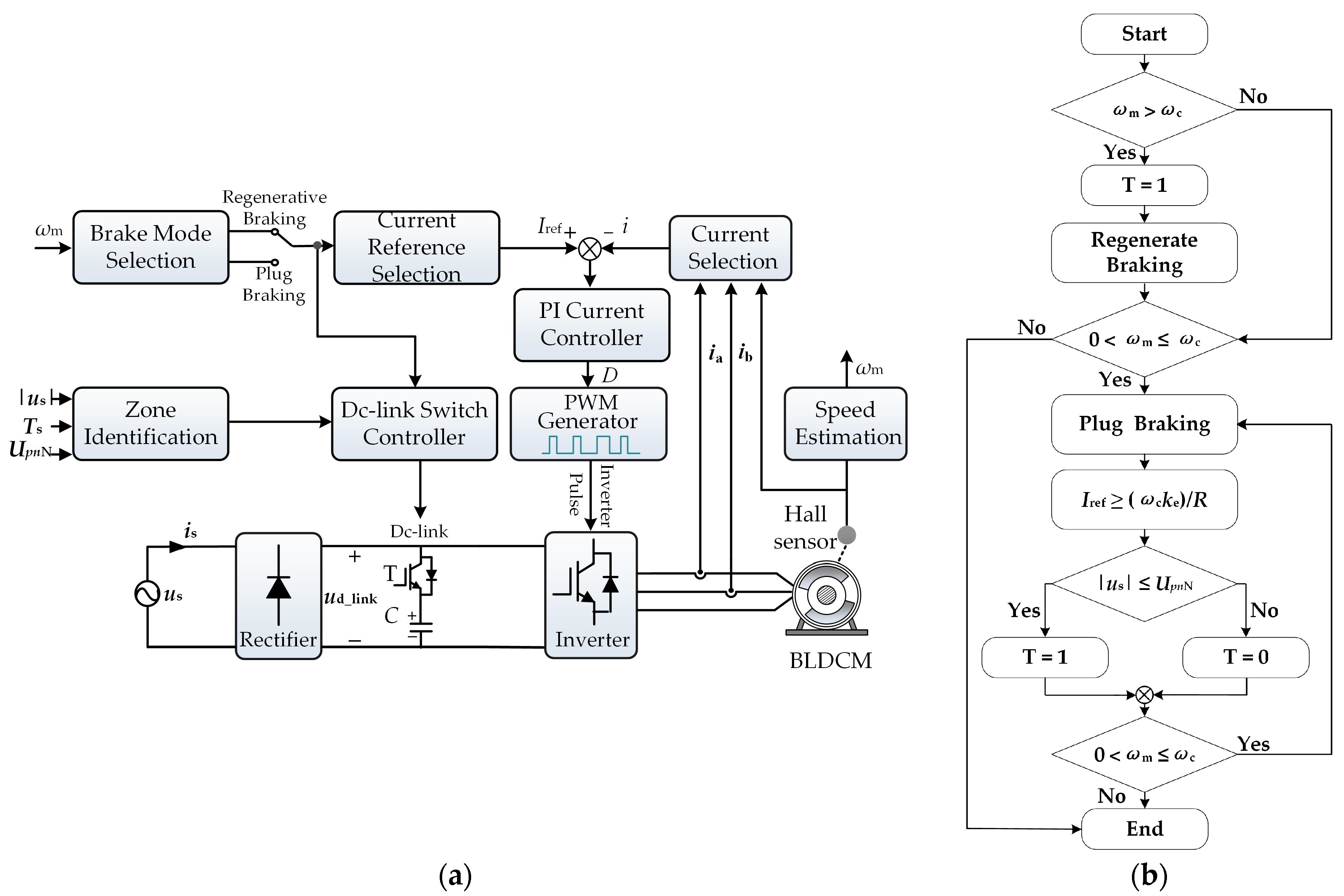
Table 1. The schematic diagram and flowchart of the proposed anti-overvoltage braking torque control method are shown in
Figure 7. As shown in
Figure 7a,
i denotes the non-commutated phase current, which is used as the feedback value for the PI current loop control. The proportional coefficient P of the PI controller is 7.0, and the integral coefficient I is 0.09.
The control method mainly consists of the main parts such as braking mode selection, zone identification, braking current reference selection, dc-link switch controller, and PI current controller. In the experiments, the proposed method in this paper uses DSP+FPGA as the control unit. According to the parameters listed in
Table 1, a film capacitor of 70 μF is used in the experiment, the braking mode switching speed
ωc = 66 rad/s (
nc = 630 rpm), the rated operating voltage of the capacitor is 450 V, the frequency of the ac power supply is 50 Hz, and the peak value of the power supply voltage
Um is 311 V. According to Equation (2), we can set
UpnN = 252 V, which can meet the requirements of the motor in the rated operating conditions.
In order to demonstrate the overvoltage problem caused by BLDCM drives with small dc-link capacitance in regenerative braking, only the regenerative braking approach is applied to the constructed washing machine experimental platform.
The washing machine was left empty, with no objects placed on it. When the speed is decelerated from 700 rpm to 0 rpm, the reference for the braking torque is −0.35 N·m. This indicates that the absolute value of the current loop reference is 0.26 A.
Figure 7 illustrates the overall control process. The experimental procedure involves first maintaining the washing machine motor speed at 700 rpm using the BLDCM electric control strategy with reduced dc-link capacitance, as described in
Section 1. Next, the operating mode of the washing machine should be switched to braking mode. The regenerative braking OFF_PWM modulation pattern is used in the braking control process. When the dc-link switch T is turned on during the regenerative braking process, the dc-link voltage
ud_link is equal to
ucap.
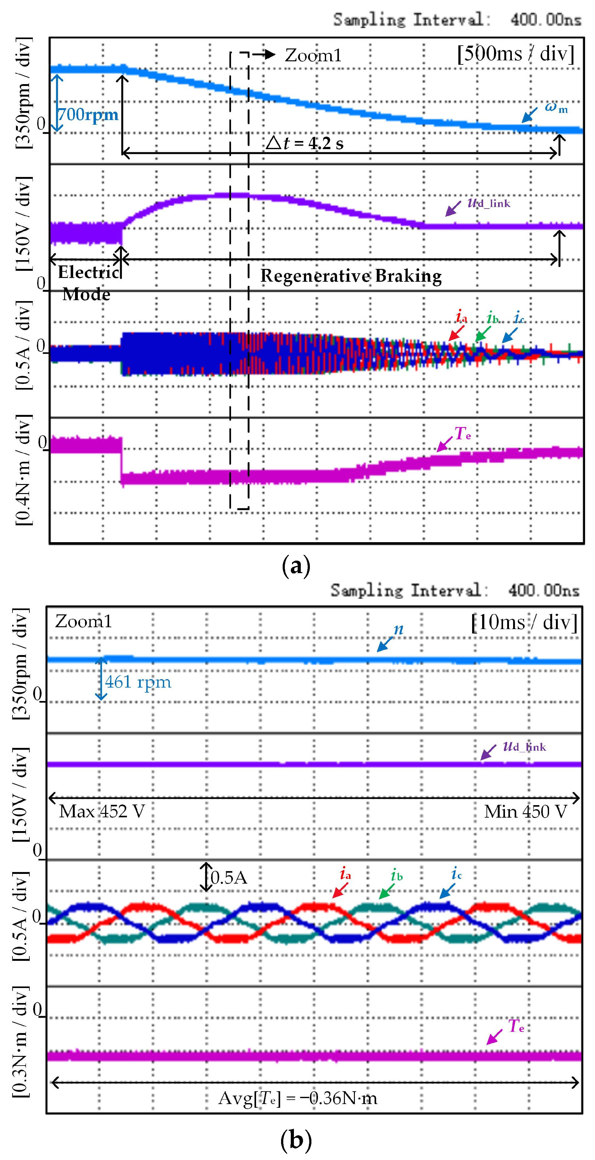
Figure 8 shows the experimental results, with waveforms representing speed, dc-link voltage, three-phase current, and electromagnetic torque from top to bottom.
Figure 8a shows that the washing machine braking process takes approximately 4.2 s from start to finish. The initial braking torque is smooth and controllable, and the capacitor voltage increases rapidly. The regenerative braking process causes the capacitor voltage to reach its maximum value. However, during the second half of the braking process, the amplitude of the motor’s three-phase current gradually decreases while the motor’s braking torque gradually diverges from the reference.
In
Figure 8b, the motor is still in the braking torque controllable region, but the maximum value of the capacitor voltage exceeds 450 V. If the rated operating voltage of the capacitor is less than 450 V, the capacitor may be degraded or even damaged, which will affect the reliability of the motor system. Therefore, to prevent capacitor overvoltage without requiring an additional mechanical braking device for the washing machine, this paper proposes an anti-overvoltage braking torque control method. Experimental waveform diagrams for this method are shown in
Figure 9. By setting the switching speed
nc = 630 rpm and ensuring that there is no load weighing 1 kg inside the washing machine, the dc-link voltage and torque variation characteristics of the motor system can be reflected in the experimental waveform in
Figure 9.
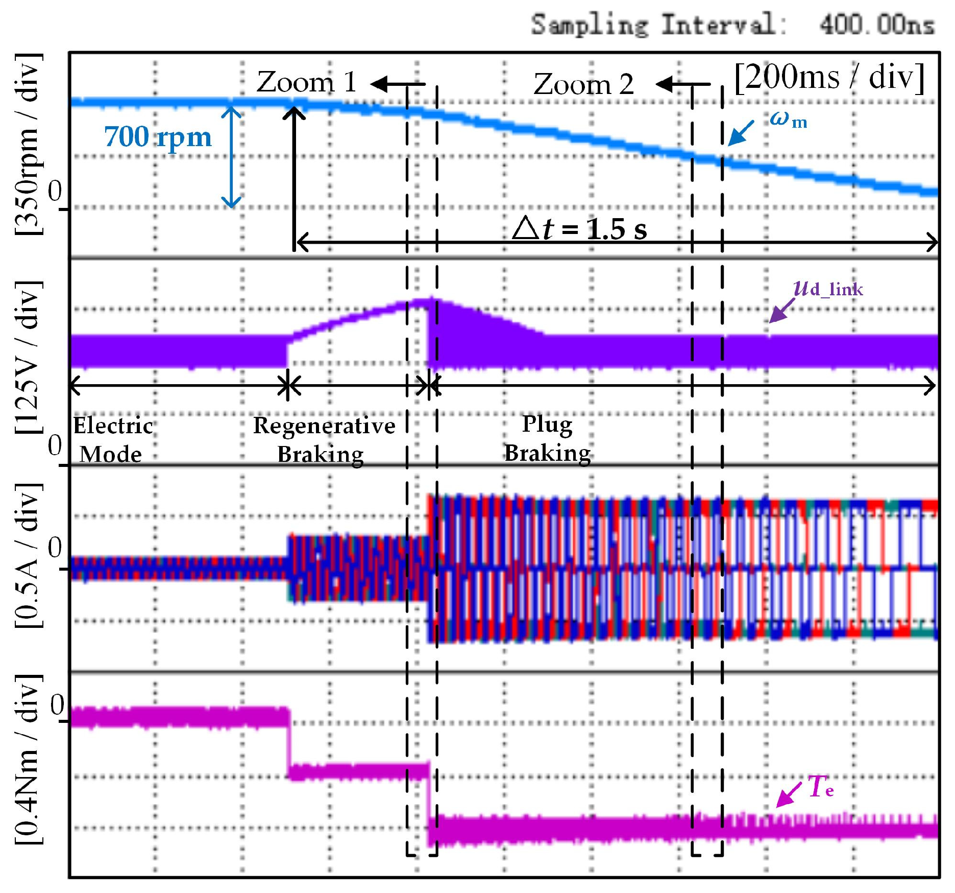
Figure 9 shows the experimental results of the proposed method of the washing machine under no-load conditions, in which the waveform graphs from top to bottom are the speed, three-phase current, dc-link voltage, and electromagnetic torque, respectively. During regenerative braking mode, the brake torque reference of the washing machine is −0.35 N·m. With the progress of regenerative braking, when the washing machine control system recognizes the speed
ωc and the braking mode changes to plug braking, the reference of plug braking torque is −0.83 N·m, and the modulation pattern is ON_PWM. As shown in
Figure 9, three operating modes exist in the system: electric mode, regenerative braking, and plug braking. At first, the electric mode adopts a control method for the BLDCM drives with reduced capacitance, after which the control mode of the washing machine changes to regenerative braking. At the same time, once the system recognizes the rotational speed as
ωc, it will switch to the plug braking mode to consume the stored energy of the capacitor during the regenerative braking process and avoid overvoltage of the capacitor.
As can be seen from
Figure 9, the washing machine takes approximately 1.5 s to decelerate from 700 rpm to 90 rpm during braking. This is a smooth and rapid braking process compared to the braking process shown in
Figure 8, which only uses the regenerative braking mode. As seen in
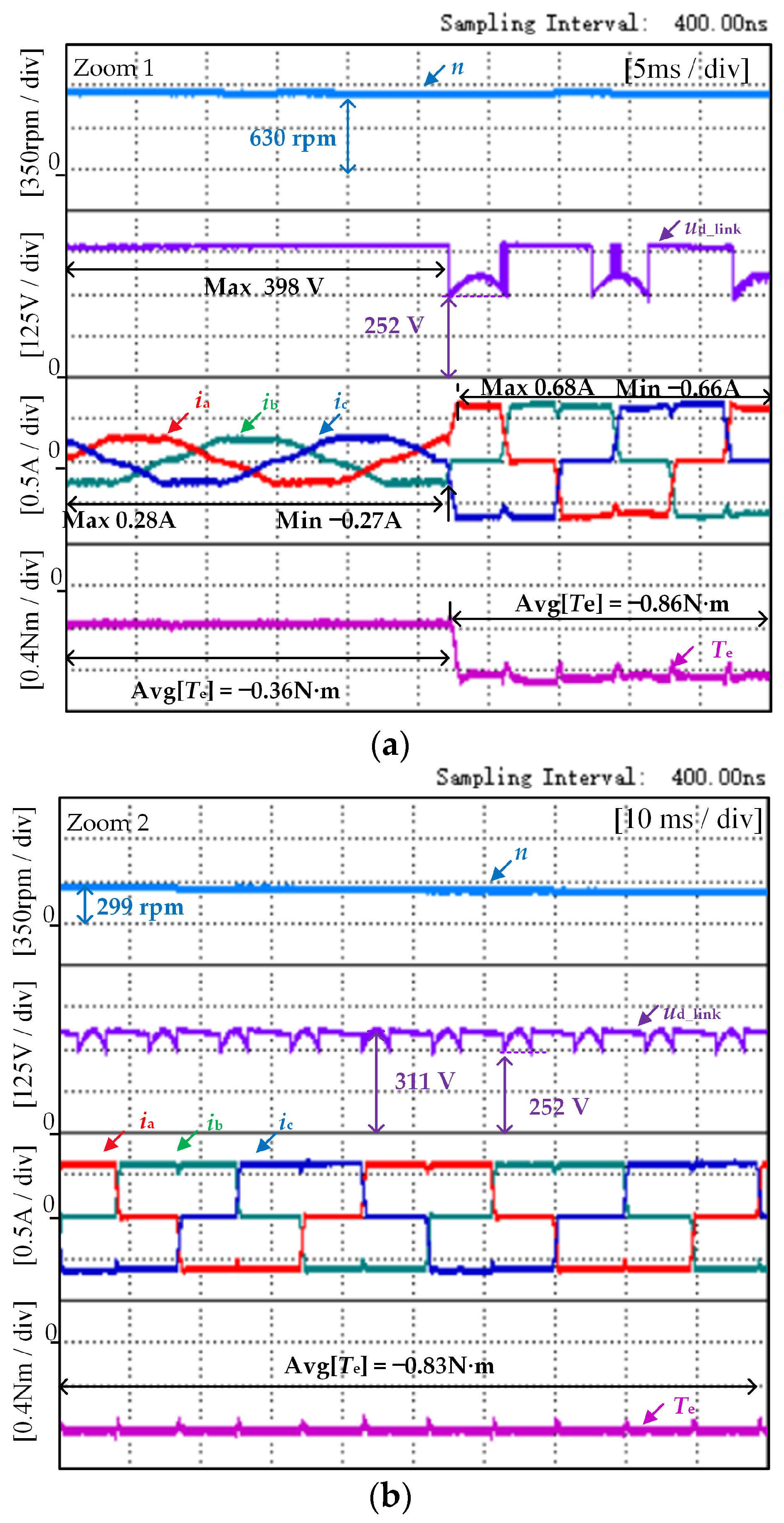
Figure 10a, the average value of regenerative braking torque is −0.36 N·m. The proposed method sets the switching speed of regenerative braking and plug braking at
nc = 630 rpm, at which time the maximum value of the capacitor voltage is 398 V, and then the braking mode is switched to plug braking. According to the previous analysis, the absolute value of the current loop reference converted from the regenerative braking torque reference of −0.35 N·m is not suitable for plug braking at this moment. Therefore, the absolute value of the plug braking current loop reference must be no less than 0.62 A; that is, the plug braking torque reference should be set to −0.83 N·m. As illustrated in
Figure 10a, the average value of plug braking torque is −0.86 N·m. As the braking process continues, as depicted in
Figure 10b, the average value of braking torque is −0.83 N·m. Hence, as the plug braking progresses, the final braking torque will tend to the set reference.
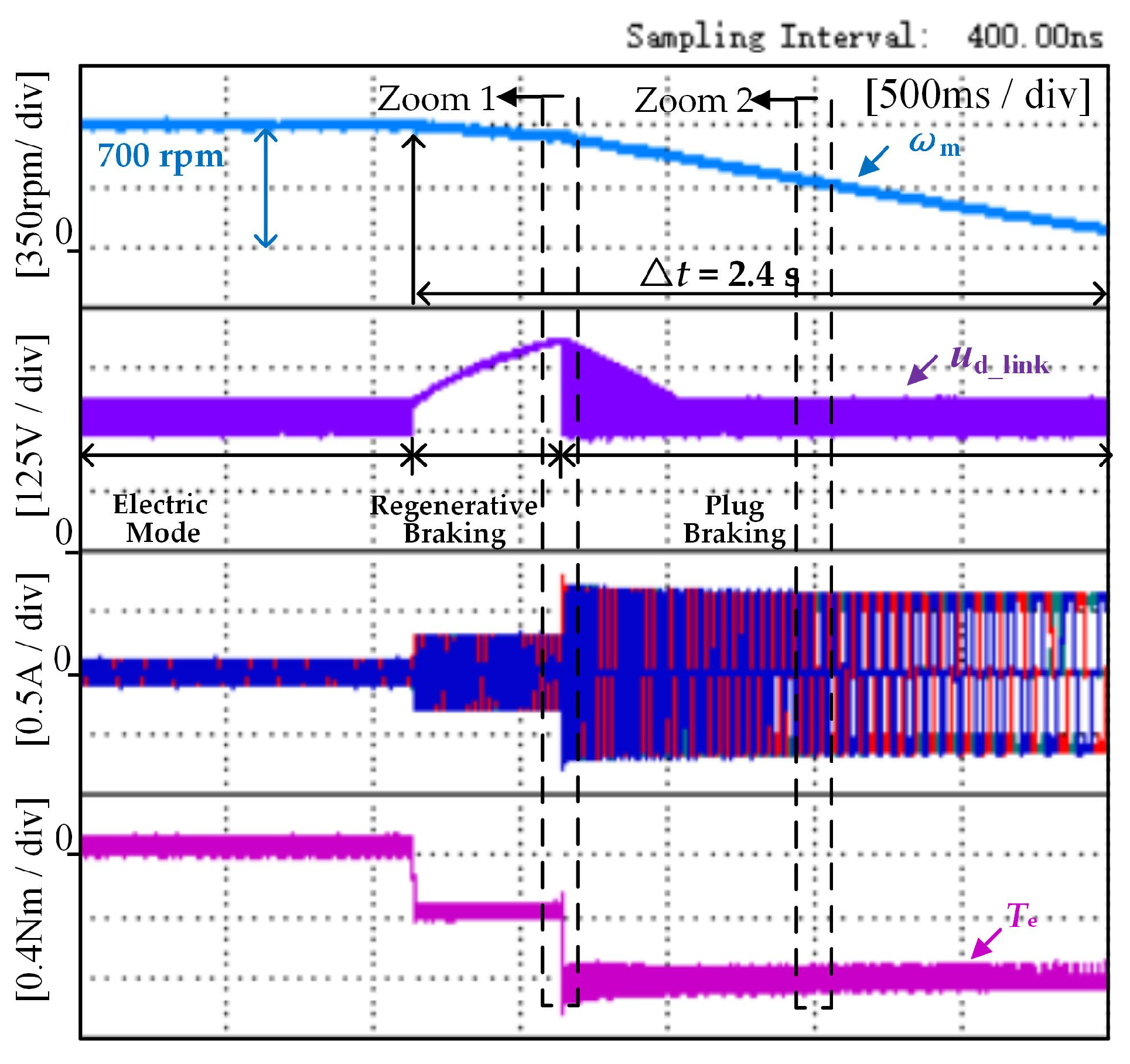
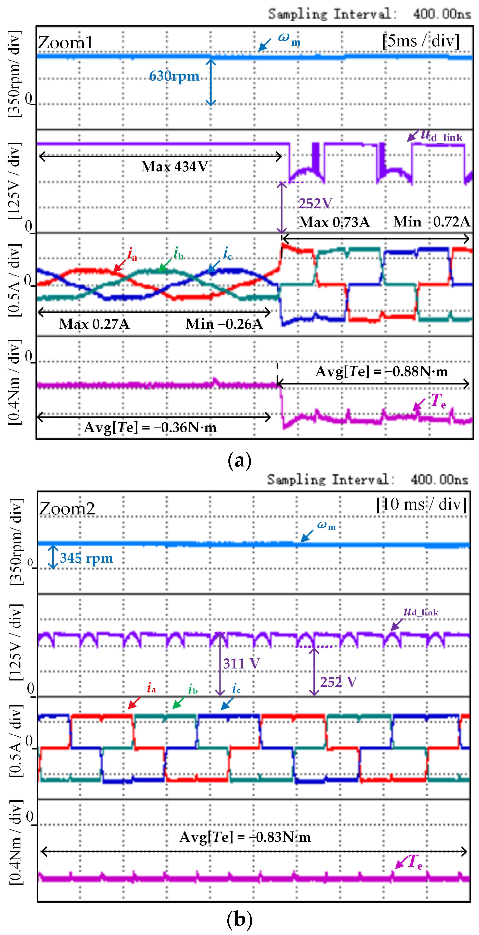
In order to simulate the actual operating conditions of the washing machine, a 1 kg load object was added inside the washing machine, and the other experimental conditions were consistent with those mentioned in
Figure 9. The results of the experiment are presented in
Figure 11.
Figure 11 presents the overall diagram of the system, which includes three operating modes. The washing machine takes approximately 2.4 s to brake when it decelerates from 700 rpm to 90 rpm, and the braking process remains stable. In
Figure 12a, the maximum value of the capacitor voltage at the braking mode switching speed
nc = 630 rpm is 434 V, which is still within the rated range of the capacitor voltage. As seen in
Figure 12b, the average value of braking torque reaches −0.83 N·m as the braking process proceeds, so the proposed method realizes prevention of capacitor overvoltage while taking into account the smoothness of braking torque.


