1. Introduction
The current airborne hydraulic power system is evolving towards high pressure and power to meet the development requirements of a large capacity and high efficiency of civil aircrafts [
1]. This trend increases the ineffective power of the system, resulting in a sharp rise in the system’s temperature, which leads to the accelerated aging of the medium, difficult sealing of the system, and other problems that will seriously affect the safety of flight control. Therefore, an intelligent aviation hydraulic system that can realize timely matching with the load effectively solves this problem [
2]. As the core component of the airborne hydraulic power system, the current airborne pump is mainly the constant-pressure variable displacement pump, and its rated pressure is the maximum pressure during flight, which causes much power to be wasted in other flight phases. Therefore, the intelligent pump system, which can work in different modes according to the flight conditions, effectively solves aircraft hydraulic systems’ inefficient power consumption and temperature rise [
3].
The intelligent pump is a pump source system that uses a microcontroller to intelligently adjust the output flow rate and pressure of the hydraulic pump. In order to realize the timely perception of the system status, it is necessary to install the pressure, flow rate, temperature, and other sensors on the pump. The controller applies intelligent algorithms to adjust the displacement or rotation speed of the pump according to the pressure and flow rate instructions generated by the flight control processor, and finally realizes the best matching of the pump’s output performance with the load to achieve the goal of saving energy [
3]. When the actuators of the flight control system are subjected to a constant load, a constant output force needs to be generated, and the intelligent pump can work in a constant-pressure mode. When the actuators need to output constant speed to drive the rudder surface, a stable flow rate is required, and the intelligent pump can work in a constant-flow mode. When the working conditions of the actuators are complex and changeable, the output force and speed need to change continuously with the needs of the load and rudder surface movement, and the intelligent pump can work in the mode of pressure and flow change. The type selection and structural design of aviation hydraulic pumps need to match the needs of aviation hydraulic systems. Because the working pressure of a rotodynamic pump is low, the flow rate and pressure affect each other, and its working performance is greatly affected by the viscosity of the liquid; it is not suitable for aviation hydraulic systems, so almost all the research on aviation hydraulic pumps use positive displacement pumps. In the category of positive displacement pumps, compared with a gear pump and vane pump, a swash plate pump is widely used in aviation hydraulic systems because of its compact structure, high working pressure, high power-to-weight ratio, and ease of achieving continuously variable displacements. Scholars have designed a variety of working principles and structural forms to meet the needs of intelligent pumps [
4,
5,
6,
7,
8]. In these schemes, the electro-hydraulic intelligent pump uses the auxiliary pump as the oil source of the servo valve, which can achieve a stable oil source pressure. Still, the additional pump source will increase the volume and weight while making the structure complex and reducing the reliability of the aviation pump.
The self-supplied electric hydraulic intelligent aviation pump scheme avoids these problems well. Based on the current widely used aviation constant-pressure variable displacement pump, the scheme only needs to replace the spool of the compensation valve and integrate the servo valve into the pump shell, which is connected to the control piston chamber and then directly drives the swash plate to adjust the displacement. The main difference with the existing aviation smart pump is that this scheme’s oil source for the servo valve comes from the pump outlet, rather than a separate auxiliary pump for oil supply. In contrast, this solution avoids the additional volume and weight of the auxiliary oil source. It is compact in structure and easy to implement based on a constant-pressure variable displacement pump. It still maintains a high power-to-weight ratio and reliability.
To investigate the output performance of variable displacement piston pumps, it is necessary to establish a mathematical model based on the analysis of the principles of its key components to investigate the influence of parameters on the performance. Wu et al. established a theoretical model of the piston cavity that includes fluid compression properties and leakages to reduce the outlet flow pulsation of the high-pressure piston pumps. They proposed a parametric design that optimizes the valve plate’s transition region structure to minimize the outlet flow ripple [
9]. Fang et al. proposed an improved variable displacement piston pump model to investigate the influence of the variable displacement mechanism on swash plate oscillation. They suggested some feasible methods to reduce swash plate vibration by investigating the role of structural parameters, such as the volume of the outlet chamber and the offset distance of the actuating piston on swash plate vibration [
10]. Pan et al. established a theoretical model for the outlet flow pulsation of a constant-power variable displacement piston pump, which considers the vibration of the swash plate, flow leakage, and valve dynamic characteristics. The theoretical model of flow pulsation was used to study the effect of swash plate vibration on the flow and pressure pulsation at the pump outlet. Valve plate optimization based on the theoretical model was also studied by taking the amplitude of the instantaneous outlet flow ripple as the optimization objective function [
11]. Chen et al. investigated the causes of the pressure drop of the aeronautical hydraulic systems in the cruise state by setting up a simulation model of a double-tier constant-pressure controlled variable displacement piston pump. They also studied the effects of the variable pump’s piston number, spring stiffness, and pressure drop. The effects of parameters such as the number of pistons, spring stiffness, and the spool’s mass on the pressure drop were also investigated [
12]. Kumar et al. explored the effects of hydraulic mineral oil on the output power, piston chamber pressure, and leakage flow in the piston cylinder at different temperatures through the established nonlinear mathematical model of axial piston pumps [
13]. Ishita et al. analyzed the components of swash plate swiveling torque using a fixed displacement pump’s mathematical model, determined the torque values at maximum and minimum flow conditions, and designed the compensator cylinders. The effect of eccentricity on the performances of the fixed and variable displacement pumps was also investigated by simulation [
14].
The above research mainly focuses on the performance and critical structural parameters of constant-pressure variable displacement piston pumps. However, in contrast, the self-supplied smart pump can not only actively regulate the pump outlet pressure by the servo valve, but also, importantly, the servo valve’s oil source comes from the pump outlet and does not need to add an auxiliary pump source. This makes the output characteristics of the self-supplied smart pump very different from those of constant-pressure variable displacement pumps and other servo pumps. Kemmetmuller et al. designed a pressure control strategy for the self-supplied variable displacement axial piston pumps used in injection molding machines. They developed a load estimator combined with feed-forward and feedback strategies, achieving high-dynamic-pressure tracking under an unknown load [
15]. Mu et al., for the pressure control task of self-supplied variable axial piston pumps, using the smooth hinge function provided a control strategy consisting of feedforward and feedback control, compared to switching feedforward control, which can avoid the issues that occur when switching [
16]. Guo et al. designed a control scheme combining the output redefined switching control scheme, and the experimental results illustrate the effectiveness of the control strategy [
17]. Huang et al. developed a mathematical model of a self-supplied variable displacement pump, including a control system. They used a filter-X least mean squares algorithm with time-delay compensation to compute active control signals and reduce pressure pulsation [
18].
In summary, the current research on self-supplied variable displacement pumps primarily focuses on high-precision pressure control and reducing pressure pulsation through active control. However, few studies have investigated the impact of critical structural parameters on performance or the output characteristics of these pumps. Conducting these studies will not only provide a better understanding of the output characteristics of self-supplied variable displacement pumps; it will also guide the design of their key components. Based on the above considerations, this paper describes the principal scheme of a novel self-supplied aviation intelligent pump, establishes its nonlinear mathematical model, and analyzes in detail the effects of crucial structural parameters, such as the offset spring’s stiffness and control piston’s diameter on the output characteristics of the self-supplied pump, and experimentally explores the output performance of the pump under different conditions.
The paper is structured as follows: firstly, a detailed description of the SAIP’s working principle is provided, along with the nonlinear modeling process based on it; secondly, a simulation study is conducted on the output characteristics, based on a mathematical model, considering the offset spring’s stiffness, control piston’s diameter, and other critical structural parameters; subsequently, the accuracy of the established system model is verified through experiments, and the SAIP’s output performance is investigated under different operating conditions; and lastly, the paper concludes.
2. SAIP System Description
2.1. System Principle
Figure 1 shows the SAIP’s working principle. Its primary function is to regulate pressure and flow by adjusting the displacement, achieved by changing the swash plate inclination. To regulate pressure, for example, the servo valve spool assumes the role of the torque motor to the left when the pump outlet pressure is lower than the set value. Then, the control piston chamber is connected to the return oil circuit, and the swash plate inclination increases continuously under the action of the offset spring’s torque and other swash plate moments to make the displacement larger until the system pressure rises to the set value. When the pump outlet pressure exceeds the set pressure, the servo valve spool moves to the right, connecting the control piston chamber to the high-pressure oil circuit. This causes the control piston to continuously decrease the swash plate inclination under hydraulic pressure, reducing the pump displacement until the system pressure reaches the set value. Due to the servo valve’s high-frequency response, the control piston’s short moving distance, and the swash plate assembly’s small inertia force, the response speed of displacement changes is faster.
The SAIP comprises three main parts: the piston pump, the variable displacement mechanism, and the electro-hydraulic servo valve. The piston pump is responsible for the output of high-pressure hydraulic oil. The variable displacement mechanism adjusts the swash plate inclination to change the displacement, while the servo valve controls the variable displacement mechanism’s motion to achieve precise flow and pressure control. The SAIP is a complex and nonlinear time-varying dynamics system. It has the nonlinearity of flow and pressure inherent in the pump outlet and servo valve and nonlinearity in the valve’s dead zone and moving parts friction. Additionally, it is affected by the time-varying nature of the elastic modulus of the oil, the damping coefficient of the moving parts, and the valve flow coefficient. Furthermore, the system’s load and environmental conditions can be easily altered, leading to significant interference and a broad range of changes in system parameters.
2.2. Electro-Hydraulic Servo Valve Model
The electro-hydraulic servo valve is the critical component of the SAIP, controlling the flow into and out of the control piston chamber, thereby controlling the extension and retraction of the control piston rod. When the spool travel is positive, high-pressure oil flows through the servo valve into the control piston chamber; when the spool travel is negative, the control piston chamber returns oil through the servo valve to the tank. The flow–pressure equation of the servo valve is:
where
Qc is the flow in and out of the control piston chamber through the servo valve, called the servo valve control flow, m
3/s;
Cd is the valve’s flow coefficient (according to the theory of fluid mechanics, because the flow here is not completely contracted according to the structural parameters of the valve, so the flow coefficient
Cd = 0.7~0.8 is directly selected in this paper, and it has almost nothing to do with the Reynolds number);
w is the valve’s opening area gradient, m;
xv is the spool displacement, m;
is the density of hydraulic oil, kg/m
3;
Pp is the pump outlet oil pressure, Pa;
PL is the control piston chamber’s oil pressure, Pa; and
P0 is the oil tank’s pressure, Pa.
The dynamic characteristics of an electro-hydraulic servo valve (with a servo amplifier) can be represented by a second-order differential equation:
where
wsv is the undamped natural frequency of the servo valve, l/s;
ζsv is the damping ratio of the servo valve;
ku is the servo valve gain, m/V; and
u is the input voltage, V.
Because usually the frequency response of the servo valve is much faster than the system frequency response, the servo valve dynamics can be regarded as a proportional element:
According to Equations (1), (2) and (4), then
where
is the total flow gain of the servo valve,
; and
S(
u) is an approximate sign function defined as
.
2.3. Model of the Variable Displacement Mechanism-Swash Plate Assembly
The flow continuity equation is satisfied in the control piston chamber when the control flow,
Qc, enters and exits the control piston chamber:
where
Ap is the effective area of the control piston, m
2,
,
dp is the diameter of the control piston, m;
xp is the displacement of the control piston, m (this paper stipulates that the direction of the swash plate inclination decreases for the positive direction of displacement);
is the effective volume of the control piston chamber, m
3;
,
V0 is the initial volume;
βe is the volume elasticity modulus of the hydraulic oil, Pa; and
CL is the leakage coefficient of the control piston chamber, m
3/(Pa·s).
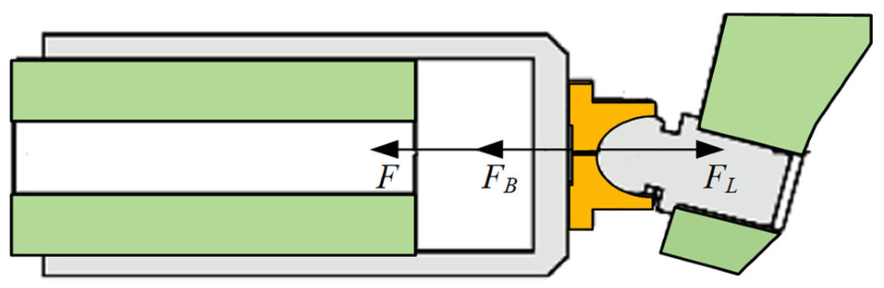
When the control flow,
Qc, enters and exits the control piston chamber, the control piston rod will extend or retract, and its kinetic analysis is shown in
Figure 2, which mainly takes into account the reaction force,
F, from the swash plate; the hydraulic pressure,
FL, formed by the oil in the piston chamber; and the viscous resistance,
FB, in the process of movement.
The force balance equation is:
where
mp is the mass of the control piston, kg;
Bp is the viscous damping coefficient of the control piston, N·s/m; and
is the reaction force of the swash plate on the piston rod, N.
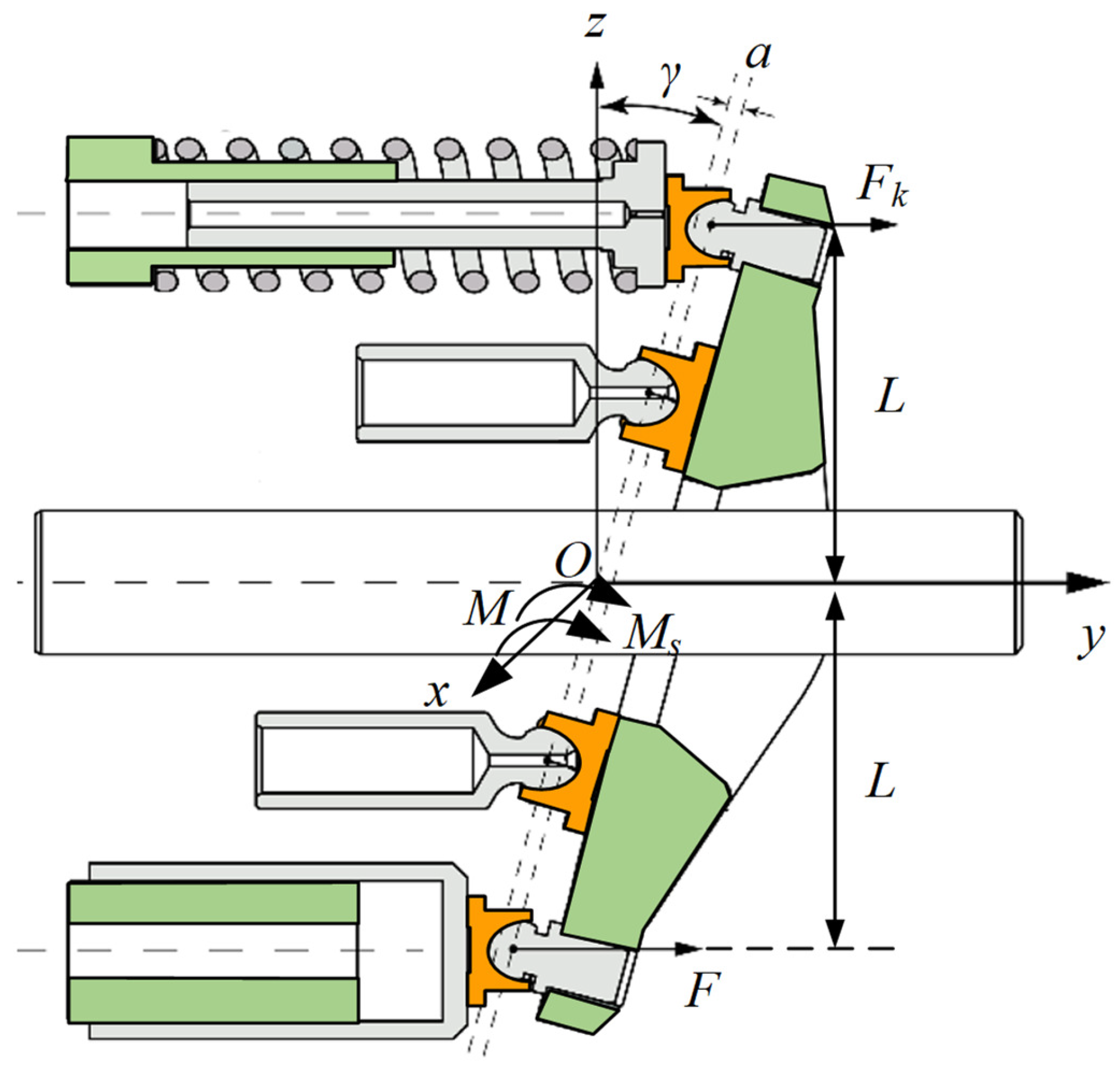
The control piston rod pushes the swash plate to rotate, so that its inclination changes to adjust the pump displacement. The swash plate’s kinetic analysis is shown in
Figure 3. This paper focuses on the dynamic change in swash plate inclination, so only the moment around the swash plate rotary axis,
Ox, is analyzed. This paper stipulates that the moment that the swash plate inclination increases is positive. The torque that rotates the swash plate around the axis
Ox includes the control torque,
Mc, formed by the driving force
F of the control piston, the offset torque
Mk formed by the offset spring force
Fk, the swash plate’s own inertial torque
Ms, and the combined torque of the other forces on the swash plate,
M. The control torque,
Mc, of the control piston and the offset torque,
Mk, of the offset spring are called the load torque of the variable displacement mechanism.
The moment balance equation for the swash plate around the Ox axis is as follows:
where
L is the vertical distance from the control piston and offset spring force to the swash plate rotary axis, m;
Is is the rotational inertia of the swash plate assembly around the swash plate rotary axis, kg·m
2;
γ is the swash plate inclination, rad;
K is the stiffness of the offset spring, N/m; and
x0 is the pre-compression of the offset spring, m.
Equations (7) and (8) can be linked to obtain the control piston–swash plate integrated dynamic equations:
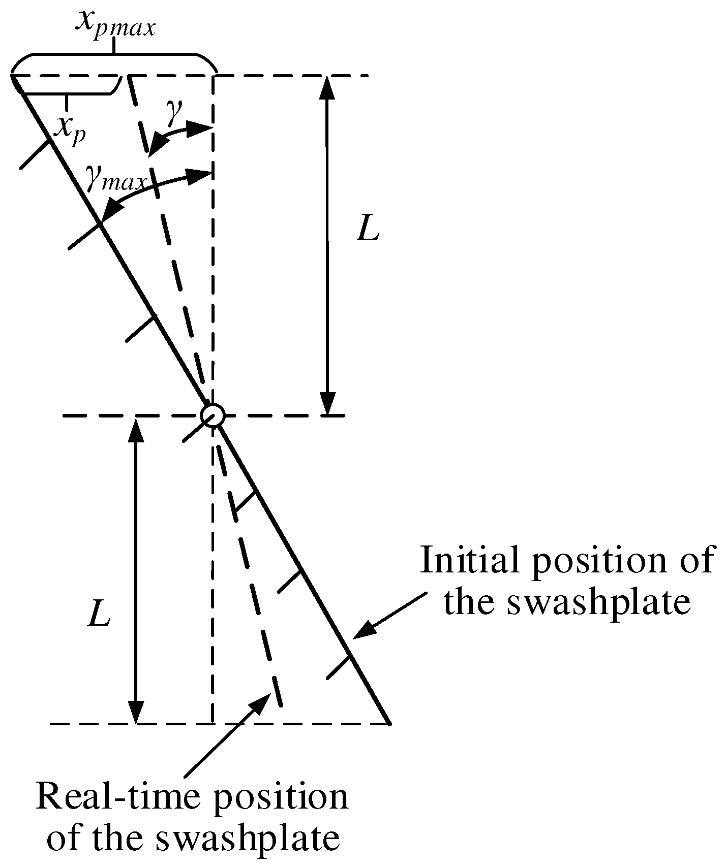
As the swash plate and control piston are mechanically connected, a natural geometrical relationship exists between the swash plate inclination,
γ, and the control piston displacement,
xp, as shown in
Figure 4.
The geometric relationship can be derived from
Figure 4:
Since the swash plate always moves within a slight angle, it can be approximated that
, then there is:
By substituting Equation (11) into Equations (6) and (9) and collating them, we obtain:
where
is the combined mass of the control piston and swash plate assembly, kg.
In addition, the modulus of elasticity of the pump’s solid material is much larger than that of fluid. Therefore, the model in this paper considers the solids in contact with the oil to be rigid, so the vibrations and associated effects are not considered.
2.4. Detailed Analysis of Swash Plate Torque
When the rotational speed is constant, the flow and pressure control of the servo pump are achieved by changing the swash plate inclination to adjust the displacement. Therefore, it is necessary to conduct a detailed study of several key moments on the swash plate, as the various moments on the swash plate directly affect its dynamic response, which in turn affects the flow and pressure regulation. As stated previously, the swash plate is rotated around the Ox axis by the load moment of the regulating mechanism, the moment of the swash plate inertia, and the combined moment of other forces on the swash plate, M. The load moment of the regulating mechanism and the moment of the swash plate inertia have already been calculated in the previous section. This section will provide a detailed analysis of the combined moment of other forces on the swash plate, M. The combined moment comprises the hydraulic moment Mp, which is formed on the swash plate by the oil pressure in each plunger chamber, the moment of inertia M1, which is formed on the swash plate during the movement of each plunger, the friction moment M2, which the swash plate experiences when it rotates, the friction moment M3 between the plunger ball and the ball groove of the sliding shoe, and the self-weight moment M4 generated by the swash plate’s own weight.
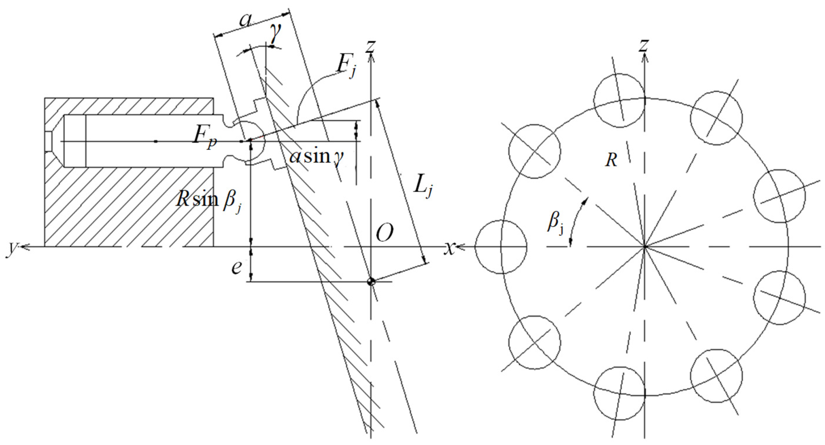
2.4.1. Hydraulic Torque of the Plunger Chamber on the Swash Plate
As the cylinder block rotates, the plunger chamber switches between the pump’s low-pressure inlet and high-pressure outlet connection, causing the oil pressure to alternate between high and low. An alternating hydraulic moment is created on the swash plate at a frequency equal to the piston pump’s pressure pulsation frequency. Due to the high rotational speed and the high discharge pressure of the pump, hydraulic torque has a significant value and high-frequency change, which has an essential influence on the dynamic characteristics of the swash plate.
Figure 5 analyzes the hydraulic moment of a single plunger on the swash plate, while the combined hydraulic moment of all plungers in one cycle is
MP. This paper specifies that a positive hydraulic moment causes an increase in the swash plate inclination, while a negative hydraulic moment causes a decrease.
Based on the dynamic analysis presented in
Figure 5, it can be inferred that:
where
Fj is the hydraulic pressure of the
j-th plunger on the swash plate, N,
;
Fp is the hydraulic pressure on the plunger, N;
Pj is the hydraulic pressure in the
j-th plunger chamber, Pa;
A is the area of the plunger, m
2;
Lj is the length of the arm from
Fj to the swash plate rotating shaft, m;
R is the radius of the plunger distribution circle, m;
βj is the circumference distribution position of the
j-th plunger,
, rad;
is the cylinder block angle, rad;
,
,
ω is the rotation angular speed of the cylinder block, rad/s;
a is the offset distance between the force point of the plunger ball head and the rotating shaft of the swash plate, m; and
e is the eccentricity of the swash plate, m.
This paper stipulates that
a is positive when the swash plate rotor axis is located to the right of the force point of the plunger ball head, and negative when the opposite is true;
e is positive when the rotor axis is moving in the direction of the upper dead center of the plunger movement (the plunger is fully extended), and negative when the opposite is true. The combined hydraulic torque of each plunger on the swash plate is:
During one cylinder block rotation cycle, the valve plate’s structure affects the variation in the oil pressure,
Pj, of each plunger chamber. This paper focuses on the asymmetric valve plate with a triangular vibration damping groove, whose structure and the corresponding plunger chamber pressure are shown in
Figure 6.
When the pump cylinder rotates one revolution, each plunger will pass through a high-pressure zone, a low-pressure zone, and two transition zones formed by the triangular damping groove.
In the transition zone, the pressure in the plunger chamber undergoes a nonlinear change, and its specific derivation process is more complicated. Usually, the effective method is to linearly approximate the plunger chamber pressure in the transition zone. This allows for obtaining a formula for the change in the plunger chamber pressure during the rotation period.
where Δ
β is the central angle corresponding to the pump triangular vibration damping groove, rad.
2.4.2. Inertia Torque of the Plunger on the Swash Plate
When the cylinder block rotates, the plunger moves in a reciprocating straight line relative to the block and rotates around the main shaft. The movement trajectory of the plunger ball head on the swash plate is an ellipse, as shown in
Figure 7. When the plunger rotates at an angle of
β around the central shaft from the top dead center position
A to position
B, the plunger ball head moves along an elliptical arc,
AB. The projection of this arc on the surface,
Oxy, is an arc,
AB′. Based on the geometric relationship, the axial displacement of the plunger can be determined as follows:
During the process of changing the swash plate inclination and cylinder block rotation, the speed and acceleration of the
j-th plunger’s axial motion are:
where
vj represents the axial motion speed of the
j-th plunger, m/s;
aj represents the axial motion acceleration of the
j-th plunger, m/s
2.
Then, the combined inertia moment of each plunger on the swash plate is:
Equation (19) shows that the combined inertia moment of each plunger to the swash plate changes periodically. However, since the mass of the plunger is usually small, the combined moment amplitude is also tiny.
2.4.3. Frictional Torque of Swash Plate Rotation
The swash plate is fixed to the piston pump housing by two bearings, and when the swash plate rotates, it is subjected to frictional resistance torque from the bearings. This torque is affected by the pressure of the pump inlet and discharge chambers. The average value of this resistance can be expressed as:
where
r1 is the radius of the swash plate support axis, m;
f1 is the bearing friction coefficient at the swash plate support. Since
r1 and
f1 are usually small, the frictional torque
M2 value is small.
2.4.4. Frictional Torque between the Plunger Ball Head and the Boot Ball Groove
When the swash plate rotates, the plunger ball head and the shoe ball groove slide relative to each other, resulting in frictional torque. This torque is also affected by the pressure of the pump inlet and discharge chamber, and can be expressed as an average value:
where
r2 is the radius of the plunger ball head, m;
f2 is the friction coefficient between the plunger ball head and the boot ball groove. Similar to
M2, because
r2 and
f2 are usually small, the value of frictional torque
M3 is small.
2.4.5. Self-Weight Torque
When the swash plate’s gravity center does not fall on the rotating axis of the swash plate, the gravity of the swash plate will produce a self-weight torque, the magnitude of which is:
where
G is the weight of the swash plate, N;
b is the distance between the swash plate’s gravity center and the rotating axis, m. Because
b is usually tiny, the self-weight torque,
M4, of the swash plate is small.
2.5. Piston Pump Output Characteristic Model
The pump outlet flow continuity equation is as follows:
where
Qp is the load flow rate of the pump, m
3/s;
kQ is the flow coefficient,
, m
3/s;
n is the spindle speed, r/min;
d is the diameter of the plunger, m;
Dp is the diameter of the plunger distribution circle, m; Z is the number of plungers;
Cp is the leakage coefficient in the pump, m
3/(Pa·s);
Pp is pump outlet pressure, Pa; and
Vp is the pump outlet volume, m
3.
Rewrite Equation (23) as:
By taking state variables
and combining Equations (5), (12), (13) and (24), the state space equation of the SAIP system can be obtained as follows:
where
,
,
,
is the other torque M, subjected to the swash plate mentioned above,
. To facilitate writing in the derivation process,
and
are abbreviated as
and M, respectively, in the rest of the paper.
Since the modulus of elasticity of the oil, pump leakage coefficient, etc., are affected by factors such as air content and temperature in the fluid, which are time-varying parameters, and then combined with Equation (25), it can be seen that the SAIP system is a fourth-order nonlinear time-varying system.
3. Simulation Study of SAIP’s Output Characteristics
In this section, the SAIP simulation model is developed in Simulink, and the output characteristics and the influencing factors are explored in the simulation. The output characteristics of the SAIP refer to the dynamic characteristics of the pump outlet pressure and output flow rate.
In the simulation model, the load is simulated with a throttled hole, and the magnitude of the load is changed by changing the diameter of the hole, and its flow–pressure equation is:
where
Cd is the throttling coefficient;
df is the hole’s diameter, m.
The SAIP model established in Simulink consists of four parts: the electro-hydraulic servo valve input voltage part, the load part, the servo pump body part, and the servo pump status display part. When the control voltage is positive, the high-pressure fluid enters the control piston cavity through the servo valve, so that the control piston rod pushes the swash plate inclination to reduce; when it is negative, the high-pressure fluid in the control piston cavity returns to the oil tank through the servo valve, and the swash plate inclination increases under the action of other swash plate moments (mainly for the combination of hydraulic torque and offset spring torque), and pushes the control piston rod to retract at the same time. The parameters used in the simulation are shown in
Table 1. The solver set in Simulink is the Bogacki–Shampine solver, which computes the state of the model as an explicit function of the current value of the state and the state derivatives, which belongs to the fixed-step solver. The step size is set to 0.0001 s.
3.1. Effect of Offset Spring’s Stiffness on Output Characteristics
The function of the offset spring is to control the swash plate at maximum inclination in the initial state of the pump, allowing for maximum flow output. Additionally, it provides part of the return torque during the swash plate rotation process. If the offset spring’s stiffness is too tiny, the swash plate may return weakly or even jam, resulting in no flow output from the pump and potentially causing severe accidents. Conversely, if the stiffness is too great, the swash plate may not be easily driven by the variable displacement mechanism, resulting in a slow displacement adjustment and reduced performance. Therefore, it is necessary to investigate the impact of the offset spring’s stiffness on the SAIP’s output characteristics.
The offset spring’s stiffness of the SAIP mentioned above was 17.8 kN/m. For the sake of obvious comparison, the offset spring’s stiffness values of the control group were taken to be 1.78 kN/m and 178 kN/m. The swash plate initial inclination was set to 0°, and the electro-hydraulic servo valve input voltage was −4 V (because the larger reverse voltage makes the control piston chamber return oil smoothly: this excludes the effect of the servo valve on the swash plate dynamics and highlights the role of the offset spring). The dynamic characteristics of the swash plate and the output characteristics of the SAIP during the rotation of the swash plate to the maximum inclination angle were explored through a simulation, and the results are shown in
Figure 8 and
Figure 9.
Figure 8 indicates that increasing the offset spring’s stiffness from 1.78 kN/m to 17.8 kN/m reduces the swash plate’s return time from minimum to maximum inclination by half. However, there is no significant reduction in the return time when the stiffness is increased from 17.8 kN/m to 178 kN/m. Increasing the stiffness in the small stiffness stage improves the return speed. However, the effect is no longer significant after a certain point. Additionally, excessively high stiffness increases the volume, weight, and the load of the variable displacement mechanism, leading to a slow displacement adjustment. The conclusion drawn from the analysis can be used to determine the offset spring’s stiffness for the piston pump design.
It can be seen from
Figure 9 that the change rule of pressure and flow rates is basically the same as the change rule of swash plate inclination with different spring stiffness. The only notable difference is that the swash plate inclination increases in the first 0.05 s while the pressure and flow rates remain at 0. The reason is that the oil output from the pump needs to fill the pipe and flow out of the throttle orifice before the pressure can be established. This process takes a certain amount of time, resulting in zero pressure and flow rate for the first 0.05 s.
3.2. Effect of Control Piston’s Diameter on Output Characteristics
The control piston’s role is to push the swash plate to reduce its inclination. When the oil pressure in the control piston chamber is constant, the force of the control piston rod acting on the swash plate is determined by the control piston’s cross-sectional area, so the control piston’s diameter will affect the dynamics of the swash plate inclination, and then affect the output characteristics of the SAIP.
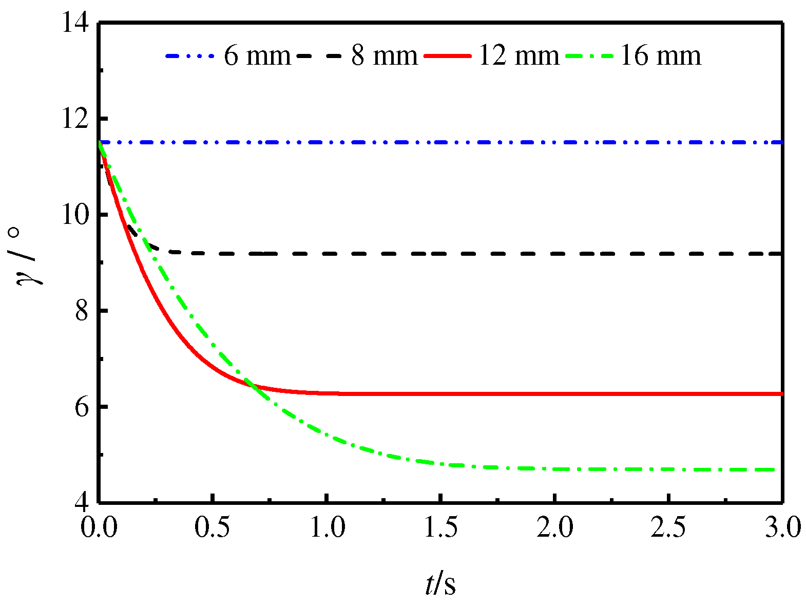
The study simulated the output characteristics of a SAIP with a control piston diameter of 12 mm and compared it to control groups with control piston diameters of 6 mm, 8 mm, and 16 mm. The initial inclination was set to 11.5°, and the servo valve input voltage was 1 V. The output characteristics in reducing the swash plate inclination driven by the control piston rod were explored. The results are presented in
Figure 10 and
Figure 11.
Figure 10 demonstrates that when the control piston’s diameter is 6 mm, the control piston rod cannot push the swash plate. As the diameter increases to 8 mm and 12 mm, the speed of swash plate inclination reduction also increases. However, when the control piston’s diameter is 16 mm, the speed of the swash plate inclination reduction is lower than that of 8 mm and 12 mm. This is because, when the piston diameter is increased, the chamber volume also increases, requiring more oil to enter. The opening of the servo valve restricts the speed of oil entering, resulting in a lower rate of swash plate inclination when the control piston’s diameter is 16 mm. It is evident that the variable displacement mechanism cannot push the swash plate when the diameter is too small. Increasing the diameter can improve the variable displacement mechanism’s action speed, but it can reduce the speed if it is too large. This conclusion can guide the determination of the control piston’s diameter in the SAIP design.
It should be pointed out that the SAIP studied in this paper is a self-supplied pump. That is, the oil source of the servo valve is the pump outlet oil. When the load is constant, the swash plate inclination decreases, causing the pump displacement and outlet oil pressure to decrease. Eventually, the variable displacement mechanism will not push the swash plate, and it will stabilize at a certain angle. This is a significant characteristic of the self-supplied servo pump. Therefore, in
Figure 10, the swash plate is stabilized at a certain angle. The larger the control piston’s diameter, the greater the force of the control piston rod on the swash plate. As a result, the swash plate is stabilized at a smaller angle.
The analysis of
Figure 11 shows that the change rule of pressure and flow rates is basically the same as the change rule of inclination with different control piston diameters. However, since the SAIP is self-supplied, there is no high-pressure oil in the control piston chamber before starting, and the displacement adjustment begins almost until the pump has wholly established the pressure.
Figure 11 shows that the process of increasing pressure takes about 0.02 s.
3.3. Effect of Rotation Speed on Output Characteristics
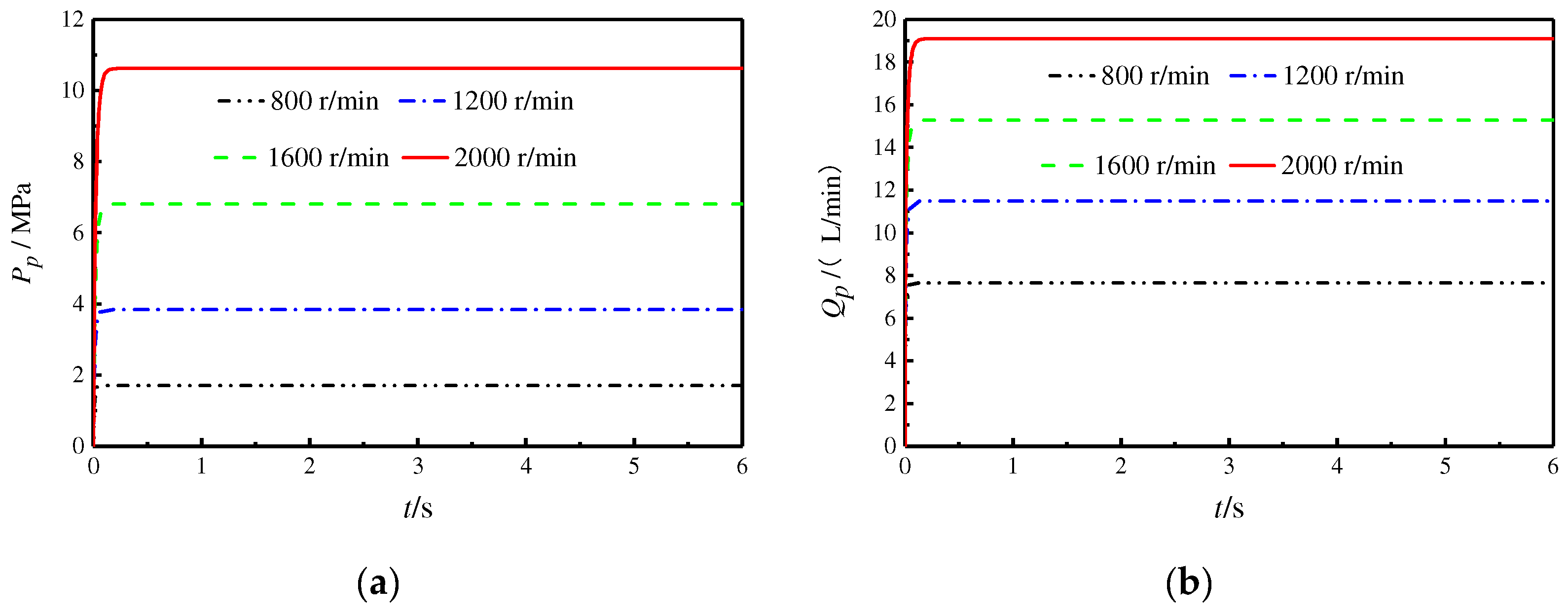
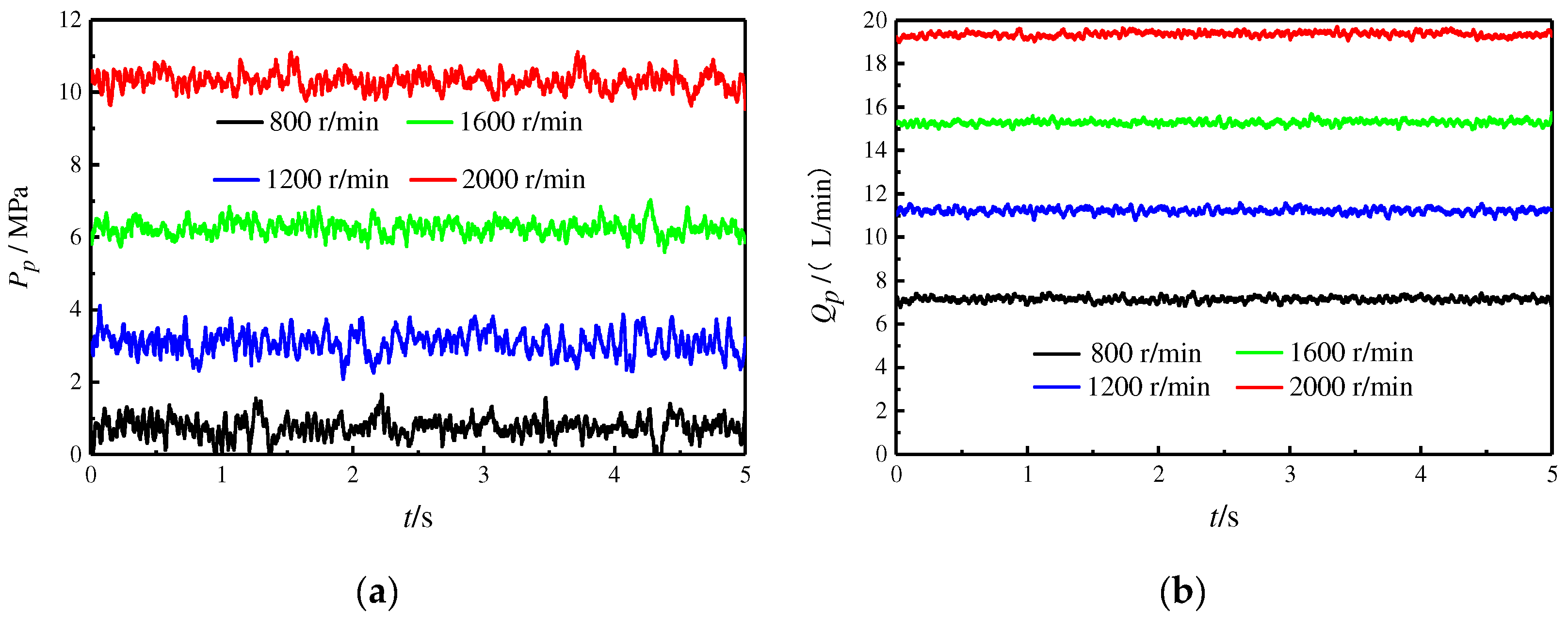
To study the effect of rotation speed on the output characteristics of the SAIP, the servo valve voltage is taken to be 0 V, and the rotational speeds are taken to be 800 r/min, 1200 r/min, 1600 r/min, and 2000 r/min for the simulation. The other parameters are shown in
Table 1, and the simulation results are shown in
Figure 12.
Figure 12 shows that the higher the rotation speed, the higher the output flow and the higher the pressure formed. However, the flow rate and speed are not strictly proportional. As can be seen from the figure, the steady-state flow rate is 7.8 L/min at 800 r/min and 19 L/min at 2000 r/min. The magnitude of the flow rate increase did not change to 2.5 times the initial magnitude as well as the rotational speed. The main reason is that the system pressure increases, and the leakage in the pump increases, resulting in a lower output flow. The results show that the pump’s flow rate is not strictly proportional to the displacement, and the higher the load, the smaller the pump’s output flow at the same speed.
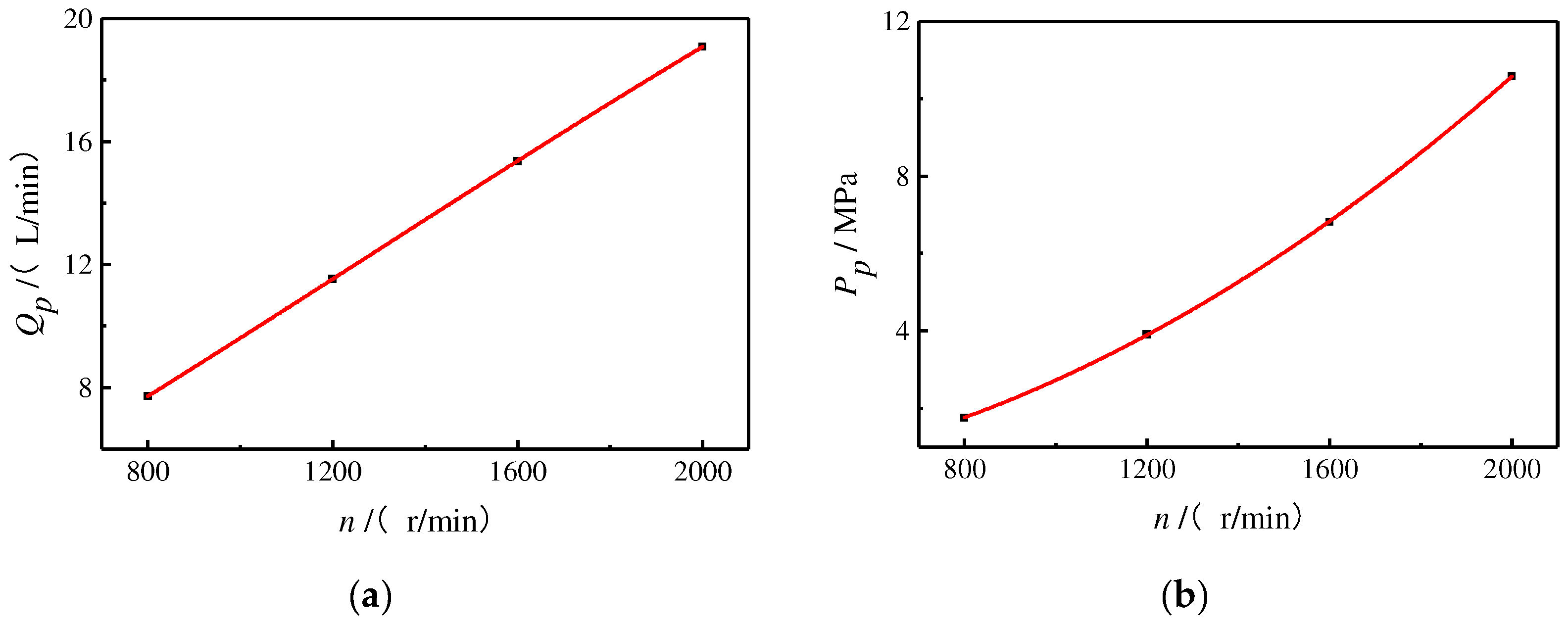
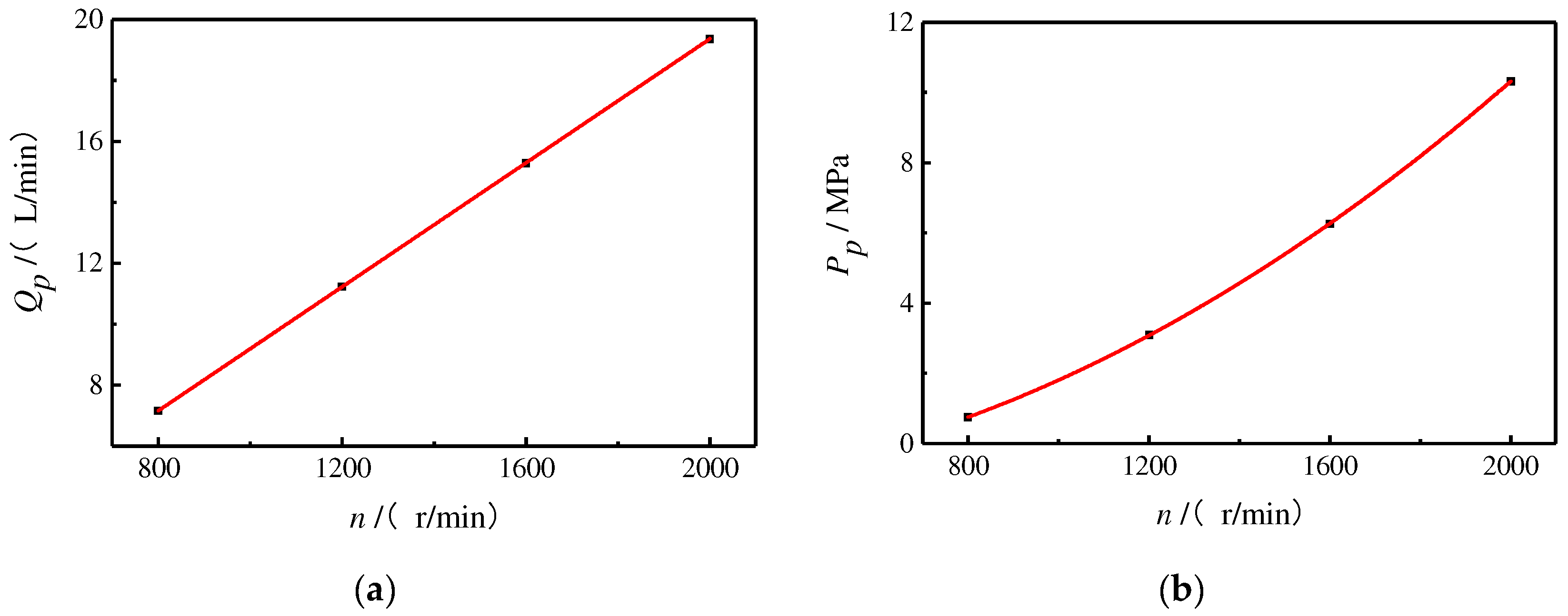
In order to visually show the influence of rotational speed on the flow rate and pressure, the steady-state average values of the flow rate and pressure at different speeds were calculated, and the fitting curves of the flow rate and pressure with speed were drawn according to the results, as shown in
Figure 13.
As can be seen in
Figure 13a, the flow rate is almost proportional to the speed, and it can be seen in
Figure 13b that under the condition of a certain load, the pressure at the outlet of the servo pump has an obvious nonlinear relationship with the speed, and the relationship curve is convex. With the increase in the rotational speed, the rate of change in pressure also increases gradually, that is, under the same rotational speed increase, the higher the rotational speed, the greater the increase in pressure. This law is also consistent with the pressure–flow equation of the throttling holes.
3.4. Effect of Servo Valve’s Input Voltage on Output Characteristics
To investigate the effect of the servo valve’s input voltage on the output characteristics of the SAIP, this section simulates the two processes of decreasing and increasing the swash plate inclination.
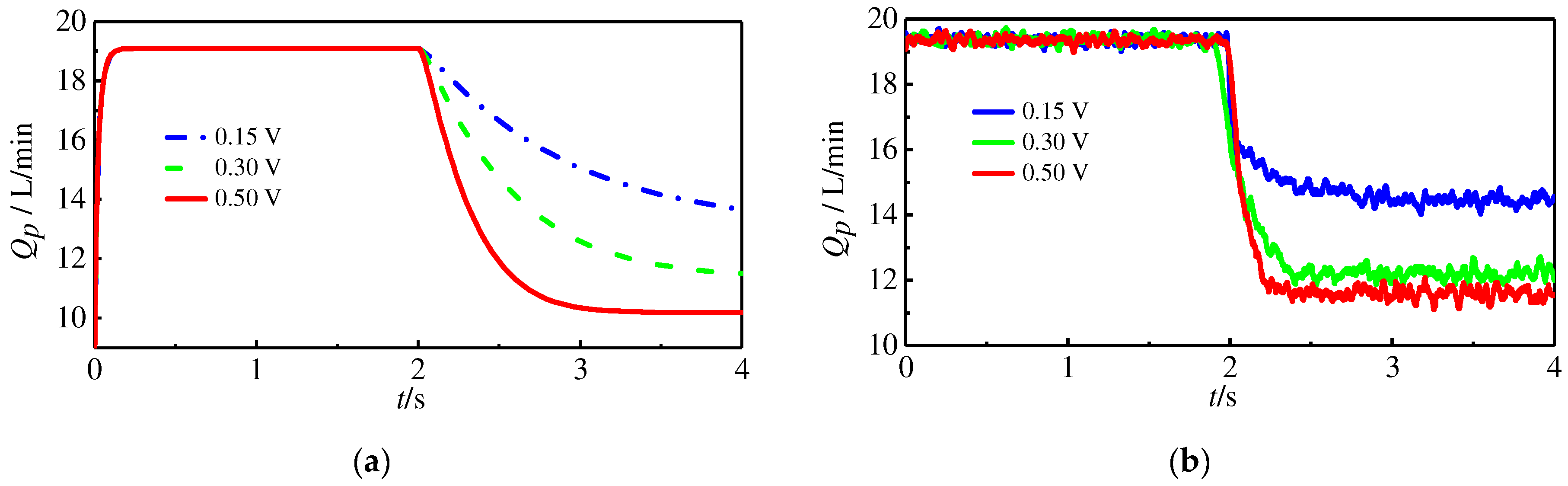
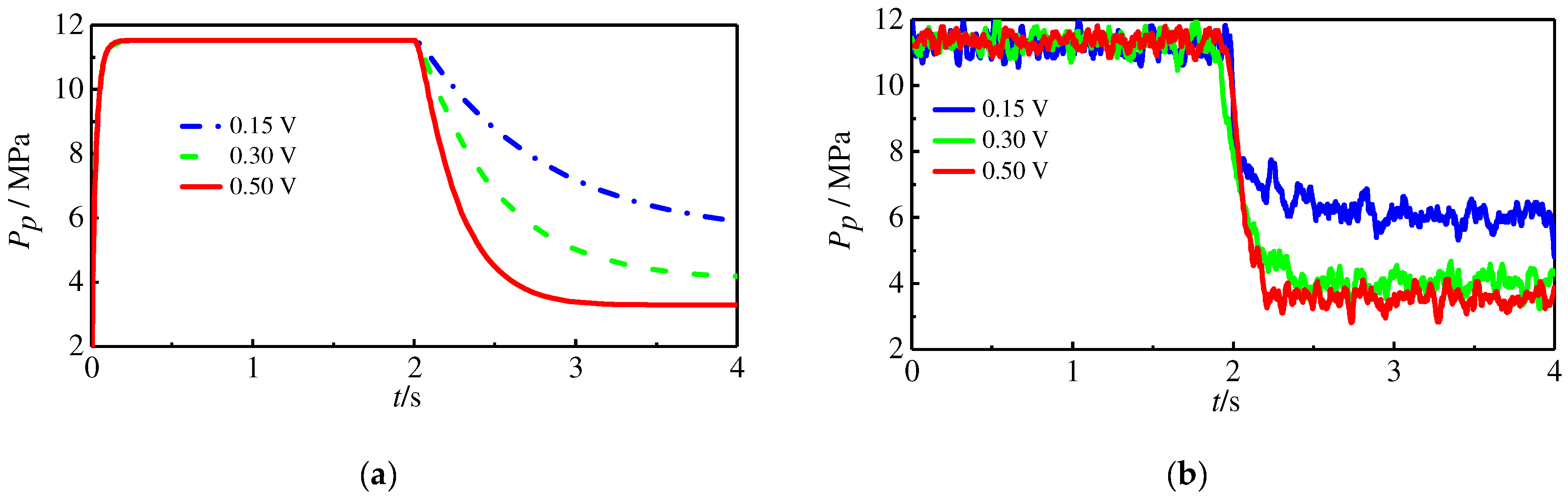
3.4.1. The Process of Decreasing the Swash Plate Inclination
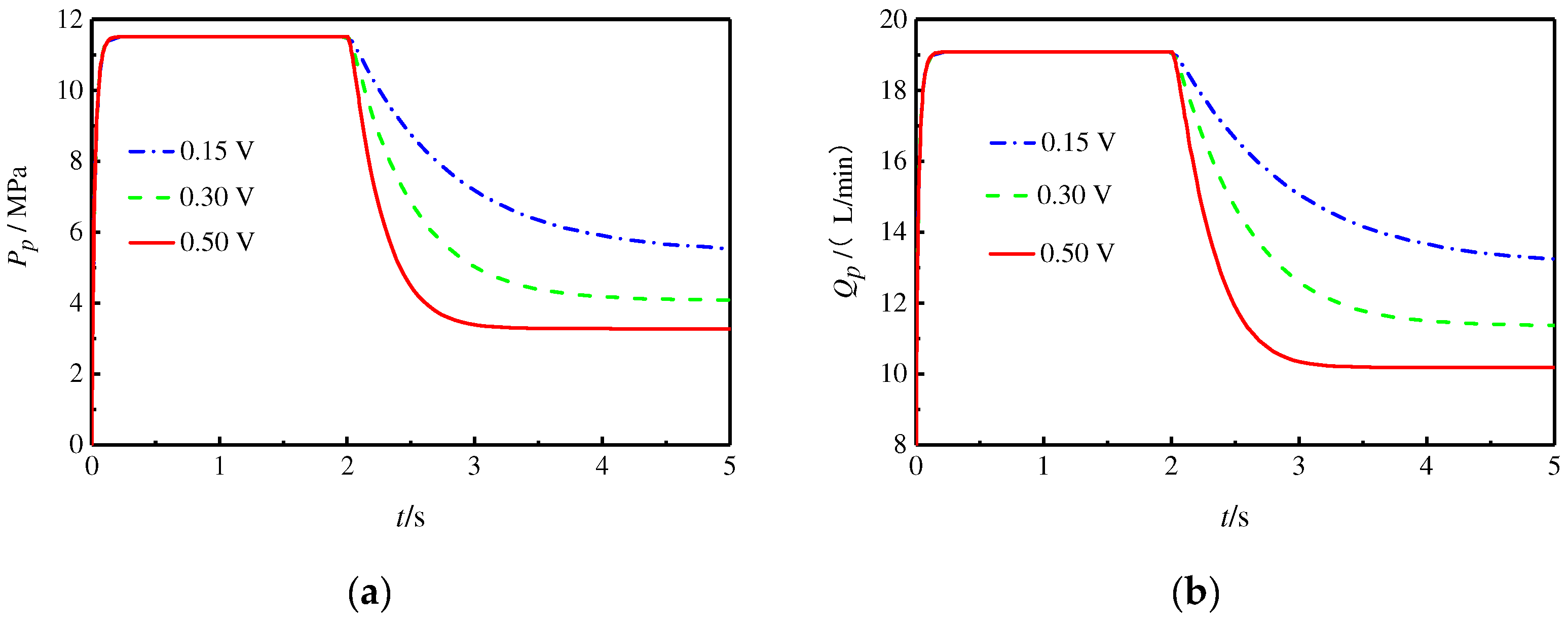
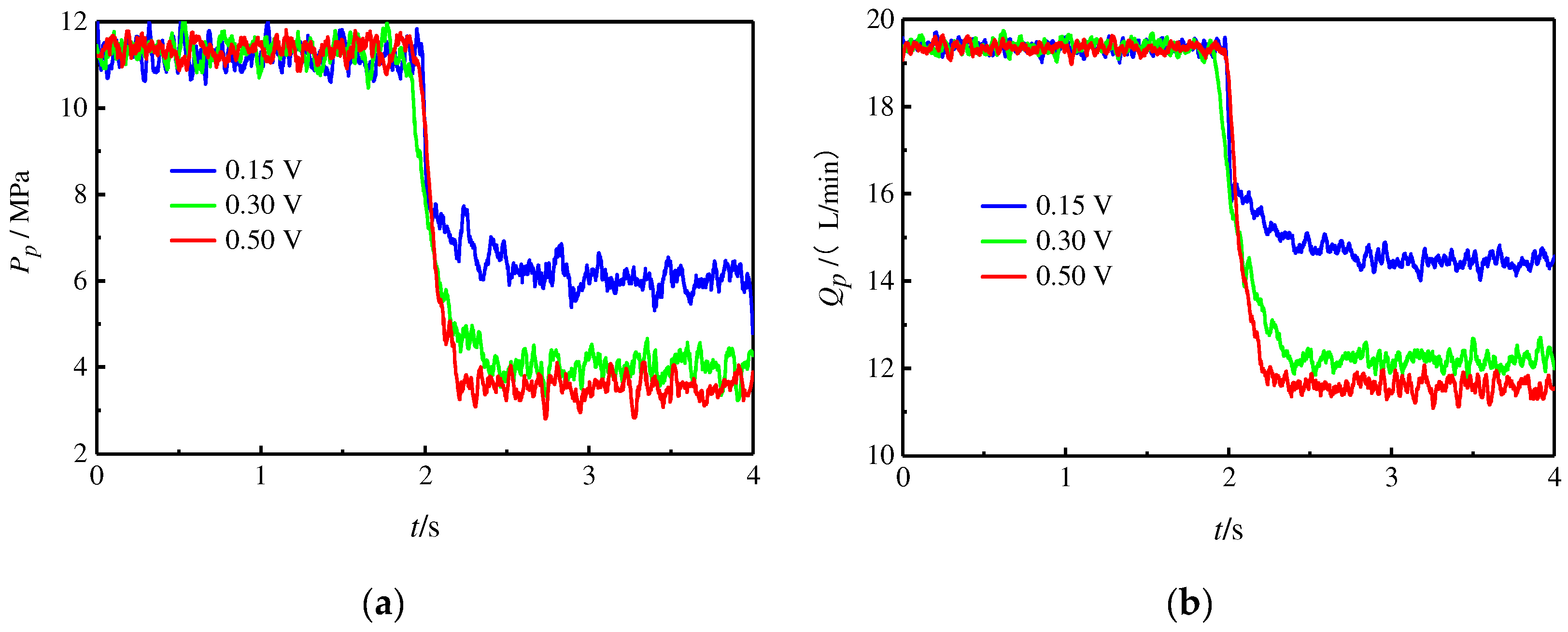
The servo valve’s input voltages were taken as 0.15 V, 0.3 V, and 0.5 V, the initial swash plate inclination was set to 11.5°, other parameters are shown in
Table 1, and the simulation results are shown in
Figure 14.
Figure 14 shows that as the voltage increases, the change in displacement accelerates significantly. However, because of the self-supplied characteristics, as seen in the previous section, the swash plate inclination will be stabilized at a specific value, so the pump outlet pressure and output flow rate will also be stabilized to a particular value. At a steady state, although oil is still flowing into the control piston chamber, while the control piston chamber has leakages, the inflow of oil just compensates for the oil leakage, so the control piston no longer moves. The voltage increases, the servo valve opening increases, the throttling effect on the oil decreases, and the final oil pressure of the control piston chamber can be higher, which can make the swash plate stable at a smaller angle, so the pump outlet pressure and output flow can also be stable at a smaller value.
3.4.2. The Process of Increasing the Swash Plate Inclination
The servo valve voltage was set to 0 V for the first 0.6 s, 4 V for 0.6~1 s, and −0.15 V, −0.3 V, and −0.5 V after 1 s. The purpose of this setting is to wait for the SAIP to establish the outlet pressure fully, then adjust the swash plate to the smallest angle that can be achieved, and then let the swash plate return to the position to explore the pressure and flow dynamics of the SAIP with different reverse voltages. The results are shown in
Figure 15.
Figure 15 shows that as the voltage increases in the reverse direction, the outlet pressure and output flow rate to return to the maximum time value continue to shorten. The reason is that the voltage increases, the servo valve opening increases, the throttling effect of the oil in the control piston chamber is weakened, the oil is more accessible to return to the tank, and the swash plate is more straightforward to return to the position. A comparison with the simulation results of controlling the swash plate inclination to decrease shows that for the same voltage, the time required for the swash plate to return to the maximum value is shorter, about half the time needed for the former.


