Abstract
With advances in minimally invasive ophthalmic surgery (MIOS), novel vitreoretinal surgeries have been proposed to treat retinal diseases. Due to the limitations of manual techniques, surgical robots have been introduced for such surgeries. Among ophthalmic surgical robots, the remote center of motion (RCM) mechanism is widely used due to its unique advantages. In this paper, a novel RCM is proposed. Based on the configuration, the kinematics and singularity are analyzed. Subsequently, the planar workspace is analyzed based on ocular anatomy and the requirements of MIOS. The optimal configuration is selected according to the workspace coverage analysis, and the three-dimensional workspace is obtained. Finally, a prototype is built, and the motion is validated. When compared with the related prior RCM mechanisms, the resulting design has qualified workspace coverage, more concise kinematics, and reduced motion coupling with all actuators placed at the distal end of the base. The proposed RCM mechanism is suitable for common MIOS. Future research will further optimize the mechanical structure and control algorithm to improve the accuracy of the prototype.
1. Introduction
With advances in minimally invasive ophthalmic surgery (MIOS), novel vitreoretinal surgeries have been proposed to treat retinal diseases such as macular degeneration. Since conventional manual techniques cannot meet the precision requirement within the eye [1,2], surgical robots have been introduced to overcome this limitation.
During MIOS, surgical instruments are inserted into the eye through a scleral incision, and various operations are performed through and about this incision throughout the procedure. As shown in Figure 1, since the diameter of the scleral incision is extremely small, it can be considered to be a point; thus, the motions of the surgical instruments can be described as pan–tilt–spin rotations (or roll–pitch–yaw motions in kinematics) centered at the incision point and an axial translation for the insertion and retraction [3]. A remote center of motion (RCM) mechanism is proposed in response to the above characteristics of MIOS. The RCM mechanism restricts the movement of the ends of surgical instruments around a fixed point where no physical structure exists. Robots based on the RCM mechanism are considered more suitable for MIOS than conventional muti-joint robots, as they generate RCM points using mechanical structures and thus have reduced degrees of freedom (DOF) and decoupled motion [4].
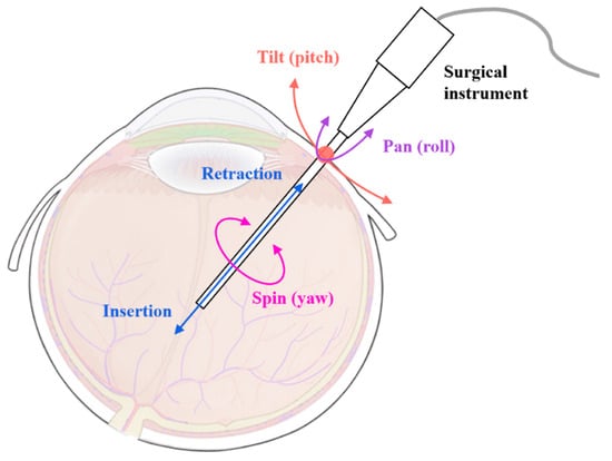
Figure 1.
The motions of the surgical instrument during MIOS.
The common RCM mechanism can be formed by structures such as circular tracking arcs, parallelograms, belts, spherical linkages, gear trains [3,4,5,6,7], etc. Among the broad variety of RCM mechanisms, parallelogram-based RCM mechanisms are a notable subgroup [8]. Proposed and further developed by Taylor et al. [9,10], the parallelogram-based mechanism has been widely applied to ophthalmic surgical robots [11,12,13].
For parallelogram RCM mechanisms applied to surgical robots, the manipulator generally has three or four DOF, including two rotations (2R) and one translation (1T), or 3R1T. The type synthesis of the parallelogram RCM mechanism has been systematically presented [14,15]. In the earlier proposed parallelograms, the translational DOF was often achieved by installing linear actuators directly at the manipulators, which is not suitable for MIOS. Typically, it is more appropriate to mount the linear actuator at a base that is far away from the manipulator, as mounting actuators near the surgical instruments adds to the mass of the manipulator, resulting in a significant increase in the load on the rotating actuators. In addition, the excessive end volume may interfere with the imaging equipment and compress the operating space [16,17].
In recent studies, a number of parallelogram RCM mechanisms with linear actuators mounted closer to the base have been proposed. Lin et al. proposed a parallelogram with passive limbs and thus obtained a 2R1T RCM controlled by the actuators mounted on the base [17]. Zhang et al. introduced extra parallel linkages to the conventional parallelogram mechanism, thus converting the rotational motion at the base to translational motion of the manipulator [18]. Similarly, Gijbels et al. also increased the number of parallelograms and designed a 2R1T parallelogram mechanism that introduces translation joints near the base and is simpler to control [19]. The mechanism has been adopted by surgical robots which were later used in animal studies [20], as well as in clinical studies of human vitreoretinal surgery [21]. A methodology was later proposed for the mechanism above to analyze its configurations and optimize the workspace [16].
In addition to the improvement of the parallelogram mechanism itself, another approach is to introduce a linear motion mechanism. Inspired by the Peaucellier–Lipkin straight-line linkage, Chen et al. proposed a methodology to generate RCM by combining two symmetric virtual central mechanisms and designed a 1R1T RCM mechanism based on it [22]. Ye et al. introduced a linear motion mechanism at the end of the parallelogram mechanism and proposed a planar 1R1T RCM mechanism, which has a large singularity-free motion space [23].
The mechanisms described above can be seen as modifications to the conventional parallelogram RCM mechanism, which allow the translational actuator to be mounted at the base while retaining the stability of the parallelogram mechanism. However, the translational DOF in these mechanisms are generally achieved by more than one rotational actuator, and this coupled translational motion can make it more difficult to control [24]. Furthermore, in the planar 1R1T parallelogram RCM mechanism, the load of the rotating motor is relatively large; thus, a gearbox or other additional mechanisms are needed to amplify the torque [25,26], which increases the overall complexity and volume. These problems have resulted in most of the novel parallelogram RCM mechanisms remaining in the research stage, and it is difficult to apply them in surgical robots.
To avoid the inherent deficiencies of the parallelogram mechanism, other types of novel RCM mechanisms have been proposed. Liu et al. proposed an RCM mechanism based on dual-triangular linkage [24]. He et al. designed a novel type synthesis method based on the coupled motion of two DOF to obtain new virtual center of motion (VCM) mechanisms, and a series of RCM mechanisms were obtained by combining different configurations of VCM mechanisms [27]. Additionally, as an alternative to the conventional drive method, cable transmission is also an effective solution capable of realizing the translational DOF with actuators mounted on the base [28,29].
In addition to the improvement of the planar mechanism, some three-dimensional RCM mechanisms have been proposed. Wang et al. combined a parallelogram mechanism with a 3-UU parallel mechanism and proposed an RCM mechanism with two rotational DOF [30]. Chen et al. combined two planar mechanisms and proposed a novel spatial RCM with three rotational DOF and one translational DOF [31]. In this mechanism, the rotational and translational motion of the end-effector is achieved by a virtual screw with a cable-driven mechanism so that the actuator can be mounted at the base; however, this results in coupled motion.
For the previously described RCM mechanisms that enable all the actuators to be mounted at the base, their translational motion is usually achieved by more than one actuator, which leads to coupled motion and introduces slight controlling errors that cannot be neglected in MIOS. In addition, some mechanisms that do not use parallelograms, while being able to achieve effective RCM, can lead to design complexity and lower stability.
Based on the considerations above, this paper proposes a novel 2R1T RCM mechanism composed of two planar parallelograms, which has less motion coupling with all the actuators mounted on the base. The remainder of the paper is organized as follows: Section 2 presents the configuration design with analysis of its kinematics and singularities. Then, the workspace is analyzed in Section 3, and the optimal parameters are settled based on the analysis, and the three-dimensional workspace is sketched. Based on the efforts above, a prototype is built and the motion is validated in Section 4. Finally, the conclusions are drawn in Section 5.
2. Preliminary Design of the 2R1T RCM Mechanism
2.1. Concept of the Spatial 2R1T RCM Mechanism
As shown in Figure 2, the proposed spatial RCM mechanism consists of two different planar parallelogram mechanisms, and the working planes of both mechanisms can perform rotation with the control of the rotational joints (R-joint) mounted at the base. In this mechanism, the rotation within the plane of each planar mechanism is passive and driven by the rotating joint of the other mechanism.
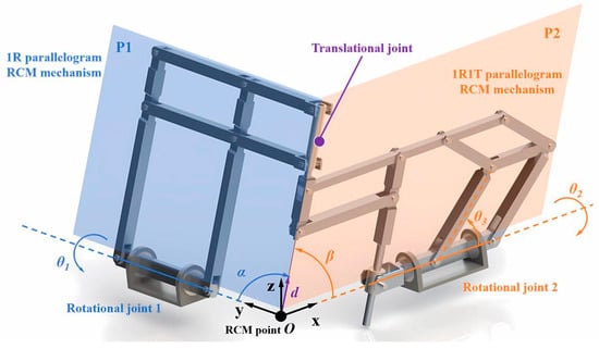
Figure 2.
Schematic of the proposed 2R1T RCM mechanism.
In each planar mechanism, all R-joints, except the rotational joint on the base, are normal to the same plane, which is denoted by P1 or P2 in Figure 2. In addition, in each planar mechanism, both the axes of the R-joint on the base and the end manipulator also lie in the plane. Thus, each parallelogram mechanism is confined in a plane whose normal state is determined by the rotation of the R-joint on the base.
A 1R1T RCM mechanism and a 1R RCM mechanism are used to synthesize the required spatial mechanism. Apparently, when the respective RCM points of the two planar mechanisms intersect at point O in Figure 2, the translational and rotational motions of the end-effector always pass through O, so the synthesized spatial mechanism forms a functional RCM at this point. Moreover, when P1 and P2 are perpendicular to each other and the end limbs of the two mechanisms are connected by a translational joint so that they are co-linear to a common axis, which intersects the axes of the two R-joints on the base at the RCM point O, the rotational motions in the two planes are orthogonal. Therefore, the proposed spatial RCM mechanism has a 2R1T mobility.
2.2. Type Synthesis of the Spatial 2R1T RCM Mechanism
As indicated above, the proposed 2R1T mechanism is synthesized from two planar mechanisms, respectively: a 1R parallelogram mechanism and a 1R1T parallelogram mechanism. In addition to the limbs shown in Figure 2, there are a number of alternative linkages for each of the planar mechanisms.
For the 1R mechanism, the configuration has been analyzed and synthesized by Zong et al. and Pei et al. [14,15]. Since these linkages have a high similarity in configuration and function, the choice of different configurations has a low impact on the proposed 2R1T mechanism, and therefore will not be discussed in detail.
For the 1R1T planar parallelogram mechanism, the stability and control complexity should be mainly considered when selecting the configuration. Figure 3 shows different 1R1T configurations based on the parallelogram mechanism.
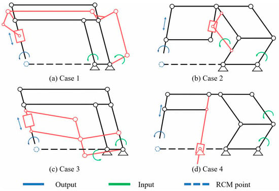
Figure 3.
Variation in the planar parallelogram mechanism with 1R1T RCMs.
All the mechanisms shown in Figure 3 are remote actuated, with the actuators mounted in proximity to the base. Note that in addition to the inputs marked in the figure, there are other alternative options for the active limbs.
Case 1 achieves translational motion by introducing a linear linkage mechanism, the central part of which is a crank-slider mechanism in proximity to the end instrument. Due to the characteristics of this mechanism, the slider exerts large stress on the end instrument, with large stress concentrations at adjacent joints when the transmission angle is relatively small. In addition, the rotational motion of the input needs to pass through multiple rotational joints before it can be converted into translational motion of the slider, which leads to more complex kinematics and poorer accuracy. Case 3 introduces additional parallelogram limb sets to realize the translational motion, and these are more stable and have simpler kinematics. However, the range of motion of these additional parallelograms is relatively large, which can seriously affect the operating space around the end instrument and cannot maintain a safe distance between limbs and the RCM point.
In addition, both Case 1 and Case 3 introduce a large number of limbs and rotational joints, which results in the need to apply more hinge connections, thus decreasing the stability of the robot and causing more assembly errors to accumulate at the end. Therefore, Case 2 and Case 4, with fewer limbs and joints, are more suitable for ophthalmic surgical robots.
The difference between Case 2 and Case 4 is that Case 4 achieves translational motion with an additional limb parallel to the end instruments, while the additional limbs in Case 2 do not have this feature, which can lead to the introduction of more angular variables in the kinematic calculations, thus complicating the kinematics. In addition, because the slider in Case 2 is mounted on a parallelogram limb set, its travel distance is constrained by the length of the associated limb, and when its travel distance is increased by increasing the size of the end parallelogram bar set, the operating space at the end is compressed. The slider in Case 4 is fixed to the base, thus ensuring a larger travel distance while maintaining enough operating space.
Combined with the previous analysis, Case 4 was chosen to synthesize the proposed mechanism. In addition, some other comparable 1R1T parallelogram mechanisms are available as alternatives but will not be discussed in detail here.
2.3. Kinematic Modeling and Analysis
As shown in Figure 2, the motions of the instrument tip at the end of the proposed mechanism around the RCM point are represented as α, β, and d, which are realized via combination of joint DOF expressed as θ1, θ2, and θ3.
The two rotational DOF, α and β, are realized by rotational joint 1 and rotational joint 2; more specifically, α is associated with θ2 and β is associated with θ1. The translational DOF, d, can be considered as the distance between the instrument tip and the RCM point, which is realized mainly by the structure of the 1R1T mechanism and thus is associated with both θ1 and θ3.
Annotated illustrations of the two planar mechanisms are provided in Figure 4 and Figure 5 for further analysis of the kinematics. Points of interest are indicated with capital letters, namely, joints A, B, C, D, E, F, G, H, I, J, K, L, M, N, P, Q, R, S, and T. All of them are rotational joints except for A, which is a joint containing both translational and rotational motions. The two mechanisms share the same point O, namely, the RCM point O in Figure 2.
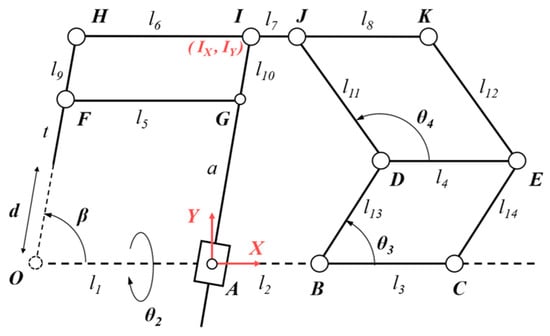
Figure 4.
Annotated overview of the planar 1R1T mechanism kinematics.
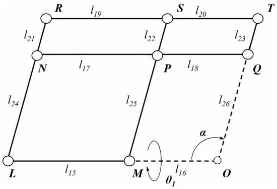
Figure 5.
Annotated overview of the planar 1R mechanism kinematics.
In addition to the parameters indicated in Figure 2, mechanism configuration parameters include linkage lengths l1……l26 and angle θ4. The length of the end surgical instrument (generally a surgical needle) is indicated as t. In particular, the distance between A and G is denoted as a, which is a variable length due to the translational joint at point A. Finally, for follow-up calculations, a coordinate frame is established at point A, and the coordinates of point I are expressed as .
From the properties of the parallelogram mechanism, the following equalities are given:
l1 = l5 = l6 l3 = l4 = l8 l9 = l10 l11 = l12 l13 = l14
l15 = l17 = l19 l16 = l18 = l20 l21 = l22 = l23 l24 = l25 = l26
It should be noted that when the 1R1T mechanism shown in Figure 4 works independently, θ3 and θ4 are generally chosen as inputs to control β and d. In the proposed spatial mechanism, however, β is controlled by rotating joint 1 and thus is determined by θ1. Therefore, β should be considered as an input parameter when analyzing the planar 1R1T mechanism separately. Similarly, α, which is controlled by θ2, should be regarded as an input parameter when analyzing the 1R mechanism shown in Figure 5 alone. Thus, for the mechanism shown in Figure 4, the actuating parameters are β and θ3, while θ4 is a passive DOF. It is certainly feasible to choose θ4 as the input and θ3 as the passive DOF, but choosing θ3 as the actuating parameter makes it easier to mount the actuator at the base.
2.4. Inverse Kinematics
A function of end-effector variables is applied to describe the motion of the proposed mechanism, where the resulting mechanism configuration is fully described by the input parameters .
For the convenience of calculation:
Obviously, the coordinates IX and IY of point I can be expressed as:
Given the geometric properties of the mechanism:
Using Equations (4)–(6), IX and IY can be expressed as functions of β and d as:
The same planar coordinates can also be expressed as functions of θ3 and θ4 as:
Using Equations (2)–(11), the inverse kinematics as defined in Equation (1) can be derived as:
Note that in Equation (13), IX and IY are written as functions of α and β, with the expressions given in Equations (7) and (8).
2.5. Forward Kinematics
A function of input parameters is applied to describe the motion of the proposed mechanism, where the resulting mechanism configuration is fully described by the end-effector variables :
As shown in Figure 6, an auxiliary line is added to help calculate the forward kinematics, and this is parallel to IA and intersects OC at point U. In addition, length parameters m, n, and p are added to denote the lengths of UB, UD, and UJ, as well as two angle parameters, denoted by γ and φ.
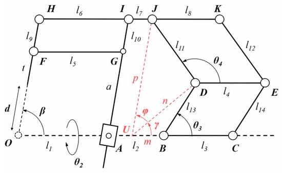
Figure 6.
Annotated overview of the planar 1R1T mechanism with auxiliary lines.
Taking the properties of the parallelogram AUJI, m and p can be expressed as:
In the triangle UBD, the length of edge UD, namely, parameter n, can be determined by applying the cosine theorem, with m expressed as Equation (15):
Using the cosine theorem again, γ can be expressed as:
In the triangle UDJ, the length of edge UJ, namely, parameter p, can be determined by applying the cosine theorem:
Angle φ can be expressed as:
Using Equations (2), (3), (6) and (15)–(20), the forward kinematics defined in Equation (14) can be derived as:
Note that in Equation (23), the ± sign in the formula is generally assumed to be +. Furthermore, to keep the mechanism gesture as shown in Figure 6 and ensure the continuity of control, Equations (2)–(23) are only valid under the following conditions:
2.6. Differential Kinematics
Differential kinematics describes the relationship between the end-effector velocity and the velocity at the input side. Since both and include three parameters, the relationship between them can be described by a 3 × 3 matrix, the elements of which can be obtained by taking partial derivatives of the input parameters.
For brevity, the detailed expressions for and are given in Appendix A.
2.7. Singularity
The analysis of the proposed mechanism leads to the existence of two singularities for each physical parallelogram, occurring when the linkages are colinear. In total, 10 singularities are identified.
To avoid singularities in the motion of the mechanism, the values of θ1, θ2, θ3, and θ4 are set as within the relationship given in Equation (24).
3. Workspace Analysis and Parameter Determination
3.1. Planar Workspace
An ideal workspace is proposed, representing a predictable planar workspace in subretinal surgery.
Subretinal surgery targets issues such as retinal macular degeneration, where the lesion is generally in the macular region [32] and the desired workspace in the fundus is determined by the location of the macula. Therefore, the range of possible locations of the macular region in the fundus needs to be analyzed.
As shown in Figure 7a, the eye is abstracted as a sphere with a diameter of approximately 24.2 mm. According to ocular anatomy, the line perpendicular to the cornea that intersects the center of the entrance pupil is called the pupillary axis, and the line connects the fovea to the center of the entrance pupil is called the line of sight [33]. The angle between the pupillary axis and the line of sight is called angle kappa, which varies in size depending on the individual. Based on the statistical data, the approximate range of angle kappa can be obtained, and thus the range of the fovea location. Since the fovea is the center of the macula, the possible location of the macula can be obtained by introducing the macular radius (RM) at the two limit positions where angle kappa takes the maximum value Kmax and the minimum value Kmin; thus, the planar workspace coverage at the fundus is confirmed.
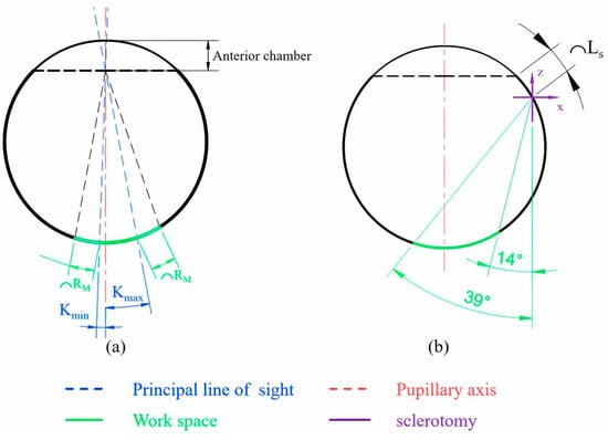
Figure 7.
Analysis of the desired planar workspace coverage. (a) Analysis of the target area; (b) the desired planar workspace.
Since the surgical instruments enter the vitreous through the scleral incision, it is necessary to consider the impact of the scleral incision location when calculating the robot workspace. As shown in Figure 7b, the workspace of the surgical instrument can be modified based on the length of the anterior chamber and the arc length LS from the scleral incision to the anterior aspect of the ciliary body.
A coordinate system was established at the scleral incision with the negative direction of the Y-axis as 0°. Based on ocular anatomy and ophthalmology statistics, the length of the anterior chamber is taken as 3.6 mm, Kmin as 2°, Kmax as 11°, RM as 3 mm, and LS as 3.2 mm [33,34,35,36]; then, the workspace coverage of the surgical instrument can be obtained as 14° to 39°.
As shown in Figure 8, the 1R1T plane mechanism is kept coplanar with the eye section and the scleral incision is set as the RCM point. Considering the error in practical application, a margin of 50% is added to the previous workspace range, and the modified range is from 8° to 46°, which gives a range for β from 44° to 82°.
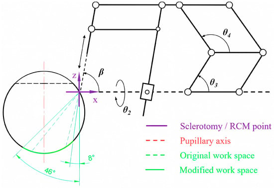
Figure 8.
Analysis of the planar workspace coverage with introduction of the 1R1T mechanism.
3.2. Parameter Analysis and Selection for the 1R1T Mechanism
3.2.1. Parameter Analysis and Kinematic Constraints
The parameters of the 1R1T planar mechanism are analyzed first. According to the equality relationship described in Section 2.3, the 1R1T mechanism can be described by parameters l1, l2, l3, l7, l10, l11, l13, and t. From the previous kinematic analysis, it is clear that l1 and l3 do not affect the output variables β and d. Therefore, the values can be selected directly. Based on the previously available relevant designs, l1 and l3 are selected:
l7 and l10 are mainly related to the interference of the mechanism limbs. To ensure the clearance between the linkages, l7 and l10 can be set as follows:
The remaining mechanism parameters l2, l11, l13, and t were set as discrete ranges with limits based on available relevant designs. The discretization step for l2, l11, and l13 is 5 mm, while the discretization step for t is 10 mm. The resulting 2268 different kinematic designs will be analyzed and selected in the following section:
With a defined parameter range, the range of input variables also needs to be limited. According to the kinematic analysis of the 1R1T mechanism, the variables that determine the output are θ1 and θ3, while θ4 varies with θ1 and θ3. From the singularity analysis, θ1, θ3, and θ4 take values between 0° and 180°. This range is further restricted to 10° to 170° to prevent collision and interference between the limbs, while the limit given in Equation (24) also needs to be ensured:
3.2.2. Analysis and Evaluation Methods
For the configuration to be analyzed, it should be ensured that its workspace can cover the target workspace given in the previous section while satisfying the kinematic constraints. In addition, the workspace should cover as much space as possible beyond the target workspace within the vitreoretinal area. On this basis, a brief procedure for analyzing and evaluating the configurations is given below:
- (1)
- For each configuration, calculate its workspace.
- (2)
- Eliminate the configurations that do not cover the targeted workspace.
- (3)
- Eliminate the configurations that do not satisfy the kinematic constraints.
- (4)
- For the qualified configurations, calculate their coverage of the non-targeted space within the vitreoretinal area.
- (5)
- Rank the coverage of the non-targeted area and output the configuration with the highest coverage.
When calculating the workspace based on forward kinematics, the input parameters need to be discretized; therefore, the output workspace is a discrete point cloud. While the discretization step for the input is an invariant constant, the point cloud has a nonuniform density, and it is therefore difficult to calculate its area.
To solve the bias caused by the varying point density, a grid-based sampling method is applied to divide the plane with a uniform grid. The output points lying in a single grid are replaced by the grid centroid; thus, a uniform point cloud is obtained, and the workspace could be calculated by accumulating the area of these grids.
In addition, angle θ4 needs to be evaluated before calculating the output, and if the result does not satisfy Equation (35), the output point will not be counted. The detailed formula for the calculation of θ4 will not be discussed for the sake of brevity.
3.2.3. Results
According to the analysis method above, the plane to be analyzed was divided using a grid with a single grid size of , and the input angles θ1 and θ3 were given a discretization step of 0.2° under the condition given in Equation (35). The maximum coverage of the target and non-targeted area in the eye that can be achieved for each parameter at different values is shown in Figure 9, and its trends with respect to the values are labeled. With these trends, it is possible to know the effect of the variation in the length of the individual parameters on the overall configuration workspace.
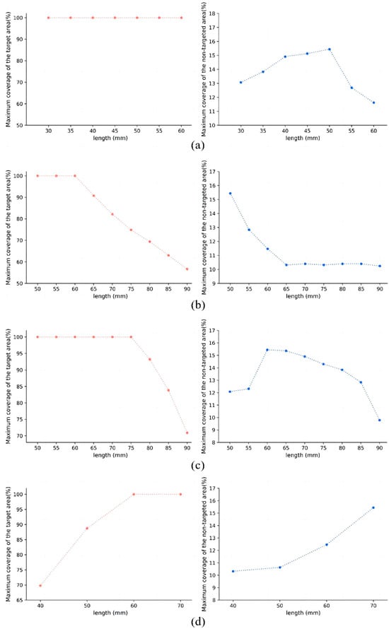
Figure 9.
Maximum coverage of each parameter at different values. (a) Maximum coverage of the target area and non-targeted area with l2 at different values; (b) maximum coverage of the target area and non-targeted area with l11 at different values; (c) maximum coverage of the target area and non-targeted area with l13 at different values; (d) maximum coverage of the target area and non-targeted area with t at different values.
When the required coverage of the target workspace is set to 90%, a total of 87 out of 2268 configurations meet the requirement. The non-targeted vitreoretinal area coverages of these configurations were ranked, and the optimal configuration was identified as:
The workspace simulation of this configuration is shown in Figure 10, where partial points at the periphery of the point cloud are removed for simplicity. The configuration has a target workspace coverage of 100%, with a 10.97% coverage of the non-targeted space within the vitreoretinal area. In total, its workspace coverage of the vitreoretinal area is 50.51%.
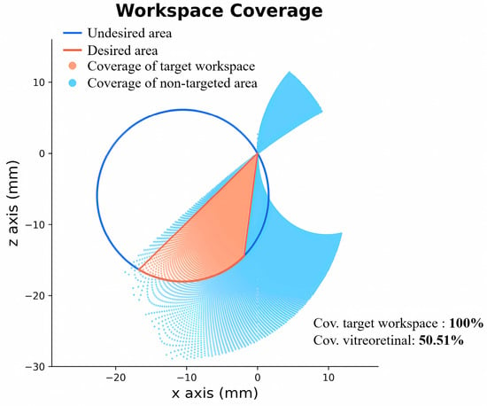
Figure 10.
Workspace coverage of the optimal configuration.
3.3. Three-Dimensional Workspace
As shown in Figure 2, a three-dimensional (3D) coordinate system is introduced with the RCM point as the origin, where the x-axis and y-axis, respectively, coincide with the rotation axes of the two rotary joints on the base. The origin point is set to coincide with the scleral incision on the virtual eye to analyze the 3D workspace of the 2R1T mechanism.
First, the range of the three input parameters needs to be determined. Angles θ1 and θ3 still adopt the range given in Equation (35), while θ2 takes the following range:
The 3D workspace is represented by a spatial point cloud, which is generated based on the forward kinematics given in Equations (2) and (3), and the discretization step of angles θ1, θ2, and θ3 is set to 0.5° in the simulation. The simulation result is shown in Figure 11a, where the peripheral scatter points have been removed for brevity. Figure 11b,c show the projections of the 3D workspace in XY and YZ planes. It can be seen that the workspace of the mechanism has a sufficiently large coverage inside the eye; therefore, the mechanism can be considered to meet the requirements of the general vitreoretinal surgery for the workspace coverage.
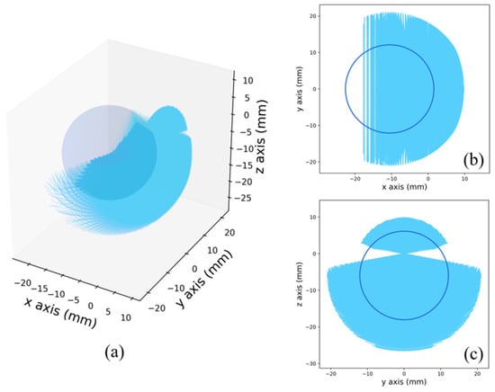
Figure 11.
Workspace simulation of the 2R1T mechanism. (a) 3D workspace; (b) workspace projection in the XY plane; (c) workspace projection in the YZ plane.
4. Prototype
To validate the design, a prototype was built based on the final mechanism, as shown in Figure 12. The prototype has three DOF and is controlled by three motors. Note that the end of the prototype is not a real surgical instrument but a 3D printed plastic needle. A schematic diagram of the usage method of the mechanism is shown in Figure 13 with an equal proportion model of the human head.
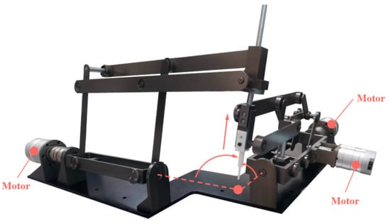
Figure 12.
Prototype of the final mechanism.
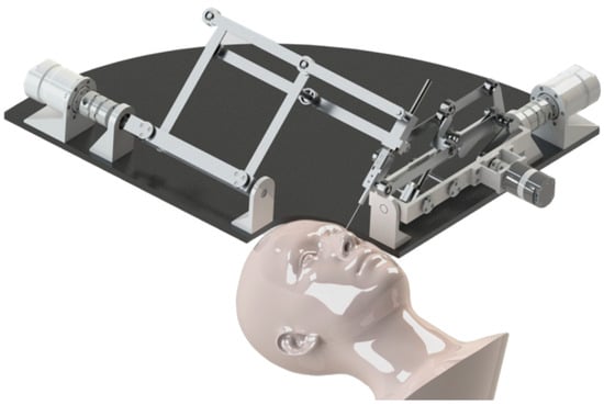
Figure 13.
Schematic diagram of the prototype.
The motions of the mechanism were validated on the prototype and the results are shown in Figure 14, Figure 15 and Figure 16. Figure 14 demonstrates the translational motion of the 1R1T mechanism. Figure 15 demonstrates the rotational motion of the 1R1T mechanism with a range from 40° to 89°, which satisfies the required workspace of the 1R1T planar mechanism. Figure 16 illustrates the rotational motion of the 1R mechanism. The results above show that the prototype has RCM and can meet the requirements of its workspace. Future research will further optimize the mechanical structure and control algorithm to improve the accuracy of the prototype.

Figure 14.
Translational motion of the 1R1T mechanism.
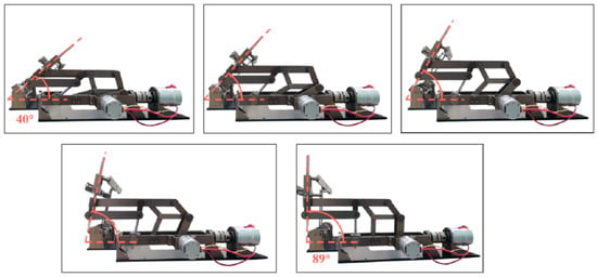
Figure 15.
Rotational motion of the 1R1T mechanism.
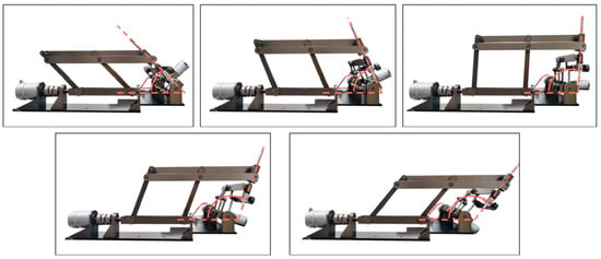
Figure 16.
Rotational motion of the 1R mechanism.
5. Conclusions
In this paper, a novel 2R1T RCM mechanism was designed based on the parallelogram mechanism. The developed mechanical structure design had all the actuators placed at the distal end of the base, and there was no excessive kinematic coupling, which makes the kinematics relatively simple and easier to control. The forward kinematics, inverse kinematics, and differential kinematics of the mechanism were analyzed, and angular relationships in the motion were presented and singularities were analyzed. The planar workspace was analyzed and accurately sketched based on ocular anatomy, depending on the requirements of MIOS. The optimal configuration was selected, and its workspace was obtained. Finally, a prototype was built to validate its motion.
Author Contributions
Y.L. designed and analyzed the proposed mechanism and was a major contributor in writing the manuscript. S.W., T.J. and J.F. participated in building the prototype and writing the control program. G.S. checked and revised the manuscript. All authors have read and agreed to the published version of the manuscript.
Funding
The authors would like to acknowledge the financial support of the following foundations: National Key R&D Program of China, Grant Nos. 2021YFF0700503. CAS Project for Young Scientists in Basic Research, Grant Nos. YSBR-067. Jiangsu Science and Technology Plan Program, Grant Nos. BK20220263. National Key R&D Program of China, Grant Nos. 2022YFC2404201.
Data Availability Statement
The data that support the findings of this study are available from the corresponding author, upon reasonable request.
Conflicts of Interest
The authors declare no conflict of interest.
Appendix A. Detailed Expressions for the Jacobian Matrix
Note that in the calculation of the above expression, the ± sign in Equation (23) is +.
References
- Nuzzi, R.; Brusasco, L. State of the art of robotic surgery related to vision: Brain and eye applications of newly available devices. Eye Brain 2018, 10, 13–24. [Google Scholar] [CrossRef] [PubMed]
- Ribeiro, L.; Oliveira, J.; Kuroiwa, D.; Kolko, M.; Fernandes, R.; Junior, O.; Moraes, N.; Vasconcelos, H.; Oliveira, T.; Maia, M. Advances in vitreoretinal surgery. J. Clin. Med. 2022, 11, 6428. [Google Scholar] [CrossRef] [PubMed]
- Kuo, C.; Dai, J.S.; Dasgupta, P. Kinematic design considerations for minimally invasive surgical robots: An overview. Int. J. Med. Robot. Comput. Assist. Surg. 2012, 8, 127–145. [Google Scholar] [CrossRef] [PubMed]
- Taylor, R.; Stoianovici, D. Medical robotics in computer-integrated surgery. IEEE Trans. Robot. Autom. 2003, 19, 765–781. [Google Scholar] [CrossRef]
- Rahimy, E.; Wilson, J.; Tsao, T.-C.; Schwartz, S.; Hubschman, J.-P. Robot-assisted intraocular surgery: Development of the IRISS and feasibility studies in an animal model. Eye 2013, 27, 972–978. [Google Scholar] [CrossRef] [PubMed]
- Molaei, A.; Abedloo, E.; Taghirad, H.D.; Marvi, Z. Kinematic and workspace analysis of diamond: An innovative eye surgery robot. In Proceedings of the Iranian Conference on Electrical Engineering, Tehran, Iran, 10–14 May 2015; pp. 882–887. [Google Scholar]
- Tsukimoto, Y.; Kawai, T.; Nishikawa, A.; Nishizawa, Y.; Nakamura, T. Surgical assistant manipulator with rack gear and gear train mechanism for laparoscopic surgery. In Proceedings of the IEEE/SICE International Symposium on System Integration, Narvik, Norway, 9–12 January 2022; pp. 60–64. [Google Scholar] [CrossRef]
- Zong, G.; Pei, X.; Yu, J.; Bi, S. Classification and type synthesis of 1-DOF remote center of motion mechanisms. Mech. Mach. Theory 2008, 43, 1585–1595. [Google Scholar] [CrossRef]
- Taylor, R.H.; Funda, J.; Grossman, D.D.; Karidis, J.P.; LaRose, D.A. Remote Center-of-Motion Robot for Surgery. U.S. Patent 5,397,323, 14 March 1995. [Google Scholar]
- Taylor, R.; Funda, J.; Eldridge, B.; Gomory, S.; Gruben, K.; LaRose, D.; Talamini, M.; Kavoussi, L.; Anderson, J. A telerobotic assistant for laparoscopic surgery. IEEE Eng. Med. Biol. Mag. 1995, 14, 279–288. [Google Scholar] [CrossRef]
- He, C.-Y.; Huang, L.; Yang, Y.; Liang, Q.-F.; Li, Y.-K. Research and realization of a master-slave robotic system for retinal vascular bypass surgery. Chin. J. Mech. Eng. 2019, 31, 78. [Google Scholar] [CrossRef]
- Wang, N.; Zhang, X.; Li, M.; Zhang, H.; Stoyanov, D.; Stilli, A. A 5-DOFs robot for posterior segment eye microsurgery. IEEE Robot. Autom. Lett. 2022, 7, 10128–10135. [Google Scholar] [CrossRef]
- Channa, R.; Iordachita, I.; Handa, J.T. Robotic vitreoretinal surgery. Retin. J. Retin. Vitr. Dis. 2017, 37, 1220–1228. [Google Scholar] [CrossRef]
- Zong, G. Design of double parallelogram remote-center-of-motion mechanisms. Chin. J. Mech. Eng. 2007, 43, 103–108. [Google Scholar] [CrossRef]
- Huang, L.; Yang, Y.; Xiao, J.J.; Su, P. Type synthesis of 1r1t remote center of motion mechanisms based on pantograph mechanisms. J. Mech. Des. 2016, 138, 014501. [Google Scholar] [CrossRef]
- Smits, J.; Reynaerts, D.; Poorten, E.V. Synthesis and methodology for optimal design of a parallel remote center of motion mechanism: Application to robotic eye surgery. Mech. Mach. Theory 2020, 151, 103896. [Google Scholar] [CrossRef]
- Lin, R.; Guo, W.; Cheng, S.S. Type synthesis of 2R1T remote center of motion parallel mechanisms with a passive limb for minimally invasive surgical robot. Mech. Mach. Theory 2022, 172, 104766. [Google Scholar] [CrossRef]
- Zhang, F.; Zhang, X.; Hang, L.; Lu, C.; Furukawa, T. Type Synthesis of N-Parallelogram-Based Surgical Arm with Remote Actuated Configuration; Lecture Notes in Electrical Engineering; Springer: Singapore, 2017; Volume 408, pp. 183–194. [Google Scholar] [CrossRef]
- Gijbels, A.; Wouters, N.; Stalmans, P.; Van Brussel, H.; Reynaerts, D.; Poorten, E.V. Design and realization of a novel robotic manipulator for retinal surgery. In Proceedings of the IEEE/RSJ International Conference on Intelligent Robots and Systems (IROS), Tokyo, Japan, 3–7 November 2013; pp. 3598–3603. [Google Scholar]
- Ourak, M.; Smits, J.; Esteveny, L.; Borghesan, G.; Gijbels, A.; Schoevaerdts, L.; Douven, Y.; Scholtes, J.; Lankenau, E.; Eixmann, T.; et al. Combined OCT distance and FBG force sensing cannulation needle for retinal vein cannulation: In vivo animal validation. Int. J. Comput. Assist. Radiol. Surg. 2019, 14, 301–309. [Google Scholar] [CrossRef] [PubMed]
- Gijbels, A.; Smits, J.; Schoevaerdts, L.; Willekens, K.; Poorten, E.B.V.; Stalmans, P.; Reynaerts, D. In-human robot-assisted retinal vein cannulation, a world first. Ann. Biomed. Eng. 2018, 46, 1676–1685. [Google Scholar] [CrossRef] [PubMed]
- Chen, G.; Wang, J.; Wang, H. A new type of planar two degree-of-freedom remote center-of-motion mechanism inspired by the Peaucellier-Lipkin straight-line linkage. J. Mech. Des. 2018, 141, 015001. [Google Scholar] [CrossRef]
- Ye, W.; Zhang, B.; Li, Q.C. Design of a 1R1T planar mechanism with remote center of motion. Mech. Mach. Theory 2020, 149, 103845. [Google Scholar] [CrossRef]
- Liu, S.T.; Harewood, L.; Chen, B.; Chen, C. A skeletal prototype of surgical arm based on dual-triangular mechanism. J. Mech. Robot.-Trans. ASME 2016, 8, 041015. [Google Scholar] [CrossRef]
- Jingjing, X.; Long, H.; Lijun, S.; Yang, Y. Design and research of a robotic aided system for retinal vascular bypass surgery. J. Med Devices-Trans. ASME 2014, 8, 044501. [Google Scholar] [CrossRef]
- Yan, C.; Liu, M.; Shi, G.; Fan, J.; Li, Y.; Wu, S.; Hu, J. Design of a subretinal injection robot based on the rcm mechanism. Micromachines 2023, 14, 1998. [Google Scholar] [CrossRef] [PubMed]
- He, Y.; Zhang, P.; Jin, H.; Hu, Y.; Zhang, J. Type synthesis for remote center of motion mechanisms based on coupled motion of two degrees-of-freedom. J. Mech. Des. 2017, 138, 122301. [Google Scholar] [CrossRef]
- Liu, S.; Chen, B.; Caro, S.; Briot, S.; Harewood, L.; Chen, C. A cable linkage with remote centre of motion. Mech. Mach. Theory 2016, 105, 583–605. [Google Scholar] [CrossRef]
- Huang, L.; Yin, L.; Liu, B.; Yang, Y. Design and error evaluation of planar 2dof remote center of motion mechanisms with cable transmissions. J. Mech. Des. 2020, 143, 013301. [Google Scholar] [CrossRef]
- Wang, Z.; Zhang, W.; Ding, X. Design and analysis of a novel mechanism with a two-DOF remote centre of motion. Mech. Mach. Theory 2021, 153, 103990. [Google Scholar] [CrossRef]
- Chen, G.; Wang, J.; Wang, H.; Chen, C.; Parenti-Castelli, V.; Angeles, J. Design and validation of a spatial two-limb 3R1T parallel manipulator with remote center-of-motion. Mech. Mach. Theory 2020, 149, 103807. [Google Scholar] [CrossRef]
- Sarks, J.P.; Sarks, S.H.; Killingsworth, M.C. Evolution of geographic atrophy of the retinal-pigment epithelium. Eye 1988, 2, 552–577. [Google Scholar] [CrossRef] [PubMed]
- Artal, P. Optics of the eye and its impact in vision: A tutorial. Adv. Opt. Photonics 2014, 6, 340–367. [Google Scholar] [CrossRef]
- Hashemi, H.; KhabazKhoob, M.; Yazdani, K.; Mehravaran, S.; Jafarzadehpur, E.; Fotouhi, A. Distribution of angle Kappa measurements with orbscan II in a population-based survey. J. Refract. Surg. 2010, 26, 966–971. [Google Scholar] [CrossRef]
- Malhotra, A.; Minja, F.J.; Crum, A.; Burrowes, D. Ocular anatomy and cross-sectional imaging of the eye. Semin. Ultrasound CT MRI 2011, 32, 2–13. [Google Scholar] [CrossRef]
- Lemley, C.A.; Han, D.P. An age-based method for planning sclerotomy placement during pediatric vitrectomy: A 12-year experience. Retin. J. Retin. Vitr. Dis. 2007, 27, 974–977. [Google Scholar] [CrossRef] [PubMed]
Disclaimer/Publisher’s Note: The statements, opinions and data contained in all publications are solely those of the individual author(s) and contributor(s) and not of MDPI and/or the editor(s). MDPI and/or the editor(s) disclaim responsibility for any injury to people or property resulting from any ideas, methods, instructions or products referred to in the content. |
© 2024 by the authors. Licensee MDPI, Basel, Switzerland. This article is an open access article distributed under the terms and conditions of the Creative Commons Attribution (CC BY) license (https://creativecommons.org/licenses/by/4.0/).