Article

Diagnosis of Power Switch Faults in Three-Phase Permanent Magnet Synchronous Motors via Current-Signature Technique

by
Aleksander Suti
* and
Gianpietro Di Rito
Dipartimento di Ingegneria Civile ed Industriale, Università di Pisa, Largo Lucio Lazzarino 2, 56122 Pisa, Italy
*
Author to whom correspondence should be addressed.
Actuators 2024, 13(1), 25; https://doi.org/10.3390/act13010025
Submission received: 22 November 2023 / Revised: 29 December 2023 / Accepted: 4 January 2024 / Published: 8 January 2024

Abstract

:
The paper deals with the development of a model-based current-signature algorithm for the detection and isolation of power switch faults in three-phase Permanent Magnet Synchronous Motors (PMSMs). The algorithm, by elaborating the motor currents feedbacks, reconstructs the current phasor trajectories in the Clarke plane through elliptical fittings, up to detecting and isolating the fault depending on the characteristics of the signature deviation from the nominal one. As a rough approximation, as typically proposed in the literature, the fault of one out of six power switches implies that, at constant speed operation, the phasor trajectory deviates from the nominal circular path up to a semi-circular “D-shape” signature, the inclination of which depends on the failed converter leg. However, this evolution can significantly deviate in practical cases, due to the dynamics related to the transition of motor phase connections from failed to active switches. The study demonstrates that an online ellipse fitting of the current signature can be effective for diagnosis, through correlating the ellipse centre to the location of the failed switch. The performances of the proposed monitoring technique are here assessed via the nonlinear simulation of a PMSM employed for the propulsion of a lightweight fixed-wing Unmanned Aerial Vehicle (UAV), by quantifying the fault latencies and the related transients.

1. Introduction

One of the most challenging goals in the design of airborne vehicles, in aligning with the worldwide initiatives for transports decarbonisation, is the electrification of propulsion systems. Concerning long-endurance UAVs, hybrid-electric and Full-Electric Propulsion System (FEPS) concepts are gaining wide investments in order to progressively replace Internal Combustion Engines (ICEs). Electrification aims to reduce (and even eliminate in the case of FEPSs) CO2 emissions, abating thermal signatures, mitigating noise emissions, and enhancing thrust efficiency [1,2,3]. However, flight endurance and reliability still remain open issues. Endurance is currently limited by the capability of the energy storage devices, which is much lower than ICEs (the capacity of Li-Ion batteries is typically about 0.3 MJ/kg, approximately 100 times lower than gasoline [1]). In addition, due to the novelty of this application, the reliability and safety are still questionable. The failure rate of three-phase Permanent Magnet Synchronous Motors (PMSMs) with conventional three-leg converters is typically around 200 per million flight hours [4,5], which is far from the required levels for airworthiness certification [6]. Specifically, a relevant amount (from 50% to 70%) of PMSMs fault modes originate from motor phases (open-phase [5], inter-turn [7], phase-to-phase [8] and phase-to-ground [9]) and power converters. Among the latter ones, faults of the supply voltage stabilizing capacitor and faults of the power switches are predominant [10,11].
The main fault modes in converter capacitors are the short circuit and the dielectric breakdown. Commonly, the effects of these faults are covered by capacitor redundancy with series-parallel topologies, preventing the faults’ extension to other elements (short-circuit) as well as the complete loss of functionality (dielectric breakdown) [12,13].
Power switch faults can be open-circuit- or short-circuit-related. The latter, characterised by fast transients with the generation of relevant current peaks, require immediate detection and isolation; modern converters are equipped with hardware protection, such as fast fuses, permitting the transformation of the effects of a short-circuit into those of an open-circuit [14]. Though the open-circuit of a power switch avoids current inrush phenomena, they result in current distortions, torque ripple and overheating, such that, if undetected, they can lead to anomalous operation or secondary faults.
A common approach to enhancing reliability involves the implementation of hardware redundancies (e.g., redundant motors or drives), but this solution is often unfeasible in UAV applications, due to stringent weight and envelope requirements. As a consequence, the application of hardware redundancy is typically limited to motor phases (using multiple stator modules or multiple phases [9,15]) and/or to converter legs (using unconventional converters [16]).
A relevant example of an unconventional converter is given by the four-leg topology [5,17,18] shown in Figure 1. In this architecture, a stand-by leg with two switches is integrated alongside the three-leg bridge, so that, in the case of a fault in one out of the six main switches, the redundant leg can be connected to a phase terminal, permitting fault accommodation. The development of accurate and rapid Fault-Detection and Isolation (FDI) algorithms is clearly crucial to leverage any fault-tolerant capability, especially for PMSMs operating at high speeds, in which the FDI algorithms must work at very high sampling rates [19].
Comprehensive reviews of diagnostic methods for PMSM drives are presented by Orlowsca-Kowalska et al. in [13] and by Liang et al. in [20], who show that the diagnosis of power switch open-circuits can be categorised into current-based [21,22,23,24,25,26,27,28,29,30,31,32,33,34,35,36,37] and voltage-based methods [38,39,40,41]. Both methods are further classified into three categories (Table 1):
  • Model-based methods;
  • Signal-based methods;
  • Data-driven methods.
Voltage-based methods, though characterised by faster fault detection and reduced false alarms, typically require the addition of dedicated components into the control electronics, such as voltage sensors and analogue-to-digital converters, increasing the system cost and complexity. An interesting exception has been recently presented in [41], where an open-circuit diagnosis is obtained from voltage residual analysis without additional sensors, thanks to the analysis of DC and second-harmonic components of the residuals between the estimated and reference voltages.
Conversely, current-based methods are more convenient since they use measurements that are already available in conventional control units. Several current-based methods have been proposed in the literature. A Kalman-filter-based method is proposed in [21] to estimate the three-phase currents of the motor; residual signals are defined as the difference between the measured and estimated stator currents and the averaged normalised residuals are used as fault symptoms for the open-switch fault. A model-based observer is used in [22] to design a sliding-mode estimator of phase currents; the model measures the similarity between the estimated currents and the real ones using cross-correlation factors, which are used as fault symptoms. A fault diagnosis based on differential observer residuals, combined with detection thresholds to strengthen the method against model errors, is studied in [23]. Kiselev et al. [24] propose finite-control-set model predictive control to identify and compensate for the open-switch fault; the predicted variables are used as fault symptoms and, in the case of a fault, the system is accommodated for with prediction updates thanks to a four-leg converter. Similarly, in [25], the variation in the cost function generated by a model predictive control strategy is used as a fault symptom; the polarities of the average values of the currents in the Clarke-plane, combined with the phase angles of residual currents phasors, are used to locate the failed switch. A different approach is proposed in [26], where diagnosis is based on the application of Fourier series analysis; the fault symptom is here the ratio of the amplitudes of positive and negative sequence currents, and the fault isolation is obtained by evaluating the polarities of the DC components of currents in the stator reference frame. In [27], the FDI combines the use of normalised average values of the phase currents with three variables corresponding to the normalised average values of the product of two currents from different phases. Another observer-based method analysing the residuals between the reference and predicted currents is proposed in [28]; for each phase, two fault symptoms are defined to diagnose single or multiple open-circuits, and a fuzzy logic technique is applied for fault isolation. A more recent approach based on the so-called grey prediction theory is then presented in [29], in which the difference between the predicted and the actual current of a motor phase is used as a fault symptom. In another recent work [30], Zhang proposed detecting and isolating the open-circuit switch by evaluating the trends (i.e., constant, rising or falling) of the derivative of phase currents over a sliding time window; excluding dead-zone time, the fault is detected when a constant trend is obtained. In terms of FDI performances, this method is one of the fastest ones (the fault latency is about a 1/8 electric cycle), but the technique’s effectiveness is not demonstrated for high-speed applications.
Among the current-based methods, a special mention should be given to those using the so-called current-signature technique, based on the reconstruction and analysis of the current phasor trajectory (i.e., the signature) in the Clarke plane. A finite-control-set model for predictive control, applying the current-signature, is proposed in [31], where the fault symptom is the deviation of an average cost function derived from the current signature. Im et al. [32] propose a comparison between Park’s vector [33] and normalised DC current methods [34] for detecting power switch open-circuits; both methods are based on the average value of currents in one cycle, but the normalised DC current method is demonstrated to be more robust against load variations. A different approach is presented in [35], leveraging the fact that the currents running in two phases are in normal conditions associated by an elliptical relationship, while the trajectory deviates in the case of power switch faults. Trabelsi et al. [36] propose an algorithm that enables diagnosis by elaborating the slope of the current phasor trajectory (indicating the failed leg) together with signals from a Schmitt trigger (indicating the phase current polarity). More recently, Sun et al. [37] proposed a diagnosis in which the fault symptoms are extracted from the calculation of trend lines of the current signature in the Clark plane; in particular, the fault is detected when the difference in the slopes related to two consecutive trend lines is constant.
The main limitations of these methods are that their effectiveness is demonstrated for low-speed motors only, and that, in most cases, they are valid in detecting the open-circuits of power switches only. Applications for UAV propulsion are instead characterised by high-speed operations, with electrical frequencies exceeding 500 Hz, and the weight and envelope constraints implicitly require limiting the computational efforts related to FDI algorithms, the fault coverage of which must be as extensive as possible.
In this paper, an innovative current-based method applying the current-signature technique is proposed for the FDI of open-circuits in converter power switches, achieving the following main contributions:
  • The developed method relies on online ellipse fittings of the current phasor trajectory in the Clarke plane during constant speed operations of the motor, using the geometrical characteristics of the reconstructed ellipse as fault symptoms. The FDI algorithm elaborates the minimum number of measurements that permits the detection and isolation of the fault within a fraction of the electric period;
  • The algorithm, formerly adopted in a previous work by the authors, for the FDI of inter-turn short-circuits of PMSM phases [42] is here extended to power switch faults;
  • As a relevant case study, the FDI performances are assessed by simulating the failure transients related to power switch faults in a high-speed PMSM employed for the propulsion of a modern lightweight fixed-wing UAV.
The paper is structured as follows: the initial section presents the dynamic model of the PMSM; the FDI algorithm is then presented, emphasizing its basic design criteria; and, finally, a summary of the simulation results is presented and discussed, with specific attention to failure transient characterisation.

2. Materials and Methods

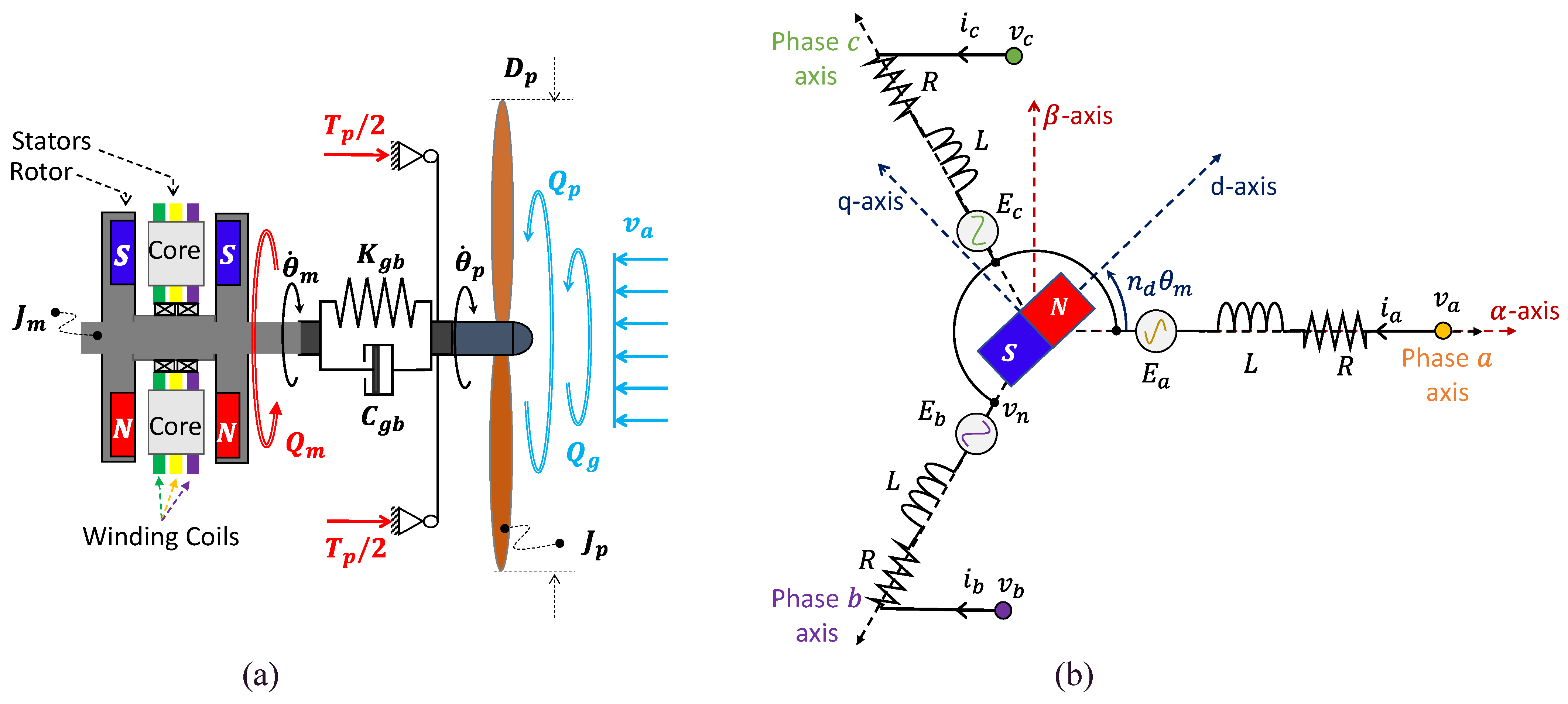
2.1. PMSM Electrical Modelling

The three-phase current dynamics of a PMSM with surface-mounted magnets can be modelled in vectorised form by using the following equations [15,16]:
v a b c = R i a b c + L d i a b c d t + e a b c ,
e a b c = k m θ ˙ m k a b c ,
in which v a b c = v a v n , v b v n , v c v n T is the applied voltages vector, i a b c = i a , i b , i c T is the stator currents vector, e a b c is the Back Electromotive Force (BEMF) vector, R and L are the resistance and inductance of the phases, θ ˙ m is the mechanical speed, k m is the motor speed constant and k a b c = k a ,   k b ,   k c T is the BEMF waveforms vector, the components of which for sinusoidal magnetic couplings are as follows:
k a = sin n d θ m , k b = sin n d θ m 2 3 π , k c = sin n d θ m + 2 3 π
where n d is the number of pole pairs.
The analysis of three-phase PMSMs is conventionally carried out by calculating magnetic and electrical quantities in the rotating reference frame, by applying the Clarke–Park transformations [16]. Actually, after defining a stator-referenced vector x a b c and the electrical angle θ e ( θ e = n d θ m ), we can insert it into the Clarke plane ( x α β γ ) via Equation (4) and into the Clarke-Park rotating frame ( x d q z ) via Equation (5), using the transformation matrices T C and T P C , respectively.
x α β γ = T C x a b c = 2 3 1 1 / 2 1 / 2 0 3 / 2 3 / 2 2 / 2 2 / 2 2 / 2 x a b c ,
x d q z = T P x α β γ = cos θ e sin θ e 0 sin θ e cos θ e 0 0 0 1 x α β γ = T P T C x a b c = T P C x a b c .

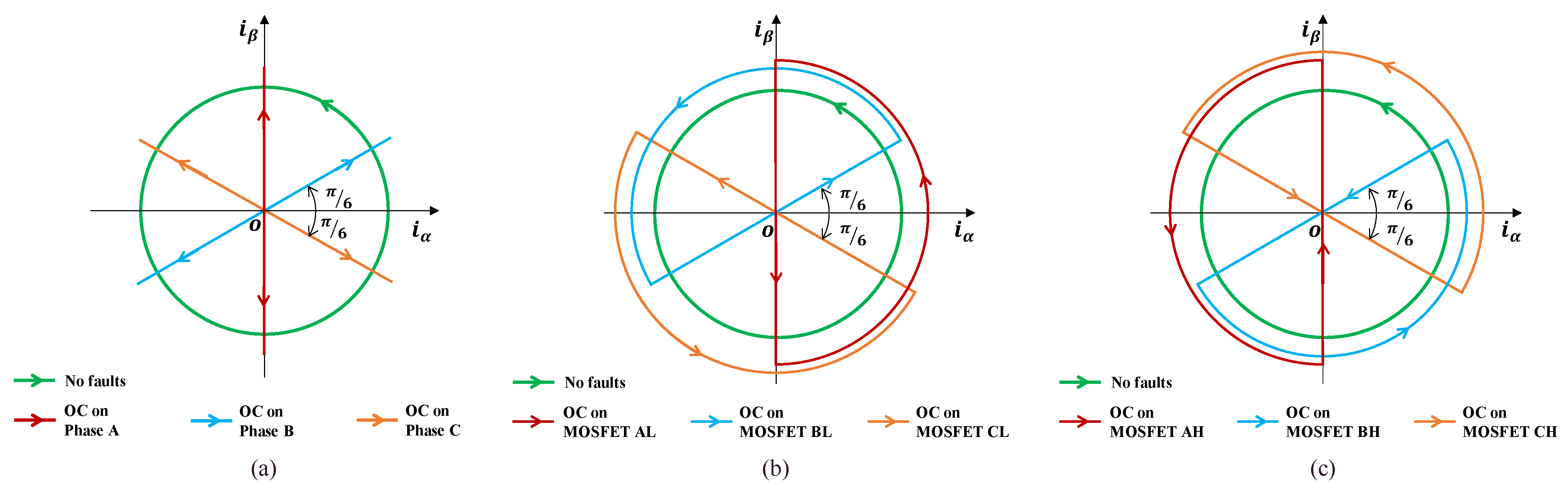
2.2. Current Signature in Clarke Plane in Case of Open-Circuit Power Switches

2.2.1. Behaviour with Open-Circuit of a Motor Phase

In normal conditions, when the motor rotates at a constant speed, the current phasor in the Clarke plane tracks a circular trajectory centred in the origin, as described in Equation (6):
i α 2 + i β 2 = 3 2 I 2    
in which I is the phase current amplitude, i α and i β are the components of the current phasor in the Clarke plane and 3 / 2 I is the radius of the circular trajectory of the current phasor. On the other hand, if a motor open-phase occurs, rectilinear trajectories are nominally tracked, as (through Equation (4)) given by Equations (7)–(9) (see Figure 2a):
      i β = 2 i b ¸   i α = 0                 i f       i a = 0      
i β = 1 3 i α                           i f       i b = 0
i β = 1 3   i α                       i f       i c = 0

2.2.2. Behaviour with Open-Circuit of a Power Switch

When an open-circuit occurs in one of the six power switches of the converter, the corresponding phase current can be either positive or negative, depending on the failed MOSFET. Thus, the phasor trajectory in the Clarke plane nominally collapses into a piecewise “D-shaped” track, given by the combination of a rectilinear part (due to the absence of conduction in the failed MOSFET, Section 2.2.1) and a semi-circular part (when the failed MOSFET is not required to conduct) (see Figure 2b,c).
The trajectory equations related to each MOSFET fault are reported in Table 2.

2.3. Fault Diagnosis

The basic idea underlying the proposed FDI algorithm is that a piecewise “D-shaped” track in the Clarke plane can be fitted by a decentred ellipse (see Figure 3a). The fault symptoms of the algorithm are, thus, the geometric characteristics of the current phasor trajectory, as schematically reported in the flow chart in Figure 3b, such that
The difference between the lengths of major and minor axes of the ellipse ( s M and s m , respectively) provides a symptom of a fault detection;
The coordinates of the ellipse centre ( i α 0 and i β 0 , respectively) univocally identify the failed switch.
Since the strategy is based on the identification of geometrical properties of an ellipse, one of the main problems deals with the determination of the minimum number of phasor points (each one related to three measurements of currents (Equation (4)) required for an adequate fitting. Although six phasor points theoretically permit the reconstruction of an ellipse, an over-sampling is necessary to compensate for noise, resolution and transient dynamics, so that the fitting problem becomes over-determined. The solution of these problems, usually obtained via iterative nonlinear methods, is here solved via a partitioning direct least-square-based technique, as proposed by Fitzgibbon [43] and then improved by Halir et al. [44], to obtain a more robust and computationally effective algorithm.
Once given the conic definition of an ellipse,
A α 2 + B α β + C β 2 + D α + E β + F = 0 B 2 4 A C < 0 ,
where α and β are, here, the coordinates of the ellipse points in the Clarke plane and A ,   B , C , D , E , F T = γ is the ellipse coefficients vector; the over-determined problem of fitting an ellipse to a set of coordinate points α i and β i (where i = 1 , ,   n , and n is greater than the number of ellipse coefficients, i.e., n > 6) can be solved by the eigenvalues problem in Equations (11)–(16) [42,44]:
M γ 1 = λ γ 1 γ 1 T C 1 γ 1 = 1 γ 2 = S 3 1 S 2 T γ 1 γ = γ 1 γ 2 T ,
M = C 1 1 S 1 S 2 S 3 1 S 2 T ,
S 1 = D 1 T D 1 ,   S 2 = D 1 T D 2 ,   S 3 = D 2 T D 2 , ,
D 1 = α 1 2 α 1 β 1 β 1 2 α n 2 α n β n β n 2 , D 2 = α 1 β 1 1 α n β n 1 ,
C 1 = 0 0 2 0 1 0 2 0 0 ,
γ = γ 1   γ 2 T ,
where M is the reduced scatter matrix and the ellipse coefficient vector γ is segmented into γ 1 = A B C T and γ 2 = D E F T .
After obtaining the solution of Equation (14), corresponding to the eigenvector γ yielding a minimal non-negative eigenvalue λ , the ellipse parameters are derived by the following [45]:
s M , m = 2 A E 2 + C D 2 B D E + B 2 4 A C F A + C ±   A C 2 + B 2 4 A C B 2 ,
i α 0 = 2 C D B E B 2 4 A C   ,     i β 0 = 2 A E B D B 2 4 A C .

2.4. Application to a PMSM for Lightweight Fixed-Wing UAV Propulsion

The reference propulsion system, designed for the full-electric propulsion of a modern lightweight UAV, is composed of the following:
  • An electronic control section, including the following (Figure 4):
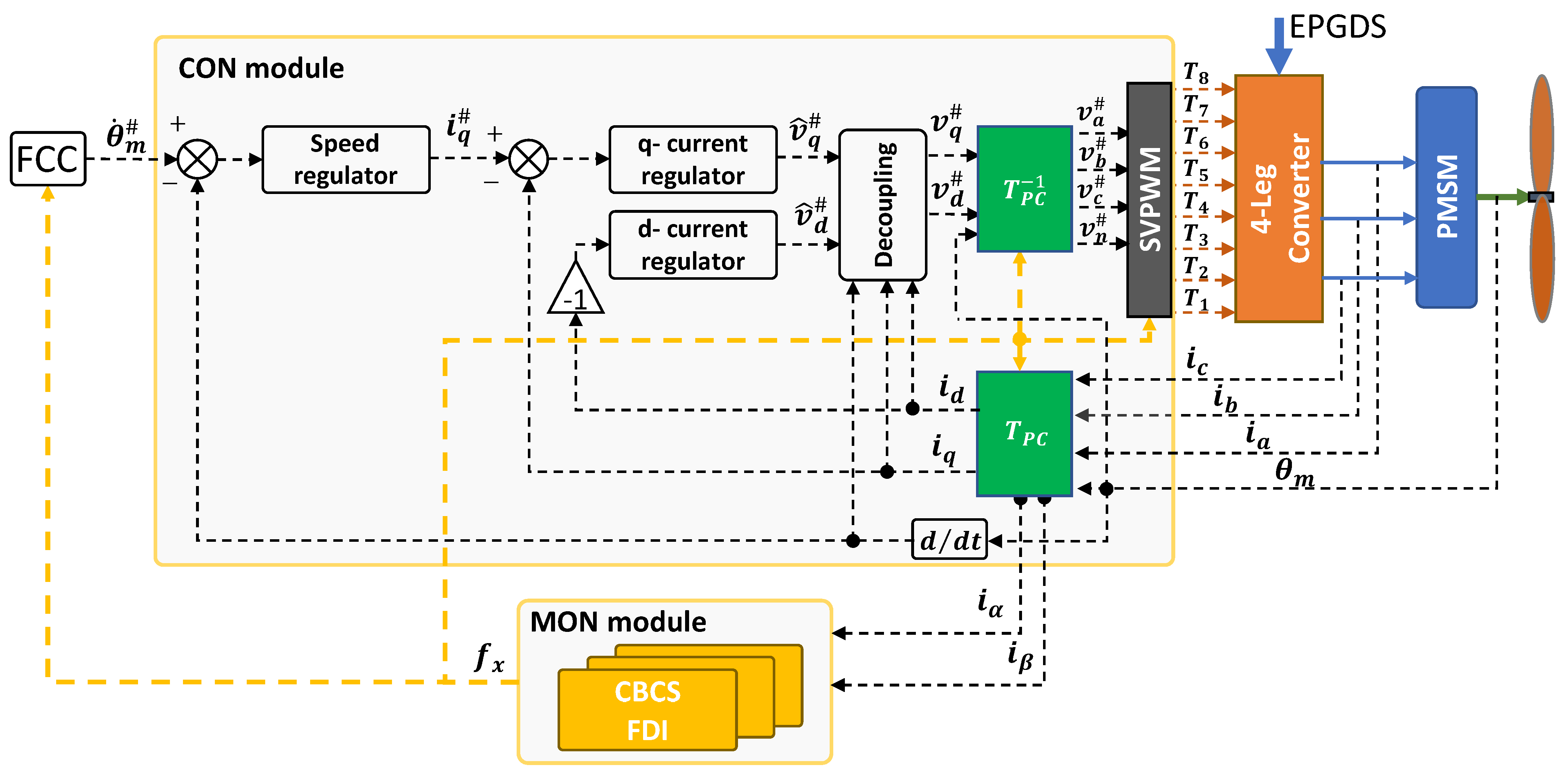
    A control/monitoring electronic box, for the implementation of the closed-loop control and health-monitoring functions;
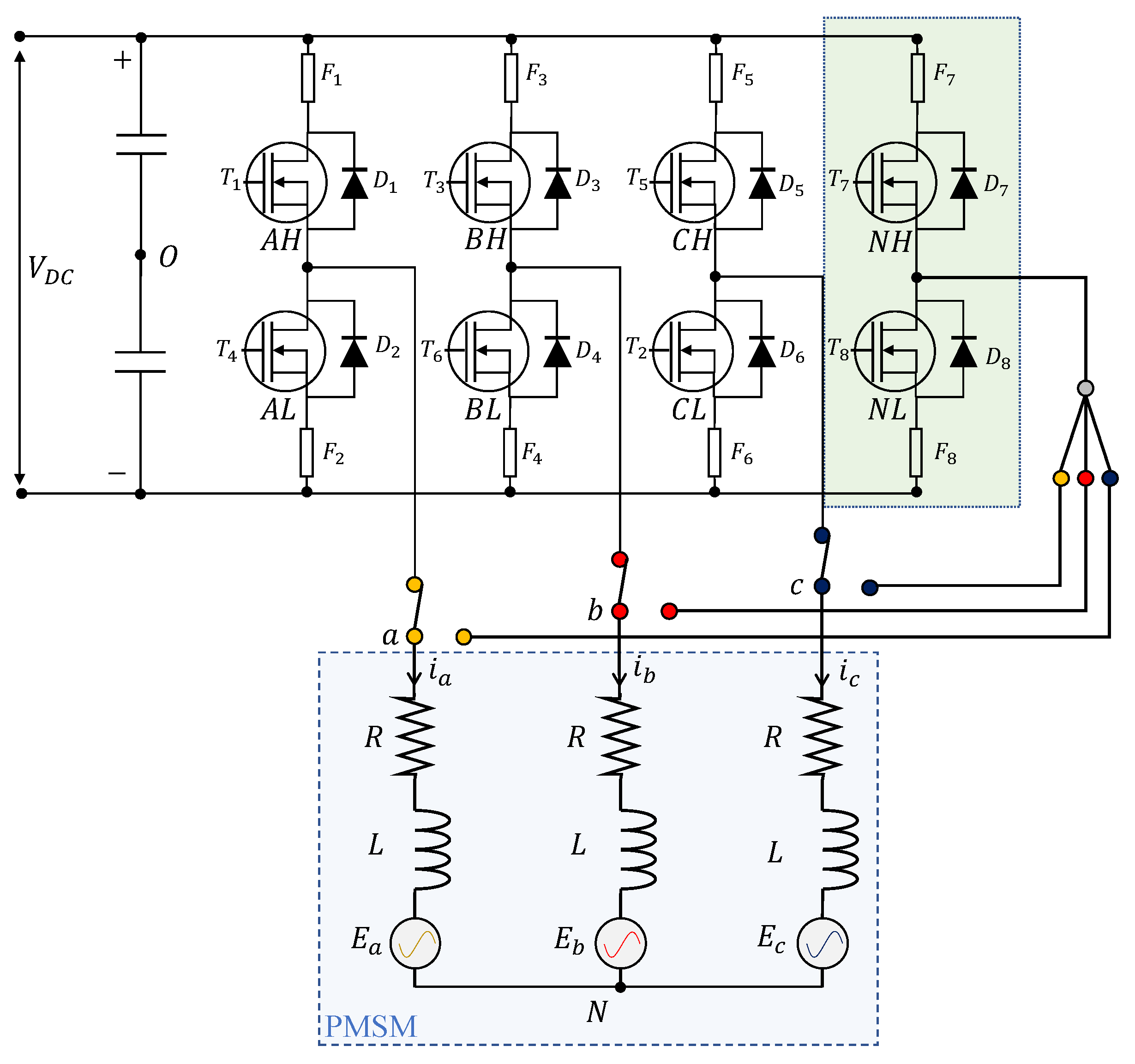
    A four-leg converter;
    Three current sensors, one per motor phase;
    An angular position sensor, measuring the motor angle;
    A power supply unit;
    Two connectors for the data and power supply interfaces, related to the UAV flight control computer and the UAV electrical power system, respectively.
  • An aero-mechanical section, with the following:
  • A twin-blade fixed-pitch propeller [46];
    A mechanical joint coupling the PMSM with the propeller.

    2.4.1. Electronic Control Unit

    In the reference architecture (Figure 4), the control module operates the closed-loop control of the PMSM by implementing two nested loops, on propeller speed and motor currents (via Field-Oriented Control, FOC), respectively. All the regulators implement proportional/integral actions on the tracking error signals, plus anti-windup functions with back-calculation algorithms to compensate for command saturation. In addition, a currents–motion decoupling technique is also applied to direct and quadrature voltage demands, and the PMSM is driven by a Space-Vector PWM (SVPWM) technique.
    The monitoring module executes the FDI algorithms proposed in this work.

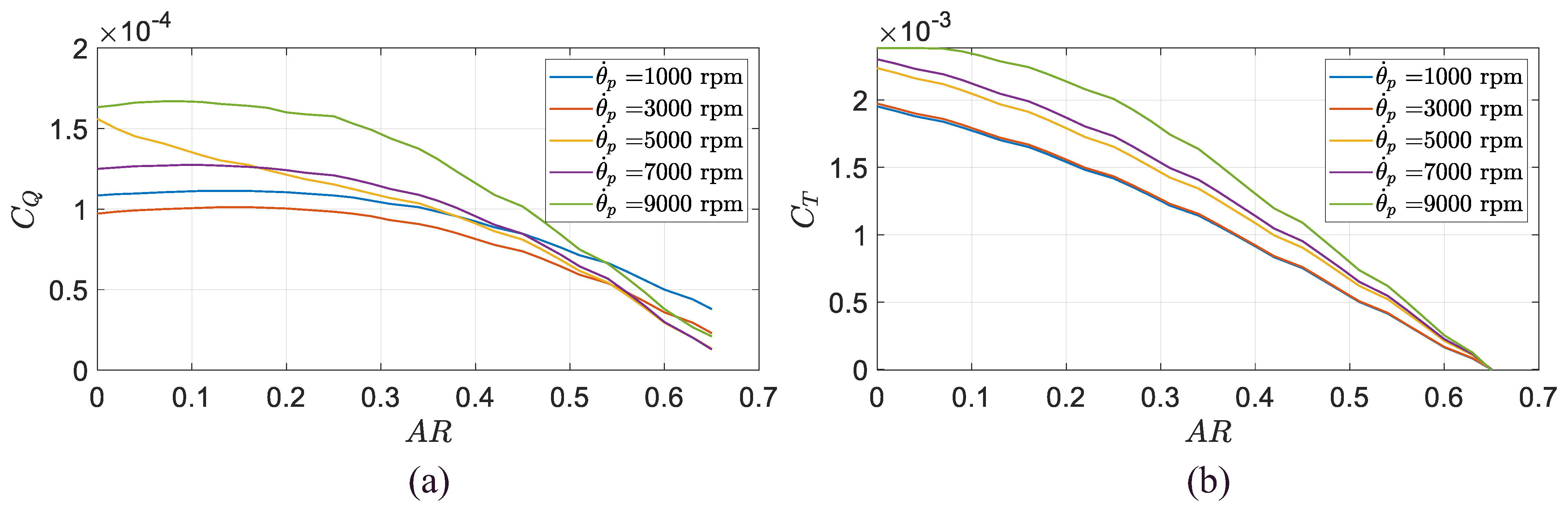
    2.4.2. Aero-Mechanical Modelling

    The dynamics of the aero-mechanical section is schematically depicted in Figure 5 and modelled by the following [15,16]:
    J p θ ¨ p = Q p C g b θ ˙ p θ ˙ m K g b θ p θ m + Q g J m θ ¨ m = Q m + C g b θ ˙ p θ ˙ m + K g b θ p θ m Q p = C Q θ ˙ p , A R ρ D p 5 θ ˙ p 2 T p = C T θ ˙ p , A R ρ D p 4 θ ˙ p 2   A R = 2 π v a / D p θ ˙ p Q m = 3 / 2 k m I q ,
    where θ p is the propeller angle, J p and J m are the propeller and motor inertias, Q p is the aerodynamic torque of the propeller, Q g is the gust-induced torque, Q m is the motor torque, C Q and C T are the nondimensional torque and thrust coefficient of the propeller (Figure 6), A R is the propeller advance ratio, D p is the propeller diameter, ρ is the air density, V a is the UAV forward speed and K g b and C g b are the stiffness and the damping of the mechanical coupling joint. The parameters and data related to the reference propulsion system model are reported in Appendix A.

    3. Results

    The performances of the proposed FDI strategy have been assessed via nonlinear simulation, integrating the propulsion system model with the model of the control/monitoring electronics operating at a 20 kHz sampling rate. All models have been developed in the MATLAB/Simulink/SimScape environment, the numerical solution of which is obtained via a fourth-order Runge–Kutta method, using a 5 × 10⁻⁷ s integration step.
    All simulations are carried out as follows:
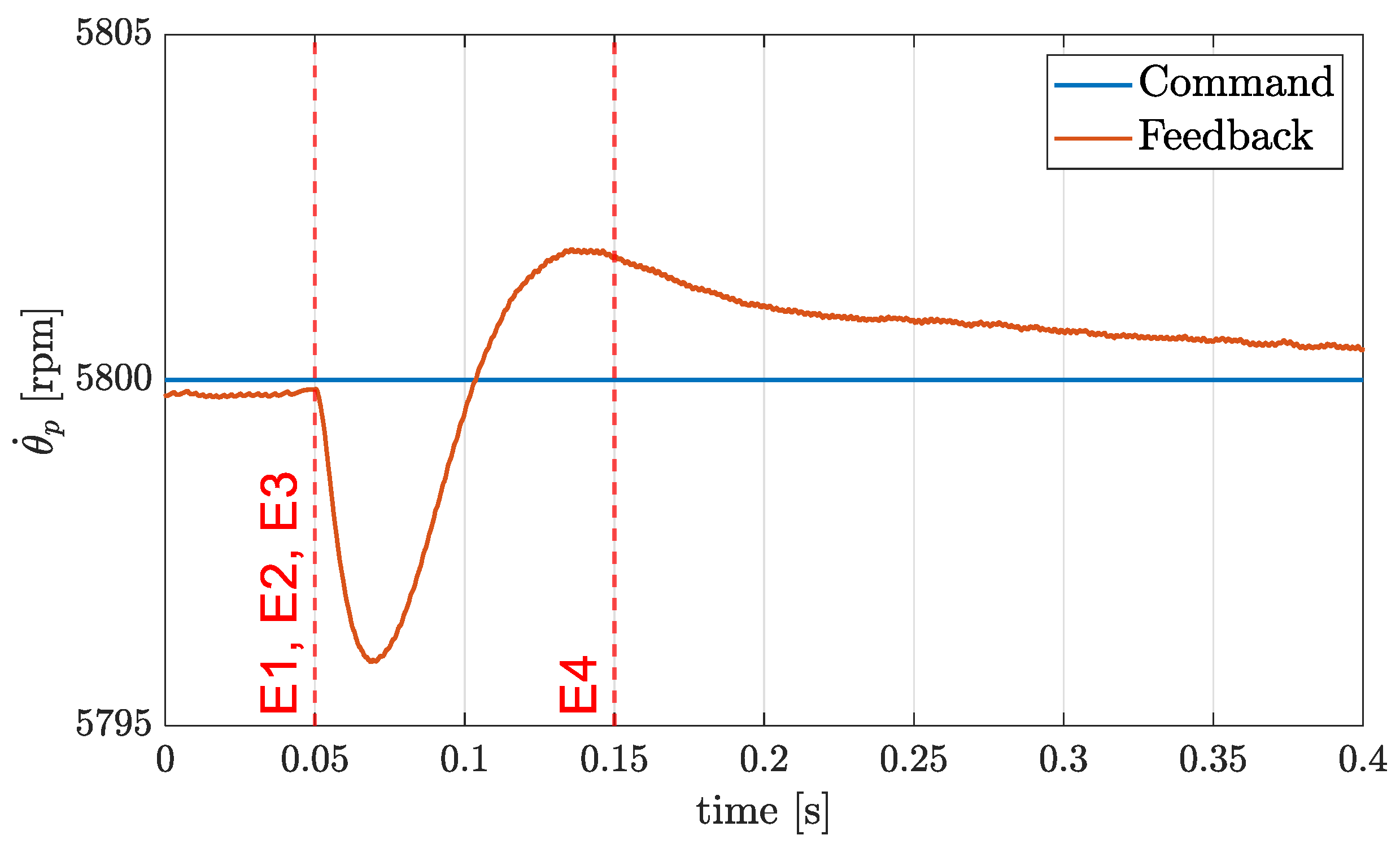
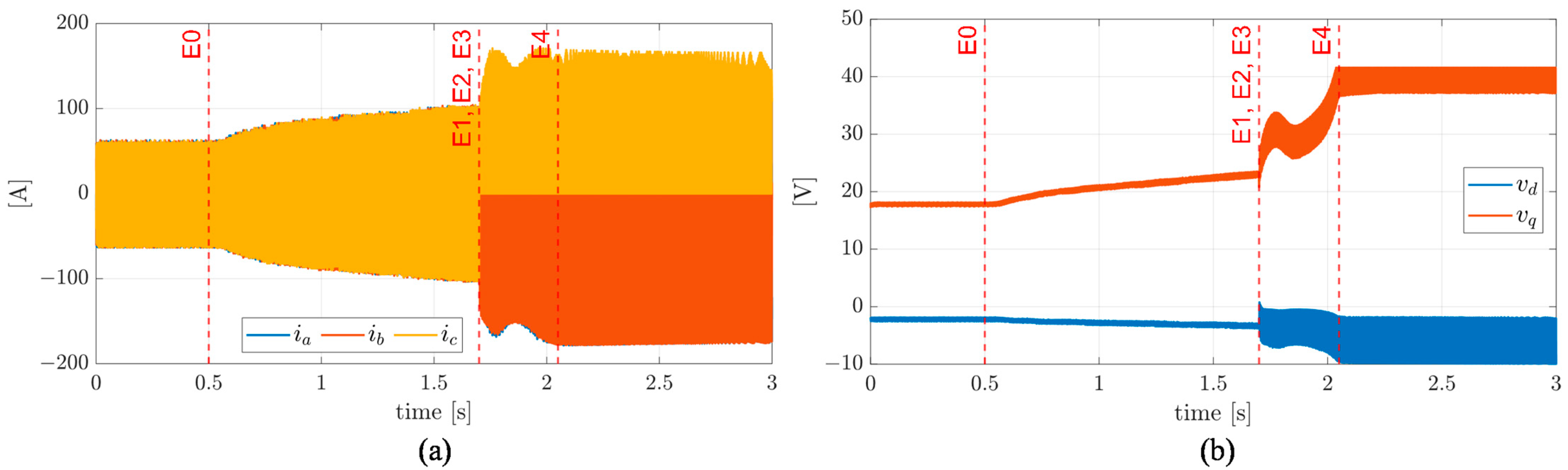
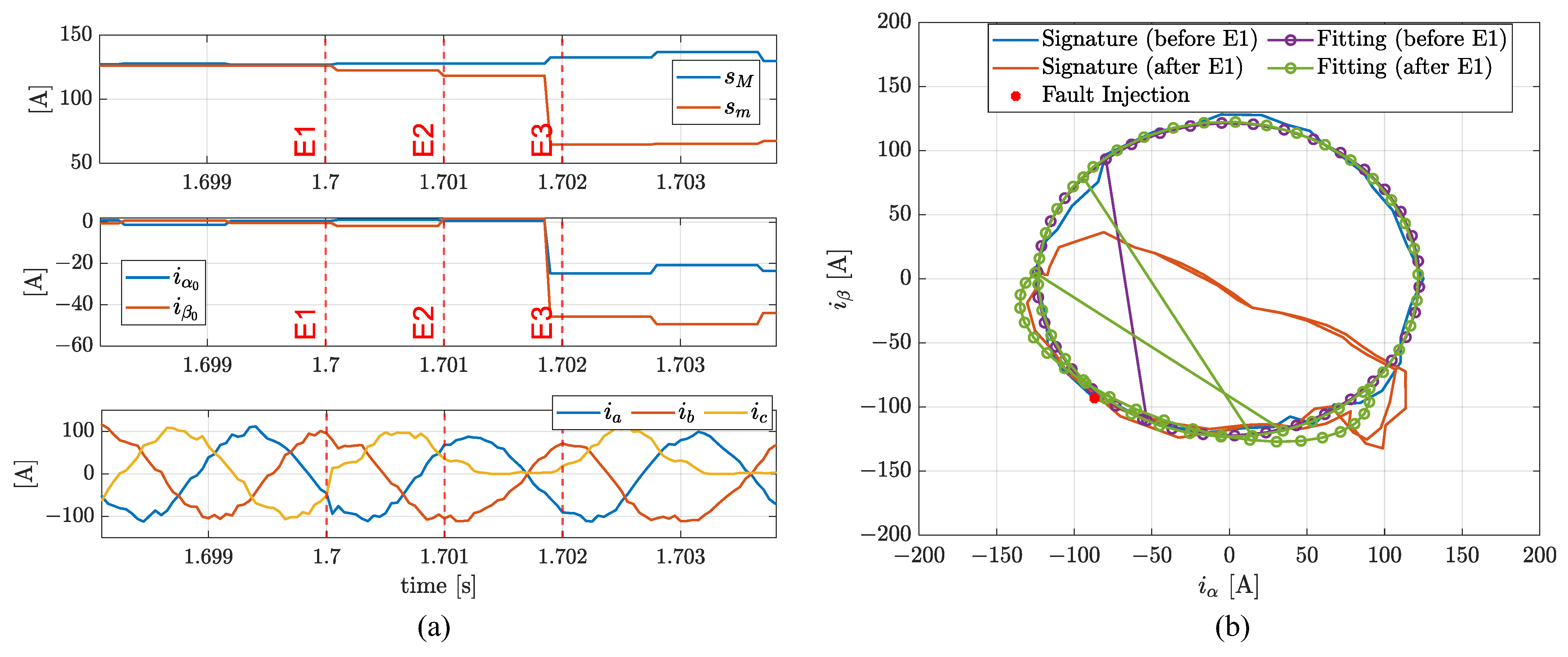
    • Starting (t = 0 s) with the PMSM delivering 1.7 Nm torque at 5800 rpm speed, corresponding to the FEPS operation during the UAV cruise;
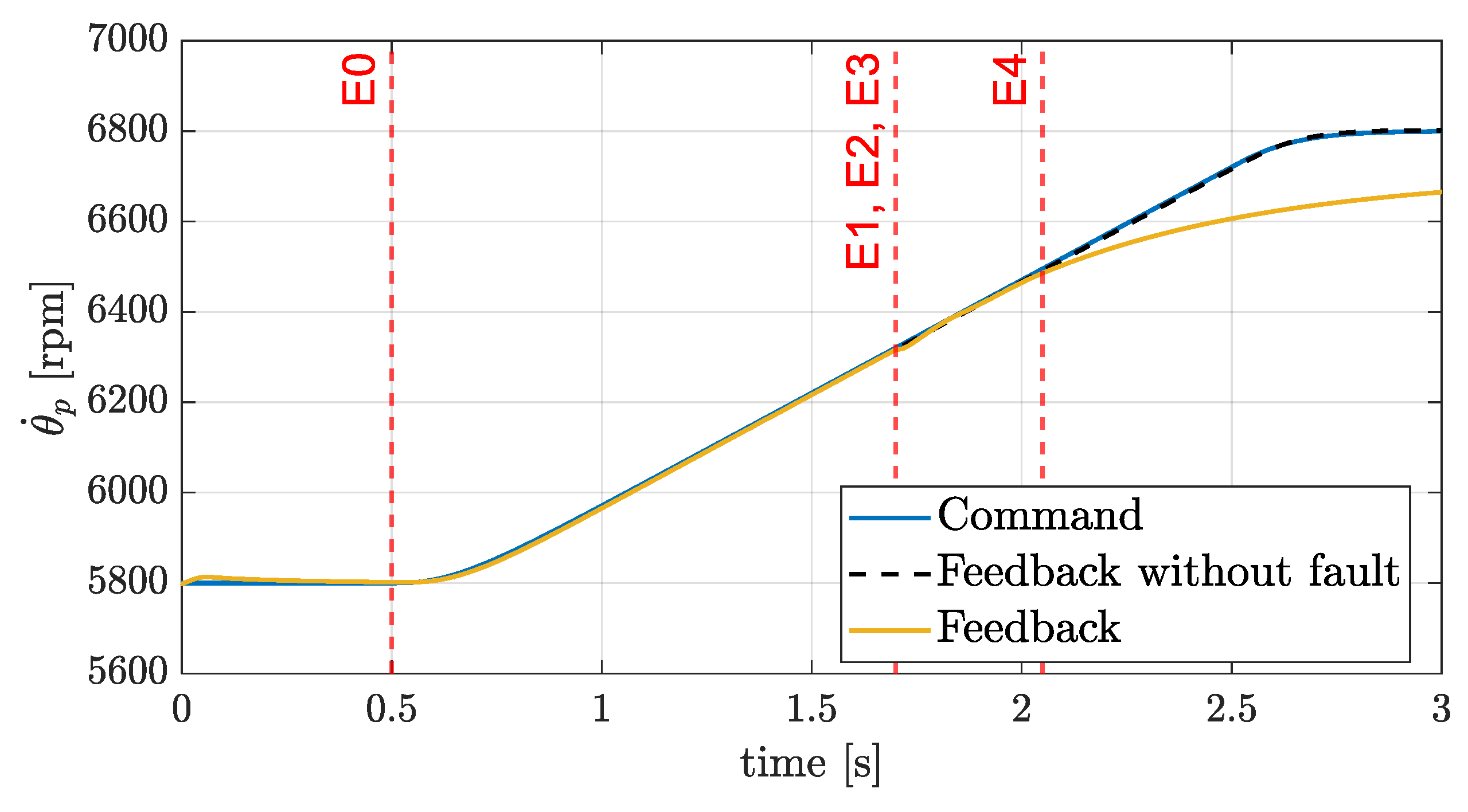
    • Commanding, when applicable, a motor speed increase (Event 0, E0) up to 6800 rpm, corresponding to a UAV transition from cruise to climb;
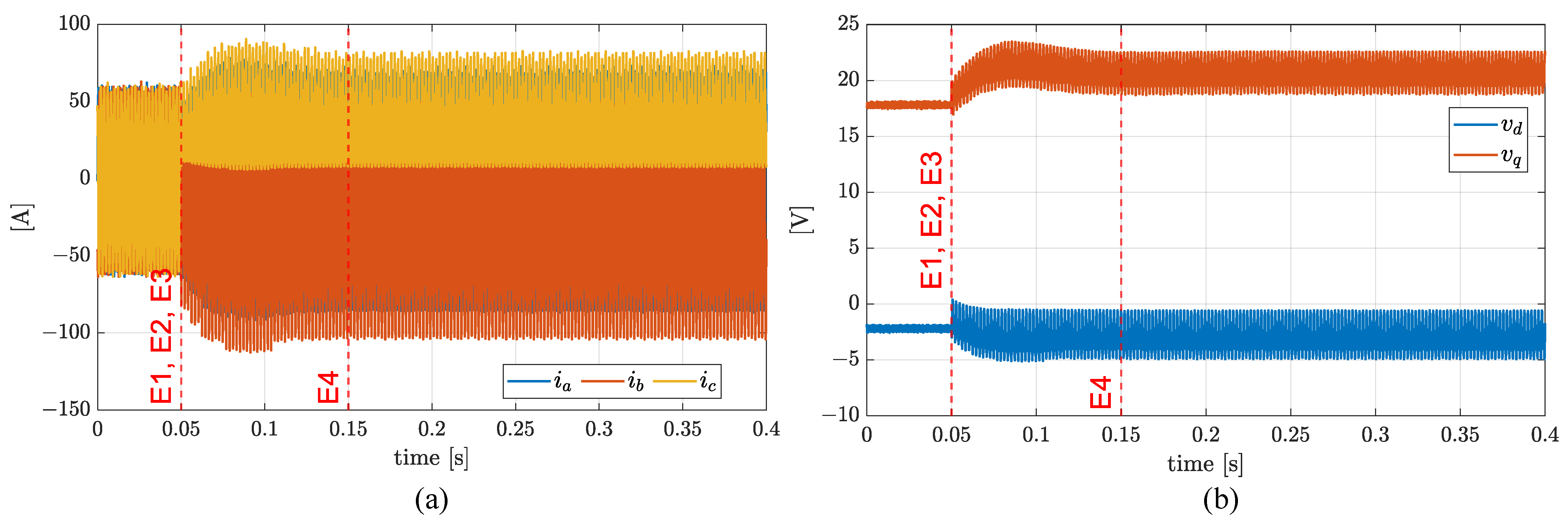
    • Injecting an open-circuit fault in the MOSFET CL (Event 1, E1);
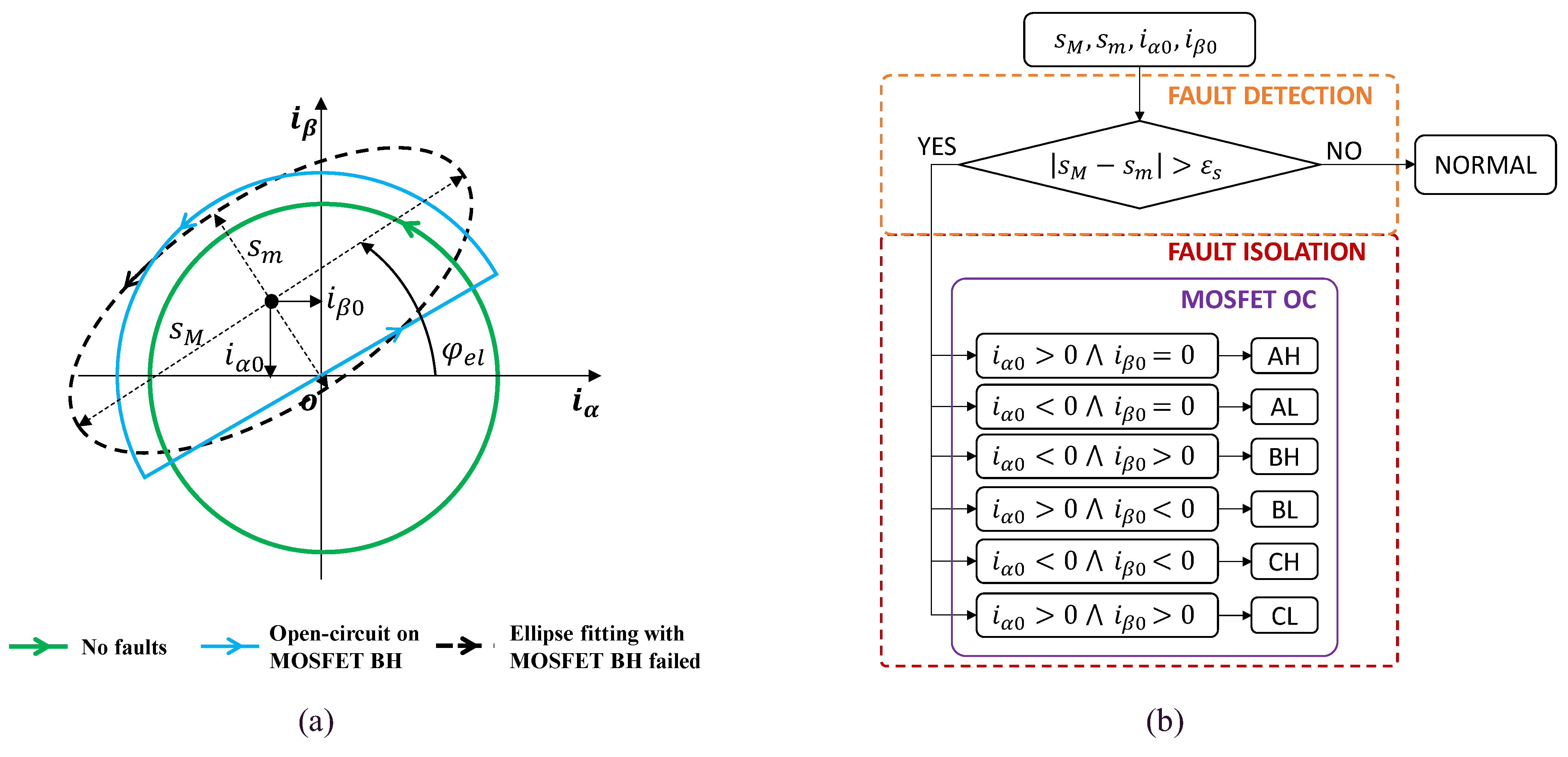
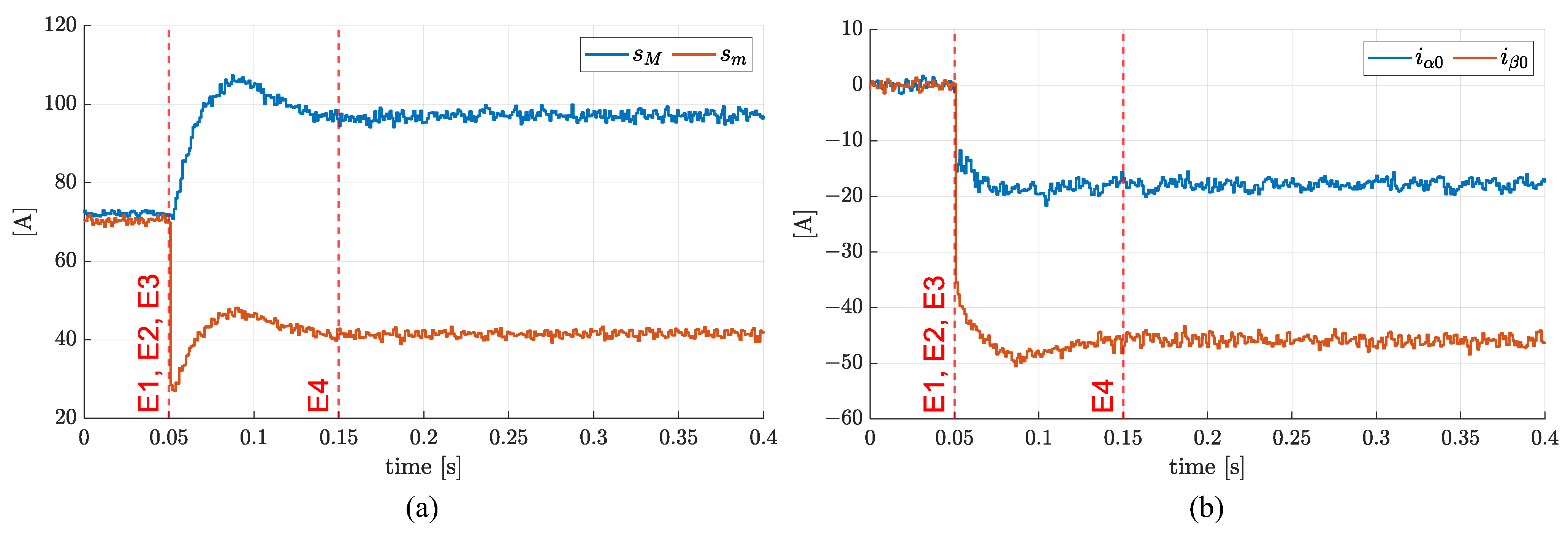
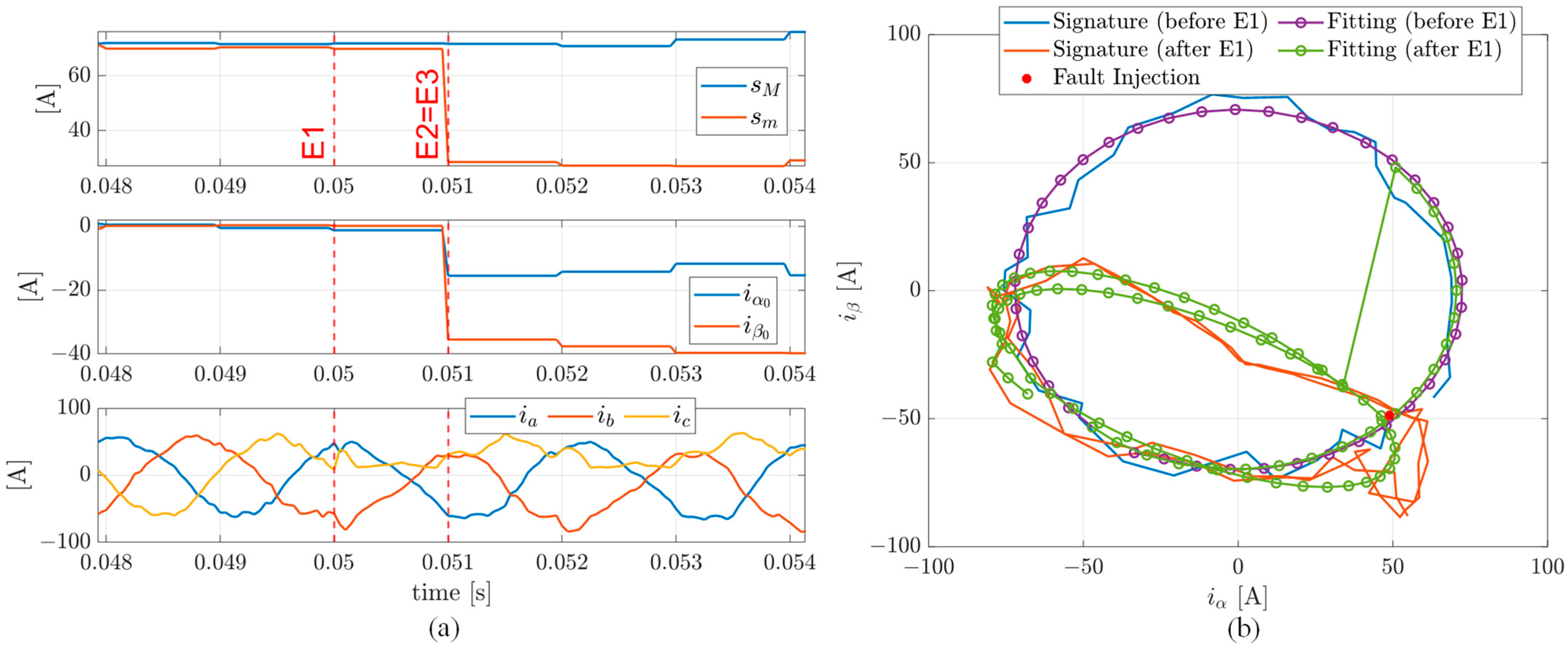
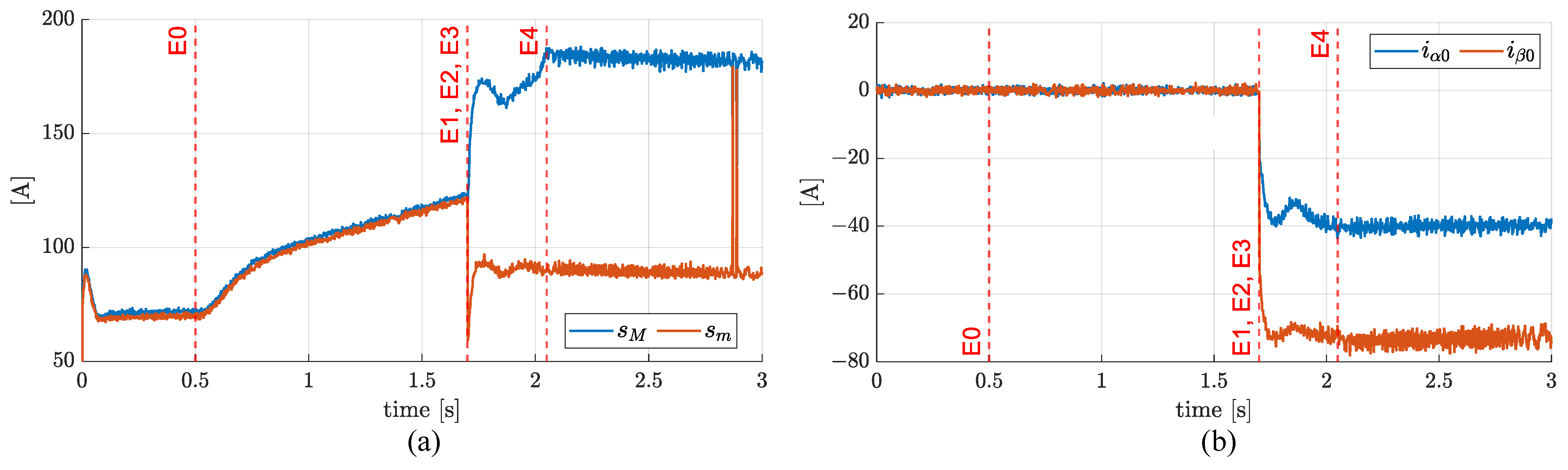
    • Detecting an open-circuit fault (Event 2, E2), when the difference between the lengths of major and minor axes of the reconstructed ellipse is greater than 10% of their mean value ( ε s = 0.05 s M + s m in Figure 3b);
    • Isolating the open-circuit fault (Event 3, E3), when the coordinates of the reconstructed ellipse centre satisfy one of the conditions defined in the FDI logic flow chart in Figure 3b.
    The achievement of a fault regime behaviour (Event 4, E4) is finally defined at the time after which the amplitudes of the demand voltages do not vary more than 10%.

    3.1. Simulation in Cruise Conditions

    In this simulation, the event E0 is not defined and the event E1 occurs at t = 0.05 s. The system response is characterised by imposing that the ellipse fitting in the FDI algorithm is obtained with 40 samples of currents measurements (n = 40, in Section 2.3), with an overlap of 50% of the sample data to reduce the fault latency and to improve the fitting robustness.
    Figure 7 proposes the failure transient (from E1 to E4) in terms of motor speed; the control system effectively rejects the speed deviation from the command, with very limited tracking errors (less than 0.1%). On the other hand, the failure transients in terms of phase currents and demand voltages are more important (see Figure 8). The fault implies a relevant increase in currents amplitudes, which are amplified up to 40% during the transient (from E1 to E4) and by 30% at fault regime (after E4) (see Figure 8a). The fault also impacts on quadrature and direct voltage signals, which exhibit significant oscillations at 1 kHz (about twice the electrical frequency) (see Figure 8b).
    The ellipse parameters obtained by the online fitting technique are then reported in Figure 9. In particular, Figure 9a plots the lengths of the axes of the reconstructed ellipse, while Figure 9b plots the location of the centre of the fitted ellipse in the Clarke plane. To better highlight the algorithm performances in terms of FDI latency (from E1 to E3), Figure 10 reports the results of one electrical period before and two electrical periods after the fault injection. It is worth noting that the difference in axes lengths as well as the coordinates of the ellipse centre (Figure 10a) promptly and contemporarily react to detect and isolate the fault within 1 ms. Consequently, the current phasor trajectory in the Clarke plane (Figure 10b), points out the “D-shape” track caused by the fault, which is isolated within one electrical cycle.

    3.2. Simulation of Transition between Cruise and Climb

    In this second simulation, the event E0 occurs at t = 0.5 s, while the event E1 occurs at t = 1.7 s, when the motor is moving at about 6300 rpm and is accelerating at a rate of 500 rpm/s. The system response is, again, characterised by imposing an online ellipse fitting with 40 samples of current measurements (n = 40, in Section 2.3).
    Figure 11 presents the motor speed failure transient, and also compares the results with the behaviour without faults. In this flight condition, the propulsion system is not able to reach the command; the resistant torque developed by the propeller, roughly depending on the square of motor speed, is actually too high, and the UAV is not able to perform the climb at the required rate. Figure 12 helps in interpreting this behaviour; the current amplitudes dramatically increase (Figure 12a) and a quadrature voltage saturation occurs (E4 in Figure 12b).
    The fitting ellipse parameters for this simulation are reported in Figure 13 and with more detail on failure transients in Figure 14 (the results refer to one electrical period before and two electrical periods after the fault injection). The detection of the fault (E2) again occurs within 1 ms, but the fault isolation (E3) is delayed, being accomplished 2 ms after the fault (see Figure 14a). It is worth noting from Figure 14b that, even in this case, the algorithm again performs the FDI within one electrical cycle.

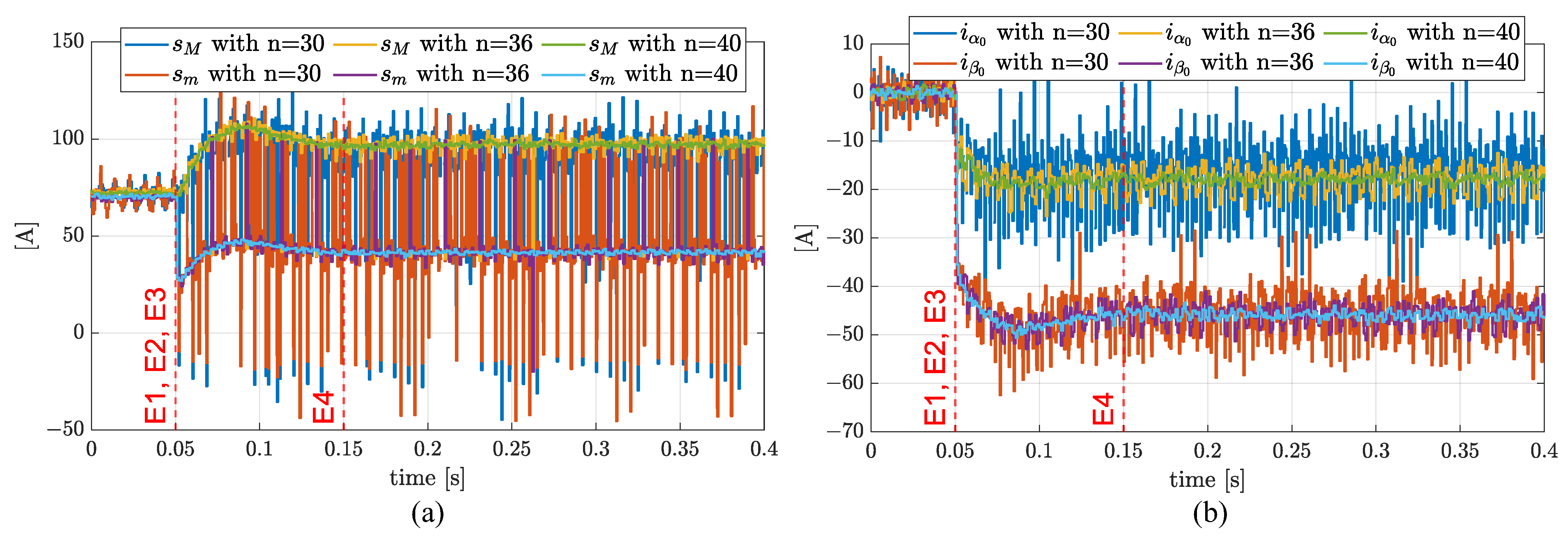
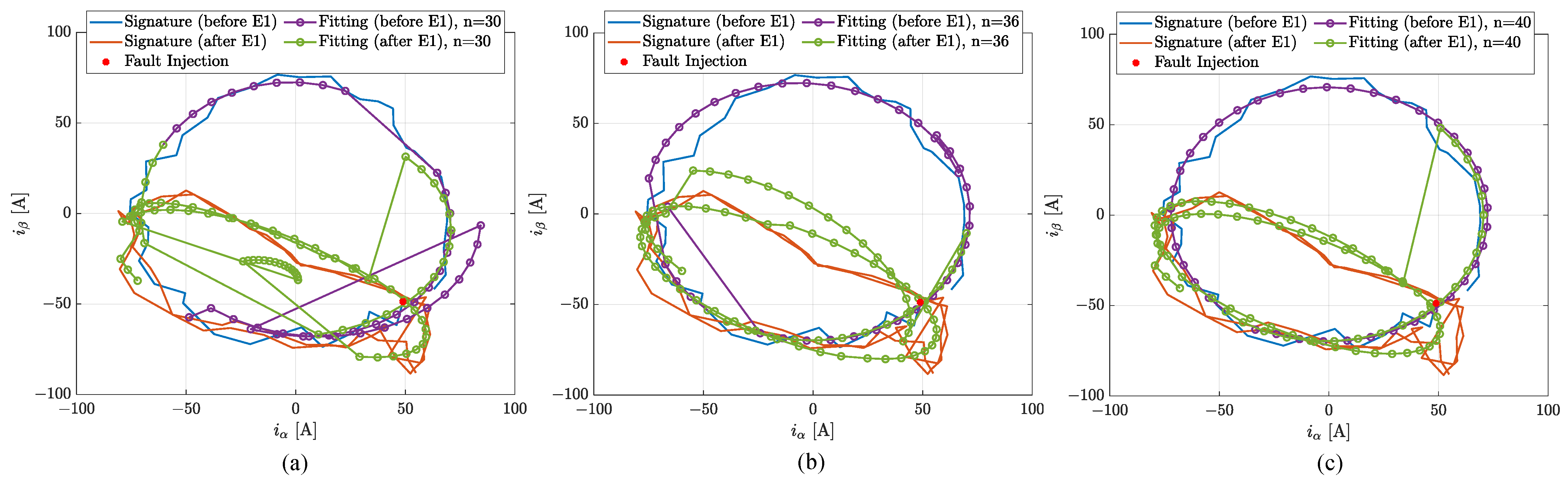
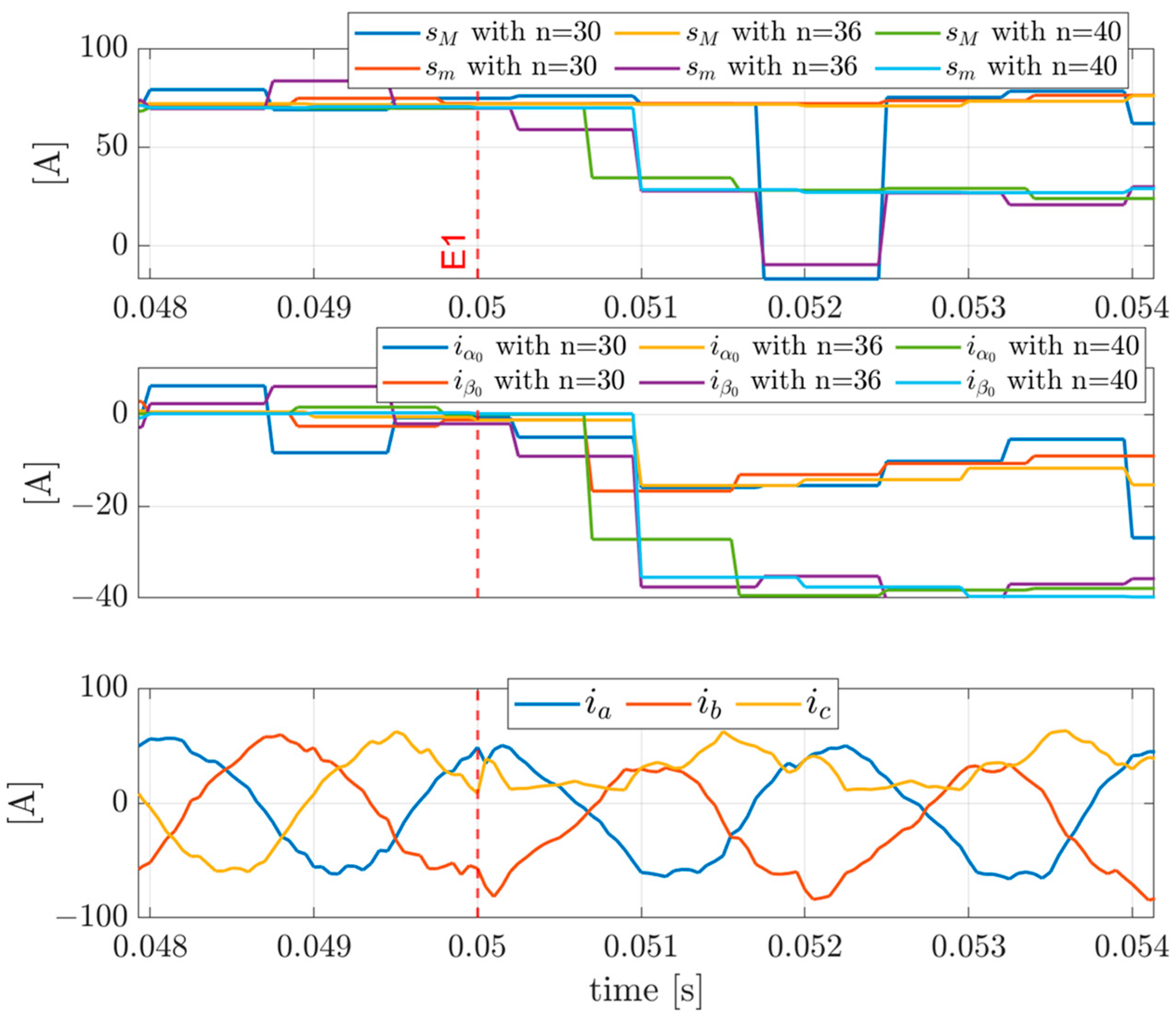
    3.3. Impact of Number of Samples on the Algorithm Performances

    Since the FDI algorithm relies on the online solution of a fitting problem, its performances strongly depend on the number of measurements used for the process. The results reported in this section aim to document the impact of the number of samples used by the algorithm, simulating the failure transient as per Section 3.1, but imposing 30, 36 and 40 samples for the ellipse fitting.
    The axes of the fitted ellipse are shown in Figure 15a, while the coordinates of the ellipse centre are reported in Figure 15b. The FDI performances are not satisfactory with n = 30, while they significantly improve for n = 36, with results in them being essentially in line with those at n = 40. The sensitivity to the number of samples is also outlined by Figure 16, where the current phasor trajectories and the ellipse fittings are shown for a time window related to one electrical period before and two electrical periods after the fault injection. With reference to the same time window, the diagnostic indexes and the current phases are shown in Figure 17. Since the reduction in the number of samples clearly implies faster detection, values from 35 to 40 have been considered suitable for the reference application.

    4. Discussion

    The advantages and drawbacks of the proposed current-based method based on the current-signature technique, with respect to other methods from the literature, are summarised in Table 3. The comparison highlights that the developed method is competitive in terms of both isolation time (FDI of a power switch fault is accomplished within one electrical period) and the number of samples per electrical period. In addition, the method has been demonstrated to be suitable for high-speed applications, and it is applicable to the FDI of different types of PMSM faults, as open-phases or inter-turn short circuits. Another notable aspect is the implementation simplicity; the method actually operates linear algebra operations, without the need for calculating the time derivatives of signals. As its main limitation, the technique relies on the assumption that the load applied to the motor (i.e., the amplitudes of the current phasor) is constant within an electrical cycle. However, this hypothesis is not stringent for applications (as for UAV propulsion) where the loading dynamics evolve on time scales that are much larger than the motor electrical period.
    In terms of future perspectives, research will be focused on the generalisation of the FDI technique to major electric and electronic faults in PMSMs. This activity will consider the integration/adaptation of algorithms related to inter-turn short-circuits with the one described in this work, as well as with upcoming developments dedicated to the FDI of open-phase faults.

    5. Conclusions

    The results demonstrate that the proposed FDI algorithm, based on online ellipse fitting to reconstruct the trajectory of the current phasor in the Clarke plane in three-phase PMSMs, succeeds in detecting and isolating open circuits on power switch converters with extremely small latencies (from the injection to the detection/isolation of the fault, the motor rotates less than 180° in an electrical cycle). Simulation analyses also highlighted the robustness of the algorithm against transient dynamics, due to the transition of the phase connection from a failed to an active switch.

    Author Contributions

    Conceptualisation, methodology, validation, investigation, A.S. and G.D.R.; software, data curation, writing—original draft preparation, A.S.; writing—review and editing, formal analysis, resources, visualisation, supervision, project administration, funding acquisition, G.D.R. All authors have read and agreed to the published version of the manuscript.

    Funding

    This research received no external funding.

    Data Availability Statement

    Data is unavailable due to privacy.

    Conflicts of Interest

    The authors declare no conflicts of interest.

    Appendix A

    This section reports the parameters of the propulsion system model (Table A1).
    Table A1. FEPS model parameters.
    Table A1. FEPS model parameters.
    DefinitionSymbolValueUnit
    Stator phase resistance R 0.025Ω
    Stator phase inductance L 2 × 10⁻⁵H
    Pole pairs number n d 5-
    Motor speed constant k m 0.0152V/(rad/s)
    Voltage supply V D C 48V
    Rotor inertia J m 2.2 × 10⁻²kg·m2
    Propeller diameter D p 0.5588m
    Propeller inertia J p 1.186 × 10⁻³kg·m2
    Coupling joint stiffness K g b 1.598 × 10³Nm/rad
    Coupling joint damping C g b 0.2545Nm/(rad/s)
    Rated power P e m m a x 3200W
    Sampling frequency f s 20kHz

    References

    1. Chan, C.C. The State of the Art of Electric and Hybrid Vehicles. Proc. IEEE 2002, 90, 247–275. [Google Scholar] [CrossRef]
    2. Zhang, B.; Song, Z.; Zhao, F.; Liu, C. Overview of Propulsion Systems for Unmanned Aerial Vehicles. Energies 2022, 15, 455. [Google Scholar] [CrossRef]
    3. Suti, A.; Di Rito, G.; Galatolo, R. Climbing Performance Enhancement of Small Fixed-Wing UAVs via Hybrid Electric Propulsion. In Proceedings of the 2021 IEEE Workshop on Electrical Machines Design, Control and Diagnosis (WEMDCD), Modena, Italy, 8–9 April 2021; pp. 305–310. [Google Scholar]
    4. Nandi, S.; Toliyat, H.A.; Li, X. Condition Monitoring and Fault Diagnosis of Electrical Motors—A Review. IEEE Trans. Energy Convers. 2005, 20, 719–729. [Google Scholar] [CrossRef]
    5. Suti, A.; Di Rito, G.; Galatolo, R. Fault-Tolerant Control of a Three-Phase Permanent Magnet Synchronous Motor for Lightweight UAV Propellers via Central Point Drive. Actuators 2021, 10, 253. [Google Scholar] [CrossRef]
    6. STANAG 4671—Standardization Agreement—Unmanned Aerial Vehicles Systems Airworthiness Requirements (USAR); NATO Standardization Agency: Brussels, Belgium, 2009.
    7. Zhang, Y.; Liu, G.; Zhao, W.; Zhou, H.; Chen, Q.; Wei, M. Online Diagnosis of Slight Interturn Short-Circuit Fault for a Low-Speed Permanent Magnet Synchronous Motor. IEEE Trans. Transp. Electrif. 2021, 7, 104–113. [Google Scholar] [CrossRef]
    8. Ramoul, J.; Watthewaduge, G.; Callegaro, A.D.; Nahid-Mobarakeh, B.; Baronian, A.; Emadi, A. Analysis of Open Phase and Phase-to-Phase Short Circuit Fault of PMSM for Electrical Propulsion in an EVTOL. In Proceedings of the IECON 2021—47th Annual Conference of the IEEE Industrial Electronics Society, Toronto, ON, Canada, 13–16 October 2021; pp. 1–6. [Google Scholar]
    9. Suti, A.; Di Rito, G.; Galatolo, R. Fault-Tolerant Control of a Dual-Stator PMSM for the Full-Electric Propulsion of a Lightweight Fixed-Wing UAV. Aerospace 2022, 9, 337. [Google Scholar] [CrossRef]
    10. Kontarcek, A.; Bajec, P.; Nemec, M.; Ambrozic, V.; Nedeljkovic, D. Cost-Effective Three-Phase PMSM Drive Tolerant to Open-Phase Fault. IEEE Trans. Ind. Electron. 2015, 62, 6708–6718. [Google Scholar] [CrossRef]
    11. Wenping, C.; Mecrow, B.C.; Atkinson, G.J.; Bennett, J.W.; Atkinson, D.J. Overview of Electric Motor Technologies Used for More Electric Aircraft (MEA). IEEE Trans. Ind. Electron. 2012, 59, 3523–3531. [Google Scholar] [CrossRef]
    12. Lee, K.-B.; Choi, U.-M. Faults and Diagnosis Systems in Power Converters. In Advanced and Intelligent Control in Power Electronics and Drives; Springer: Cham, Switzerland, 2014; pp. 143–178. [Google Scholar]
    13. Orlowska-Kowalska, T.; Wolkiewicz, M.; Pietrzak, P.; Skowron, M.; Ewert, P.; Tarchala, G.; Krzysztofiak, M.; Kowalski, C.T. Fault Diagnosis and Fault-Tolerant Control of PMSM Drives–State of the Art and Future Challenges. IEEE Access 2022, 10, 59979–60024. [Google Scholar] [CrossRef]
    14. Huang, J.; Zhang, Z.; Jiang, W. Fault-Tolerant Control of Open-Circuit Fault for Permanent Magnet Starter/Generator. In Proceedings of the 2018 21st International Conference on Electrical Machines and Systems (ICEMS), Jeju, Republic of Korea, 7–10 October 2018; pp. 5–10. [Google Scholar]
    15. Suti, A.; Di Rito, G.; Mattei, G. Condition Monitoring of the Torque Imbalance in a Dual-Stator Permanent Magnet Synchronous Motor for the Propulsion of a Lightweight Fixed-Wing UAV. Drones 2023, 7, 618. [Google Scholar] [CrossRef]
    16. Mazzoleni, M.; Di Rito, G.; Previdi, F. Electro-Mechanical Actuators for the More Electric Aircraft; Springer: Cham, Switzerland, 2021; ISBN 978-3-030-61798-1. [Google Scholar]
    17. Beltrao de Rossiter Correa, M.; Brandao Jacobina, C.; Cabral da Silva, E.R.; Nogueira Lima, A.M. An Induction Motor Drive System with Improved Fault Tolerance. IEEE Trans. Ind. Appl. 2001, 37, 873–879. [Google Scholar] [CrossRef]
    18. Ribeiro, R.L.A.; Jacobina, C.B.; Lima, A.M.N.; da Silva, E.R.C. A Strategy for Improving Reliability of Motor Drive Systems Using a Four-Leg Three-Phase Converter. In Proceedings of the APEC 2001. Sixteenth Annual IEEE Applied Power Electronics Conference and Exposition (Cat. No.01CH37181), Anaheim, CA, USA, 4–8 March 2001; pp. 385–391. [Google Scholar]
    19. Li, W.; Tang, H.; Luo, S.; Yan, X.; Wu, Z. Comparative Analysis of the Operating Performance, Magnetic Field, and Temperature Rise of the Three-phase Permanent Magnet Synchronous Motor with or without Fault-tolerant Control under Single-phase Open-circuit Fault. IET Electr. Power Appl. 2021, 15, 861–872. [Google Scholar] [CrossRef]
    20. Liang, J.; Zhang, K.; Al-Durra, A.; Muyeen, S.M.; Zhou, D. A State-of-the-Art Review on Wind Power Converter Fault Diagnosis. Energy Rep. 2022, 8, 5341–5369. [Google Scholar] [CrossRef]
    21. Naseri, F.; Schaltz, E.; Lu, K.; Farjah, E. Real-time Open-switch Fault Diagnosis in Automotive Permanent Magnet Synchronous Motor Drives Based on Kalman Filter. IET Power Electron. 2020, 13, 2450–2460. [Google Scholar] [CrossRef]
    22. Salehifar, M.; Salehi Arashloo, R.; Moreno-Eguilaz, M.; Sala, V.; Romeral, L. Observer-based Open Transistor Fault Diagnosis and Fault-tolerant Control of Five-phase Permanent Magnet Motor Drive for Application in Electric Vehicles. IET Power Electron. 2015, 8, 76–87. [Google Scholar] [CrossRef]
    23. Zhou, X.; Sun, J.; Cui, P.; Lu, Y.; Lu, M.; Yu, Y. A Fast and Robust Open-Switch Fault Diagnosis Method for Variable-Speed PMSM System. IEEE Trans. Power Electron. 2021, 36, 2598–2610. [Google Scholar] [CrossRef]
    24. Kiselev, A.; Catuogno, G.R.; Kuznietsov, A.; Leidhold, R. Finite-Control-Set MPC for Open-Phase Fault-Tolerant Control of PM Synchronous Motor Drives. IEEE Trans. Ind. Electron. 2020, 67, 4444–4452. [Google Scholar] [CrossRef]
    25. Huang, W.; Du, J.; Hua, W.; Lu, W.; Bi, K.; Zhu, Y.; Fan, Q. Current-Based Open-Circuit Fault Diagnosis for PMSM Drives With Model Predictive Control. IEEE Trans. Power Electron. 2021, 36, 10695–10704. [Google Scholar] [CrossRef]
    26. Huang, W.; Du, J.; Hua, W.; Fan, Q. An Open-Circuit Fault Diagnosis Method for PMSM Drives Using Symmetrical and DC Components. Chin. J. Electr. Eng. 2021, 7, 124–135. [Google Scholar] [CrossRef]
    27. Estima, J.O.; Marques Cardoso, A.J. A New Algorithm for Real-Time Multiple Open-Circuit Fault Diagnosis in Voltage-Fed PWM Motor Drives by the Reference Current Errors. IEEE Trans. Ind. Electron. 2013, 60, 3496–3505. [Google Scholar] [CrossRef]
    28. Gmati, B.; Jlassi, I.; Khojet El Khil, S.; Marques Cardoso, A.J. Open-switch Fault Diagnosis in Voltage Source Inverters of PMSM Drives Using Predictive Current Errors and Fuzzy Logic Approach. IET Power Electron. 2021, 14, 1059–1072. [Google Scholar] [CrossRef]
    29. Li, P.; Xu, X.; Yang, S.; Jiang, X. Open Circuit Fault Diagnosis Strategy of PMSM Drive System Based on Grey Prediction Theory for Industrial Robot. Energy Rep. 2023, 9, 313–320. [Google Scholar] [CrossRef]
    30. Zhang, Y. Current Behavior-Based Open-Switch Fault on-Line Diagnosis of Inverters in PMSM Drive Systems. Measurement 2022, 202, 111810. [Google Scholar] [CrossRef]
    31. Manikandan, R.; Singh, R.R. Open Switch Fault Diagnosis of VSI-Fed PMSM Drive Using MPC Cost Function and Burg Algorithm. In Proceedings of the 2022 IEEE 1st Industrial Electronics Society Annual On-Line Conference (ONCON), Kharagpur, India, 9–11 December 2022; pp. 1–6. [Google Scholar]
    32. Im, W.-S.; Kim, J.-S.; Kim, J.-M.; Lee, D.-C.; Lee, K.-B. Diagnosis Methods for IGBT Open Switch Fault Applied to 3-Phase AC/DC PWM Converter. J. Power Electron. 2012, 12, 120–127. [Google Scholar] [CrossRef]
    33. Peuget, R.; Courtine, S.; Rognon, J.-P. Fault Detection and Isolation on a PWM Inverter by Knowledge-Based Model. IEEE Trans. Ind. Appl. 1998, 34, 1318–1326. [Google Scholar] [CrossRef]
    34. Kral, C.; Kafka, K. Power Electronics Monitoring for a Controlled Voltage Source Inverter Drive with Induction Machines. In Proceedings of the 2000 IEEE 31st Annual Power Electronics Specialists Conference. Conference Proceedings (Cat. No.00CH37018), Galway, Ireland, 23 June 2000; pp. 213–217. [Google Scholar]
    35. Wu, X.; Tian, R.; Cheng, S.; Chen, T.; Tong, L. A Nonintrusive Diagnostic Method for Open-Circuit Faults of Locomotive Inverters Based on Output Current Trajectory. IEEE Trans. Power Electron. 2018, 33, 4328–4341. [Google Scholar] [CrossRef]
    36. Trabelsi, M.; Boussak, M.; Gossa, M. Multiple IGBTs Open Circuit Faults Diagnosis in Voltage Source Inverter Fed Induction Motor Using Modified Slope Method. In Proceedings of the The XIX International Conference on Electrical Machines—ICEM 2010, Rome, Italy, 6–8 September 2010; pp. 1–6. [Google Scholar]
    37. Sun, X.; Diao, N.; Song, C.; Qiu, Y.; Zhao, X. An Open-Circuit Fault Diagnosis Method Based on Adjacent Trend Line Relationship of Current Vector Trajectory for Motor Drive Inverter. Machines 2023, 11, 928. [Google Scholar] [CrossRef]
    38. Sobanski, P.; Orlowska-Kowalska, T. Open Switch Fault Diagnosis Methods for an AC/DC Line-Side Converter. In Proceedings of the 2017 IEEE International Conference on Industrial Technology (ICIT), Toronto, ON, Canada, 22–25 March 2017; pp. 1580–1585. [Google Scholar]
    39. Freire, N.M.A.; Estima, J.O.; Cardoso, A.J.M. A Voltage-Based Approach Without Extra Hardware for Open-Circuit Fault Diagnosis in Closed-Loop PWM AC Regenerative Drives. IEEE Trans. Ind. Electron. 2014, 61, 4960–4970. [Google Scholar] [CrossRef]
    40. Choi, C.; Lee, W. Design and Evaluation of Voltage Measurement-Based Sectoral Diagnosis Method for Inverter Open Switch Faults of Permanent Magnet Synchronous Motor Drives. IET Electr. Power Appl. 2012, 6, 526. [Google Scholar] [CrossRef]
    41. Wang, B.; Feng, X.; Wang, R. Open-Circuit Fault Diagnosis for Permanent Magnet Synchronous Motor Drives Based on Voltage Residual Analysis. Energies 2023, 16, 5722. [Google Scholar] [CrossRef]
    42. Suti, A.; Di Rito, G.; Galatolo, R. Novel Approach to Fault-Tolerant Control of Inter-Turn Short Circuits in Permanent Magnet Synchronous Motors for UAV Propellers. Aerospace 2022, 9, 401. [Google Scholar] [CrossRef]
    43. Fitzgibbon, A.W.; Pilu, M.; Fisher, R.B. Direct Least Squares Fitting of Ellipses. In Proceedings of the 13th International Conference on Pattern Recognition, Vienna, Austria, 25–29 August 1996; pp. 253–257. [Google Scholar]
    44. Halir, R.; Flusser, J. Numerically stable direct least squares fitting of ellipses. In Proceedings of the 6th International Conference in Central Europe on Computer Graphics and Visualization, Plzen-Bory, Czech Republic, 9–13 February 1998. [Google Scholar]
    45. Weisstein, E.W. “Ellipse”, MathWorld—A Wolfram Web Resource. Available online: https://mathworld.wolfram.com/Ellipse.html (accessed on 15 November 2023).
    46. APC Propellers TECHNICAL INFO. Available online: https://www.apcprop.com/technical-information/performance-data/ (accessed on 10 May 2023).
    Figure 1. Four-leg converter driving a three-phase PMSM with access to the central point.
    Figure 1. Four-leg converter driving a three-phase PMSM with access to the central point.
    Actuators 13 00025 g001
    Figure 2. Current phasor trajectory in the Clarke plane in normal conditions and with open-circuit faults: (a) phase fault; (b) low-side power switch fault; (c) high-side power switch fault.
    Figure 2. Current phasor trajectory in the Clarke plane in normal conditions and with open-circuit faults: (a) phase fault; (b) low-side power switch fault; (c) high-side power switch fault.
    Actuators 13 00025 g002
    Figure 3. Fault diagnosis conceptualisation: (a) ellipse fitting for the current phasor trajectory in the Clarke plane in case of open-circuit fault on MOSFET BH; (b) flow chart of the FDI logic.
    Figure 3. Fault diagnosis conceptualisation: (a) ellipse fitting for the current phasor trajectory in the Clarke plane in case of open-circuit fault on MOSFET BH; (b) flow chart of the FDI logic.
    Actuators 13 00025 g003
    Figure 4. Architecture of the electronic control unit of the reference FEPS (FCC: Flight Control Computer; EPGDS: Electrical Power Generation and Distribution System; CBCS FDI: Current-Based/Current-Signature FDI).
    Figure 4. Architecture of the electronic control unit of the reference FEPS (FCC: Flight Control Computer; EPGDS: Electrical Power Generation and Distribution System; CBCS FDI: Current-Based/Current-Signature FDI).
    Actuators 13 00025 g004
    Figure 5. FEPS modelling: (a) aero-mechanical schematics; (b) electrical schematics ( n d = 1 ).
    Figure 5. FEPS modelling: (a) aero-mechanical schematics; (b) electrical schematics ( n d = 1 ).
    Actuators 13 00025 g005
    Figure 6. Torque coefficient (a) and thrust coefficient (b) as functions of propeller speed and advance ratio for the APC 18 × 22E propeller.
    Figure 6. Torque coefficient (a) and thrust coefficient (b) as functions of propeller speed and advance ratio for the APC 18 × 22E propeller.
    Actuators 13 00025 g006
    Figure 7. Failure transient due to an open-circuit of MOSFET CL (low-side, phase C) during cruise: motor speed.
    Figure 7. Failure transient due to an open-circuit of MOSFET CL (low-side, phase C) during cruise: motor speed.
    Actuators 13 00025 g007
    Figure 8. Failure transient due to an open-circuit of MOSFET CL (low-side, phase C) during cruise: (a) phase currents; (b) direct and quadrature voltages.
    Figure 8. Failure transient due to an open-circuit of MOSFET CL (low-side, phase C) during cruise: (a) phase currents; (b) direct and quadrature voltages.
    Actuators 13 00025 g008
    Figure 9. Failure transient due to an open-circuit of MOSFET CL (low-side, phase C) during cruise: (a) axes lengths of the fitted ellipse; (b) location of the centre of the fitted ellipse.
    Figure 9. Failure transient due to an open-circuit of MOSFET CL (low-side, phase C) during cruise: (a) axes lengths of the fitted ellipse; (b) location of the centre of the fitted ellipse.
    Actuators 13 00025 g009
    Figure 10. Failure transient due to an open-circuit of MOSFET CL (low-side, phase C) during cruise, with results obtained one electrical period before and two electrical periods after the fault injection: (a) axes lengths of the fitted ellipse (top), location of the centre of the fitted ellipse (middle), phase currents (bottom); (b) current phasor trajectory in Clarke plane.
    Figure 10. Failure transient due to an open-circuit of MOSFET CL (low-side, phase C) during cruise, with results obtained one electrical period before and two electrical periods after the fault injection: (a) axes lengths of the fitted ellipse (top), location of the centre of the fitted ellipse (middle), phase currents (bottom); (b) current phasor trajectory in Clarke plane.
    Actuators 13 00025 g010
    Figure 11. Failure transient due to an open-circuit of MOSFET CL (low-side, phase C) during transition from cruise to climb: motor speed.
    Figure 11. Failure transient due to an open-circuit of MOSFET CL (low-side, phase C) during transition from cruise to climb: motor speed.
    Actuators 13 00025 g011
    Figure 12. Failure transient due to an open-circuit of MOSFET CL (low-side, phase C) during transition from cruise to climb: (a) phase currents; (b) direct and quadrature voltages.
    Figure 12. Failure transient due to an open-circuit of MOSFET CL (low-side, phase C) during transition from cruise to climb: (a) phase currents; (b) direct and quadrature voltages.
    Actuators 13 00025 g012
    Figure 13. Failure transient due to an open-circuit of MOSFET CL (low-side, phase C) during transition from cruise to climb: (a) axes lengths of the fitted ellipse; (b) location of the centre of the fitted ellipse.
    Figure 13. Failure transient due to an open-circuit of MOSFET CL (low-side, phase C) during transition from cruise to climb: (a) axes lengths of the fitted ellipse; (b) location of the centre of the fitted ellipse.
    Actuators 13 00025 g013
    Figure 14. Failure transient due to an open-circuit of MOSFET CL (low-side, phase C) during transition from cruise to climb, with results obtained one electrical period before and two electrical periods after the fault injection: (a) axes lengths of the fitted ellipse (top), location of the centre of the fitted ellipse (middle), phase currents (bottom); (b) current phasor trajectory in Clarke plane.
    Figure 14. Failure transient due to an open-circuit of MOSFET CL (low-side, phase C) during transition from cruise to climb, with results obtained one electrical period before and two electrical periods after the fault injection: (a) axes lengths of the fitted ellipse (top), location of the centre of the fitted ellipse (middle), phase currents (bottom); (b) current phasor trajectory in Clarke plane.
    Actuators 13 00025 g014
    Figure 15. Failure transient due to an open-circuit of MOSFET CL (low-side, phase C) during cruise with a different number of current samples ( n = 30 ,   36 ,   40 ): (a) axes lengths of the fitted ellipse; (b) location of the centre of the fitted ellipse.
    Figure 15. Failure transient due to an open-circuit of MOSFET CL (low-side, phase C) during cruise with a different number of current samples ( n = 30 ,   36 ,   40 ): (a) axes lengths of the fitted ellipse; (b) location of the centre of the fitted ellipse.
    Actuators 13 00025 g015
    Figure 16. Failure transient due to an open-circuit of MOSFET CL (low-side, phase C) during cruise with different number of current samples ( n = 30 ,   36 ,   40 ): current phasor trajectories in Clarke plane for n = 30 (a); n = 36 (b); and n = 40 (c). The results are obtained one electrical period before and two electrical periods after the fault injection.
    Figure 16. Failure transient due to an open-circuit of MOSFET CL (low-side, phase C) during cruise with different number of current samples ( n = 30 ,   36 ,   40 ): current phasor trajectories in Clarke plane for n = 30 (a); n = 36 (b); and n = 40 (c). The results are obtained one electrical period before and two electrical periods after the fault injection.
    Actuators 13 00025 g016
    Figure 17. Failure transient due to an open-circuit of MOSFET CL (low-side, phase C) during cruise with different number of current samples ( n = 30 ,   36 ,   40 ): (axes lengths of the fitted ellipse (top); location of the centre of the fitted ellipse (middle); phase currents (bottom). The results are obtained one electrical period before and two electrical periods after the fault injection.
    Figure 17. Failure transient due to an open-circuit of MOSFET CL (low-side, phase C) during cruise with different number of current samples ( n = 30 ,   36 ,   40 ): (axes lengths of the fitted ellipse (top); location of the centre of the fitted ellipse (middle); phase currents (bottom). The results are obtained one electrical period before and two electrical periods after the fault injection.
    Actuators 13 00025 g017
    Table 1. Comparison of methods for the diagnosis of power switch open-circuits.
    Table 1. Comparison of methods for the diagnosis of power switch open-circuits.
    MethodApproachAdvantagesDrawbacks
    Model-basedAccurate modelling of system with faults starting from physical first-principlesDetailed information on condition monitoring Model uncertainties
    Signal-basedCharacterisation of behaviour with faults to identify measurements representing fault symptomsDetailed modelling is not requiredUncertainties regarding fault symptoms, disturbances in measurements
    Data-drivenCollection of experimental databases related to behaviour with faults and faults identification via artificial intelligenceNo explicit modelling is requiredDependence on training database, testing costs
    Table 2. Phasor trajectory equations due to open-circuit of power switches.
    Table 2. Phasor trajectory equations due to open-circuit of power switches.
    Failed MOSFET (Fault Effect)Trajectory Equation with Respect to Command
    AH ( i a 0 ) or AL ( i a 0 ) E q u a t i o n   ( 7 )                   i f       O n E q u a t i o n   ( 6 )                   i f       O f f
    BH ( i b 0 ) or BL ( i b 0 ) E q u a t i o n     ( 8 )                   i f       O n E q u a t i o n     ( 6 )                   i f       O f f
    CH ( i c 0 ) or CL ( i c 0 ) E q u a t i o n   ( 9 )                   i f       O n E q u a t i o n   ( 6 )                   i f       O f f    
    XS: MOSFET on S-side connected to X phase, where X = A, B, C and S = L (low), H (high).
    Table 3. Comparison among current-signature methods for the FDI of open-switch faults.
    Table 3. Comparison among current-signature methods for the FDI of open-switch faults.
    MethodIsolation Time
    [×Electric Cycle]
    Sampling to Electric FrequencyRobustnessSensitivity to ParametersSensitivity to Work ConditionsComputational EffortSimplicity
    Model predictive control
    [31]
    >120000/80 = 250MediumHighMediumMediumMedium
    Average value
    [32]
    >0.5Not availableHighMediumMediumMediumMedium
    Two-phase current trajectory
    [35]
    >1 3000/50 = 60LowMediumLowMediumMedium
    Current phasor trajectory slope
    [36]
    >11000/50 = 20MediumMediumMediumMediumHigh
    Adjacent slope
    [37]
    <0.4500/50 = 10MediumLowMediumLowHigh
    Current phasor trajectory fitting
    (this work)
    <0.520000/600 = 33HighLowMediumLowHigh
    Disclaimer/Publisher’s Note: The statements, opinions and data contained in all publications are solely those of the individual author(s) and contributor(s) and not of MDPI and/or the editor(s). MDPI and/or the editor(s) disclaim responsibility for any injury to people or property resulting from any ideas, methods, instructions or products referred to in the content.

    Share and Cite

    MDPI and ACS Style

    Suti, A.; Di Rito, G. Diagnosis of Power Switch Faults in Three-Phase Permanent Magnet Synchronous Motors via Current-Signature Technique. Actuators 2024, 13, 25. https://doi.org/10.3390/act13010025

    AMA Style

    Suti A, Di Rito G. Diagnosis of Power Switch Faults in Three-Phase Permanent Magnet Synchronous Motors via Current-Signature Technique. Actuators. 2024; 13(1):25. https://doi.org/10.3390/act13010025

    Chicago/Turabian Style

    Suti, Aleksander, and Gianpietro Di Rito. 2024. "Diagnosis of Power Switch Faults in Three-Phase Permanent Magnet Synchronous Motors via Current-Signature Technique" Actuators 13, no. 1: 25. https://doi.org/10.3390/act13010025

    Note that from the first issue of 2016, this journal uses article numbers instead of page numbers. See further details here.

    Article Metrics

    Back to TopTop