Abstract
To overcome the limitations of the sparrow search algorithm and the challenges of dynamic obstacle avoidance in mobile robots, an integrated method combining the enhanced sparrow search algorithm with the dynamic window approach is introduced. First, logistic–tent chaotic mapping is utilized for the initialization of the sparrow population, thereby achieving a uniform distribution of the sparrow population and simultaneously enhancing the exploratory capability of the algorithm. The implementation of the elite reverse learning strategy aims to diversify the sparrow population, thus improving the quality of initial solutions and the algorithm’s search accuracy. Additionally, the position update dynamic self-adaptive adjustment strategy is adopted to enhance the optimization capability of the algorithm by refining the position update formulas for both producers and scroungers. By combining the Lévy flight strategy and the optimal position perturbation strategy, the algorithm’s efficacy in escaping local optima can be improved. Second, an adaptive velocity adjustment strategy is presented for the dynamic window approach and optimized for its evaluation function to enhance the safety of the path. Third, the enhanced sparrow search algorithm is integrated with the dynamic window approach to tackle the problems of the non-smooth global path and inadequate dynamic obstacle avoidance capability. Both simulation and experimental results show the superiority of the enhanced sparrow search algorithm in comparison to other algorithms in terms of the path length, total rotation angle, and algorithm execution time. Notably, in comparison to the basic sparrow search algorithm, there is a decrease in average path lengths by 15.31% and 11.92% in the improved sparrow search algorithm. The integrated algorithm not only crafts local paths rooted in global paths but also adeptly facilitates real-time dynamic obstacle evasion, ensuring the robot’s safe arrival at its destination.
1. Introduction
In recent years, the rapid growth of the artificial intelligence field has led to extensive applications of mobile robots in various areas, including transportation, rescue operations, military applications, and agriculture [1,2,3]. In mobile robot research, a core topic is path planning. Essentially, a robot must autonomously devise a safe, collision-free route from its starting point to its destination, considering the known environment. An efficient path-planning algorithm, characterized by quick optimization, concise routes, and strong obstacle avoidance, not only boosts a mobile robot’s task efficiency but also guarantees safe navigation [4,5,6].
Mobile robot path planning can be classified into global path planning, relying on pre-existing knowledge, and local path planning, utilizing sensor-derived information, depending on the comprehension of environmental data [7]. Global path planning involves charting an optimal path for a mobile robot in a completely known environment. Predominantly, traditional algorithms for global path planning encompass Dijkstra [8], the A* algorithm [9], and rapidly exploring random trees (RRTs) [10]. Local path planning, also known as dynamic path planning, places a stronger emphasis on the real-time dynamic information of the robot’s current environment [11]. It utilizes sensors to perform real-time detection of the surroundings, enabling the robot to achieve dynamic obstacle avoidance. Local path planning algorithms primarily include the dynamic window approach (DWA) [12], artificial potential field (APF) [13], and the time elastic band (TEB) [14]. Drawing inspiration from nature, a surge in intelligent optimization algorithms has emerged for robot path planning. Notable ones include the genetic algorithm (GA) [4], ant colony optimization (ACO) [15], particle swarm optimization (PSO) [16], grey wolf optimization (GWO) [17], and the artificial bee colony algorithm (ABC) [18]. Numerous scholars have conducted extensive research to improve and optimize the aforementioned algorithms, thereby enhancing their performance. Zheng et al. [19] utilized the actual shortest distance traversed by ants to update heuristic information and introduced reward and penalty rules to optimize the local pheromone update strategy, thus enhancing the convergence speed and optimal solution capability of the ant colony algorithm. Raj et al. [20] addressed the issue of autonomous mobile robots collecting information in unknown areas with energy constraints and time-sensitive preferences. They proposed an intelligent PSO technique, which determines fitness values by simplifying optimization tasks and improves the velocity update formula for each particle. This effectively optimizes the energy consumption and time constraints of mobile robot navigation. Dong et al. [21] utilized three improvement strategies to balance the global and local search capabilities of the GWO. This approach mitigates the algorithm’s slow convergence and vulnerability to local optima issues to some extent. Eshtehardian et al. [22] proposed a method that combines RRT* and B-spline optimization to smooth the paths generated by the RRT* algorithm. They also incorporated some optimization functions into the RRT* algorithm and provided correction methods, validating the effectiveness of the algorithm in the Webots simulation environment. Zhang et al. [23] proposed a path-planning approach that combines ant colony algorithms with the A* shortest-path search algorithm. They optimized the heuristic function, enabling the method to swiftly and effectively obtain an optimal path.
Drawing inspiration from the collective intelligence, foraging, and anti-predator behaviors of sparrows, Xue et al. [24] introduced a novel swarm intelligence optimization algorithm in 2020, termed the sparrow search algorithm (SSA). By simulating the foraging behavior of sparrow populations, this algorithm optimizes the exploration and exploitation capabilities of the search space to some extent. It showcases robust competitiveness concerning both convergence speed and stability when compared to alternative algorithms. However, during the later stages of the algorithm’s search for global optima, issues such as reduced population diversity, insufficient local exploration, and vulnerability to local optima arise [25]. Liu et al. [26] achieved a balance between the exploitation and exploration capabilities of the SSA using adaptive weight factors. They utilized the Cauchy Gaussian mechanism to enhance SSA’s ability to break free from stagnation, thereby verifying the superiority of this enhancement strategy. Zhou et al. [27] proposed the incorporation of genetic algorithm crossover and mutation principles to enhance the convergence capability of the algorithm. Khedr et al. [28] proposed a vehicle clustering algorithm that combines the GA and SSA to address the vehicle clustering problem in the Internet of Vehicles. This algorithm integrates the advantages of weight-based and mobility-based clustering methods, employing a fitness function that considers mobility metrics on clustering distance. This design results in superior performance in terms of cluster count and average cluster lifespan compared to the current state-of-the-art algorithms. Zhang et al. [29] employed a linear path strategy in conjunction with neighborhood search strategies to enhance the fitness value of the global optimal individuals. They utilized an improved position update function to accelerate convergence speed and elevate the quality of planned paths. Geng et al. [30] improved the development and exploration capabilities of the SSA by introducing an adaptive weight-balancing algorithm. They also employed an adaptive spiral search method to enhance the performance of the SSA, resulting in improved stability and convergence accuracy of the algorithm. Khaleel [31] combined the SSA with differential evolution (DE), fully utilizing the advantages of these two heuristic algorithms. This integration improved the efficiency of job scheduling on a heterogeneous cloud computing platform, reducing system response time and energy consumption and effectively enhancing resource utilization.
The above research optimized the algorithm in terms of efficiency, computational complexity, energy efficiency, etc. The use of various optimization strategies and the fusion of multiple algorithms have certain reference significance for subsequent research, improving the performance of the algorithm to a certain extent and enhancing the efficiency and safety of path planning. Although the aforementioned studies on the SSA somewhat improved the algorithm’s performance, there is still room for optimization and improvement. Moreover, the current research on the SSA predominantly focuses on algorithmic theory and the ability to solve objective functions. Research applying the SSA to the field of robot path planning remains relatively limited, and there is a scarcity of studies investigating the algorithm’s applicability to dynamic path-planning challenges in complex environments for robots. Considering that mobile robots predominantly operate in dynamic work environments, the efficient planning of a globally optimal path while ensuring dynamic obstacle avoidance holds research significance and practical value. Through analyzing previous research, it is known that global path-planning algorithms can easily obtain the optimal path, but they cannot avoid unknown static and dynamic obstacles that may appear during the planning process. Local path-planning algorithms can navigate obstacles encountered during travel, but they are prone to falling into local optima [32,33].
Building on prior research, this paper addresses the challenges of mobile robot path planning and dynamic obstacle avoidance by proposing an integrated approach that combines the improved SSA with the DWA for path planning. Initially, addressing concerns arising during the iterative process of the basic SSA, such as insufficient population diversity, inadequate local exploration, slowed convergence speed, and poor ability to escape local optima, a multi-strategy optimization approach is integrated to enhance algorithm performance. This gives rise to the multi-strategy improved sparrow search algorithm (MISSA), facilitating the attainment of a globally optimal path. Subsequently, within the DWA, an adaptive velocity adjustment strategy is incorporated to enhance safety during the motion process. Furthermore, the evaluation function of the DWA is optimized and adjusted to improve its dynamic obstacle avoidance capability. Finally, the integration of the aforementioned two algorithms involves using the globally significant waypoints generated by the improved SSA as local subgoals within the DWA. This facilitates localized dynamic path planning through the application of the DWA. By ensuring that the globally planned path remains optimal, this integrated approach achieves dynamic obstacle avoidance for unknown obstacles, thereby yielding a smooth path for real-time obstacle avoidance and enhancing the overall efficiency of robot movement.
The remaining sections of this paper are organized as follows: Section 2 introduces the basic SSA and the SSA with multiple strategy improvements. Section 3 discusses the improved DWA and the MISSA-DWA fusion algorithm of dynamic path planning. Section 4 analyzes simulation and experimental results, confirming the superiority of the improved algorithm and the effectiveness of the fusion algorithm through comparative experiments. Finally, Section 5 gives the conclusion and outlines the next steps in the research plan.
2. Global Path Planning
2.1. Basic SSA
The SSA is an inspired heuristic algorithm derived from the predatory and anti-predatory behaviors observed in sparrows in the biological world. The algorithm’s construction is based on the behavior of sparrows, categorizing the sparrow population into producers, scroungers, and a certain number of randomly generated scouters [24]. The matrix for the sparrow population is defined as
where is the size of the sparrow population, which corresponds to the number of sparrows in the population and represents the dimension of the variables in the optimization problem.
The matrix representing the fitness values of sparrows is as follows:
where represents the number of sparrows, while each value in represents the fitness value of an individual. Sparrows that possess higher fitness values are the ones securing food first, and as pioneers, they lead the entire population toward the food source, guiding the direction of the population’s movement [34]. The updating mechanism for the positions of the producers is as follows:
where is the position of the i-th sparrow in the j-th dimension, , and represents the current iteration count. stands for the maximum number of iterations, is a random number within the range, and respectively denote the warning and safety values. is a random number drawn from a normal distribution [0, 1]. is a matrix of , with each element in the matrix being 1. When , it indicates the absence of predators in the vicinity, and producers employ an extensive search pattern. If , it suggests that some members have detected predators, necessitating the entire population to swiftly relocate to safer regions.
Except for the group of producers, individuals within the rest of the sparrow populations are considered scroungers, who update their positions by following the producers and foraging around them [35]. The formula for updating the scrounger’s position is defined as
where represents the globally worst position. is a matrix of with each element assigned a value of 1 or −1 randomly. . When , it indicates that the -th scrounger with a poorer fitness value has failed to secure food, possesses diminished energy levels, and hence needs to venture into other regions in search of nourishment to replenish energy.
During foraging in the sparrow population, a subset of sparrows is chosen to assume vigilance responsibilities, guiding the group to evade predators and ensuring the safety of the entire population. Each generation randomly selects a certain number (typically 10%~20%) of scouters from the population to engage in vigilant behaviors [24]. The formula for updating the positions of scouters is given by
where represents the optimal global position, denotes the coefficient for adjusting step size, and stands for a uniformly distributed random number within the specified range. is the minimum constant to prevent division by zero. is the current sparrow’s fitness value. and respectively indicate the present optimal and least advantageous fitness values at a global scale. When , it suggests that the sparrow must adjust its position to move closer to the optimal fitness value, and when , it signifies that this sparrow is moving toward a more favorable group of sparrows. signifies the sparrow’s movement direction and serves as the coefficient for adjusting step size.
2.2. MISSA: Sparrow Search Algorithm Improved through Integration of Multiple Strategies
During the iterative process, the SSA encounters challenges like a lack of population diversity, limited local exploration, reduced convergence speed, and a diminished capacity to break away from local optima. In response to these limitations, this paper introduces an SSA that integrates multiple strategies for improvement:
- (1)
- To address the imbalanced distribution of the population and the inadequate diversity in the basic SSA, logistic–tent chaotic mapping is employed to initialize the sparrow population, ensuring an even distribution and improving algorithm traversal. In order to enhance the diversity within the population and improve both the quality of the initial solution and search precision, an elite-inverse learning strategy is implemented.
- (2)
- To tackle the problem of inadequate position updating in the sparrow population, a dynamic self-adaptive adjustment strategy for position updating is employed. This strategy refines the position update equations for both producers and scroungers, bolstering the algorithm’s optimization prowess.
- (3)
- Given that the basic SSA tends to get trapped in local optima, a Lévy flight strategy is utilized to update the position of the scroungers. The incorporation of an optimal position perturbation strategy boosts the algorithm’s capability to evade local optima.
2.2.1. Initialization of Population Using Logistic–Tent Chaotic Mapping
During the initialization stage, the random generation of sizes for various dimensions of the sparrow population leads to the issue of initial solutions clustering together. This results in low coverage and uneven distribution within the solution space, along with reduced diversity among individuals, subsequently affecting the optimization effectiveness and convergence efficiency of the algorithm. To address this problem, chaotic mapping is employed to establish a relatively uniform and stable initial population.
Chaotic mapping possesses high sensitivity and randomness, making it an effective tool for introducing randomness in search algorithms. Logistic chaotic mapping [36] and tent chaotic mapping [37] are currently common methods of chaotic mapping. Logistic chaotic mapping has a straightforward structure and is capable of generating highly intricate chaotic dynamic characteristics. However, when searching for optimal solutions, it is constrained by its uneven function distribution, with its values being larger on both ends and smaller in the middle. The definition formula for logistic chaotic mapping is defined as
where represents the system variable. stands for the control parameter. , and .
Tent chaotic mapping is a piecewise linear one-dimensional mapping, possessing uniform probability density and power spectral density. However, it has issues such as a limited mapping range, small parameter space, and the existence of rational fixed points. It is defined as
where represents the system variable, denotes the control parameter, and . When , the system is in a chaotic state.
This paper employs the logistic–tent compound chaotic system generated by blending the logistic chaotic system and the tent chaotic system. This chaotic system integrates the intricate chaotic dynamic characteristics of the logistic chaotic system with the faster iteration speed, higher autocorrelation, and suitability for large datasets of the tent chaotic system. The logistic–tent compound chaotic system is employed in this paper for population initialization in the sparrow algorithm. Its mathematical expression is
where represents the system variable. stands for the control parameter. , and . The distribution diagram of the logistic–tent chaotic system in the range [0, 1] is shown in Figure 1.
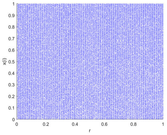
Figure 1.
Distribution diagram of the logistic–tent compound chaotic mapping.
The trajectory distribution plot of the logistic–tent composite chaotic mapping, as shown in Figure 1, reveals that variables x and y in this chaotic mapping can access or gradually approach the entire data range. The trajectory is uniformly distributed across the entire phase plane, indicating the robust chaotic behavior of the logistic–tent composite chaotic mapping across the entire parameter range [38]. In comparison to logistic and tent chaotic mappings, the logistic–tent composite chaotic mapping exhibits more pronounced chaotic characteristics. The combination of the two enhances the complexity and randomness of the chaotic system, contributing to better coverage of the search space.
Utilizing the logistic–tent composite chaotic mapping for population initialization in the SSA effectively combines the randomness and complexity of chaotic systems, contributing to an improved global search capability. This aids in more effectively traversing the solution space and discovering the global optimal solution or better solutions.
2.2.2. Elite Opposition-Based Learning Strategy
The opposition-based learning strategy (OBL) [39] is a novel strategy proposed in the field of computational intelligence. Existing research has shown that, compared to the current solution, there is an approximate 50% likelihood that the inverse solution is in proximity to the global optimum. By employing this strategy, it is possible to effectively enhance the diversity of the population, thereby improving the global search efficiency of the algorithm.
The elite opposition-based learning strategy (EOBL) [40], in comparison to OBL, is more adept at finding global optimal solutions within the current search space. This strategy employs individuals to construct an oppositional population and simultaneously selects from the producer population within the sparrow population, enhancing the quality of the producer population and augmenting population diversity, thus laying the foundation for better global search outcomes.
If is a regular particle with its corresponding self-best value being the elite particle , then the elite oppositional solution can be defined as
where . represents a random number that adheres to a normal distribution. denotes the dynamic boundary of the j-dimensional search space, which can be computed using Equation (11).
Utilizing dynamic boundaries in place of fixed boundaries for the search space allows for the accumulation of search experience, positioning the generated reverse solution within a progressively shrinking search space, thereby expediting the algorithm’s convergence. If the generated oppositional solution lies outside the boundaries, it is reset using a method of random generation. This is illustrated by
2.2.3. Dynamic Self-Adaptive Position Update Strategy
- (1)
- Improved Formula for Producer Position Update
As indicated by Equation (5), during the predation process, the producer updates its position through a step size factor . With the increase in iteration times, the step size factor decreases non-linearly, and the producer gradually establishes an encircling formation in this process. The advantage of this position update method is that it gradually narrows the search scope of the sparrow population, thereby enhancing the algorithm’s local search capability. However, due to the excessive concentration of the population, the algorithm tends to lose its diversity in the later stages of iteration. This insufficient search range makes it prone to fall into local optima, thereby reducing the algorithm’s global search precision. In the position update formula for producers, this paper incorporates the global optimal solution from the preceding generation. Thus, the updated position of the producer is influenced both by the position of the previous generation’s producer and its global optimal solution. Adopting this strategy can effectively reduce the likelihood of the algorithm getting trapped in local optima. Additionally, we incorporate the sine-cosine optimization algorithm (SCA) [41] to modify the producer’s position update formula, introducing a dynamic weight factor that starts with a larger value in the early iterations and adaptively decreases as iterations progress. Implementing this strategy ensures a more effective blend of global exploration and local search, ultimately boosting the algorithm’s rate of convergence.
The formula for the dynamic weight factor and the improved producer’s position update method are presented as
where is a random number within the range of , denotes a random number within the range of , and represents the current global optimal position.
- (2)
- Improved Formula for Scrounger Position Update
When the producer undergoes a certain number of iterations without changes in fitness value, the producer will transform into a producer. In order to avoid the algorithm from being ensnared in local optima, the Lévy flight strategy [42] is introduced into the producer position update formula to enhance the global search capability of the SSA. It is defined as
where and are standard normal distribution random numbers within the range of [0, 1], , and can be solved by
where is the gamma function, which is denoted as .
The improved formula for producer position update is as follows:
where is the current optimal position of the producer.
2.2.4. Optimal Position Perturbation Strategy
In the later iterations of the SSA, the sparrow population progressively approaches optimal individuals, causing a reduction in population diversity and rendering the algorithm susceptible to local optima. To tackle this problem, this study introduces a Cauchy-t perturbation strategy to disturb the top-ranked sparrow individuals. By comparing positions before and after perturbation, superior positions are selected to enter the subsequent iteration, thereby enhancing the algorithm’s capability to break free from local optima.
Inspired by reference [26], the Cauchy-t perturbation operator is constructed, with its expression given by
where is a random number following the standard Cauchy distribution, and stands for a t-distributed random number with its degrees of freedom determined by the maximum number of iterations. The Cauchy distribution operator possesses strong perturbation capabilities, contributing to the enhanced global search performance of the algorithm. The t-distribution exhibits similar characteristics to the Cauchy distribution when its degrees of freedom are low, showcasing robust perturbation capabilities. However, when the degrees of freedom are high, it demonstrates Gaussian distribution characteristics, which can enhance the algorithm’s local search capability.
In Equation (19), the combination of random numbers following the Cauchy distribution and t-distribution is achieved through and , where and are adaptive dynamic parameters varying with the number of iterations. During the initial stages of the algorithm, the higher value of indicates a more significant influence of the Cauchy perturbation, allowing for perturbations of the optimal sparrow position within a larger search range to enhance the algorithm’s global search capability. In the subsequent iterations, the larger value of implies a more pronounced effect of the t-distribution perturbation, facilitating exploration near the optimal sparrow position and enhancing the algorithm’s local exploitation capability, thus enhancing the convergence accuracy of the SSA.
2.2.5. Improved Algorithm Flow
The specific implementation process of the MISSA is as follows:
- Step 1: Initialize parameters. These include population size, maximum number of iterations, proportion of producers, proportion of scouters, warning threshold, and safety threshold.
- Step 2: Initialize the population through the application of logistic–tent chaotic mapping, calculate the fitness value for each sparrow, sort them, and identify the current best and worst fitness values along with their corresponding sparrow positions.
- Step 3: Apply the EOBL strategy proportionate to the number of producers, combined with fitness value sorting, to select top-ranked sparrows as producers and update their positions according to Equations (13) and (14).
- Step 4: The remaining sparrows function as producers and update their positions using Equation (17).
- Step 5: Based on the proportion of scouters, randomly select scouters from the sparrow population and update their positions by using Equation (5).
- Step 6: Compute the fitness value for each sparrow and sort them. When the sparrow individuals gather to a certain extent, apply the Cauchy perturbation strategy to disturb the optimal sparrow position.
- Step 7: Compare the newly perturbed fitness value with the original value and update individual positions accordingly.
- Step 8: Determine whether the maximum iteration count has been reached. If true, end the loop, output, and record the optimal result. If not, proceed to step 3.
- Step 9: Output the global optimal path and its corresponding fitness value.
3. Integration of Enhanced DWA for Dynamic Path Planning
MISSA has optimized and improved upon the issues present in the basic SSA. By specifying the starting point and destination on the grid map, MISSA can produce an optimal global path from the initial point to the endpoint. However, due to the absence of dynamic obstacle information in MISSA, real-time dynamic obstacle avoidance cannot be performed. To address this issue, this paper integrates MISSA with the DWA algorithm. Once MISSA has planned a global path, a local motion strategy for the robot is developed based on global path information and real-time obstacle data, achieving both global path optimization and local dynamic obstacle avoidance for the mobile robot.
3.1. Improvements to the DWA
The DWA involves sampling multiple sets of velocity pairs in the velocity space, simulating the robot’s trajectory under these velocity spaces, and then using an evaluation function to assess the simulated trajectories. The optimal trajectory and corresponding velocity pair are selected from these evaluations to achieve local dynamic path planning [43]. Building upon the robot’s motion model and velocity sampling, this paper enhances the evaluation function of the DWA by incorporating a velocity-adaptive adjustment strategy.
3.1.1. Establishment of Robot Kinematic Model
To perform velocity and motion trajectory simulation in the DWA algorithm, it is essential to establish a kinematic model. The motion model for the robot to perform uniform motion within time is as follows:
The kinematic model of the robot is illustrated in Figure 2.
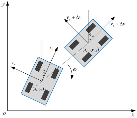
Figure 2.
Robot kinematic model.
3.1.2. Velocity Sampling
After establishing the robot’s kinematic model, its motion trajectory is predicted through velocity sampling. During velocity sampling, multiple sets of sampled velocities are usually obtained to create a dynamic window of velocities. These sampled velocities are evaluated using a cost function to determine the relatively optimal velocities at different moments. Based on this evaluation, the robot’s motion trajectory is projected. Within the velocity space , multiple sets of velocity pairs exist, and due to the robot’s inherent characteristics and environmental constraints, velocities are restricted within a certain range.
- (1)
- Robot’s Maximum and Minimum Velocities:
- (2)
- Robot’s Intrinsic Constraints
Considering the constraints imposed by actual motor torque, the robot is subject to maximum acceleration and deceleration. The velocity constraint formula is provided in Equation (21).
where represents the velocity space achievable by the robot, and are the linear and angular velocities at the current moment, and and denote the maximum acceleration of the robot. and represent the maximum deceleration.
- (3)
- Constraints on Obstacle Safety Distance
To guarantee the robot’s safety throughout its movement, specific constraints are required to maintain a certain distance between the robot and obstacles. In cases where obstacles appear on the predicted trajectory, the robot can reduce its velocity to 0 m/s before encountering the obstacle. The precise constraint formula is provided as Equation (22).
where A represents the closest distance between the simulated trajectory corresponding to velocity space B and obstacles.
3.1.3. Adaptive Velocity Adjustment Strategy
In the DWA, the magnitudes of the robot’s linear and angular velocities are adjusted based on the difference between the optimal trajectory and the robot’s orientation , ensuring relatively stable speed. In environments with denser obstacles, failing to promptly adjust the speed could lead to excessively small turning angles and increase the risk of collision with obstacles. Therefore, in more intricate settings, a lower linear velocity and a higher angular velocity are employed to enable smoother motion, ensuring that the planned path closely aligns with the optimal path, facilitating quicker attainment of the target point, and enhancing algorithm efficiency. Linear-velocity adjustment and angular-velocity adjustment are represented as follows:
where represents the robot’s linear velocity. denotes the robot’s navigable area. corresponds to the robot’s maximum exploration area. signifies the robot’s angular velocity. and are dynamic adjustment parameters.
3.1.4. Optimization of DWA’s Evaluation Function
To tackle the problem of traditional DWA easily getting stuck in local optima, the global path generated by MISSA is introduced to guide the DWA in local dynamic planning. To make the local dynamic path closer to the global path and more efficiently reach the local sub-goal point, a global path deviation cost evaluation function is added to the evaluation function. This evaluation function combines global path information, calculating the distance between the local motion trajectory and the global path, as illustrated in Figure 3. The formula is as follows:
where and are the coordinates of sampling points on the global planning path, and and are the coordinates of sampling points on the local path trajectory. represents the total number of sampling points.
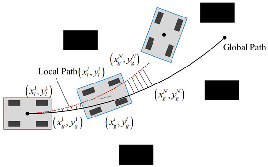
Figure 3.
Schematic diagram of the global path deviation cost evaluation function.
In response to dynamic obstacles, an optimization is applied to the distance evaluation function in the traditional DWA. The distance evaluation function is divided into two components, and , specifically designed to assess the distance between the robot and static obstacles and dynamic obstacles. Different safety distances are established for static and dynamic obstacles.
Consider the coordinates of a static obstacle as , and let represent the minimum distance between the motion trajectory at time and the static obstacle. denotes the radius of the mobile robot’s chassis. For irregularly shaped robots, the maximum chassis radius is taken as , with an additional 0.15 added to ensure a safe distance from static obstacles. The constraint formula is expressed as follows:
Suppose the dynamic obstacle’s coordinates are denoted as , and let represent the minimum distance between the robot’s motion trajectory at time and the dynamic obstacle. represents the robot’s velocity at the time , while stands for the robot’s path of movement within the time interval . Considering the presence of variable acceleration, this path is expanded to 1.15 times its original length to guarantee a safe distance between the robot and the dynamic obstacle. The constraint formula is outlined as follows:
In conclusion, the improved evaluation function for the DWA is
where represents the smoothing coefficient, while , , , , and represent the weighted coefficients of the corresponding functions.
3.2. Fusion Algorithm for Dynamic Path Planning
The optimized MISSA can rapidly acquire global path information, excelling in simple environments with only static obstacles. However, the generated global path lacks smoothness and does not account for newly introduced obstacles, rendering it ineffective against real-time obstacle avoidance in intricate environments. Conversely, the DWA utilizes the robot’s sensing range as a window, continuously refreshing it over time to detect the presence of dynamic obstacles in the robot’s vicinity, thus possessing a degree of dynamic obstacle avoidance capability. However, the DWA lacks global path guidance and is prone to local optima, leading to failure in reaching the target point. To address these issues, this study combines the MISSA and DWA to propose a new approach to mobile robot dynamic path planning, termed MISSA-DWA. The primary procedure of this algorithm is as follows: In the context of a known global map, MISSA conducts global static path planning. Key points are then extracted from the global path generated by MISSA and are used as local sub-target points for the DWA. The DWA is employed for local dynamic path planning in segments, ensuring the robot’s real-time obstacle avoidance. This guarantees that the ultimately generated path is globally optimal and free from collisions. The integrated algorithm effectively leverages the strengths of both methods, reducing the number of path turning points while enhancing path smoothness and safety. The path-planning process of the MISSA-DWA fusion algorithm is depicted in Figure 4.
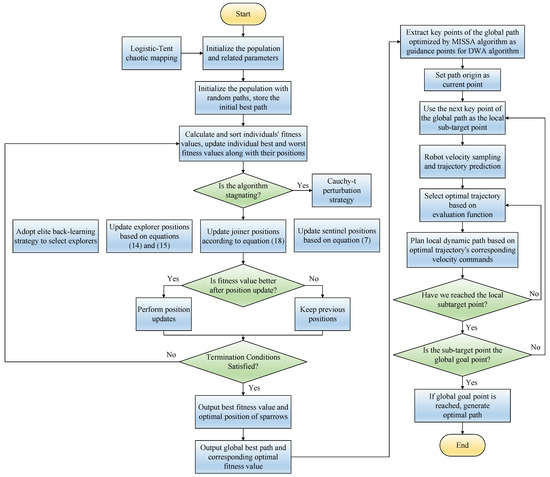
Figure 4.
Path-planning process diagram of the MISSA-DWA fusion algorithm.
4. Simulation and Experimental Results Analysis
4.1. Environment Modeling
Environment modeling is a crucial step in robot path planning. Common methods for environmental modeling include grid-based methods, topological methods, and visibility graph methods [44]. This study adopts a grid-based approach for environmental representation. In the grid map, grid cells are binarized according to Equation (32) to establish the grid map. A value of 0 represents free traversable space, while 1 denotes obstacles. An illustrative grid map example is depicted in Figure 5, where the workspace is divided into white and black grid cells. Here, black grid cells symbolize obstacle regions that are inaccessible to the robot, while white grid cells represent areas traversable by the robot. Therefore, the task of charting paths for mobile robots within complex environments transforms into the objective of determining the most efficient route from the starting point to the destination, utilizing a grid map model under defined constraints [45,46].
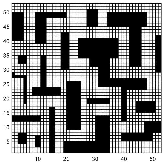
Figure 5.
Grid-based terrain model.
4.2. Simulation Experimental Environment
To guarantee the integrity and comparability of our experimental results, all simulation experiments adhered to uniform configurations. A grid-based approach was employed to construct grid maps for the simulation experiments. The computer processor used was an AMD R7-6800H with a clock frequency of 3.20 GHz, the operating system was Windows 11 (64-bit), and the system had 16 GB of memory. MATLAB R2022b served as the simulation platform.
4.3. Simulation Comparative Experiment of MISSA Global Path Planning
To validate the superior performance of the MISSA, this paper juxtaposes it with the conventional ACO, improved ant colony optimization (IACO), and SSA by performing simulations on two grid maps with distinct complexities. Simulation analysis is conducted on 20 × 20 grid maps of varying complexities. Crucially, to authenticate the algorithm’s efficiency, parameter configurations for both the SSA and the MISSA are kept uniform. Table 1 delineates the parameter specifications for both the sparrow search and ant colony optimization algorithms.

Table 1.
Algorithm parameter settings.
4.3.1. Environment Model 1
In environment model 1, obstacles were sparsely distributed and simulations were executed on a 20 × 20 grid map within MATLAB. Figure 6 visually represents the path-planning outcomes of ACO, IACO, SSA, and MISSA. To minimize the impact of random variables, each algorithm underwent 50 repetitive simulation trials. The comparative performance evaluation of these four algorithms is encapsulated in Table 2.

Figure 6.
The trajectories of four path-planning algorithms within environment model 1: (a) ACO; (b) IACO; (c) SSA; (d) MISSA. The initial point is depicted by a red dot, while the termination point is denoted by a green dot.

Table 2.
Comparison of performance indicators for algorithms (ACO, IACO, SSA, and MISSA) under environment model 1.
Simulation outcomes reveal that all four algorithms are adept at devising collision-free global paths. Analyzing path length, total rotation angle, and runtime from 50 simulation trials, the MISSA emerged superior in path efficiency, charting the shortest path of 27.1290 m. This trims the shortest path lengths determined by the ACO, IACO, and SSA by 3.60%, 2.79%, and 4.28%, respectively. Its average path lengths also undercut theirs by 8.76%, 7.09%, and 15.31%, respectively. In rotation metrics, MISSA exhibited commendable precision. It slashed the minimal total rotation angle relative to paths from ACO, IACO, and SSA by 88.71%, 61.90%, and 77.98%, respectively. Similarly, the average rotation angles were curtailed by 91.68%, 66.99%, and 80.60%. When clocking runtime, MISSA proved to be more time-efficient. Its minimal runtime surpassed ACO, IACO, and SSA by shrinking durations by 21.45%, 88.92%, and 13.54%, respectively. Likewise, average runtimes dwindled by 47.48%, 88.39%, and 41.84% compared to the other algorithms.
4.3.2. Environment Model 2
To bolster the assertion of the enhanced algorithm’s supremacy, more complex obstacles are added to the grid map for simulation experiments. Figure 7 distinctly displays the path optimization outcomes for ACO, IACO, SSA, and MISSA. After conducting 50 iterative experiments, Table 3 provides a comprehensive performance comparison of these four algorithms.

Figure 7.
The trajectories of four path-planning algorithms within environment model 2: (a) ACO; (b) IACO; (c) SSA; (d) MISSA. The initial point is depicted by a red dot, while the termination point is denoted by a green dot.

Table 3.
Comparison of performance indicators for algorithms (ACO, IACO, SSA, and MISSA) under environment model 2.
From the simulation results of the four algorithms, the MISSA’s planned path stands out as the shortest, measuring at 34.3719 m. This is a reduction of 9.24%, 6.15%, and 4.98% compared to the shortest paths from the ACO, IACO, and SSA, respectively. In terms of average path lengths, the MISSA outperforms with a reduction of 19.55%, 9.81%, and 11.92% relative to the aforementioned algorithms. Regarding rotation angles, the MISSA’s minimal total rotation angle is 57.75%, 35.96%, and 20.86% less than the ACO, IACO, and SSA paths, respectively. The average rotation angles also show marked improvement, declining by 77.19%, 69.17%, and 57.79% for the respective algorithms. In runtime efficiency, the MISSA demonstrates significant prowess. Its fastest runtime is shorter by 69.77%, 82.71%, and 20.70% compared to the ACO, IACO, and SSA. The average runtimes also see notable reductions of 71.03%, 86.53%, and 33.23% compared to the trio of algorithms.
From the aforementioned experimental results, it is evident that the MISSA introduced in this study is adept at crafting globally optimal paths across diverse grid map complexities. The generated global path consistently outperforms the other three benchmarked algorithms, excelling in metrics like path length, total rotation angle, and runtime. Beyond its superior path optimization prowess, the MISSA also showcases remarkable stability and the ability to produce smooth paths.
4.4. Analysis of Random Obstacle Avoidance in the Fusion Algorithm
In a grid map of the same environment, four sets of simulation experiments were designed to validate the integrated algorithm. The path planning was conducted using both the MISSA and the combined MISSA-DWA method. The starting and ending grids were marked as “S” and “G”, respectively. Various quantities of random obstacles, represented as blue rectangles, were added to the grid map. The parameters for the DWA are set as follows: the maximum linear velocity is 1 , the maximum linear acceleration is 0.3 , the maximum angular velocity is 30 , the maximum angular acceleration is 50 , the velocity resolution is 0.01 , the angular velocity resolution is 1.0 , the time resolution is 0.1 s, and the prediction period is 3.0 s. The parameters for the evaluation function are set as , , , , and .
Figure 8 displays the simulation outcomes for random obstacle avoidance. The path plotted by the MISSA is illustrated in red, whereas the blue pathway symbolizes the path designed using the MISSA-DWA fusion method. From these simulations, it becomes evident that in the absence of random obstacles, both algorithms can achieve optimal paths. However, when confronted with random obstacles, the MISSA, relying solely on global map data, fails to recognize and subsequently avoid these obstructions. Conversely, the MISSA-DWA approach seamlessly integrates real-time obstacle evasion for sporadic barriers while ensuring path fluidity. As the quantity of random obstacles rises, the designed route consistently demonstrates its efficacy in bypassing impediments and securing a successful arrival at the intended destination. In essence, the introduced hybrid methodology proficiently negotiates random obstacles within grid maps, delivering a streamlined route that closely mirrors the globally optimal trajectory. Pertinent performance metrics for random obstacle sidestepping, utilizing the fusion algorithm, are detailed in Table 4.

Figure 8.
Diagram illustrating the trajectory for random obstacle avoidance in path-planning scenarios: (a) without random obstacles; (b) with one added random obstacle; (c) including two random obstacles; (d) including two random obstacles.

Table 4.
Path-planning performance of the MISSA-DWA fusion algorithm.
4.5. Dynamic Path Planning with the Fusion Algorithm
In an effort to robustly assess the obstacle evasion capabilities of the MISSA-DWA fusion algorithm within dynamic environments, simulations were executed across four types of environmental models on a 50 × 50 grid map. A certain number of dynamic obstacles and random unknown obstacles are introduced into the experimental environment. “S” and “G” identify the starting and ending grid cells, respectively. The green cursor reflects the robot’s directional sensing. Dynamic obstacles are illustrated as pink orbs, with their origins and movement paths depicted by light pink dots and dashed lines. Blue rectangles represent unpredictable obstructions. The trajectory crafted by the MISSA is denoted in red, while the fusion algorithm’s real-time navigation is rendered in blue, emphasizing the fusion algorithm’s agility in swiftly adapting to dynamic changes.
From Figure 9a, it is evident that the robot follows the path prescribed by the MISSA until it encounters the first unknown obstacle. Upon detecting this unknown static obstacle and assessing the robot’s relative position and motion status in relation to it, there is a foreseen risk of a collision along the original trajectory. Consequently, the fusion algorithm is activated to engage in local obstacle avoidance, effectively circumventing the unknown obstacle. Subsequently, the robot recalibrates its route to converge with the optimal path generated by the MISSA. As illustrated in Figure 9b, the robot detects a dynamic obstacle at that location and, foreseeing a potential side collision, employs a local obstacle avoidance strategy after determining the dynamic obstacle’s movement direction. Through four instances of real-time obstacle avoidance scenarios involving both unknown static and dynamic obstacles, the robot successfully reaches the target point, as evidenced in Figure 9c.
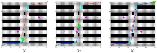
Figure 9.
Dynamic obstacle avoidance effect of the MISSA-DWA fusion algorithm in environment 1: (a) avoiding the random obstacle; (b) avoiding the dynamic obstacle; (c) completed dynamic path planning to reach the target point.
In Figure 9, it is evident that the robot, commencing its journey from the initial point, consistently demonstrates the ability to promptly and accurately employ appropriate obstacle avoidance strategies when confronted with lateral and frontal collisions involving random unknown obstacles and dynamic obstacles along the global path. This capability enables the robot to discern a smooth and secure path, ultimately achieving the anticipated outcome of algorithm fusion.
To further substantiate the efficacy of the proposed fusion algorithm, a series of dynamic path-planning simulations were executed under diverse scenarios. The paths generated by the fusion algorithm were juxtaposed with the globally planned paths determined by the MISSA to ascertain the dynamic obstacle avoidance performance outlined in this paper. The simulation results encompassing three distinct complexity levels of environments are illustrated in Figure 10.

Figure 10.
MISSA-DWA fusion algorithm’s dynamic obstacle avoidance effect. (a) Simulation diagram 1 in environment 2; (b) simulation diagram 2 in environment 3; (c) simulation diagram 3 in environment 4; (d) simulation diagram 4 in environment 4.
Summarizing the simulation results across the four environments, it can be inferred that in environments containing both unknown static and dynamic obstacles, the enhanced MISSA’s planning process, which does not rely on dynamic grid information, generates paths consistent with those in static environments. As a consequence, it lacks real-time dynamic obstacle avoidance capabilities, rendering it incapable of maneuvering around dynamic obstacles. In contrast, the proposed MISSA-DWA algorithm, coupled with the improved DWA algorithm, demonstrates the ability to perform real-time local dynamic path planning based on the global path. It successfully navigates around newly introduced unknown static and dynamic obstacles, crafting smooth paths that strike a balance between global optimality and effective obstacle avoidance. The algorithm adapts seamlessly to complex dynamic obstacle environments, thereby enhancing the operational efficiency of the robot.
4.6. Experimental Validation
To further assess the effectiveness of the algorithm in real-world applications, practical robot path-planning experiments were conducted in an actual environment. The current study utilized the Songling Robot SCOUT2.0 robot chassis, equipped with a Velodyne 16-line LiDAR sensor and integrated with the ROS system on the host computer. The host computer facilitated control over the robot and its sensors, enabling the collection of environmental data. The Gmapping-SLAM algorithm was employed to generate a two-dimensional grid map of the experimental surroundings. The resulting grid map was saved in image format, with white areas denoting explored and unoccupied regions, black areas indicating detected obstacles, and gray areas representing inflated obstacle boundaries. Subsequently, the MISSA and MISSA-DWA fusion algorithms were validated within the constructed grid map.
The experiments in a real-world environment are divided into static and dynamic components. In the static path-planning experiment, the first step involves constructing the environmental map and launching the Rviz platform. Subsequently, the robot’s initial and destination points are specified, and the MISSA-DWA fusion algorithm is invoked to facilitate global path planning for the robot, guiding it from the starting point to the target point within a static environment. The robot adheres to the planned path as it progresses toward the destination. The experimental procedure, as depicted in Figure 11 and Figure 12, illustrates that the mobile robot departs from its initial position and adeptly navigates around all static obstacles throughout the entire movement process. Eventually, the robot safely arrives at the target point by following the globally optimal path. The feedback of robot control parameters during the experiment is shown in Figure 13.
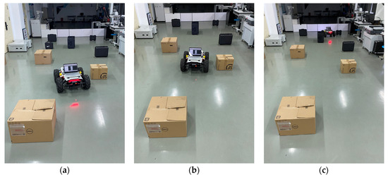
Figure 11.
Obstacle avoidance process in a static environment.(a) obstacle avoidance process 1; (b) obstacle avoidance process 2; (c) reaching the target point.
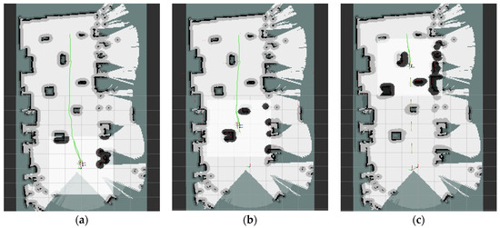
Figure 12.
Path planning in a static environment. (a) the mobile robot starts to move (b) obstacle avoidance process 1. (c) obstacle avoidance process 2.
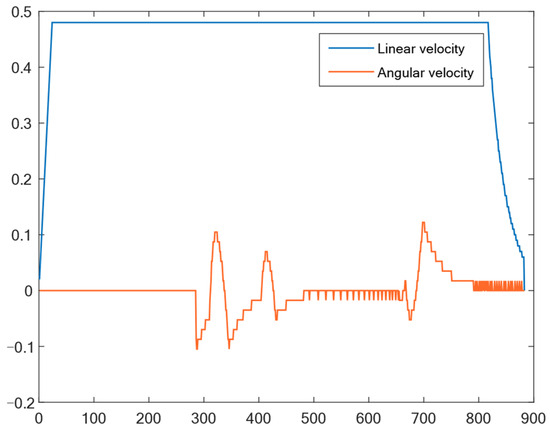
Figure 13.
Output results of linear velocity and angular velocity in a static environment.
To assess the robot’s capability to avoid dynamic obstacles during its movement, a small mobile robot was introduced as a dynamic obstacle in the experimental environment, as depicted in Figure 14. The experimental procedure, as illustrated in Figure 14 and Figure 15, demonstrates that after the robot plans its global path and embarks on its journey, the dynamic obstacle robot is activated and positioned onto the pre-planned global path. As the dynamic obstacle enters the detection range of the local path-planning algorithm, the robot promptly identifies and responds, utilizing the fusion algorithm for local dynamic obstacle avoidance. This enables successful avoidance of the dynamic obstacle, as depicted in Figure 15a,c. Subsequently, the robot continues its movement toward the planned global optimal path and ultimately reaches the target point. The experimental results in Figure 14 and Figure 15 illustrate that the proposed fusion algorithm ensures smooth motion paths while effectively evading dynamic obstacles in the environment, thereby validating the algorithm’s effectiveness. The feedback of robot control parameters during the experiment is shown in Figure 16.
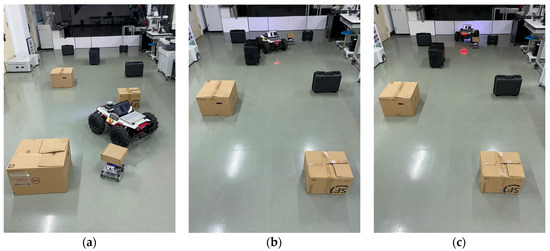
Figure 14.
Obstacle avoidance process in a dynamic environment 1. (a) obstacle avoidance process 1. (b) obstacle avoidance process 2. (c) reaching the target point.
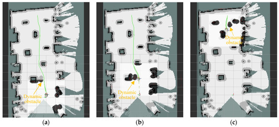
Figure 15.
Path planning in dynamic environment 1. (a) the mobile robot starts to move (b) obstacle avoidance process 1. (c) obstacle avoidance process 2.
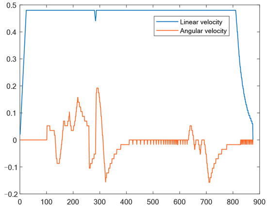
Figure 16.
Output results of linear-velocity and angular-velocity dynamic environment 1.
To further validate the proposed algorithm and its effectiveness, experiments were conducted in a more complex map environment. Additional randomly shaped static obstacles and dynamic obstacles were introduced into the experimental environment. In the more complex conditions, as shown in Figure 17 and Figure 18, two blue benches and a barrel were added as new random static obstacles, and a small mobile robot served as a dynamic obstacle. The experimental results demonstrate that the mobile robot can still plan its path reasonably based on the algorithm and navigate around static and dynamic obstacles effectively, ensuring the robot reaches the target point safely. This further validates the effectiveness of the algorithm. The feedback of robot control parameters during the experiment is shown in Figure 19.
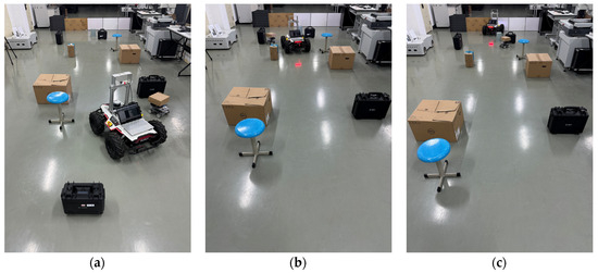
Figure 17.
Obstacle avoidance process in dynamic environment 2. (a) obstacle avoidance process 1. (b) obstacle avoidance process 2. (c) reaching the target point.
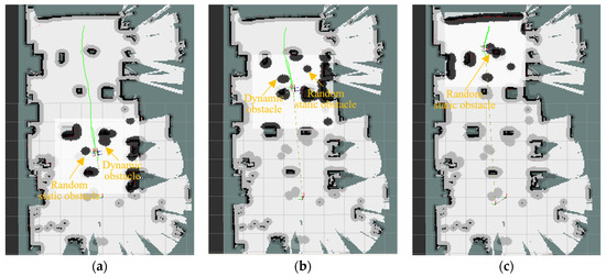
Figure 18.
Path planning in a dynamic environment 2. (a) obstacle avoidance process 1. (b) obstacle avoidance process 2. (c) obstacle avoidance process 3.
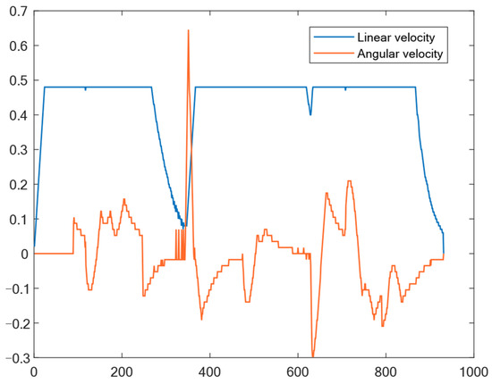
Figure 19.
Output results of linear-velocity and angular-velocity dynamic environment 2.
5. Conclusions
In response to the shortcomings and limitations of the basic SSA in path planning, as well as the challenges posed by dynamic path planning for mobile robots, this study introduces a novel approach that combines the enhanced SSA with the DWA. Through a comparative analysis of path length, total rotation angle, and algorithm execution time for static path planning, along with the execution of obstacle avoidance experiments in dynamic path planning under various scenarios, the following conclusions can be drawn:
- Initially, logistic–tent chaotic mapping is utilized to initialize the sparrow population, generating a relatively evenly distributed and stable initial population. Subsequently, an elite reverse learning strategy is employed to select producers, which forms the foundation for algorithm stability. Following this, a dynamic self-adaptive position update strategy is integrated to enhance the optimization capability of the algorithm. This improvement involves refining the position update formulas for both producers and scroungers. Additionally, the Lévy flight strategy is applied to update the positions of scroungers, accompanied by the incorporation of a best position perturbation strategy to further enhance the algorithm’s ability to escape local optima. Through comparative experiments in static environments and obstacle avoidance experiments in various dynamic environment scenarios, the results demonstrate that the global paths planned by MISSA outperform those generated by the other three comparative algorithms in terms of path length, total rotation angle, and algorithm runtime. These findings underscore MISSA’s robust path optimization capability and stability.
- The evaluation function of the DWA is refined, and an adaptive velocity adjustment strategy is introduced. Subsequently, MISSA is integrated with the optimized DWA, utilizing the key points of the global path generated by MISSA as local sub-goals for the DWA. This integration results in the development of MISSA-DWA. Through path-planning experiments conducted in diverse dynamic environments and scenarios, it is concluded that the integrated MISSA-DWA algorithm not only devises globally optimal paths but also excels in generating smooth paths while dynamically navigating around obstacles. It effectively avoids unidentified obstructions, ensuring the secure arrival of the robot at the target destination. This enhancement significantly improves the efficiency and safety of the robot’s movement.
Moreover, the research in this paper still has certain limitations. The main directions for future research plans are twofold. In terms of algorithms, researchers should consider trying other strategies to further optimize the algorithm’s performance. Simultaneously, researchers should comprehensively consider factors such as the traversal cost of different areas, changes in terrain height, and the different costs of uphill and downhill traversal in the environmental map to enhance the practicality of the algorithm. On the application front, there is a contemplation of applying the algorithm to multi-objective planning and multi-robot planning issues.
Author Contributions
Conceptualization, J.H., W.J. and L.Y.; methodology, J.H., W.J., Z.L. and L.Y.; software, J.H.; validation, J.H. and W.J.; investigation, J.H.; resources, Z.L.; data curation, J.H., W.J. and L.Y.; writing—original draft preparation, J.H. and W.J.; writing—review and editing, J.H. and W.J.; project administration, W.J., Z.L., X.H. and B.G.; supervision and funding acquisition, Z.L., X.H. and B.G. All authors have read and agreed to the published version of the manuscript.
Funding
This research was funded by the National Natural Science Foundation of China (Grant No. 52005471 and 52075511) and the National Key Research and Development Program of China (Grant No. 2022YFF0705704).
Data Availability Statement
The data used to support the findings of this study are available from the first author upon request.
Conflicts of Interest
The authors declare that they have no known competing financial interests or personal relationships that could have appeared to influence the work reported in this paper.
References
- Duan, L.-M. Path Planning for Batch Picking of Warehousing and Logistics Robots Based on Modified A* Algorithm. Int. J. Onl. Eng. 2018, 14, 176. [Google Scholar] [CrossRef]
- Tong, X.; Yu, S.; Liu, G.; Niu, X.; Xia, C.; Chen, J.; Yang, Z.; Sun, Y. A Hybrid Formation Path Planning Based on A* and Multi-Target Improved Artificial Potential Field Algorithm in the 2D Random Environments. Adv. Eng. Inform. 2022, 54, 101755. [Google Scholar] [CrossRef]
- Zhang, Z.; Chen, J.; Guo, Q. Application of Automated Guided Vehicles in Smart Automated Warehouse Systems: A Survey. Comput. Model. Eng. Sci. 2022, 134, 1529–1563. [Google Scholar] [CrossRef]
- Suresh, K.S.; Venkatesan, R.; Venugopal, S. Mobile Robot Path Planning Using Multi-Objective Genetic Algorithm in Industrial Automation. Soft Comput. 2022, 26, 7387–7400. [Google Scholar] [CrossRef]
- Bai, X.; Jiang, H.; Cui, J.; Lu, K.; Chen, P.; Zhang, M. UAV Path Planning Based on Improved A∗ and DWA Algorithms. Int. J. Aerosp. Eng. 2021, 2021, 4511252. [Google Scholar] [CrossRef]
- Hu, X.; Luo, Z.; Jiang, W. AGV Localization System Based on Ultra-Wideband and Vision Guidance. Electronics 2020, 9, 448. [Google Scholar] [CrossRef]
- Zhong, X.; Tian, J.; Hu, H.; Peng, X. Hybrid Path Planning Based on Safe A* Algorithm and Adaptive Window Approach for Mobile Robot in Large-Scale Dynamic Environment. J. Intell. Robot. Syst. 2020, 99, 65–77. [Google Scholar] [CrossRef]
- Soltani, A.R.; Tawfik, H.; Goulermas, J.Y.; Fernando, T. Path Planning in Construction Sites: Performance Evaluation of the Dijkstra, A∗, and GA Search Algorithms. Adv. Eng. Inform. 2002, 16, 291–303. [Google Scholar] [CrossRef]
- Han, X.; Zhang, X.; Zhang, H. Trajectory Planning of USV: On-Line Computation of the Double S Trajectory Based on Multi-Scale A* Algorithm with Reeds–Shepp Curves. J. Mar. Sci. Eng. 2023, 11, 153. [Google Scholar] [CrossRef]
- Jhong, B.-G.; Chen, M.-Y. An Enhanced Navigation Algorithm with an Adaptive Controller for Wheeled Mobile Robot Based on Bidirectional RRT. Actuators 2022, 11, 303. [Google Scholar] [CrossRef]
- Wang, Q.; Li, J.; Yang, L.; Yang, Z.; Li, P.; Xia, G. Distributed Multi-Mobile Robot Path Planning and Obstacle Avoidance Based on ACO–DWA in Unknown Complex Terrain. Electronics 2022, 11, 2144. [Google Scholar] [CrossRef]
- Chen, T.J.; Sun, Y.; Dai, W.; Tao, W.; Liu, S. On the Shortest and Conflict-Free Path Planning of Multi-AGV System Based on Dijkstra Algorithm and the Dynamic Time-Window Method. Adv. Mater. Res. 2013, 645, 267–271. [Google Scholar] [CrossRef]
- Li, X.; Jiao, T.; Ma, J.; Duan, D.; Liang, S. LSDA-APF: A Local Obstacle Avoidance Algorithm for Unmanned Surface Vehicles Based on 5G Communication Environment. Comput. Model. Eng. Sci. 2023, 138, 595–617. [Google Scholar] [CrossRef]
- Wang, J.; Luo, Y.; Tan, X. Path Planning for Automatic Guided Vehicles (AGVs) Fusing MH-RRT with Improved TEB. Actuators 2021, 10, 314. [Google Scholar] [CrossRef]
- Miao, C.; Chen, G.; Yan, C.; Wu, Y. Path Planning Optimization of Indoor Mobile Robot Based on Adaptive Ant Colony Algorithm. Comput. Ind. Eng. 2021, 156, 107230. [Google Scholar] [CrossRef]
- Sui, F.; Tang, X.; Dong, Z.; Gan, X.; Luo, P.; Sun, J. ACO+PSO+A*: A Bi-Layer Hybrid Algorithm for Multi-Task Path Planning of an AUV. Comput. Ind. Eng. 2023, 175, 108905. [Google Scholar] [CrossRef]
- Gul, F.; Rahiman, W.; Alhady, S.S.N.; Ali, A.; Mir, I.; Jalil, A. Meta-Heuristic Approach for Solving Multi-Objective Path Planning for Autonomous Guided Robot Using PSO–GWO Optimization Algorithm with Evolutionary Programming. J. Ambient. Intell. Hum. Comput. 2021, 12, 7873–7890. [Google Scholar] [CrossRef]
- Liang, J.-H.; Lee, C.-H. Efficient Collision-Free Path-Planning of Multiple Mobile Robots System Using Efficient Artificial Bee Colony Algorithm. Adv. Eng. Softw. 2015, 79, 47–56. [Google Scholar] [CrossRef]
- Zheng, Y.; Luo, Q.; Wang, H.; Wang, C.; Chen, X. Path Planning of Mobile Robot Based on Adaptive Ant Colony Algorithm. J. Intell. Fuzzy Syst. 2020, 39, 5329–5338. [Google Scholar] [CrossRef]
- Raj, R.; Kos, A. An Optimized Energy and Time Constraints-Based Path Planning for the Navigation of Mobile Robots Using an Intelligent Particle Swarm Optimization Technique. Appl. Sci. 2023, 13, 9667. [Google Scholar] [CrossRef]
- Dong, L.; Yuan, X.; Yan, B.; Song, Y.; Xu, Q.; Yang, X. An Improved Grey Wolf Optimization with Multi-Strategy Ensemble for Robot Path Planning. Sensors 2022, 22, 6843. [Google Scholar] [CrossRef]
- Eshtehardian, S.A.; Khodaygan, S. A Continuous RRT*-Based Path Planning Method for Non-Holonomic Mobile Robots Using B-Spline Curves. J. Ambient. Intell. Hum. Comput. 2023, 14, 8693–8702. [Google Scholar] [CrossRef]
- Zhang, Y.; Wen, Y.; Tu, H. A Method for Ship Route Planning Fusing the Ant Colony Algorithm and the A* Search Algorithm. IEEE Access 2023, 11, 15109–15118. [Google Scholar] [CrossRef]
- Xue, J.; Shen, B. A Novel Swarm Intelligence Optimization Approach: Sparrow Search Algorithm. Syst. Sci. Control Eng. 2020, 8, 22–34. [Google Scholar] [CrossRef]
- Zhang, X.; Xiao, F.; Tong, X.; Yun, J.; Liu, Y.; Sun, Y.; Tao, B.; Kong, J.; Xu, M.; Chen, B. Time Optimal Trajectory Planing Based on Improved Sparrow Search Algorithm. Front. Bioeng. Biotechnol. 2022, 10, 852408. [Google Scholar] [CrossRef]
- Liu, G.; Shu, C.; Liang, Z.; Peng, B.; Cheng, L. A Modified Sparrow Search Algorithm with Application in 3d Route Planning for UAV. Sensors 2021, 21, 1224. [Google Scholar] [CrossRef]
- Zhou, S.; Xie, H.; Zhang, C.; Hua, Y.; Sui, X. Wavefront-Shaping Focusing Based on a Modified Sparrow Search Algorithm. Optik-Int. J. Light. Electron. Opt. 2021, 244, 167516. [Google Scholar] [CrossRef]
- Khedr, A.M.; Vijayan, D.; Salim, A.; Elsway, A.A.; Osamy, W. ESSAIoV: Enhanced Sparrow Search Algorithm-Based Clustering for Internet of Vehicles. Arab. J. Sci. Eng. 2023, 1–27. [Google Scholar] [CrossRef]
- Zhang, Z.; He, R.; Yang, K. A Bioinspired Path Planning Approach for Mobile Robots Based on Improved Sparrow Search Algorithm. Adv. Manuf. 2022, 10, 114–130. [Google Scholar] [CrossRef]
- Geng, J.; Sun, X.; Wang, H.; Bu, X.; Liu, D.; Li, F.; Zhao, Z. A Modified Adaptive Sparrow Search Algorithm Based on Chaotic Reverse Learning and Spiral Search for Global Optimization. Neural Comput. Appl. 2023. [Google Scholar] [CrossRef]
- Khaleel, M.I. Efficient Job Scheduling Paradigm Based on Hybrid Sparrow Search Algorithm and Differential Evolution Optimization for Heterogeneous Cloud Computing Platforms. Internet Things 2023, 22, 100697. [Google Scholar] [CrossRef]
- Lai, X.; Wu, D.; Wu, D.; Li, J.H.; Yu, H. Enhanced DWA Algorithm for Local Path Planning of Mobile Robot. Ind. Robot. Int. J. Robot. Res. Appl. 2023, 50, 186–194. [Google Scholar] [CrossRef]
- Han, S.; Wang, L.; Wang, Y.; He, H. A Dynamically Hybrid Path Planning for Unmanned Surface Vehicles Based on Non-Uniform Theta* and Improved Dynamic Windows Approach. Ocean Eng. 2022, 257, 111655. [Google Scholar] [CrossRef]
- Liu, Q.; Zhang, Y.; Li, M.; Zhang, Z.; Cao, N.; Shang, J. Multi-UAV Path Planning Based on Fusion of Sparrow Search Algorithm and Improved Bioinspired Neural Network. IEEE Access 2021, 9, 124670–124681. [Google Scholar] [CrossRef]
- Khedr, A.M.; Al Aghbari, Z.; Raj, P.P.V. MSSPP: Modified Sparrow Search Algorithm Based Mobile Sink Path Planning for WSNs. Neural Comput. Appl. 2023, 35, 1363–1378. [Google Scholar] [CrossRef]
- Moysis, L.; Petavratzis, E.; Volos, C.; Nistazakis, H.; Stouboulos, I. A Chaotic Path Planning Generator Based on Logistic Map and modulo Tactics. Robot. Auton. Syst. 2020, 124, 103377. [Google Scholar] [CrossRef]
- Li, Y.; Han, M.; Guo, Q. Modified Whale Optimization Algorithm Based on Tent Chaotic Mapping and Its Application in Structural Optimization. KSCE J. Civ. Eng. 2020, 24, 3703–3713. [Google Scholar] [CrossRef]
- Gupta, M.; Gupta, K.K.; Khosravi, M.R.; Shukla, P.K.; Kautish, S.; Shankar, A. An Intelligent Session Key-Based Hybrid Lightweight Image Encryption Algorithm Using Logistic-Tent Map and Crossover Operator for Internet of Multimedia Things. Wirel. Pers. Commun. 2021, 121, 1857–1878. [Google Scholar] [CrossRef]
- Ewees, A.A.; Abd Elaziz, M.; Houssein, E.H. Improved Grasshopper Optimization Algorithm Using Opposition-Based Learning. Expert Syst. Appl. 2018, 112, 156–172. [Google Scholar] [CrossRef]
- Zhang, S.; Luo, Q.; Zhou, Y. Hybrid Grey Wolf Optimizer Using Elite Opposition-Based Learning Strategy and Simplex Method. Int. J. Comput. Intel. Appl. 2017, 16, 1750012. [Google Scholar] [CrossRef]
- Mirjalili, S. SCA: A Sine Cosine Algorithm for Solving Optimization Problems. Knowl.-Based Syst. 2016, 96, 120–133. [Google Scholar] [CrossRef]
- Liu, M.; Yao, X.; Li, Y. Hybrid Whale Optimization Algorithm Enhanced with Lévy Flight and Differential Evolution for Job Shop Scheduling Problems. Appl. Soft Comput. 2020, 87, 105954. [Google Scholar] [CrossRef]
- Chang, L.; Shan, L.; Jiang, C.; Dai, Y. Reinforcement Based Mobile Robot Path Planning with Improved Dynamic Window Approach in Unknown Environment. Auton. Robot. 2021, 45, 51–76. [Google Scholar] [CrossRef]
- Li, C.; Huang, X.; Ding, J.; Song, K.; Lu, S. Global Path Planning Based on a Bidirectional Alternating Search A* Algorithm for Mobile Robots. Comput. Ind. Eng. 2022, 168, 108123. [Google Scholar] [CrossRef]
- Hou, W.; Xiong, Z.; Wang, C.; Chen, H. Enhanced Ant Colony Algorithm with Communication Mechanism for Mobile Robot Path Planning. Robot. Auton. Syst. 2022, 148, 103949. [Google Scholar] [CrossRef]
- Xu, C.; Zhu, H.; Zhu, H.; Wang, J.; Zhao, Q. Improved RRT∗ Algorithm for Automatic Charging Robot Obstacle Avoidance Path Planning in Complex Environments. Comput. Model. Eng. Sci. 2023, 137, 2567–2591. [Google Scholar] [CrossRef]
Disclaimer/Publisher’s Note: The statements, opinions and data contained in all publications are solely those of the individual author(s) and contributor(s) and not of MDPI and/or the editor(s). MDPI and/or the editor(s) disclaim responsibility for any injury to people or property resulting from any ideas, methods, instructions or products referred to in the content. |
© 2024 by the authors. Licensee MDPI, Basel, Switzerland. This article is an open access article distributed under the terms and conditions of the Creative Commons Attribution (CC BY) license (https://creativecommons.org/licenses/by/4.0/).