Abstract
This paper proposes a kinesthetic–tactile fusion feedback system based on virtual interaction. Combining the results of human fingertip deformation characteristics analysis and an upper limb motion mechanism, a fingertip tactile feedback device and an arm kinesthetic feedback device are designed and analyzed for blind instructors. In order to verify the effectiveness of the method, virtual touch experiments are established through the mapping relationship between the master–slave and virtual end. The results showed that the average recognition rate of virtual objects is 79.58%, and the recognition speed is improved by 41.9% compared with the one without force feedback, indicating that the kinesthetic–tactile feedback device can provide more haptic perception information in virtual feedback and improve the recognition rate of haptic perception.
1. Introduction
Advances in human–computer interaction technology [1] have paved the way for the development of haptic feedback devices to enable somatosensory haptics to bring a fuller sense of immersion in a metaverse-based virtual society [2]. Haptic feedback is transmitted to the user through kinesthetic stimulation and skin stimulation, and current haptic feedback devices mainly include kinesthetic feedback devices and skin stimulation feedback devices [3]. In recent years, a variety of haptic feedback devices have been proposed, mainly for medical [4,5], educational [6,7], and other fields [8].
Most existing skin stimulation feedback devices deliver tactile sensation mainly through pressure, vibration, skin stretching, friction, etc. Oliver Ozioko et al. [9] presented a novel tactile sensing device (SensAct) that seamlessly integrated soft touch/pressure sensors on a flexible actuator, embedding the soft sensors in the 3D-printed fingertips of a robotic hand to demonstrate its use of the SensAct device for remote vibrotactile stimulation. Chen Si et al. [10] presented stretchable soft actuators for tactile feedback by matching the skin’s perceptual range, spatial resolution, and stretchability. Francesco Chinello et al. [11] presented a novel wearable fingertip device that moved toward the user’s fingertip via an end-effector, rotating it to simulate contact with an arbitrarily oriented surface while transmitting vibrations to the fingertip via a motor to achieve haptic sensation. Tang Yushan et al. [12] achieved haptic reproduction and visual feedback of a soft tissue model of hand touch by constructing an online system of force and haptics. Yan Yuchao et al. [13] designed a novel arm haptic feedback device that provided vibrotactile feedback through a vibrator attached to the surface of an airbag. Mo Yiting et al. [14] designed a fingertip haptic interaction device with a five-link that was capable of generating 3-DoF force feedback at the fingertip with the fingertip portion of the device weighing only 30 g. However, most existing skin tactile feedback devices provide feedback in the form of vibration or skin deformation, and they are usually worn on or near the user’s fingertips [15]. Skin tactile feedback can provide information to enable the operator to perform a variety of tasks, but it is still lacking in operations, such as suturing and knotting in robot-assisted surgery [16,17] and manipulating objects in virtual reality [18].
Compared to tactile feedback devices, current kinesthetic feedback devices provide feedback through position, velocity, and torque information from the body’s neighboring parts and have the advantages of multiple degrees of freedom (DoF) and a wide dynamic range. Fu Yongqing et al. [19] presented a new method to implement augmented reality (AR) and kinesthetic feedback for remote operation of ultrasound systems to achieve real-time feedback. Giuk Lee et al. [20] designed a column-type force-feedback device in which the entire device was mounted on a column that can move up and down, capable of providing a larger interaction space. Taha Moriyama et al. [21] designed a wearable kinesthetic device that used a five-rod linkage mechanism to present the magnitude and direction of the force applied to the index finger. Ryohei Michikawa et al. [22] designed an exoskeletal haptic glove that fixed the movement of the finger to provide braking force and different types of grip sensations. Most existing devices that provide kinesthetic feedback are grounded and exoskeletal, which leads to the fact that these kinesthetic feedback devices usually have a large footprint and limited portability and wear resistance, which limits their application and effectiveness in many virtual and realistic scenarios. Moreover, grounded kinesthetic feedback devices also limit the range of motion of the operator, as the scaling and friction of the device weight increases with size [23].
Multimodal systems based on tactile and kinesthetic fusion feedback have emerged to display more realistic haptic feedback for operators in virtual environments [24]. Multimodal fusion technology refers to the integration and fusion of information from different sensors and modalities to improve the performance and effectiveness of the system, including sensor fusion, data fusion, and information fusion [25,26,27]. Luo Shan et al. [28] presented a method called Iterative Closest Labeled Point (iCLAP) to link kinesthetic and tactile modalities to achieve integrated perception of the touched object. Fan Liqiang et al. [29] presented a multimodal haptic fusion method of cable-drive and ultrasonic haptics that can generate multimodal haptic stimuli. Hanna Kossowsky et al. [30] designed haptic feedback consisting of force feedback and artificial skin stretching for robot-assisted minimally invasive surgery (RAMIS). In order to achieve accurate haptic control for robotic surgical tasks, Zhu Xinhe et al. [31,32,33] established a force control method based on the Hunt–Crossley model, proposed a nonlinear method for on-line soft tissue characterization, and, based on this, investigated a combination of the Hunt–Crossley contact model with an iterative Kalman filter for a dynamic soft tissue identification method to improve the accuracy of haptic feedback. Francesco Chinello et al. [34] presented a novel modular wearable interface for haptic interaction and robotic teleoperation, consisting of a 3-degrees-of-freedom (3-DoF) fingertip skin device and a 1-DoF finger kinesthetic exoskeleton, with the entire device weighing only 43 g. Kinesthetic fusion is still in its infancy, and existing kinesthetic feedback devices rely mainly on the finger bone part to deliver kinesthetic information, which is not complete compared to the kinesthetic information delivered by the arm. The multimodal fusion in this paper is the fusion of kinesthetic and tactile information, where the kinesthetic information features are obtained by collecting data such as the acceleration and velocity of the arm, the tactile features are reproduced by collecting data such as deformation of the object in the virtual space and the contact force, and the features extracted from both types of modal information are fused to obtain a more accurate and reliable haptic feedback.
Because blind people cannot directly judge whether the objects they touch are dangerous through vision in the process of learning and cognition, there are few similar products for the blind on the market at present. According to the problems and limitations of the current kinesthetic feedback devices and tactile feedback devices in the blind demonstration and teaching, this paper proposes a kinesthetic–tactile fusion feedback system based on the mapping relationship between the master–slave and the virtual end, where the synchronized control of the arms achieves kinesthetic feedback and the tactile transfer of the fingertips achieves tactile feedback.
2. Design and Analysis of Tactile Feedback Device
The purpose of various haptic feedback devices is to be able to deliver controlled and effective stimuli during a human–computer interaction, and the prerequisite for the formation of effective stimuli is a clear understanding of the mechanical properties of the human tactile soft tissue.
2.1. Fingertip Deformation Characteristics Analysis
The distal phalanx is a complex structure consisting mainly of the phalanges, the epidermal layer, and the subcutaneous tissue, as shown in Figure 1. There are some differences in the structural properties of the tissues of each part, with the harder phalanges and nails mainly serving to protect and support the soft tissues of the fingertip. The softer epidermal layer encases the subcutaneous tissue, which contains a large number of nerve endings.
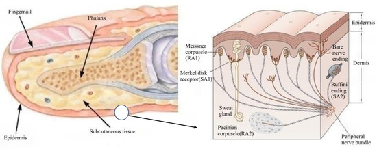
Figure 1.
Organizational chart of the distal phalange.
The subcutaneous tissue is a complex system in which different tactile receptors are distributed. Four types of receptors are important for tactile perception of the fingertip: Meissner vesicles, which perceive edges; Merkel vesicles, which perceive mechanical pressure and low-frequency vibrations caused by shape and texture; Pacinian vesicles, which perceive high-frequency vibratory stimuli; and Ruffini vesicles, which perceive elasticity, are distributed in the finger in the subcutaneous soft tissue.
2.2. Establishment of a Biomimetic Finger
2.2.1. Geometry and Materials
The fingertip geometry is determined by the physical shape of the fingertip of the subject’s index finger. To simulate the shape and structure of the distal phalanx of the human index finger, the established 3D model is imported into Hypermesh for meshing, and the fingertip finite element model has 61,906 segmentation cells, mainly consisting of the finger bone, soft tissue (cuticle, epidermis, dermis, and subcutaneous tissue), and nail, as shown in Figure 2. Fixed constraints are placed on the end faces and nails of the distal fingertip model. The squeeze displacements are 4mm for all different point arrays. The external shape of the fingertip is approximately axisymmetric and the finger belly is approximately elliptical. The fingertip materials [35] used in the model’s are shown in Table 1.
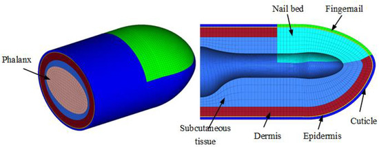
Figure 2.
Fingertip finite element model.

Table 1.
Material constants of the index fingertip.
2.2.2. Simulation of Fingertip Deformation
The finite element model with the mesh divided in Hypermesh is imported into Abaqus 2016 software to establish the numerical simulation. In the simulation, the end of the phalanges and the nail are created with constraints in the same coordinate system to link the soft tissue and the phalanges to ensure the continuity of the mesh.
The fingertip forms an inclination angle of 20° with the horizontal plane, and the displacement of the rigid indenter is perpendicular to its axis. The end face of the distal finger end model is fixedly constrained to simulate the process of compression of the finger belly, and the squeezing pressure, pressure distribution of contact, stress and strain within the soft tissue, and squeezing deformation are set as the output quantities of the simulation. The numerical simulations are carried out for four dot arrays, respectively, as shown in Figure 3. That is, a 2 × 2 dot matrix, 3 × 3 dot matrix, 4 × 4 dot matrix, and flat plate with a single cylinder of 2 mm diameter.
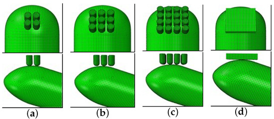
Figure 3.
Analysis of fingertip deformation for different dot patterns: (a) 2 × 2 dot matrix; (b) 3 × 3 dot matrix; (c) 4 × 4 dot matrix; (d) flat plate.
2.2.3. Simulation Results of Fingertip Deformation
The displacement clouds obtained from the numerical simulations for different dot matrix and flat plate extrusion finger bellies are shown in Figure 4. The dot matrix, dot matrix, dot matrix, and flat plate extrusion displacements are all 4 mm.
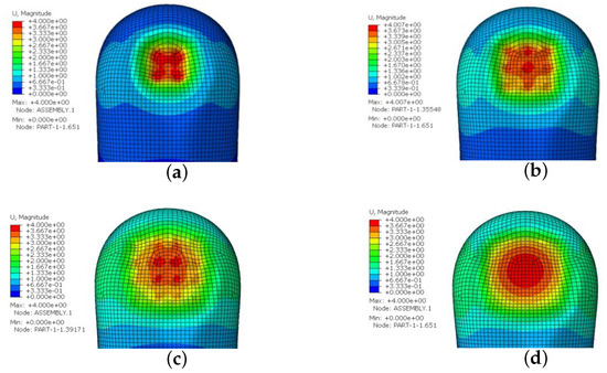
Figure 4.
The displacement cloud of each indenter squeezing finger belly: (a) dot matrix; (b) dot matrix; (c) dot matrix; (d) flat plate.
It can be seen from the figure that the displacement deformation of the skin of the finger belly spreads outward from the contact center of the contact dots and the plate, and the displacement deformation of the contact surface of each dot matrix and the plate is the largest. As the number of dots increases and the material properties of the subcutaneous tissue change, most of the skin on the fingertips becomes deformed. The contact force cloud diagram of different dot matrices and the flat plate extrusion of the finger belly is shown in Figure 4. As the number of dot arrays increases, the maximum contact pressure changes to 0.5075 N, 0.5202 N, and 0.4454 N. The maximum contact pressure increases by 0.0127 N for the dot arrays compared to the dot arrays and decreases by 0.0748 N when the dot arrays increase to dot arrays. The contact pressure under plate extrusion is the smallest at 0.7883 N.
Comparing the simulation clouds of the finger abdomen under the 2 × 2 dot matrix, 3 × 3 dot matrix, 4 × 4 dot matrix, and flat plate extrusion, the increase in the number of dot matrices makes the extrusion deformation of the finger abdomen more gentle, gradually increasing from the center of the finger abdomen to the whole finger abdomen. Comparing the 4 × 4 dot matrix with the flat plate, the pulling deformation of the skin in the central part of the contact surface of the finger abdomen is similar under the flat plate extrusion, while there is a significant difference in the pulling deformation of the skin of the finger abdomen in the central part of the contact surface of the whole dot matrix under the 4 × 4 rectangular dot-matrix surface extrusion. And the tactile receptors located under the skin could be better stimulated within the perceptual threshold of the fingertip skin.
The finite element simulation experiment can show the compression deformation of the fingertip contact surface, based on the two-point discrimination threshold of the skin and the characteristics of the tactile sensing mechanism, to determine the distribution of the extrusion stimulation points that conform to the deformation morphology characteristics of the skin during the multi-point extrusion process and to provide theoretical support for the design of the haptic feedback device.
2.3. Design of Tactile Feedback Device
According to the finite element simulation fingertip deformation characteristic analysis and fingertip skin two-point discrimination threshold [36], a wearable tactile reproduction device is designed, and the device mainly consists of two major parts. The control unit includes helm cabins, servos, wire wheels, drive cords, resin tubes, and an arm slot. The tactile feedback module consists of a base, a harness block, a stylus, a telescopic pressure plate, and a fingertip slot.
- a.
- Tactile feedback module
The tactile feedback module mainly consists of a telescopic platen and a stylus mounted on the base, as shown in Figure 5. The support rod of the telescopic pressure plate and the mounting holes on the base are clearance fits, and they are supported by springs on both sides. The spring pins are mounted on the base in a arrangement according to the best results obtained from the finite element experiments, with a transition fit to the mounting holes in the base and a spacing of 2.5 mm. This is within the perceptual threshold of the human fingertip skin to provide the largest possible contact surface to increase the tactile perception effect of the finger. The distance between the highest point of the spring pin set and the bottom surface of the telescopic pressure plate is the average height of the index finger to ensure the freedom of movement of the index fingertip. The top of the telescopic platen is provided with two drive rope catch blocks to form a connection between the drive rope and the telescopic platen.
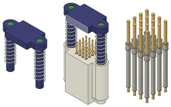
Figure 5.
Three-dimensional model of tactile feedback module.
- b.
- Control unit
The control unit and tactile feedback module of the wearable tactile reproduction device are two independent parts, as shown in Figure 6, where the design of the control unit’s servo compartment only needs to take into account the arrangement of the internal servo units to ensure that each individual servo is installed in a nuclear suitable location. In total, 18 U-shaped servo compartments are divided into a staggered arrangement according to 16 + 2, the size of the U-shaped servo compartment is slightly larger than the size of the servo, and the rectangular hole at the bottom is reserved for the servo drive cord to ensure the subsequent installation of the servo. The position of the outlet hole corresponds to the output end of each servo to ensure that there is no interference between each subsequent drive cable, and the four screw holes are reserved for connection with other parts.
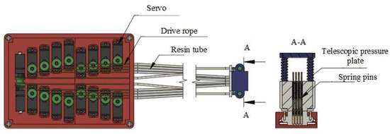
Figure 6.
Wearable tactile reproduction device.
The drive servo of the wearable tactile reproduction device is the HD-1370A miniature servo with a weight of 3.7 g and dimensions of mm. The servo comes with an encoder and the yellow, red, and brown servo control lines are the power, ground, and signal lines, respectively. Its rated torque is 0.4 kg-cm to 0.6 kg-cm; the corresponding rated voltage is 4.8–6.0 V, for the built-in motor reducer; the rotation angle is 0° to 180°, and it can maintain any angle within the effective rotation angle; and all the parameters meet the requirements of this device.
The output shaft of the servo is 4 mm in diameter, within its working stroke. The contraction length of the drive rope driven by the rotation of the output shaft is not enough to complete the contraction of the stylus and the telescopic pressure plate, so it is necessary to add a wire wheel to increase the rotation diameter of the servo shaft, so that the stylus can complete the complete contraction. A binding wire block is used to reduce the friction between the drive rope and the inner wall of the resin tube. The drive rope is connected to the servo and contact spring pin. The drive rope must be able to withstand a certain tension and will not demonstrate elastic stretching, to ensure the stability of the spring pin and the repeated movement of the expansion lever position, so we chose 0.4 size 8-braided PE cable. To enable the operator to better wear the tactile reproduction device, the slot is designed according to the average size of the human arm. The slot and the elastic harness cooperate to ensure that the tactile reproduction device will not fall off during use. The back cover is to protect the driver board of the servo from bumping.
2.3.1. Working Principle and Method
The wearable tactile reproduction device uses a composite dot-matrix mechanism to simulate the contact touch of virtual objects. Compared with the feedback device that reproduces the change in the appearance of virtual objects, an active actuator is added to provide pressure, and the squeezing pressure acts on the index finger. A set of reset springs set on the pressure plate telescopic column ensures that the pressure plate has sufficient return force and the contact sensation of the operator’s finger does not receive the influence of the fingertip position. Based on the composite point mechanism in this device, it can provide the contact simulation of a rigid object and flexible object at the fingertip. Firstly, in the state that the front servo unit and the rear servo unit are not working, the pressure plate is in the highest position and all the spring pins are in the lowest position. When the virtual hand touches the object and needs to generate tactile feedback, the front servo unit pulls the drive rope through the wire wheel to drive the pressure plate downward, and the rear servo unit loosens the drive rope through the wire wheel to make the ends of the spring pins stay at different heights.
When simulating contact with a rigid object, the rear servo unit loosens the drive rope through the wire wheel to make the end of the spring pin stay at different heights to reproduce the shape of the contact surface of the rigid object. And as the virtual hand squeezes the rigid object downward, the rear servo unit remains stationary, and the front servo unit pulls the drive rope through the wire wheel to drive the pressure plate downward to squeeze the fingertip to produce the contact force when squeezing. When simulating contact with a flexible object, the rear servo unit loosens the drive rope through the wire wheel to make the end of the spring pin stay at different heights to reproduce the shape of the contact surface of the rigid object. And as the virtual hand squeezes the flexible object downward, the rear servo unit loosens the drive rope as the appearance of the flexible object changes to make the end of the spring pin stay at a new position, and the front servo unit drives the lever downward through the spool to tighten the drive rope squeezing the fingertip to produce the contact force when squeezing.
2.3.2. System Theoretical Error Compensation
The height adjustment of the spring stylus is controlled by the servo, which is obtained by precise reciprocating rotation of the servo between 0 and 90°. The drive train model of a single spring stylus is shown in Figure 7. However, the transmission system and resin tube elasticity can produce errors in the displacement of the stylus. Therefore, the authors performed a detailed force analysis of the system and suppressed the system errors to ensure the accuracy of the servo motor output displacements. The default system is frictionless and the drive rope has a very low mass and no deformation.
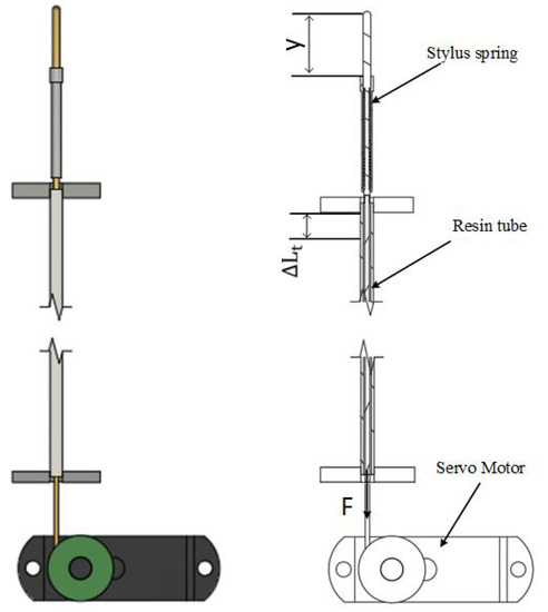
Figure 7.
Drive train model with a single spring stylus.
In this simplified system, y stands for the displacement of the stylus, stands for the elasticity of the resin tube under compressive load, and x stands for the input displacement of the drive rope (rotational displacement of the motor). Here, and represent the elastic constants of the stylus spring and the resin tube, respectively. Thus, when the stylus is fully stretched,
For the resin tube:
The rotational displacement of the servo x is equal to the sum of the displacements acting on the elastic components, as follows:
Bringing Equation (3) into Equation (4), the relationship between the displacement of the stylus and the displacement of the rudder can be defined as follows:
The formula is N/mm and N/mm.
Equation (5) can be written as . To construct the visualized behavior based on the response characteristics of the system, the authors rewrite the displacement of the input servo as a functional pattern , such that . Because the displacement of the stylus is linearly related to the input displacement of the servo, and the spring stylus is a reciprocating motion, the displacement of the stylus is always greater than 0. Assume the functional form is as follows:
where A is the displacement of the servo when it is rotated by 90° and T is the movement time of the servo from to rotation ( mm, s), which is determined by the model of the servo. When , the displacement of the stylus is required to be 0, so . Then, is obtained as
As can be seen from Figure 8, due to the elasticity of the resin tube and the spring stylus, there is a significant theoretical error between the displacement of the stylus and the input displacement of the servo. For the displacement error of the stylus, we can compensate it by using a linear static elasticity model. According to this model, we correct the input data of the servo by the inverse transfer function described in Equation (5) to reduce the theoretical error. The inverse transfer function converts the actual displacement of the stylus into the corresponding input displacement. By adding the inverse transfer function to the input data of the servo, the missing displacement of the stylus can be corrected to effectively reduce the theoretical error.
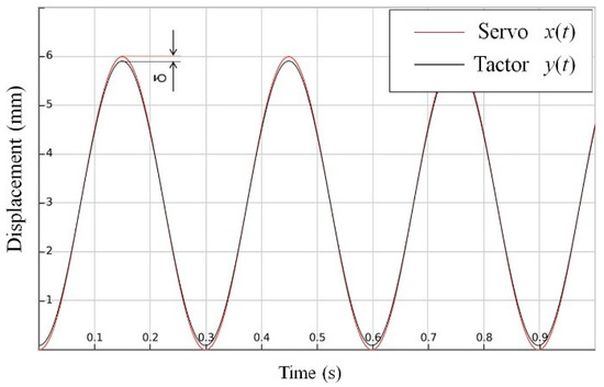
Figure 8.
Difference between servo and stylus displacement.
3. Design and Analysis of Kinesthetic Feedback Device
3.1. Design of Kinesthetic Feedback Device
The two main mobile joints of the human upper extremity structure are the shoulder and elbow joints, and the movement of the upper extremity is extremely complex. The shoulder joint is less constrained by the bones and is mainly constrained by the muscle groups in the shoulder; therefore, the motion of the shoulder joint is usually simplified to 3 degrees of freedom, flexion/extension, abduction/adduction, and rotation in/out. The elbow joint is a hinge joint with a complex axial displacement motion trajectory and a slight displacement of the rotation axis during flexion/extension motions, and its range of motion was determined according to the literature of Ham Yongwoon [37] and Vasen A.P. et al. [38] as shown in Table 2. Based on the motion characteristics of the human upper limb structure, the design of the wearable kinesthetic feedback device for the upper limb is determined.

Table 2.
Table of the range of motion of the main joints of the arm.
According to the design scheme, a wearable arm kinesthetic reproduction device is designed for kinesthetic feedback of a human arm. The wearable device is mainly used to transfer kinesthetic sensations such as displacement, velocity, and torque to the arm. The 3D model of the mechanical structure is shown in Figure 9. The device mainly consists of a base, an upper arm bracket, a flexible connector, a transition connector, and a forearm bracket. During operation, the upper arm and the forearm are placed inside the bracket and fixed by fastening straps and padding plates, and the inner side of the bracket is provided with a padding layer to increase the comfort of the user. Because the shoulder posture is rotated inward/outward, most of the weight of the whole upper arm is offset by the upper arm bracket and the base support, and the execution of the action relies on the rudder driven by the base mounted on the base. Elbow flexion and extension are driven by the rudder set on both sides of the upper arm bracket to increase the stability of operation. Reciprocating cycles within the safety angle are possible to meet the requirements for the use of kinesthetic feedback of the arm.
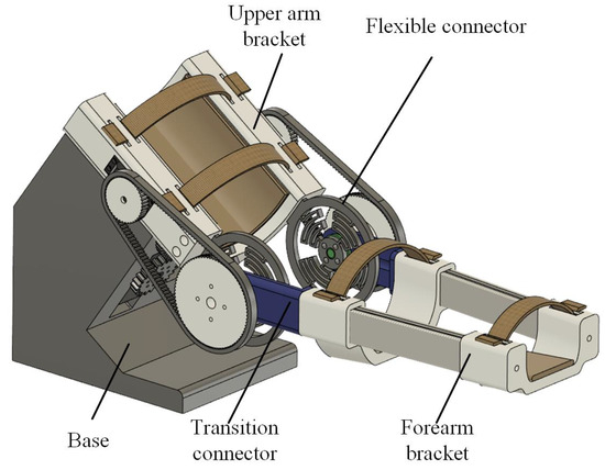
Figure 9.
Three-dimensional model of kinesthetic feedback device.
3.2. Simulation Analysis of Important Parts
The elbow joint of the exoskeleton uses a flexible joint whose elastic structure is symmetrically distributed to compensate for the axis deviation between the elbow joint and the exoskeleton during flexion and extension, which has three degrees of freedom in the plane and is connected to the transition joint through a connecting shaft and bearing, taking a passive adjustment for a more compact structure. The flexible module is calibrated by finite element software to verify the performance of its structure. The magnitude of the force applied in both the X and Y directions was 30 N [39], and when the flexible module is subjected to a force in the X direction, displacement and strain are generated, and its displacement in the X direction is 2.3198 mm and the maximum strain value is 0.002617, as shown in Figure 10. When the flexible module is subjected to a force in the Y direction, its displacement in the Y direction is 0.80245 mm and the maximum strain value is 0.00089533, as shown in Figure 11. The maximum displacement of the flexible module in both the X and Y directions is 2.3 mm, which can passively compensate for the axis deviation generated by the mechanical joint and the elbow joint of the arm to a certain extent, and the maximum strain values in the X and Y directions are in the safe range.
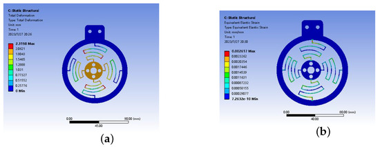
Figure 10.
Strain and displacement in X direction. (a) Displacement in X direction; (b) strain in X direction.
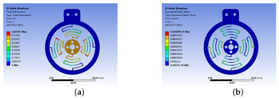
Figure 11.
Strain and displacement in Y direction. (a) Displacement in Y direction; (b) strain in Y direction.
3.3. Kinematic Analysis
To further illustrate the safety of the wearable kinesthetic feedback device for the upper extremity, a kinematic analysis of the device is performed using D-H analysis, as shown in Figure 12, where the D-H parameters are shown in Table 3.
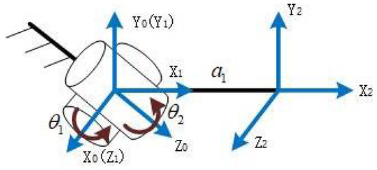
Figure 12.
D-H coordinates of wearable kinesthetic feedback device for upper limb.

Table 3.
Upper extremity wearable kinesthetic feedback device D-H parameters.
The positional matrix of the i bar of the adjacent coordinate system in the D-H coordinate system of the wearable kinesthetic feedback device for the upper extremity with respect to the bar is :
Then, the transformation matrix between the end coordinate system and the base coordinate system is shown in the following equation:
In the formula, indicates the pose of the second joint of the upper extremity wearable kinesthetic feedback device, and indicates the position of the end of the device relative to the base coordinate system.
To verify the kinematic equations, the simulation results of the upper limb wearable kinesthetic feedback device are obtained in MATLAB with = 90° and = 0° as the initial values as shown in Figure 13.
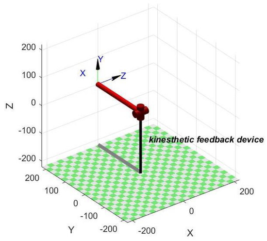
Figure 13.
Simulation analysis result of kinesthetic feedback device.
According to the designed upper limb wearable kinesthetic feedback device, the start joint variable and the end joint variable are set. The motion simulation is carried out through MATLAB, when the end of the upper limb wearable kinesthetic feedback device moves from the initial point to the termination point, and the angular displacement, angular velocity, and angular acceleration curves of each motion joint in the motion of the kinesthetic feedback device are shown in Figure 14. As can be seen from the figure, the completion time of the two joints is 5 s; the first joint, the flexion and extension of the elbow joint, moves from the initial position to 45°; the second joint, the internal and external rotation of the shoulder joint, moves from the initial position to 30°; and the movements of the first and second joints are completed at the same time. And the initial and termination velocities of the elbow joint and the shoulder joint are 0, and the acceleration at the initial and termination points are 0. The curves are smooth during the whole movement process. And the curve is smooth and continuous without mutation points during the whole movement process, which meets the stability and safety requirements of the upper limb exoskeleton mechanism movement.
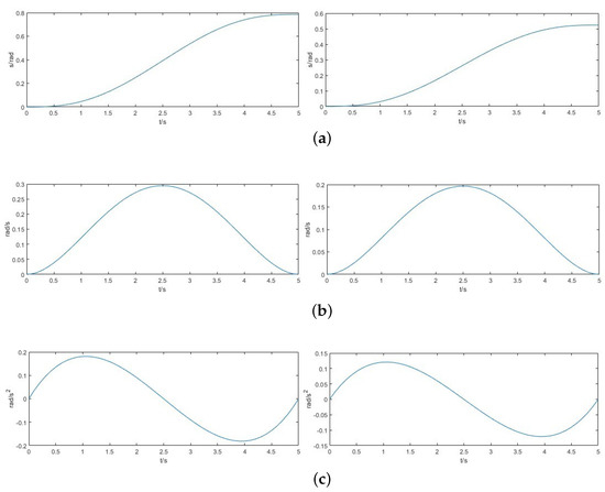
Figure 14.
Angular displacement, angular velocity, and angular acceleration graphs. (a) Angular displacement curve; (b) angular velocity curve; (c) angular acceleration curve.
4. Virtual Interaction Experiments
Based on the operation scenario of the PC, Leap Motion motion capture device, and kinesthetic–tactile feedback device, as shown in Figure 15, this experiment simulated the process of a blind person’s demonstration and teaching, in which the master operator (normal person) wore the kinesthetic gesture capture structure on the forearm, and the hand was located on the top of the Leap Motion motion capture device and manipulated the virtual hand to carry out the virtual interaction. The slave operator (blind person) wore a kinesthetic feedback device and a tactile feedback device on the arm and the tip of the index finger, respectively, and realized the positioning of the arm through the synchronized control of the kinesthetic feedback device, and then transmitted the tactile sensation to the blind person through the tactile feedback device.
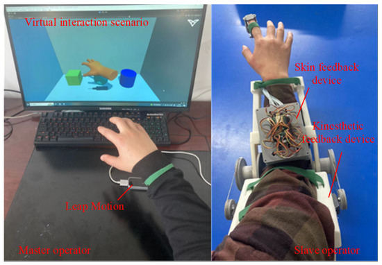
Figure 15.
Operation scenario diagram.
Experimental preparation included the following: (1) Eight volunteers, aged between 24 and 30 years, four females and four males, in good physical condition, with normal skin and soft tissues of the hand and normal tactile perception, were invited to participate in the actual experiment, all with right-handedness. And all the subjects understood the process and purpose of the experiment explicitly before the experiment, which was conducted after communication and confirmation. (2) Before the experiments were conducted, an introduction to the operating principles of the device was performed, as well as practice in the operation of the device. (3) Device commissioning was performed. The master operator interacted with the virtual scene, and the slave operator measured the overall system based on the tactile stimuli obtained from the kinesthetic–tactile feedback device, and the evaluation results were analyzed.
4.1. Virtual Object Shape Perception Experiment
The virtual object shape perception experiment evaluated the extent to which a kinesthetic–tactile fusion feedback system can render the surface of 3D objects (cubes, spheres, and cylinders). The virtual interaction scenario is shown in Figure 16. During the task, the Leap Motion was placed on a table in front of the master operator. The slave participant was asked to perform the perception of haptic feedback. The master operator took approximately 4 s to touch the specified target with the Leap Motion-controlled virtual hand during the target touch task, thus allowing 10 s to touch each object and at least 10 s for the slave participant to perform shape perception recognition. A total of 10 touches were performed for each type of virtual object.
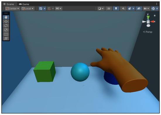
Figure 16.
Schematic diagram of virtual object shape perception experiment.
Experimental steps:
- (1)
- The slave operator performed shape observation of the virtual objects before the start of the experiment to ensure that the shape of the virtual objects could be judged during the experiment, as well as the positional arrangement of the three virtual objects;
- (2)
- The master operator manipulated the virtual hand to randomly touch a virtual object, and the slave operator wore a kinesthetic–tactile fusion feedback device to perceive the shape of the virtual object touched and recorded the time;
- (3)
- Within a predetermined time, the slave operator made a judgment on the shape of the virtual object based on the feedback haptic information from the kinesthetic–tactile fusion feedback device;
- (4)
- Each experiment was conducted 10 times for virtual object contact, and the roles of the master operator and the slave operator were swapped to repeat the experiment.
The judgment results of the virtual object perception experiments are shown in Table 4. The confusion rate of each of these objects is shown in Table 5.

Table 4.
Judgment rates of different virtual objects for virtual object shape perception experiments.

Table 5.
Confusion judgment table for different virtual objects.
From Table 4, it can be seen that the overall judgment rate of the cube is the highest for the slave operator, followed by a higher judgment success rate for the sphere than the cylinder. The main reason for the confusion in the shape judgment of the three virtual objects is the similarity of the local outer surface curvature of the cube, sphere, and cylinder and the difference in the location of contact and the degree of extrusion of the contact part when different master operators manipulate the virtual hand to make contact with the three virtual objects, as well as the difference in the individual haptic perception of different slave operators, which may produce misjudgment.
Figure 17 shows the tactile feedback module stylus state diagrams of, respectively, the object surface rendering and the user finger contact perception diagram with the stylus in interaction scene one.
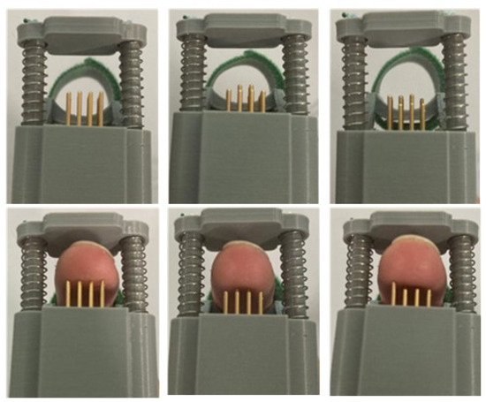
Figure 17.
Tactile feedback module stylus state diagram.
The top three figures in Figure 17 show the position of the stylus when the shape is reproduced by the fingertip feedback module. The three diagrams below show the fingertip contact perception diagram with the fingertip feedback module, from left to right, for the cube, sphere, and cylinder contact surface profiles, respectively, from which it can be seen that the height difference in the stylus position is obvious when reproducing different virtual object local profiles.
4.2. Object Elasticity Judgment Experiment
In the object elasticity judgment experiment, the slave operator judged the elasticity of the virtual interaction object of the master operator by wearing the kinesthetic–tactile fusion feedback device under the conditions of force feedback and without force feedback, respectively. The virtual interaction scenario of the object elasticity judgment experiment is shown in Figure 18. During the experiment, the slave operator needs to determine whether the cube was elastic or not and to judge its elasticity. Each master operator needed to complete elastic object presses a total of six times, in which the slave operator made judgments with and without force feedback, respectively. The judgment time of the slave operator in the experiment was recorded.
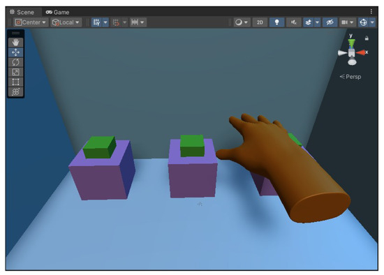
Figure 18.
Schematic diagram of object elasticity judgment experiment.
Experimental steps:
- (1)
- Each slave operator perceived the elasticity size of the virtual object under different force-feedback modes;
- (2)
- A specific experiment was conducted in which the master operator controlled the virtual hand to touch and press the square, and the slave operator made the judgment of the elasticity size under the conditions of force feedback and without force feedback. The cumulative judgment times under the conditions of force feedback and without force feedback were recorded separately, and the results are shown in Table 6 and Figure 19.
 Table 6. Schedule of judgment results of object elasticity judgment experiment.
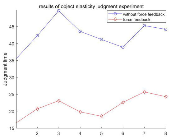 Figure 19. Results of object elasticity judgment experiment.
From the experimental data in the table above, it can be seen that the time to judge the elastic size of the three cubes varies between individuals. Using the comparative analysis method, by analyzing the comparison between the judgment time with and without force feedback, it was found that the judgment time of the elastic size of the three cubes was improved by at least 41.9% with the contact force provided by the force-feedback platen. The force feedback can improve the operator’s perceptual sensitivity.
Figure 20 shows the contact diagram between the fingertip and the tactile feedback module. The first column shows the initial state of the tactile feedback module, which can reveal the squeezing stroke of the telescopic platen; the second column shows that when there is no force sensory feedback, the fingertip judges the elasticity of the virtual object by sensing the displacement of the stylus of the tactile display module; and the third column shows that when there is force sensory feedback, the fingertip judges the elasticity of the virtual object by combining the displacement of the stylus of the tactile display module and the squeezing pressure prompt of the telescopic platen.
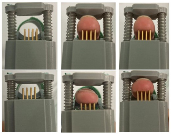
Figure 20.
Interaction scene schematic.
At the end of the experiment, participants were asked to answer a questionnaire including four questions using a 10-point scale, as shown in Table 7. The four questions consider comfort and wear resistance. A score of 1 indicates low perceived performance of the system (comfort or wear resistance), and a score of 10 indicates high performance.

Table 7.
Confusion judgment table for different virtual objects.
The results shown in Table 7 indicate that the device has good suitability, perceived performance, and wear resistance in terms of comfort and wear resistance and that the fatigue felt after the experiment may be caused by wearing the device for long interactions.
5. Conclusions and Discussion
Aiming at the problem that blind people cannot directly judge whether the objects they touch are dangerous or not through vision in the process of learning and cognition, this paper proposes a virtual reality-based kinesthetic–tactile fusion feedback system, which establishes kinesthetic–tactile fusion feedback through the mapping relationship between the master–slave and the virtual end, and it provides a possible scheme for the research of multimodal haptic feedback. By combining the tactile feedback technology, synchronized motion control system, motion capture system, and virtual reality technology, the synchronized control of the arm and the tactile feedback of the fingertip are realized to provide virtual haptic sensation for the blind group.
In order to evaluate the performance and applicability of the kinesthetic–tactile feedback device, the effectiveness of the device is evaluated by the master operator and the slave operator through virtual interaction experiments, aiming to enhance the haptic perception of the slave operator in multimodal haptic information feedback. The results show that the kinesthetic–tactile feedback device is able to provide more haptic perception information in virtual feedback and improve the recognition rate of haptic perception.
This fusion of a kinesthetic–tactile feedback device provides a more realistic experience for the user compared to a traditional single haptic feedback device. In addition, the wearing comfort of a haptic feedback device can also reduce unnecessary haptic information interference. Therefore, there is room to improve the haptic stimulation provided by the multimodal kinesthetic–tactile fusion feedback device, which is the focus of our future work, and we will further improve the degree of integration of the kinesthetic–tactile feedback device.
Author Contributions
Conceptualization, Z.Z. and Y.C.; methodology, M.X. and Z.Z.; theoretical analysis and validation, Z.Z., P.G., K.S. and M.X.; writing—original draft preparation, P.G. and K.S.; writing—review and editing, K.S., P.G., T.Z. and Z.Z.; funding acquisition, Z.Z. and Y.C. All authors have read and agreed to the published version of the manuscript.
Funding
This research was funded by Natural Science Foundation of Anhui Province (Grant No. 2108085QF278), the Innovation Project for Returned Overseas Students of Anhui Province (Grant No. 2020LCX013), Open Research Fund of Key Laboratory of Electric Drive and Control of Anhui Province (Grant No. DQKJ202208).
Informed Consent Statement
Informed consent was obtained from all subjects involved in the study; all the subjects understood the process and purpose of the experiment explicitly before the experiment.
Data Availability Statement
Not applicable.
Conflicts of Interest
The authors declare no conflict of interest.
References
- Carlos, B.; Pan, H. A Survey on Haptic Technologies for Mobile Augmented Reality. ACM Comput. Surv. 2021, 54, 1–35. [Google Scholar] [CrossRef]
- Sun, Z.; Zhu, M.; Shan, X.; Lee, C. Augmented tactile-perception and haptic-feedback rings as human-machine interfaces aiming for immersive interactions. Nat. Commun. 2022, 13, 5224. [Google Scholar] [CrossRef] [PubMed]
- Caeiro-Rodríguez, M.; Otero-González, I.; Mikic-Fonte, F.A.; Liamas-Nistal, M. A Systematic Review of Commercial Smart Gloves: Current Status and Applications. Sensors 2021, 21, 2667. [Google Scholar] [CrossRef]
- Guo, S.; Wang, Y.; Xiao, N.; Li, Y.; Jiang, Y. Study on real-time force feedback for a master–slave interventional surgical robotic system. Biomed. Microdevices 2018, 20, 37. [Google Scholar] [CrossRef]
- Jin, X.; Guo, S.; Guo, J.; Shi, P.; Tamiya, T.; Hirata, H. Development of a Tactile Sensing Robot-assisted System for Vascular Interventional Surgery. IEEE Sens. J. 2021, 21, 12284–12294. [Google Scholar] [CrossRef]
- Ozdemir, D.; Ozturk, F. The Investigation of Mobile Virtual Reality Application Instructional Content in Geography Education: Academic Achievement. Int. J. Human Comput. Interact. 2022, 38, 1487–1503. [Google Scholar] [CrossRef]
- Imran, E.; Adanir, N.; Khurshid, Z. Significance of Haptic and Virtual Reality Simulation (VRS) in the Dental Education: A Review of Literature. Appl. Sci. 2021, 11, 10196. [Google Scholar] [CrossRef]
- Grushko, S.; Vysocký, A.; Oščádal, P.; Vocetka, M.; Novák, P.; Bobovský, Z. Improved Mutual Understanding for Human-Robot Collaboration: Combining Human-Aware Motion Planning with Haptic Feedback Devices for Communicating Planned Trajectory. Sensors 2021, 21, 3673. [Google Scholar] [CrossRef] [PubMed]
- Ozioko, O.; Karipoth, P.; Escobedo, P.; Ntagios, M.; Pullanchiyodan, A.; Dahiya, R. SensAct: The soft and squishy tactile sensor with integrated flexible actuator. Adv. Intell. Syst. 2021, 3, 1900145. [Google Scholar] [CrossRef]
- Chen, S.; Chen, Y.; Yang, J.; Han, T.; Yao, S. Skin-integrated stretchable actuators toward skin-compatible haptic feedback and closed-loop human-machine interactions. NPJ Flex. Electron. 2023, 7, 1. [Google Scholar] [CrossRef]
- Chinello, F.; Pacchierotti, C.; Malvezzi, M.; Prattichizzo, D. A Three Revolute-Revolute-Spherical Wearable Fingertip Cutaneous Device for Stiffness Rendering. IEEE Trans. Haptics 2018, 11, 39–50. [Google Scholar] [CrossRef] [PubMed]
- Tang, Y.; Liu, S.; Deng, Y.; Zhang, Y.; Yin, L.; Zheng, W. Construction of force haptic reappearance system based on Geomagic Touch haptic device. Comput. Methods Programs Biomed. 2020, 190, 105344. [Google Scholar] [CrossRef] [PubMed]
- Yan, Y.; Wu, C.; Cao, Q.; Tang, D.; Fei, F.; Song, A. Design and implementation of a new tactile feedback device for arm force. Meas. Control Technol. 2020, 39, 36–40. [Google Scholar] [CrossRef]
- Mo, Y.; Song, A.; Qin, H. Design and evaluation of a finger-end wearable force-tactile interaction device. J. Instrum. 2019, 40, 161–168. [Google Scholar] [CrossRef]
- Pacchierotti, C.; Sinclair, S.; Solazzi, M.; Frisoli, A.; Hayward, V.; Prattichizzo, D. Wearable haptic systems for the fingertip and the hand: Taxonomy, review, and perspectives. IEEE Trans. Haptics 2017, 10, 580–600. [Google Scholar] [CrossRef] [PubMed]
- Talasaz, A.; Trejos, A.L.; Patel, R.V. The Role of Direct and Visual Force Feedback in Suturing Using a 7-DOF Dual-Arm Teleoperated System. IEEE Trans. Haptics 2017, 10, 276–287. [Google Scholar] [CrossRef] [PubMed]
- Jung, W.-J.; Kwak, K.-S.; Lim, S.-C. Vision-based suture tensile force estimation in robotic surgery. Sensors 2021, 21, 110. [Google Scholar] [CrossRef]
- Adilkhanov, A.; Yelenov, A.; Reddy, R.S.; Terekhov, A.; Kappassov, Z. VibeRo: Vibrotactile Stiffness Perception Interface for Virtual Reality. IEEE Robot. Autom. Lett. 2020, 5, 2785–2792. [Google Scholar] [CrossRef]
- Fu, Y.; Lin, W.; Yu, X.; Rodríguez-Andina, J.J.; Gao, H. Robot-Assisted Teleoperation Ultrasound System Based on Fusion of Augmented Reality and Predictive Force. IEEE Trans. Ind. Electron. 2023, 70, 7449–7456. [Google Scholar] [CrossRef]
- Lee, G.; Hur, S.M.; Oh, Y. High-Force Display Capability and Wide Workspace with a Novel Haptic Interface. IEEE/ASME Trans. Mechatron. 2017, 22, 138–148. [Google Scholar] [CrossRef]
- Moriyama, T.; Kajimoto, H. Wearable Haptic Device Presenting Sensations of Fingertips to the Forearm. IEEE Trans. Haptics 2022, 15, 91–96. [Google Scholar] [CrossRef] [PubMed]
- Michikawa, R.; Endo, T.; Matsuno, F. A Multi-DoF Exoskeleton Haptic Device for the Grasping of a Compliant Object Adapting to a User’s Motion Using Jamming Transitions. IEEE Trans. Robot. 2023, 39, 373–385. [Google Scholar] [CrossRef]
- Suchoski, J.M.; Barron, A.; Wu, C.; Quek, Z.F.; Keller, S.; Okamura, A.M. Comparison of kinesthetic and skin deformation feedback for mass rendering. In Proceedings of the 2016 IEEE International Conference on Robotics and Automation (ICRA), Stockholm, Sweden, 16–21 May 2016; pp. 4030–4035. [Google Scholar] [CrossRef]
- Gallo, S.; Santos-Carreras, L.; Rognini, G.; Hara, M.; Yamamoto, A.; Higuchi, T. Towards multimodal haptics for teleoperation: Design of a tactile thermal display. In Proceedings of the 2012 12th IEEE International Workshop on Advanced Motion Control (AMC), Sarajevo, Bosnia and Herzegovina, 25–27 March 2012; pp. 1–5. [Google Scholar] [CrossRef]
- Gao, B.; Gao, S.; Zhong, Y.; Hu, G.; Gu, C. Interacting multiple model estimation-based adaptive robust unscented Kalman filter. Int. J. Control Autom. Syst. 2017, 15, 2013–2025. [Google Scholar] [CrossRef]
- Gao, B.; Hu, G.; Zhong, Y.; Zhu, X. Cubature Kalman Filter With Both Adaptability and Robustness for Tightly-Coupled GNSS/INS Integration. IEEE Sens. J. 2021, 21, 14997–15011. [Google Scholar] [CrossRef]
- Koller, T.L.; Frese, U. The Interacting Multiple Model Filter and Smoother on Boxplus-Manifolds. Sensors 2021, 21, 4164. [Google Scholar] [CrossRef] [PubMed]
- Luo, S.; Mou, W.; Althoefer, K.; Liu, H. iCLAP: Shape recognition by combining proprioception and touch sensing. Auton Robot. 2019, 43, 993–1004. [Google Scholar] [CrossRef]
- Fan, L.; Song, A.; Zhang, H. Development of an Integrated Haptic Sensor System for Multimodal Human–Computer Interaction Using Ultrasonic Array and Cable Robot. IEEE Sens. J. 2022, 22, 4634–4643. [Google Scholar] [CrossRef]
- Kossowsky, H.; Farajian, M.; Nisky, I. The Effect of Kinesthetic and Artificial Tactile Noise and Variability on Stiffness Perception. IEEE Trans. Haptics 2022, 15, 351–362. [Google Scholar] [CrossRef]
- Pappalardo, A.; Albakri, A.; Liu, C.; Bascetta, L.; Momi, E.D.; Poignet, P. Hunt-Crossley Model Based Force Control For Minimally Invasive Robotic Surgery. Biomed. Signal Process. Control 2016, 29, 31–43. [Google Scholar] [CrossRef]
- Zhu, X.; Gao, B.; Zhong, Y.; Gu, C.; Choi, K. Extended Kalman filter for online soft tissue characterization based on Hunt-Crossley contact model. J. Mech. Behav. Biomed. Mater. 2021, 123, 104667. [Google Scholar] [CrossRef]
- Zhu, X.; Li, J.; Zhong, Y.; Choi, K.S.; Shirinzadeh, B.; Smith, J.; Gu, C. Iterative Kalman filter for biological tissue identification. Int. J. Robust Nonlinear Control 2023, 1–13. [Google Scholar] [CrossRef]
- Chinello, F.; Malvezzi, M.; Prattichizzo, D.; Pacchierotti, C. A Modular Wearable Finger Interface for Cutaneous and Kinesthetic Interaction: Control and Evaluation. IEEE Trans. Ind. Electron. 2020, 67, 706–716. [Google Scholar] [CrossRef]
- Somer, D.D.; Perić, D.; Neto, E.A.d.; Dettmer, W.G. A multi-scale computational assessment of channel gating assumptions within the Meissner corpuscle. J. Biomech. 2015, 48, 73–80. [Google Scholar] [CrossRef] [PubMed]
- Jung, Y.H.; Yoo, J.Y.; Vazquez-Guardado, A.; Kim, J.H.; Kim, J.T.; Luan, H.; Minsu, P.; Jaeman, L.; Hee-Sup, S.; Chun-Ju, S.; et al. A wireless haptic interface for programmable patterns of touch across large areas of the skin. Nat. Electron. 2022, 5, 374–385. [Google Scholar] [CrossRef]
- Ham, Y. Shoulder and Hip Joint Range of Motion in Normal Adults. Korean J. Phys. Ther. 1991, 3, 97–108. [Google Scholar]
- Vasen, A.P.; Lacey, S.H.; Keith, M.W. Functional range of motion of the elbow. J. Hand Surg. 1995, 20, 288–292. [Google Scholar] [CrossRef]
- Fang, L.; Zhou, S.; Wang, Y. A new design of variable stiffness joint structure. J. Northeast. Univ. (Nat. Sci. Ed.) 2017, 38, 1748–1753. [Google Scholar]
Disclaimer/Publisher’s Note: The statements, opinions and data contained in all publications are solely those of the individual author(s) and contributor(s) and not of MDPI and/or the editor(s). MDPI and/or the editor(s) disclaim responsibility for any injury to people or property resulting from any ideas, methods, instructions or products referred to in the content. |
© 2023 by the authors. Licensee MDPI, Basel, Switzerland. This article is an open access article distributed under the terms and conditions of the Creative Commons Attribution (CC BY) license (https://creativecommons.org/licenses/by/4.0/).