Abstract
Independent metering systems (IMSs) have been applied and researched in mobile machinery due to their advantages of reduced throttling energy losses and remarkable advances under negative load through decoupling actuator throttling control. Although IMSs have the control flexibility to deal with negative workloads, the control performance of the IMSs is challenged by uncertain loads in mobile operations, limiting the control accuracy. In addition, if the motion reference is improperly specified and exceeds the constraints, the pressure of the actuator may oscillate significantly and potentially result in control instability. In this study, a constrained adaptive robust control strategy is proposed for an IMS. An adaptive robust control strategy is designed for the meter-in and meter-out throttling to achieve precision motion control despite the nonlinearities and uncertainties of the electro-hydraulic IMS. The value of the uncertain workload is estimated in real-time and utilized in the model-based controller to improve control accuracy. In addition, a constrained trajectory planning approach is presented to handle out-of-constraint references and ensure motion tracking performance. This effectively prevents pressure fluctuations caused by the inappropriate reference.
1. Introduction
Independent metering systems (IMSs) can reduce throttling energy losses by independently controlling the metering at both ends of hydraulic actuators. Meanwhile, the decoupling of the actuator control provides control flexibility to deal with negative working loads. Due to the above advantages, independent metering systems have been applied and researched in mobile machinery [1], including in the fields of construction, agriculture, and forestry. In [2], a combination of an electro-hydraulic flow-on-demand system with independent metering of the actuators of a mobile forestry crane is proposed, achieving improved efficiency and controllability. In [3], a model-based precision motion control is proposed for an independent metering system of a hydraulic robotic manipulator, in which a separate meter-in and meter-out control of the actuator is realized by two 3/3 proportional valves.
Although IMSs have the flexibility to deal with negative loads, the control performance of the IMSs is challenged by uncertain loads in mobile operations. These uncertain loads can be time-varying and limit the high control accuracy. In addition, the tracking reference from the operator may not fully meet the constraints of the system [4]. If the given motion tracking reference exceeds the constraints, the pressure of the actuator may shift dramatically and negative phenomena such as pressure saturation, air suction, actuator oscillation or even control instability could occur. Moreover, inherent hydraulic nonlinearities and uncertainties are other issues limiting the control performance of the IMSs.
To deal with the control difficulty of the uncertain actuator disturbance, model-based control strategies with accurate plant analysis have been published and shown to be robust solutions. In [5], an adaptive fuzzy sliding mode controller is developed for the motion control of an electro-hydraulic actuator to deal with the time-varying and unknown dynamics. In [6], a disturbance rejection adaptive control approach is proposed for a motion control hydraulic system. The study carried out in [7] proposes a -based control method combined with feedforward to improve disturbance rejection for hydraulic mobile manipulators. In addition, adaptive robust control (ARC) has demonstrated excellent capabilities in managing nonlinear control challenges of hydraulic actuators. In [8], an ARC motion control is proposed for an independent metering system, achieving accurate control performance. In addition, ARC is used in [9] to deal with nonlinearities for pump control electro-hydraulic actuators. In [10], ARC effectively estimates uncertain negative loads of a hydraulic actuator, improving control accuracy and robustness. These adaptive robust controllers achieve guaranteed motion tracking precision and show a high level of capability in dealing with hydraulic dynamic nonlinearities and parametric uncertainties.
Constrained control of electro-hydraulic systems has received recent attention in the literature. The study carried out in [11] addressed joint constraints by deriving a gradient projection method with a weighted Jacobian matrix, which achieved flow optimization for a hydraulic manipulator with one degree of redundancy. Xu et al. [12] proposed a motion tracking controller that ensures non-violation of full-state constraints using a barrier Lyapunov function-based constraint control. In [13], an interaction force controller was introduced for a hydraulic exoskeleton, taking into account a holonomic wearer constraint incorporated into the system dynamics. In [14], a robust nonlinear control method for electro-hydraulic force control systems with output constraints was developed. In [15], a nonlinear model predictive control trajectory planner was introduced for linear motor systems with constraints. However, the industrial and mobile electro-hydraulic applications may face challenges due to the high computational requirements associated with online solvers such as MPC. Although these studies contribute to the field of constrained control for electro-hydraulic systems, there is still a lack of effective solutions to achieve optimal and robust constrained control performance in the context of independent metering systems (IMS) motion control.
To deal with the constraints of motion control, a nonlinear two-order filter for real-time trajectory scaling method was proposed in [16,17], which can plan a constrained trajectory in real time to robustly reach the reference while satisfying the velocity and acceleration constraints. In [18], a trajectory optimization-based adaptive robust motion control is proposed, achieving a minimum-time transient response and theoretically guaranteed stability. In [19], an integrated two-loop motion control strategy is proposed for a variable speed pump-controlled electro-hydraulic actuator, in which the nonlinear filter is used to synthesize a constrained optimal trajectory to handle the inappropriate references and the constraints of the pump control system are fully considered. The nonlinear filter-based trajectory planning strategy demonstrates promise in addressing constrained trajectory planning for IMSs.
This study proposes a constrained motion control of an IMS, in which a cylinder actuator is controlled by two 3/3 proportional valves. The contributions are summarized as follows: (1) An adaptive robust motion controller and a pressure controller are designed for the meter-in and meter-out sides, respectively, to accurately track a given trajectory despite the nonlinearities and uncertainties of the electro-hydraulic IMS. Particularly, the uncertain external workload value is estimated in real time. Its estimation is used in the model-based controller to improve the control accuracy. (2) To handle inappropriate tracking references, a constrained trajectory planning approach is presented. A constrained trajectory is synthesized to approach the original reference in the shortest time while satisfying the constraints. Thereby, sudden pressure variation and saturation caused by inappropriate references are effectively avoided. (3) Simulations are conducted under practical working conditions, using a validated nonlinear model of an IMS designed for a mobile forestry crane. Cases with representative operation conditions are performed. Motion tracking results with comparative controls demonstrate the advantages of the proposed constrained adaptive robust motion control strategy for IMSs.
Overall, this study contributes to the field of motion control in independent metering systems by addressing the challenges posed by uncertain loads and inappropriate tracking references. The proposed strategy offers improved control accuracy and stability, as demonstrated through simulations and comparative control results.
2. System Formulation and Modeling
In this section, an independent metering system is introduced, in which the meter-in and meter-out of the actuator are independently controlled by two proportional valves, respectively. As shown in the hydraulic schematic in Figure 1, the proportional valves are two three-position three-way proportional directional valves, connected to each side of the actuator, respectively. The high-order dynamic model of the mentioned IMS is detailed in this section, which mainly includes the dynamics of the actuator motion, pressure dynamics of each cylinder chamber, and flow rate functions of the proportional valve. Furthermore, considering the parametric uncertainties, a parameterized state-space model is formulated, which is used in the model-based control designed in Section 3.2.
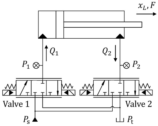
Figure 1.
Schematic of the IMS.
The actuator motion dynamics is modeled as
where m is the inertia load mass, is the position of the actuator, and represent the cylinder pressures, and are the areas of the two sides of the piston, b represents the viscous friction coefficient, and represents the lumped disturbance [20], and it also accounts for the external working load acting on the actuator.
The pressure dynamics can be described as
where and , and is the maximum stroke position. represents the effective bulk modulus.
The flow rate of the proportional valves is modeled as
with
where is the flow rate controlled by Valve i, is the model deviation of the flow rate, represents the pressure difference, represents the proportional input value for the valve spool position, and is a lumped proportional factor. In addition, and are the pump pressure and tank pressure, respectively.
The state variables of the independent metering control actuator are defined as . In addition, considering the uncertain parameters of the system, the uncertain parameters are defined as , in which .
The state-space dynamical model can be formulated as
where , representing a lumped nonlinear modeling error of F, and is the nominal value of F.
3. Constrained Nonlinear Motion Controller Design
In this section, an integrated constrained nonlinear motion controller is designed and presented to address the challenges associated with accurate motion control in independent metering systems (IMSs) operating under uncertain negative loads. The proposed controller takes into consideration the constraints, nonlinearities, and uncertainties inherent in the IMS, aiming to enhance control accuracy and stability.
The constraints of the hydraulic actuator motion control can be formulated by
where and are the preset upper and lower constraints of the velocity of the actuator. and are the upper and lower constraints of the acceleration of the actuator.
The structure of the developed controller, as shown in Figure 2, integrates two loops; (1) a constrained trajectory planning loop and (2) a model-based adaptive robust motion control loop [21]. The trajectory planning loop is responsible for generating motion references that adhere to the system constraints, ensuring safe and optimized motion tracking performance. This approach effectively prevents pressure variations caused by inappropriate reference inputs, which can lead to control instability. The model-based adaptive robust motion control loop utilizes an adaptive robust control strategy specifically designed for meter-in and meter-out throttling in the IMS. This strategy accounts for the system’s nonlinearities and uncertainties, allowing for precise motion control even in the presence of varying loads. Real-time estimation of the uncertain workload is incorporated into the model-based controller, thereby improving control accuracy by dynamically adjusting the control inputs. The designs of the two loops are detailed as follows.
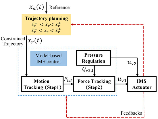
Figure 2.
Constrained IMS control structure.
3.1. Constrained Trajectory Planning
In this section, a constrained trajectory planning method is detailed for the motion tracking of the hydraulic actuator. A constrained trajectory is synthesized by a nonlinear filter to approach the original reference in the shortest time while satisfying the constraints. The nonlinear filter is designed with two integrators [16] as
where T denotes the sampling time, and j denotes the number of sampling periods (i.e., ).
The dynamics of the planned trajectory, i.e., the two-integrator chain (7), can be described by the following state equation:
where is the system state, and represents the the system input. Based on the two-integrator filter (7), and are given by
The error between the planned trajectory and the original desired reference is defined as y, can be expressed as
The error dynamics of the transformed system (10) is
where . Evidently, when the transformed system converges to the origin, the planned trajectory tends toward the given reference.
Furthermore, the following transformation is applied to isolate and from the sampling time T [17].
where
and . Matrix is nonsingular, implying an inverse transformation as below
Combining the transformed formulation (14) and the error dynamics (11), the following can be obtained
where
In the above formulation (15), the system state is transformed into an equivalent state .
To fulfill the time-optimal trajectory planning requirements, the control input of (15) is given by
where denotes a saturation function. Details of how is obtained are given in [16], and are omitted in this section.
As defined in Equation (11), the optimized acceleration of the trajectory can obtained by
The optimized position and velocity can be calculated through differential Equation (7). This constrained trajectory will be given to the motion controller as a motion tracking reference.
A theoretical proof of the trajectory planning strategy was rigorously performed in [16,17,22]. A sliding surface is created to force the system toward the origin and guarantee that robustly and optimally tracks .
3.2. Model-Based Adaptive Robust Motion Control for an IMS
An adaptive robust motion control strategy is designed for the IMS. As shown in Figure 2, a two-step motion controller and a pressure controller are designed for the Valve 1 and Valve 2, respectively.
3.2.1. Motion Control (Valve 1)
The motion of the actuator is controlled by Valve 1. An adaptive robust backstepping controller [9] is designed based on the high-order dynamics of the electro-hydraulic IMS, including a motion tracking step and force tracking step. and are defined as the estimation and estimation error of , respectively (i.e., ). The uncertain parameters are bounded by and . The adaptation law is given by
where is a diagonal adaptation matrix, is an adaptation function, is a discontinuous projection [23].
Step 1 (Motion tracking):
The flow rate to the left chamber (i.e., head chamber) is controlled by Valve 1. The position tracking error is defined as . The control goal is minimizing ; thereby, is defined as
where is the planned constrained trajectory, and is a positive feedback gain.
is defined as the hydraulic force on cylinder, modeled as
Then, the error dynamics are given as
The control input for Step 1 is defined as , and the control law is given as
where is a model compensation term, is a feedback term, is a positive feedback gain, and satisfies
with and can be arbitrarily small. The adaptation function of Step 1 is
Step 2 (Force tracking):
The error is defined as . To make converge to zero, the flow rate of Valve 1 (i.e., ) is defined as the control input of Step 2. The error dynamics are
where is a calculable part and is an uncalculable part.
The adaptive robust control input is designed as
where is a feedback gain, and the nonlinear robust feedback satisfies
with .
The adaptation function is designed as
where is
3.2.2. Pressure Regulation (Valve 2)
The pressure of the rod chamber is controlled by Valve 2. A desired pressure is generated for maintaining the left chamber pressure not lower than a preset minimum working pressure .
According to the desired hydraulic force designed in Equation (23) and hydraulic force equation , is given by
Furthermore, an adaptive pressure tracking controller is designed to accurately track the . The uncertain parameter set is defined as in which and . The pressure tracking error is defined as and its dynamics are given as
is defined as the control input that is designed as
where represents a model compensation term, represents the robust feedback term, and a positive stabilizing feedback gain. represents a robust feedback term, and it satisfies
The adaptation function and regression are designed as
The valve i (i = 1, 2) voltage input can be reversely calculated through Equation (3), and be given as
The theoretical control performance is rigorously proved with Lyapunov functions [24]. The whole closed-loop motion control is stable and the tracking error is bounded. In addition, asymptotic motion tracking ( as ) can be achieved in the presence of only parameter uncertainty.
In summary, the constrained motion tracking controller demonstrates robust control performance for a single actuator IMS system. It is worth noting that for systems with multiple degrees of freedom and different kinematic structures, it is important to consider the coupling among each actuator to achieve the overall control objective of the system.
4. Simulation
Comparative simulations using a validated nonlinear model of an IMS, as presented in Figure 1, are conducted via Matlab Simulink. The dynamic characteristics of the IMS, which are described in detail in Section 2, are implemented programmatically to accurately capture the system’s behavior. This modeling approach allows for addressing the control challenges associated with high-order dynamics, time-varying disturbances, and nonlinearities. By simulating the IMS under various scenarios, the performance of different control strategies can be evaluated and compared. The diameters of the actuator’s chamber and rod are 90 cm and 64.8 cm, respectively. The mass is set to 400 kg.
The sampling frequency is set at 200 Hz, which is achievable in industrial applications and meets the requirements for motion control. The computational requirements for the proposed control algorithm, which includes constrained trajectory planning and nonlinear motion control, is realistic and evaluated by numerical solutions. Therefore, the control strategy is well suited for implementation on embedded control devices, such as mobile machines, ensuring efficient and effective motion control in real-world applications.
The following comparative control strategies are chosen to verify the benefits of the proposed constrained control strategy.
- C1: Constrained adaptive robust controller (as shown in Figure 2).
- C2: Constrained deterministic robust controller. The motion tracking control is achieved by a model-based controller without parameter adaptation (i.e., no workload adaptation).
- C3: Model-based adaptive robust controller without constrained trajectory planning.
In the field of hydraulic motion control, achieving both high tracking accuracy and effective constrained trajectory planning is crucial for enhancing control performance in practical applications. However, only a limited number of existing studies have successfully addressed both control objectives simultaneously. Therefore, in the comparative verification section of the study, the proposed control strategy (referred to as C1) is compared with two typical approaches, namely C2 and C3, to highlight their respective advantages.
Specifically, C2 represents a nonlinear model-based backstepping controller that is renowned for its robust control performance in high-order systems. On the other hand, C3 is a model-based adaptive robust controller that has been effectively applied for precise control of hydraulic actuators [8,9]. Through these comparisons, the aim is to showcase the specific strengths of the proposed approach. The comparison between C1 and C2 demonstrates the advantage of workload adaptation present in C1. Similarly, the comparison between C1 and C3 highlights the superiority of the constrained trajectory planning aspect of C1, particularly when dealing with improper tracking references that exceed the predefined constraints.
The constraints (6) are assigned by
Cases with representative operation conditions are performed as follows.
4.1. Case 1
In Case 1, the working condition is designed considering a mobile forestry crane, in which a constant external force load of 32 kN occurs at time = 2 s to the actuator. This working circumstance is intended to simplify the mass load on the boom cylinder of the forestry crane during transporting of a log, which is introduced in [25]. The tracking reference in this study is a forth-and-back trajectory that simulates the motion of the boom cylinder for transporting a log from position 2 to position 3, as shown in Figure 3.
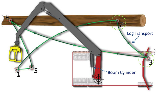
Figure 3.
A sample of forestry crane duty cycle [25] in Case 1.
The reference trajectory , the position tracking results , and tracking errors of C1 and C2 are presented in Figure 4. It shows that the uncertain external force load has the same influence on the starting of the transients (i.e., t = 2 s) of both controllers. In contrast, C1’s tracking error quickly converges to zero, and remains low throughout the subsequent transient. This is as a result of the adaptation of the disturbance defined in the actuator motion dynamics (1).
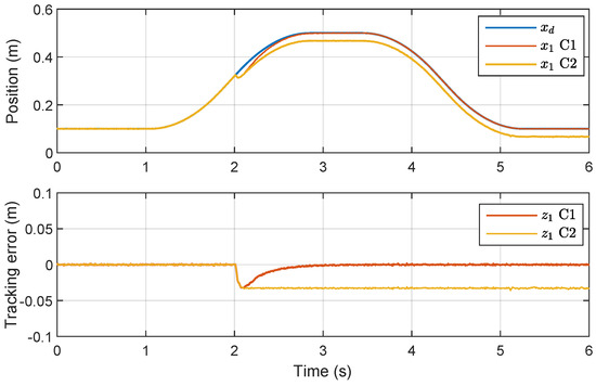
Figure 4.
Position tracking results in Case 1.
During the time interval from s to s, the actuator is subjected to a negative load, where the direction of the load is aligned with the desired direction of motion. Remarkably, the tracking results show that C1 achieved a high level of tracking accuracy, which can be attributed to the effective compensation of the disturbance model for the independent metering control of the actuator.
As shown in Figure 5, the real-time adaptation law (19) is used to update and minimize the tracking error by adjusting the estimation of the external force load in real time. The estimated value of the disturbance converges to the true value in about 1 s. This estimation is subsequently used in the model compensation process to further improve tracking accuracy.
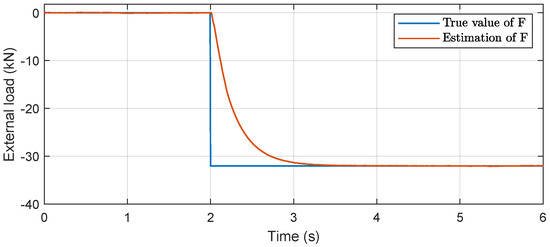
Figure 5.
Force load real-time estimation result.
The application of the adaptation law in conjunction with model compensation enables C1 to effectively compensate for the negative load disturbance, resulting in improved tracking accuracy. The ability to adapt to real-time changes and dynamically compensate for disturbances is a significant advantage of the proposed control strategy, which ultimately contributes to improved control performance in IMSs.
4.2. Case 2
In practical scenarios, the control performance of IMSs can be challenged by rapid actuator deceleration, leading to the occurrence of negative loads due to inertia. This situation may arise due to various factors, such as an improperly specified reference from the operator or programming errors.
To simulate and investigate this challenging working condition, a trajectory with jumping velocity is employed as the desired tracking reference. This trajectory deliberately introduces sudden changes in velocity, mimicking the scenarios where rapid actuator deceleration occurs. By utilizing this type of reference, the constrained control system can be tested and evaluated under practical conditions that pose difficulties for achieving accurate and stable motion control in IMSs.
The desired reference and position tracking results of C1 and C3 are presented in Figure 6. It shows that the given trajectory contains considerable dithers at time t = 1.8 s and t = 4.6 s. These abrupt variations in velocity can be regarded as unknown disturbances that challenge motion tracking performance. The velocity of the given reference , the synthesized constrained velocity of C1, and actual velocities of C1 and C3 are presented in Figure 7. It shows that a new constrained trajectory is synthesized to approach the desired reference while fulfilling the constraints (37). The dither of the velocity is prevented by the constrained trajectory given to the motion tracking controller.
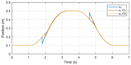
Figure 6.
Position tracking results in Case 2.
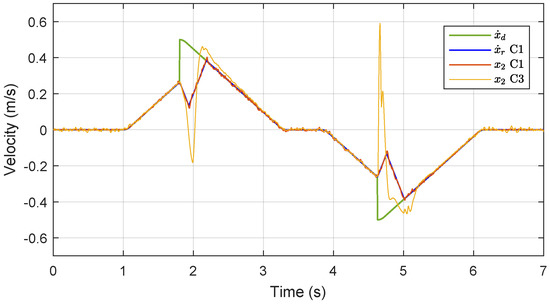
Figure 7.
Velocities in Case 2.
The pressure in each chamber of the actuator of C1 and C3 are shown in Figure 8. The pressures of C3 vibrate significantly during the switching of the velocity due to the tracking of a discontinuous velocity. This issue is effectively handled by the proposed constrained controller. Consequently, sudden pressure variation and saturation caused by the inappropriate reference are effectively avoided during the motion tracking of C1.
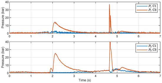
Figure 8.
Pressures in Case 2.
4.3. Case 3
This case is specifically designed to assess the capabilities of a constrained controller in handling situations where the tracking reference exceeds the velocity constraint. The desired tracking trajectory involves a point-to-point reference with a maximum velocity of 0.6 m/s, which surpasses the predefined velocity constraint of 0.5 m/s.
The position tracking results in Case 3 are illustrated in Figure 9. It can be observed that C1 achieved the same steady-state tracking accuracy as C3 by employing a different transient behavior that accurately followed the constrained trajectory to satisfy the constraints. Furthermore, Figure 10 demonstrates that the velocity of C1 remained within the predefined constraints while the constrained trajectory efficiently reached the reference point in minimum time.
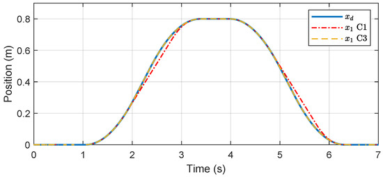
Figure 9.
Position tracking results in Case 3.
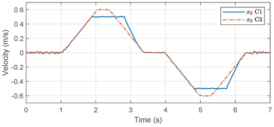
Figure 10.
Velocities in Case 3.
5. Conclusions
In this study, a constrained motion control strategy for an independent metering system is proposed to deal with uncertain loads. An adaptive robust motion controller and a pressure controller are constructed for the meter-in and meter-out sides. The value of the uncertain load is estimated in real time and compensated in the model-based controller to improve the control accuracy. In addition, a constrained trajectory planning approach is presented to deal with the tracking references beyond constraints and to further guarantee robustness. Simulations using a validated nonlinear model of an IMS are conducted with the consideration of practical working conditions of a mobile forestry crane. Typical cases under representative operating conditions are performed to validate the proposed constrained adaptive robust motion control. The results demonstrate that the proposed controller can effectively deal with the uncertain load. Moreover, a constrained trajectory is synthesized to approach the original reference in the shortest time while satisfying the constraints. Consequently, sudden pressure variation and saturation caused by the inappropriate reference are effectively prevented.
In the future, the proposed constrained control strategy will be implemented and tested on a real-world testbench. The constrained controller will be designed with consideration of additional realistic conditions, such as flow rate saturation and dynamic coupling constraints between multiple joint actuators.
Author Contributions
Conceptualization, B.H. and M.G.; methodology, B.H.; software, B.H.; validation, B.H.; investigation, B.H. and M.W.; resources, B.H. and M.W.; data curation, B.H.; writing—original draft preparation, B.H.; writing—review and editing, B.H., M.W. and M.G.; visualization, B.H.; supervision, M.G.; project administration, M.G.; funding acquisition, B.H. and M.G. All authors have read and agreed to the published version of the manuscript.
Funding
This work is funded by Open Foundation of the State Key Laboratory of Fluid Power and Mechatronic Systems under Grant GZKF-202202.
Data Availability Statement
Data sharing not applicable.
Conflicts of Interest
The authors declare no conflict of interest. The funders had no role in the design of the study; in the collection, analyses, or interpretation of data; in the writing of the manuscript; or in the decision to publish the results.
Abbreviations
| Symbol | Denotation |
| Actual trajectory of the actuator | |
| Desired trajectory | |
| Constrained trajectory | |
| y | Error for trajectory planning |
| Transformation of y | |
| Defined uncertain parameters | |
| Adaptation function | |
| Position tracking error | |
| Pressure tracking error | |
| F | Lumped disturbance on cylinder |
| Hydraulic force on cylinder | |
| Desired hydraulic force | |
| Pressure of the two cylinder chambers | |
| Areas of the two sides of the cylinder piston | |
| Flow rate of valve i, where | |
| Control input to valve i | |
| Pressures of the pump and tank |
References
- Geimer, M. Mobile Working Machines; SAE International: Warrendale, PA, USA, 2020. [Google Scholar] [CrossRef]
- Wydra, M.; Geimer, M.; Weiß, B. An approach to combine an independent metering system with an electro-hydraulic flow-on-demand hybrid-system. In Proceedings of the 15th Scandinavian International Conference on Fluid Power, Linköping, Sweden, 7–9 June 2017; Linköping University Electronic Press: Linköping, Sweden, 2017; pp. 161–170. [Google Scholar] [CrossRef]
- Koivumäki, J.; Zhu, W.H.; Mattila, J. Energy-efficient and high-precision control of hydraulic robots. Control Eng. Pract. 2019, 85, 176–193. [Google Scholar] [CrossRef]
- Zhang, F.; Zhang, J.; Cheng, M.; Xu, B. A Flow-Limited Rate Control Scheme for the Master–Slave Hydraulic Manipulator. IEEE Trans. Ind. Electron. 2022, 69, 4988–4998. [Google Scholar] [CrossRef]
- Tho, N.H.; Phuong, V.N.Y.; Danh, L.T. Development of an Adaptive Fuzzy Sliding Mode Controller of an Electrohydraulic Actuator Based on a Virtual Prototyping. Actuators 2023, 12, 258. [Google Scholar] [CrossRef]
- Yao, J.; Deng, W. Active disturbance rejection adaptive control of hydraulic servo systems. IEEE Trans. Ind. Electron. 2017, 64, 8023–8032. [Google Scholar] [CrossRef]
- Rigotti-Thompson, M.; Torres-Torriti, M.; Auat Cheein, F.A.; Troni, G. H∞-Based Terrain Disturbance Rejection for Hydraulically Actuated Mobile Manipulators with a Nonrigid Link. IEEE/ASME Trans. Mechatron. 2020, 25, 2523–2533. [Google Scholar] [CrossRef]
- Lyu, L.; Chen, Z.; Yao, B. Advanced Valves and Pump Coordinated Hydraulic Control Design to Simultaneously Achieve High Accuracy and High Efficiency. IEEE Trans. Control Syst. Technol. 2021, 29, 236–248. [Google Scholar] [CrossRef]
- Helian, B.; Chen, Z.; Yao, B.; Lyu, L.; Li, C. Accurate Motion Control of a Direct-Drive Hydraulic System with an Adaptive Nonlinear Pump Flow Compensation. IEEE/ASME Trans. Mechatron. 2021, 26, 2593–2603. [Google Scholar] [CrossRef]
- Helian, B.; Chen, Z.; Yao, B. Energy-saving and accurate motion control of a hydraulic actuator with uncertain negative loads. Chin. J. Aeronaut. 2021, 34, 253–264. [Google Scholar] [CrossRef]
- Li, L.; Cheng, M.; Ding, R.; Zhang, J.; Xu, B. Real-Time Flow Optimization of Hydraulic Manipulator with One Degree of Redundancy Considering Joint Limit Constraint. In Proceedings of the Fluid Power Systems Technology, ASME/BATH 2021 Symposium on Fluid Power and Motion Control, Virtual, 19–22 October 2021. [Google Scholar] [CrossRef]
- Xu, Z.; Qi, G.; Liu, Q.; Yao, J. ESO-based adaptive full state constraint control of uncertain systems and its application to hydraulic servo systems. Mech. Syst. Signal Process. 2022, 167, 108560. [Google Scholar] [CrossRef]
- Chen, S.; Han, T.; Dong, F.; Lu, L.; Liu, H.; Tian, X.; Han, J. Precision Interaction Force Control of an Underactuated Hydraulic Stance Leg Exoskeleton Considering the Constraint from the Wearer. Machines 2021, 9, 96. [Google Scholar] [CrossRef]
- Zang, W.; Zhang, Q.; Su, J.; Feng, L. Robust Nonlinear Control Scheme for Electro-Hydraulic Force Tracking Control with Time-Varying Output Constraint. Symmetry 2021, 13, 2074. [Google Scholar] [CrossRef]
- Liu, X.; Chen, Z.; Liu, Y.; Duan, F.; Yang, C.; Yao, B. Direct Optimization Based Compensation Adaptive Robust Control of Nonlinear Systems with State and Input Constraints. IEEE Trans. Ind. Inform. 2021, 17, 5441–5449. [Google Scholar] [CrossRef]
- Gerelli, O.; Lo Bianco, C.G. Nonlinear Variable Structure Filter for the Online Trajectory Scaling. IEEE Trans. Ind. Electron. 2009, 56, 3921–3930. [Google Scholar] [CrossRef]
- Lo Bianco, C.G.; Wahl, F.M. A novel second order filter for the real-time trajectory scaling. In Proceedings of the 2011 IEEE International Conference on Robotics and Automation, Shanghai, China, 9–13 May 2011; pp. 5813–5818. [Google Scholar] [CrossRef]
- Yuan, M.; Zhang, X. Stability and Fast Transient Performance Oriented Motion Control of a Direct-Drive System with Modeling Uncertainties, Velocity, and Input Constraints. IEEE/ASME Trans. Mechatron. 2022, 27, 5926–5935. [Google Scholar] [CrossRef]
- Helian, B.; Chen, Z.; Yao, B. Constrained Motion Control of an Electro-Hydraulic Actuator under Multiple Time-Varying Constraints. IEEE Trans. Ind. Inform. 2023, 1–11. [Google Scholar] [CrossRef]
- Wang, B.L.; Cai, Y.; Song, J.C.; Liang, Q.K. A Singular Perturbation Theory-Based Composite Control Design for a Pump-Controlled Hydraulic Actuator with Position Tracking Error Constraint. Actuators 2023, 12, 265. [Google Scholar] [CrossRef]
- Chen, Z.; Helian, B.; Zhou, Y.; Geimer, M. An Integrated Trajectory Planning and Motion Control Strategy of a Variable Rotational Speed Pump-Controlled Electro-Hydraulic Actuator. IEEE/ASME Trans. Mechatron. 2022, 28, 588–597. [Google Scholar] [CrossRef]
- Yuan, M.; Chen, Z.; Yao, B.; Liu, X. Fast and Accurate Motion Tracking of a Linear Motor System under Kinematic and Dynamic Constraints: An Integrated Planning and Control Approach. IEEE Trans. Control Syst. Technol. 2021, 29, 804–811. [Google Scholar] [CrossRef]
- Helian, B.; Mustalahti, P.; Mattila, J.; Chen, Z.; Yao, B. Adaptive robust pressure control of variable displacement axial piston pumps with a modified reduced-order dynamic model. Mechatronics 2022, 87, 102879. [Google Scholar] [CrossRef]
- Lyu, L.; Chen, Z.; Yao, B. Development of Pump and Valves Combined Hydraulic System for Both High Tracking Precision and High Energy Efficiency. IEEE Trans. Ind. Electron. 2019, 66, 7189–7198. [Google Scholar] [CrossRef]
- Scherer, M.; Geimer, M.; Weiß, B. Contribution on control strategies of flow-on-demand hydraulic circuits. In Proceedings of the 13th Scandinavian International Conference on Fluid Power, Linköping, Sweden, 3–5 June 2013; Linköping University Electronic Press: Linköping, Sweden, 2013; pp. 531–540. [Google Scholar] [CrossRef]
Disclaimer/Publisher’s Note: The statements, opinions and data contained in all publications are solely those of the individual author(s) and contributor(s) and not of MDPI and/or the editor(s). MDPI and/or the editor(s) disclaim responsibility for any injury to people or property resulting from any ideas, methods, instructions or products referred to in the content. |
© 2023 by the authors. Licensee MDPI, Basel, Switzerland. This article is an open access article distributed under the terms and conditions of the Creative Commons Attribution (CC BY) license (https://creativecommons.org/licenses/by/4.0/).