Abstract
At present, the positioning control of the hydraulic support pushing systems in fully mechanized mining faces uses an electrohydraulic directional valve as the control component, while the current research mainly focuses on servo valves, proportional valves, high−speed on−off valves, and electromagnetic directional valves. At present, the positioning control for electrohydraulic directional valves is only a simple logical control. Therefore, in order to improve the positioning control accuracy of the hydraulic support pushing system, a predictive positioning control strategy based on iterative learning was designed. Firstly, mathematical modeling of the hydraulic support pulling process was carried out, and its state−space equation was established. Secondly, an iterative learning controller with a state observer was designed, in which the iterative learning method was used to predict the control advance in the positioning process, and the state observer was used to estimate the parameters that could not be measured by the system, so as to improve the control accuracy in the broaching process. Then, a SimulationX–Simulink joint simulation model of the position control system of a multi−cylinder pulling hydraulic support was built, and the designed iterative learning controller was compared with the BP neural network controller. Finally, a test platform for the hydraulic support pushing system was built, and the proposed control strategy was experimentally verified. The research results show that the iterative learning control strategy proposed for the electrohydraulic directional valve not only simplifies the design process of the controller but also has higher positioning control accuracy. The single−cylinder positioning control accuracy can be controlled within 10 mm, and the multi−cylinder coordinated positioning control accuracy can be controlled within 15 mm, which meets the accuracy requirements of the site.
1. Introduction
The intelligentization of coal mining face equipment is an effective way to achieve safe and efficient development of coal resources. Being among the key equipment for mechanized mining of fully mechanized mining faces, hydraulic supports are mainly responsible for the safe support of goaf roofs and the scraper conveyor. Fully mechanized working faces require that the straightening error of the whole hydraulic support group is less than 200 mm, and that the straightening error between adjacent supports is less than 50 mm. However, the complex environment of the fully mechanized working face makes it very difficult to control the position of the pushing cylinder, and with the current technical level it is difficult to meet the requirements [1,2]. Today, most coal mine sites still use manual rope−pulling or infrared beams as reference lines and then adjust them through simple logical control of electrohydraulic directional valves. Obviously, these methods cannot meet the requirements of automation in fully mechanized mining faces and the positional accuracy of hydraulic supports, greatly affecting the efficiency and safety of coal mining [3,4].
At present, research on the straightness of fully mechanized mining faces mainly focuses on two aspects: the control of the hydraulic support pushing system, and the measurement and perception technology of the working face’s equipment status. The essence of positioning control for hydraulic support pushing systems is to improve the position control accuracy of valve-controlled cylinder systems in a coal mine environment. Therefore, current research methods in valve−controlled cylinder position control can be referenced. Jin et al. [5] proposed a learning algorithm based on the switching law of future state prediction and the prediction model needed for online learning for a hydraulic cylinder controlled by an electromagnetic switch direction control valve, and they verified the control scheme through physical experiments. Yang et al. [6] combined bang–bang control with PFM control for the hydraulic cylinder position control system of an electromagnetic directional valve, and they verified the effectiveness of this control method through joint simulation. Wang et al. [7,8] designed a Levant differentiator and an extended disturbance observer to estimate the output parameters and total disturbance of the system, and they introduced the obstacle Lyapunov function to prove the stability of the closed−loop system. In order to improve the tracking accuracy of a valve-controlled hydraulic system, Wang et al. [9,10,11,12] designed a controller combined with an intelligent control algorithm and verified the effectiveness of the designed controller by simulation and experiment. In order to solve the problems of slow response, poor precision, and weak anti−interference ability in hydraulic servo position controls, Guo et al. [13] designed a Kalman genetic optimization PID controller. The nonlinear characteristics of the pneumatic servo system were the main factors limiting its control accuracy. Zhang et al. [14] proposed a new mathematical model of the nonlinear system of the valve control cylinder to improve the control accuracy of the pneumatic servo system. Regarding the perception technology for measuring the status of workface equipment, Wang et al. [15] proposed a method for measuring the motion distance of hydraulic supports based on machine vision, and they obtained good measurement results in the experimental stage. Wang et al. [16] proposed a point−cloud−based hydraulic support group height and straightness measurement method to solve the shortcomings of the current measurement method for measuring the attitude and straightness of the hydraulic support group. Australia [17,18], Germany [19], the United States [20,21], and other countries made significant progress in implementing inertial−navigation−based measurement, control, and alignment positioning systems for work surfaces in the mid−1990s—especially LASC technology. In addition, in recent years, digital twins [22] and signal processing technologies have also made rapid development in the straightness control of fully mechanized mining faces.
Although there have been many studies on the measurement and perception technology of the working face’s equipment status, the final straightening of the working face still relies on the positioning control of the hydraulic support’s pushing oil cylinder, which is the control actuator. Due to the actual working conditions of high pressure, large flow, and high−water base underground, the electrohydraulic directional valve is still used as the control component. However, there is currently limited research on the valve-controlled cylinder position control strategy for electrohydraulic directional valves, and there is a lack of research on the multi−cylinder collaborative work control method during the bracket−pulling process.
As the control center in the positioning process of the hydraulic support, the electrohydraulic directional valve has the characteristics of low switching frequency, delay, etc. How to maintain the control accuracy of the electrohydraulic directional valve under the high−pressure, large−flow, and high−water−base conditions is the key problem to be solved in this paper. In order to improve the position accuracy of the oil cylinder of the hydraulic support in the fully mechanized mining face, we designed a prediction−based positioning control method composed of a state observer and an iterative learning controller. The state observer estimates the parameters that the system cannot measure, and the iterative learning controller is used to predict the advance of the oil cylinder’s position. The valve−controlled cylinder control method based on prediction in this paper not only improves the control accuracy of the valve−controlled cylinder system in the drawing process, it also simplifies the design process of the controller.
2. Modeling of the Hydraulic Support Pushing System
The arrangement of the hydraulic support’s pushing oil cylinders can be divided into two types: forward installation and reverse installation. When installed in the forward direction, the extension and retraction of the pushing oil cylinders correspond to the sliding and pulling movements, respectively; When installed in reverse, the extension and retraction of the pushing oil cylinders correspond to the pulling support and sliding action, respectively. The reverse installation method is shown in Figure 1. For the convenience of research, we took the ZY 8000/25/50 (S) D−type shield hydraulic support of thin coal seams as the research object and conducted force analysis on the front−mounted pushing oil cylinder.
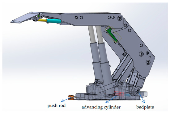
Figure 1.
Figure 1. Arrangement of pushing oil cylinder.
Taking pulling as an example for force analysis, the hydraulic support is moved forward as a whole by pushing the oil cylinder based on the middle groove of the scraper conveyor. The force analysis of the hydraulic support is shown in Figure 2. At this time, the force can be expressed as follows [23]:
where is the overall weight of the support, is the acceleration, is the area of the piston chamber of the pushing cylinder, is the area of the rod cavity of the pushing cylinder, and are the pressures corresponding to the piston chamber and the rod chamber, respectively, and is the friction force of the hydraulic support when the support is pulled, which can be further expressed as follows:
where is the friction coefficient of the support pulling process; due to the complex ground environment of the working face, the value of is not fixed.
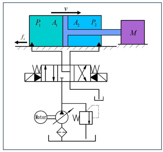
Figure 2.
Hydraulic schematic diagram of the pushing system.
At present, there are three types of advancing support: sequential advancing support, staggered advancing support, and group advancing support. The corresponding three different types of pulling support are sequential pulling support, staggered pulling support, and group pulling support.
The schematic diagram of sequentially pulling the hydraulic support is shown in Figure 3, where the purple dashed line represents the straightness of the support group. The yellow identification brackets 1–4, the red identification brackets 5–10, and the blue identification brackets 11–14 represent hydraulic supports that have completed the pulling action, are in the process of pulling, and are preparing to pull, respectively. When pulling the hydraulic support in sequence, only the hydraulic supports marked in red (5–10) can move in sequence.
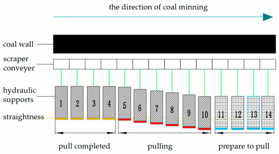
Figure 3.
Sequenced pulling of hydraulic supports.
The operation process of staggered pulling of hydraulic supports is shown in Figure 4. Hydraulic supports 5–10 can be divided into three groups. Firstly, hydraulic supports 5, 7, and 9 are simultaneously pulled. After their pulling is completed, hydraulic supports 6, 8, and 10 are then pulled to achieve synchronous operation and staggered pulling.
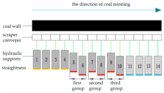
Figure 4.
Staggered pulling of hydraulic supports.
The operation process of group pulling of hydraulic supports is shown in Figure 5. Hydraulic supports 5–10 can be divided into two groups. Firstly, hydraulic supports 5 and 8 are simultaneously pulled. After the pulling is completed, hydraulic supports 6 and 9 are pulled. After this pulling is completed, hydraulic supports 7 and 10 are pulled to achieve the group pulling action.
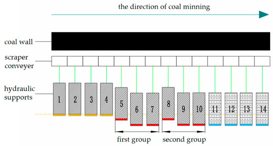
Figure 5.
Group pulling of hydraulic supports.
Although the sequential operation is easier and can be completed by only operating the oil cylinder once, the operation efficiency will be reduced. In the case of improving the efficiency of coal mining, the use of staggered pull supports and group pull supports can better ensure efficient mining, but the use of staggered or group methods needs to ensure the synchronization of each push cylinder, and it is necessary to improve the positioning accuracy of the multi−cylinder pull support control system.
- (1)
- Flow continuity equation of the hydraulic cylinder
When constructing the continuous equation of the hydraulic cylinder, it is assumed that the cylinder is an ideal cylinder—that is, ignoring the influence of pipeline friction and pipeline dynamic characteristics. It is assumed that the pressure in the asymmetric cylinder’s working chamber is equal everywhere, the volume modulus of the emulsion thermometer is constant, and the leakage coefficient of the cylinder is constant.
The pressure flow continuity equation of asymmetric cylinder is established as follows [23]:
where is the elastic modulus of the emulsion, is the leakage coefficient of the asymmetric cylinder, is the piston chamber volume of the asymmetric cylinder, is the rod cavity volume of the asymmetric cylinder, and and are the integration of the error of the parameter uncertainty of the two cavities of the asymmetric cylinder.
- (2)
- Load force balance equation
- (3)
- Mathematical model of the electrohydraulic directional valve
The electrohydraulic directional valve is a cartridge valve, which is controlled by two pilot valves and two main valves to realize the conversion of electro−mechanical−hydraulic input. The mechanical dynamics model of the valve can be analyzed to determine the characteristics of the valve.
The flow equation of the pilot valve of the electrohydraulic directional valve is
where is the flow area of the pilot valve, is the pilot valve’s seat hole diameter, is the spool diameter, is the valve’s port flow coefficient, is the valve’s port opening, is the emulsion density, is the pilot valve’s outlet pressure, and is the value related to the valve’s hole parameter.
The flow equation of the fixed damping hole at the front end of the main valve is
where is the diameter of the damping hole, is the dynamic viscosity of the emulsion, is the length of the damping hole, and and are the pressure before and after the damping hole, respectively.
Since the main spool is opened according to the pressure difference between the front and back of the spool, the viscous resistance of the spool, the friction resistance of the sealing ring, and the clamping resistance caused by eccentricity are ignored here. The steady−state fluid force of the spool and the continuity equation of the main valve flow are the main parameters analyzed.
The flow force model of the directional valve is shown in Figure 6. The steady flow force of the valve port is as follows [24]:
where is the flow density, is the flow rate, and are the speed of the valve port in and out of the fluid, respectively, and are the speed of the fluid at both ends of the flow channel, is the half-angle of the cone valve, and is the inlet angle of the valve sleeve.
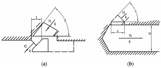
Figure 6.
Flow force model of the directional valve: (a) Flow force model at the valve port. (b) Flow force model at the flow channel.
The main valve port flow equation is
where is the flow area of the main valve and is the outlet pressure of the guide valve.
The above is the dynamic equation of each component of the valve−controlled cylinder system. The above model is sorted out, and the state variable of cylinder i is taken as follows:
where, is the displacement of the asymmetric cylinder, and is the the speed of the asymmetric cylinder.
The state−space equation of the system is
Finally, taking multiple passage cylinders in a fully mechanized mining face as the research object, assuming that the structure and parameters of each cylinder are the same, the model of multi−cylinder cooperative control can be expressed as the following state equation:
3. Design of Controller
3.1. State Observer
Due to the complexity of the actual situation of the mine, the parameter signals required for the control process are unknown and cannot be measured in the actual situation, and the hydraulic support pull load has strong time-varying load characteristics—that is, it is impossible to track all of the system states of the valve-controlled cylinder under complex working conditions. Therefore, a control strategy for a multi-cylinder synchronous control process is proposed. Based on iterative learning control, the state observer is used to estimate the parameters that cannot be measured by the system to improve the control accuracy of the valve-controlled cylinder system during the pulling process.
From the analysis of the previous section, the state−space equation composed of displacement, velocity, and acceleration can be expressed as follows:
The purpose of designing a state observer is to use the output information to observe the state of the system. Let the state observer equation be
Substituting the state−space equation into the state observer equation can obtain
The system is the estimated value of the state observer, and is the output of the estimated value. In the process of support pulling, the displacement signal is a known quantity, and the velocity signal and acceleration signal can be derived from the displacement signal. However, the signal obtained after the second digital differentiation is seriously affected by the environmental noise. In order to simplify the design of the observer, there is no need to design a full−order state observer—only the velocity and acceleration can be observed.
3.2. P−Type Iterative Learning Controller (P−ilc)
The iterative learning control method is suitable for a controlled object with repetitive motion characteristics, and it can achieve the position accuracy of the controlled object in a limited time. The control method corrects the control signal by the deviation between the actual output of the system and the given position through continuous learning of the controlled system, thereby generating a more accurate control signal and improving the position control performance of the system [25,26].
The principle of iterative learning control is as follows [27]: Suppose a dynamic system , is a continuous mapping with time, and is the control objective to output tracking of the desired output signal . The control process is equivalent to obtaining the optimal input in the controller, such that
The optimal input is obtained by iterative learning method, so that the sequence converges to the desired optimal signal ; that is, there is a sequence
Making
In the actual signal measurement system, there will be measurement noise, which will seriously affect the operation of the learning law. In order to improve the fast−tracking performance of the system, appropriate methods should be used to suppress the influence of noise. The most commonly used method is to calculate the low−order derivative as much as possible in the learning law, or to directly use the output error. The most commonly used learning law is the P−type learning law, as follows:
where is the output error, while is the learning gain coefficient or gain matrix. The above equation can be expressed as follows:
Through the P−type learning law, the output error signal can be accumulated to form a controllable input signal of the system. The schematic diagram of iterative learning control using the P−type learning law is shown in Figure 7.
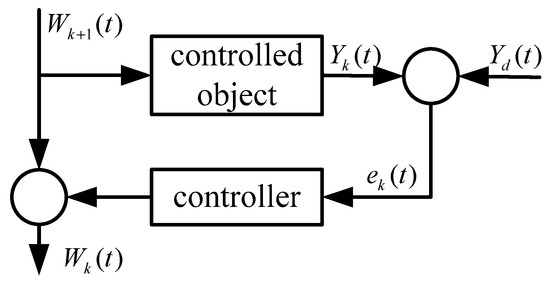
Figure 7.
Schematic diagram of P−type iterative learning control.
In the existing research, the convergence condition of the P−type learning law in linear systems is given, which can be determined from the mathematical modeling of the pulling process in the previous section. The pulling process is a nonlinear discrete dynamic system. The convergence analysis of the system under the P−type learning law is as follows:
From the modeling of the pulling process system in the previous section, the controlled system can be expressed as follows:
The output t within is required to track the desired output . At the Kth run, the dynamic process of iterative learning is
The output error is
where represents the values of the kth run, respectively. From the previous P−type learning principle, the P−type learning strategy is
The dynamic process expression of iterative learning and the P−type learning strategy can be substituted into the above formula to obtain
And because f and g are continuous functions,
From Equations (30) and (31), we can get
For the process of pulling the bracket, the initial state error of each operation is converged to zero; that is, , so , and there is a unique ideal control during the operation of the bracket, so that the state and output of the system are . The spectral radius can be proven by the above formula and mathematical induction (detailed proof not provided here), so the learning law converges when applied to the pulling system.
Under different expected trajectories, 30 iterations were carried out in the iterative controller. The iterative results and the root−mean−square error are shown in Figure 8 and Figure 9, respectively. After 30 iterations, the results were essentially consistent with the expected trajectory, and the root−mean−square error was close to zero, indicating that the P−type iterative learning controller achieved the expected effect with the increase in the number of iterations.
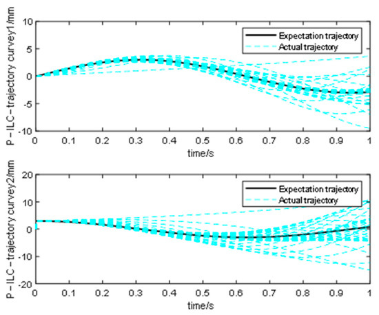
Figure 8.
Results after 30 iterations of different expected trajectories.
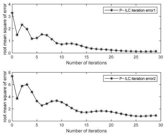
Figure 9.
Root−mean−square error after 30 iterations of different trajectories.
4. Simulation Analysis of Single−Cylinder and Multi−Cylinder Pulling Systems
4.1. Control Strategy and Modeling of a Hydraulic Support Multi−Cylinder Pulling System
The mathematical model of the multi−cylinder control system is constructed above. The following is the construction of the valve-controlled cylinder simulation model of the multi−cylinder pull support system. This section establishes the simulation model based on the multi-cylinder cooperative position control principle shown in Figure 10.
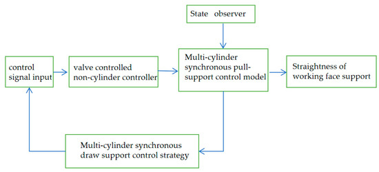
Figure 10.
Position control principle of a multi−cylinder rack−shifting system.
In the simulation, a ZY 8000/25/50 (S) D−type shield hydraulic support was used to set the specific parameters, such as the size, structure, and material of each actuator. Some of the parameters are shown in Table 1.

Table 1.
Main parameters of the simulation model.
The co-simulation system is shown in Figure 11. Figure 12 shows the joint simulation block model. Panels (a), (b), and (c) in Figure 11 correspond to panels (a), (b) and (c) in Figure 12, respectively. In this system, the physical simulation model of three push cylinders is established by SimulationX, and the control model is established by Simulink. Among them, the pressure and position signals required in Simulink come from the physical model established in SimulationX, while the control electrical signals required by the physical model in SimulationX are calculated by the control module in Simulink, in which the electrohydraulic directional valve is encapsulated by the SimulationX encapsulation function, and the control is controlled.
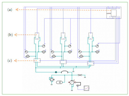
Figure 11.
Joint simulation model of a multi−cylinder broach position control system: (a) Controller simulation model. (b) Hydraulic support packaging model. (c) Simulation model of electrohydraulic directional valve.
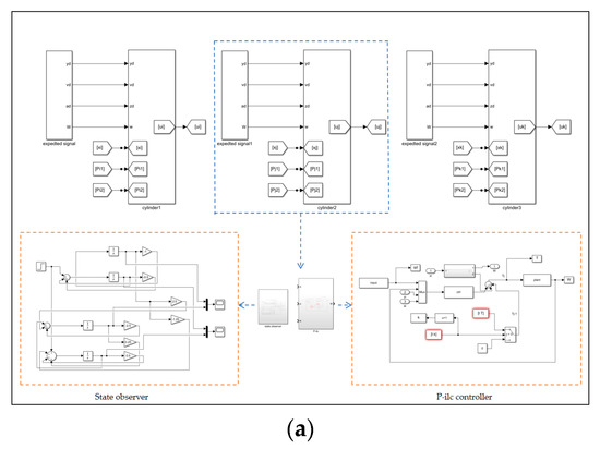
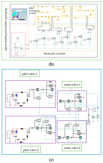
Figure 12.
Joint simulation block model: (a) Controller simulation model. (b) Hydraulic support packaging model. (c) Simulation model of electrohydraulic directional valve.
The signals received in the module include the No. 1, No. 2, and No. 3 brackets pushing the cylinder without cylinder chamber pressure, cylinder displacement, and rod cylinder chamber flow, and controlling the switching signal of the electrohydraulic directional valve (the displacement, velocity, and acceleration of the cylinder can be measured by the displacement sensor).
4.2. Simulation Results and Analysis
In order to better illustrate the effectiveness of the iterative learning control strategy, another backpropagation (BP) neural network learning strategy [28] (as shown in Figure 13) was designed for comparative analysis. A BP neural network is a multilayer feedforward neural network trained according to the error backpropagation algorithm. It does not need to set the mathematical equations of input and output in advance, and it can constantly adjust the network’s weight and threshold value by using the steepest descent method to achieve the goal of minimizing the sum of squares of errors between the actual output and the expected output. For BP neural networks, the signals at each layer have the following relationship:
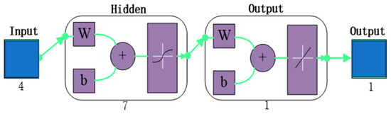
Figure 13.
BP neural network.
- (1)
- Input of hidden layer (ith node):
- (2)
- Output of hidden layer (ith node):
- (3)
- Input of the jth node in the output layer:
- (4)
- Output of the kth node in the output layer:
In the above equations, represents the network input, represents the weights of the ith unit in the input layer and the jth unit in the hidden layer, and is the weight of the jth unit in the hidden layer and the kth unit in the output layer.
and are the thresholds of the ith unit of the hidden layer and the output layer, respectively, while and are the activation function of the hidden layer and the input layer, respectively, and the activation function takes the sigmoid function.
The test used 40 sets of data; the inputs were the cylinder pressure, flow, displacement, and speed, and the corresponding output was the advance. The training set was 70%, the verification set was 15%, the test set was 15%, and the number of hidden-layer neurons was 7. The setting method was as follows:
Firstly, if the number of input layer nodes in the BP neural network is m and the number of output layer nodes is n, then the number of hidden−layer nodes can be derived as S using the following formula, where b is generally an integer of 1–9:
Therefore, for the hidden−layer neurons in this study, .
Secondly, the cross−validation method was used to divide the dataset into a training set, a validation set, and a testing set. The neural network was trained with different hidden layers and tested on the validation set to select the best−performing hidden layer. The optimization of the number of hidden−layer nodes in BP neural networks can be achieved using a simple MATLAB program.
The following is a comparative simulation of the single−cylinder pulling process: The system flow is 150 L/min and the load pressure is 100 kN. The iterative learning is also based on the above data for offline learning.
Figure 14 show the trajectory−tracking diagrams of different controllers for the sinusoidal signal of a single−cylinder rack. Before 6s, the control system is not involved, and the state of the discrete acquisition system is started from 6s to analyze the amount of advance required to reach 600 mm.
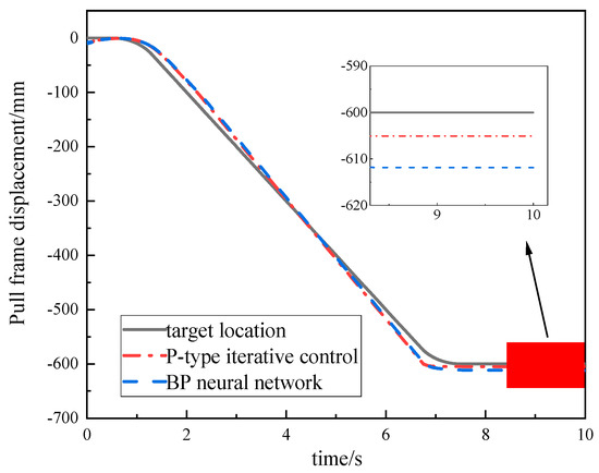
Figure 14.
Trajectory−tracking effects with different controllers.
The P−type iterative learning control is switched at 6.23 s, and the final displacement error is 4.2 mm. The controller based on BP neural network learning switches at 6.5 s, and the final displacement error is 12.4 mm. This shows that the P−type iterative learning control has higher position accuracy for the valve-controlled cylinder system during the pulling process under the same conditions.
There are two types of multi−cylinder pull support: staggered pull support and group pull support. These two methods of pull support can be attributed to the position synchronization problem of multi−cylinder pull support. In the simulation analysis of multi−cylinder pull support, multi−cylinder synchronization was used to prove the effectiveness of the controller. The simulation results are shown in Figure 15.
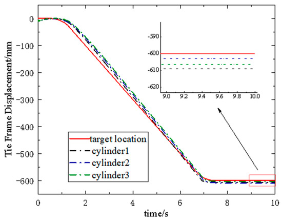
Figure 15.
Multi−cylinder pulling trajectory−tracking effect.
From the figure, it can be seen that in the state of the three−cylinder simultaneous pulling system, the advance of cylinder 1 switches at 7.18 s, and the final displacement error is 9.2 mm; the advance of cylinder 2 is switched at 7.11 s, and the final displacement error is 3.4 mm; the advance of cylinder 3 is switched at 7.16 s, and the final displacement error is 7.4 mm. The final position synchronization error of the three cylinders is 5.8 mm. The simulation results show that the error of P-type iterative learning control is small when it is applied to multi−cylinder synchronous broaching, which proves the effectiveness of the control strategy under study.
5. Test Analysis
The test bench was mainly composed of a driving system and a loading system. The driving system included a pumping station, a proportional relief valve, an electrohydraulic directional valve, and a driving cylinder. The displacement of the control cylinder and the pressure signal of the two chambers of the cylinder were measured by the displacement sensor and the pressure sensor, respectively, and fed back to the controller. The loading system mainly included a loading pump, electromagnetic directional valve, proportional relief valve, and loading cylinder. The retraction of the driving cylinder simulated the pulling process of the downhole hydraulic support, and the loading cylinder mainly simulated the load force in the pulling process. Figure 16 shows a physical diagram of the multi−cylinder collaborative pull support test platform, which was provided by an emulsion supply tank with a capacity of 1500 L. The liquid supply system mainly used a mine milk with a rated flow rate of 200 L/min. As the main liquid supply pump, the motor was controlled by a QJZ6-80/1140 (660, 380) N mine flameproof and intrinsically safe reversible vacuum electromagnetic starter. Table 2 shows the equipment parameters used in the test rig.
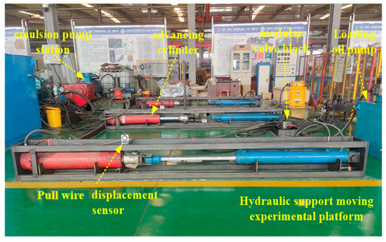
Figure 16.
Three−cylinder collaborative puller test rig.
Table 2.
The equipment parameters used in the test rig.
In the above table, 1% FS represents the percentage of full scale (i.e., maximum flow scale value). The data acquisition card used in this study was an Altai PCI 5654 with a maximum sampling rate of 500 K and a sampling accuracy of 16 bits.
5.1. Single−Cylinder and Multi−Cylinder Pulling Control Method Tests
According to the actual investigation on the site, most of the position control methods of the pulling support in the fully mechanized mining face now adopt the manual positioning of the pulling line, so the first method in the test adopted the visual positioning of the pulling line to pull the support. The second was to use PLC position feedback for positioning—that is, internal closed-loop control. First, the PLC controlled the opening and closing of the electrohydraulic directional valve, and then the electrohydraulic directional valve controlled the displacement of the cylinder. The cylinder was equipped with a displacement sensor. The displacement sensor fed the displacement signal back to the PLC to achieve internal closed-loop control. The third method used the P-type iterative learning controller studied in this paper—that is, the P−ilc control method for positioning.
Each positioning method was divided into two groups of experiments: the first group was positioned at 600 mm with a flow rate of 100 L/min, and the second group was positioned at 600 mm with a flow rate of 135 L/min. The two groups of experiments were carried out in turn. In order to show the experimental results, the data were mainly intercepted from the process of pushing the cylinder, so the time coordinate axis of each positioning method was continuously distributed. The experimental results are shown in Figure 17 and Figure 18.
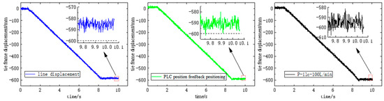
Figure 17.
Displacement curves of three different positioning methods at 100 L/min.
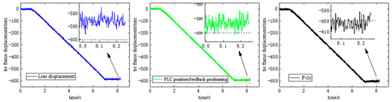
Figure 18.
Displacement curves of three different positioning methods at 135 L/min.
Table 3 shows the final displacement error of the cylinder. From the table, it can be seen that the final cylinder error increased with the increase in the flow rate when the cable−type visual manual positioning was performed, and it is uncertain whether the cylinder is deficient or excessive. When relying on feedback positioning, the error is smaller than manual positioning, and the error is generally excessive. Compared with the above two methods, the error is significantly reduced when using P−ilc control, which meets the requirements of the straightness of the support, verifying the effectiveness of this control method.
Table 3.
Positioning error of different control methods for a single cylinder.
5.2. Verification of the Multi-Cylinder Synchronous Draw Support Control Method
Due to the limitations of the testing site, the multi−cylinder synchronous pull frame experiment was conducted using three hydraulic cylinders, with a target position of 600 mm. Figure 19 and Figure 20 show the positioning control experimental results of three sets of hydraulic cylinders at 100 L/min and 135 L/min flow rates, respectively. From Figure 19, it can be seen that when the flow rate is 100 L/min, the final displacements of cylinders 1, 2, and 3 are 593 mm, 596 mm, and 602 mm, respectively; the positioning errors are −7 mm, −4 mm, and 2 mm, respectively, with a maximum displacement difference of 9 mm among the three cylinders. When the flow rate is 135 L/min, the final displacements of cylinders 1, 2, and 3 are 610 mm, 595 mm, and 602 mm, respectively; the positioning errors are 10 mm, −5 mm, and 2 mm, respectively, with a maximum displacement difference of 15 mm among the three cylinders. The above results meet the positioning control accuracy requirements of the hydraulic support pushing system.
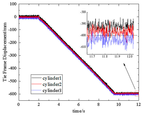
Figure 19.
P−ilc positioning at 100 L/min.
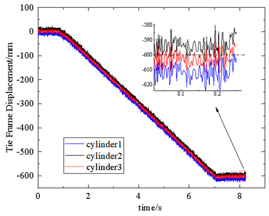
Figure 20.
P−ilc positioning at 135 L/min.
6. Conclusions
- (1)
- Due to the actual working conditions of high pressure, large flow, and high−water base underground, the electrohydraulic directional valve is still used as the control component. Studying the positioning control strategy of the hydraulic support pushing system for the electrohydraulic directional valve is the key to solving the low straightness of the overall hydraulic support group in the underground, fully mechanized mining face. For this reason, a predictive positioning control method is proposed, in which the state observer overestimates the unmeasurable parameters of the system and the iterative learning controller is used to predict the advance of the cylinder’s position. This method is one of the new ways to solve the above problems.
- (2)
- The process of pulling the hydraulic support with the electrohydraulic reversing valve as the control element was modeled mathematically, the single−cylinder and multi−cylinder synchronous controllers were designed, and the joint simulation model was established. The results showed that after 30 iterations, the trajectory is essentially consistent with the expected trajectory, and the mean square error approaches zero. Compared with BP neural networks and other controllers, the simulation and experimental results show that, using P−type iterative learning, the single−cylinder positioning control accuracy can be controlled within 10 mm, and the synchronization error of the three cylinders is within 15 mm.
- (3)
- The P−type iterative method solves the problem of large positioning error caused by undesirable characteristics such as low switching frequency and time delays in the control process of the electrohydraulic directional valve. In the process of controlling the straightness of the entire working face in the coal mine site, there will still be random errors and cumulative errors. Developing a control method that integrates internal and external closed−loop control, and applying digital twin and signal processing related technologies to it, will be the next focus of our work.
Author Contributions
Conceptualization, Z.K. and J.W.; data curation, T.H. and T.J.; formal analysis, T.H.; funding acquisition, Z.K. and J.W.; investigation, K.S. and B.D.; methodology, K.S.; project administration, Z.K. and J.W.; resources, Z.K. and J.W.; software, T.H.; supervision, Z.K. and J.W.; visualization, T.J.; writing—original draft, T.H. and T.J.; writing—review and editing, T.H. All authors have read and agreed to the published version of the manuscript.
Funding
This research was funded by the National Natural Science Foundation of China “Study on high pressure, large flow and high water-based digital valve and its control method in mining” (Project No. U1910212).
Institutional Review Board Statement
Not applicable.
Informed Consent Statement
Not applicable.
Data Availability Statement
Not applicable.
Conflicts of Interest
The authors declare no conflict of interest.
References
- Zhang, Y.; Zhang, H.; Gao, K.; Xu, W.; Zeng, Q. New Method and Experiment for Detecting Relative Position and Posture of the Hydraulic Support. IEEE Access 2019, 42, 181842–181854. [Google Scholar] [CrossRef]
- Ren, H.; Zhang, S.; Zhang, D.; Zhou, J.; Ren, C.; Miao, X.; Liu, K.; Hou, W. Research status and development trend of hydraulic support precision nudging and fast following technology. Ind. Min. Autom. 2022, 48, 1–9+15. [Google Scholar]
- Li, W.; Zhou, Z. Automatic straightening technology of header mining face based on inertial guidance system. Shaanxi Coal 2022, 41, 130–133+146. [Google Scholar]
- Wang, G. Development direction of automation, intelligent and unmanned set of technology and equipment for header mining. Coal Sci. Technol. 2014, 42, 30–39. [Google Scholar]
- Jin, L.-Y.; Wang, Q.-F. Positioning control of hydraulic cylinder with unknown friction using on/off. Proc. Inst. Mech. Eng. Part I J. Syst. Control. Eng. 2018, 232, 983–993. [Google Scholar]
- Yang, H.; Guo, Y.; Zhang, H.; Wang, X.; Lin, B.; Dang, Y. Research on the position control system of hydraulic cylinder based on solenoid-operated reversing valve. Mech. Des. Manuf. Eng. 2020, 49, 101–104. [Google Scholar]
- Wang, Y.; Zhao, J.; Wang, H.; Ding, H. Output feedback control for the driving cylinder of hydraulic support with error constraint. J. Vib. Control. 2023, 29, 3126–3136. [Google Scholar] [CrossRef]
- Wang, Y.; Zhao, J.; Cao, C. Position control of asymmetric cylinder electrohydraulic system based on double disturbance observer. J. Cent. South Univ. 2021, 52, 3864–3871. [Google Scholar]
- Wang, X. A hybrid model predictive controller design for hydraulic servo system position tracking. Mach. Tools Hydraul. 2020, 48, 132–136. [Google Scholar]
- Chou, Z.; Su, Q.; Fang, Z.; Li, H.; Chen, D.; Fang, L. A state feedback-based control method for proportional servo valves. Flight Control. Detect. 2022, 5, 39–47. [Google Scholar]
- He, C.; Shi, G.; Guo, Q.; Wang, D. Adaptive robust control strategy for valve-controlled asymmetric hydraulic cylinder position control system. J. Shanghai Jiaotong Univ. 2019, 53, 209–216. [Google Scholar]
- Yu, B.; Jin, Z.; Wang, X.; Lou, W.; Song, Y.; Li, H.; Qin, H. Dynamic performance analysis and experimental study of incremental digital valve-controlled cylinder position control system. Eng. Sci. Technol. 2020, 52, 183–189. [Google Scholar]
- Guo, Y.-Q.; Zha, X.-M.; Shen, Y.-Y.; Wang, Y.-N.; Chen, G. Research on PID Position Control of a Hydraulic Servo System Based on Kalman Genetic Optimization. Actuators 2022, 11, 162. [Google Scholar] [CrossRef]
- Zhang, Y.; Li, K.; Cai, M.; Wei, F.; Gong, S.; Li, S.; Lv, B. Establishment and Experimental Verification of a Nonlinear Position Servo System Model for a Magnetically Coupled Rodless Cylinder. Actuators 2022, 11, 50. [Google Scholar] [CrossRef]
- Wang, Z.; Jing, X.; Chao, T.; Lei, S. Moving distance measurement for hydraulic support based on fruit flyoptimization algorithm. Opt. Eng. 2017, 56, 856–865. [Google Scholar]
- Wang, B.; Xie, J.; Wang, X.; Liu, S.; Liu, Y. A New Method for Measuring the Attitude and Straightness of Hydraulic Support Groups Based on Point Clouds. Arab. J. Sci. Eng. 2021, 46, 11739–11757. [Google Scholar] [CrossRef]
- Kelly, M.; Hainsworth, D.; Reid, D.; Lever, P.; Gurgenci, H. Longwall automation: A new approach. In Proceedings of the 3th International Symposium High Performance Mine Production, Melbourne, FL, USA, 19–22 November 2003; CRISO Exploration&Mining: Aachen, Germany, 2003; pp. 5–16. [Google Scholar]
- Reid, D.C.; Hainsworth, D.W.; Ralston, J.C.; McPhee, R.J.; Hargrave, C.O. Inertial Navigation: Enabling Technology for Longwall Mining Automation; Computer Application in Minerals Industries: Calgary, AB, Canada, 2003. [Google Scholar]
- ANON. Directorate—General for Research and Innovation. New Mechanisation and Automation of Longwall and Drivage Equipment; European Commission: Luxembourg, 2011; pp. 1–14. [Google Scholar]
- JOY Global Inc. Joy advanced shearer automation. Coal Int. 2013, 261, 61–64. [Google Scholar]
- CATPILLAR Inc. Setting the record straight longwall production. Coal Int. 2013, 261, 34–37. [Google Scholar]
- Ge, S.; Zhang, F.; Wang, S.; Wang, Z. Research on the Technical Architecture of Digital Twin Intelligent Mining Faces. J. Coal Ind. 2020, 45, 1925–1936. [Google Scholar]
- Wang, Y. Research on the Control Strategy of Multi-Cylinder Cooperative System of Hydraulic Support Group. Ph.D. Thesis, China University of Mining and Technology, Beijing, China, 2021. [Google Scholar]
- Liao, Y.; Ren, H.; Zhang, D.; Lian, Z. Hydrodynamic calculation method of hydraulic support reversing valve and its application. J. Coal 2019, 44, 1609–1615. [Google Scholar]
- Cao, J.; Wei, M.; Zhao, H. Adaptive iterative learning control of a hybrid-drive flex-cable parallel robot. Mech. Drives 2022, 46, 42–47. [Google Scholar]
- Lin, J.; Fang, Y.; Lu, B.; Hao, Y.; Cao, H. Iterative learning and neural network based control of marine cranes. Control. Theory Appl. 2022, 39, 602–612. [Google Scholar]
- Meng, Q.; Nan, X.; Zhang, Y. Trajectory tracking control of robotic arm based on PD-type iterative learning. Comb. Mach. Tools Autom. Mach. Technol. 2022, 585, 62–65+69. [Google Scholar]
- Liang, J.; Li, C. Cooperative control of hydraulic support multi-cylinder based on neural network approximator. Coal Technol. 2023, 42, 223–225. [Google Scholar]
Disclaimer/Publisher’s Note: The statements, opinions and data contained in all publications are solely those of the individual author(s) and contributor(s) and not of MDPI and/or the editor(s). MDPI and/or the editor(s) disclaim responsibility for any injury to people or property resulting from any ideas, methods, instructions or products referred to in the content. |
© 2023 by the authors. Licensee MDPI, Basel, Switzerland. This article is an open access article distributed under the terms and conditions of the Creative Commons Attribution (CC BY) license (https://creativecommons.org/licenses/by/4.0/).