1. Introduction
With the elderly population increasing gradually, insufficient available labor has arisen everywhere. Especially in agriculture, a serious lack of manpower may threaten crop production in the world. Therefore, research in smart agriculture offers an advantage to reduce the labor required. Among the attempts made, crop or fruit harvesting using an agricultural robot is an important priority [
1,
2,
3].
An available agricultural robot can successfully pick crops and fruits that are grown in a complex, unknown, and unstructured environment. Hence, the agricultural robot must have the ability to detect targets. In this regard, vision is required for the agricultural robot to identify the positions and postures of targets. Moreover, fruits and crops have different shapes, colors, sizes, and types; therefore, harvesting algorithms must be developed for robots to perform successful picking. Currently, the key technique for overall performance of a harvesting robot lies in the performance of vision-based feedback control [
4].
Vision-based control aims to detect and recognize the target crops and fruits via camera; their position and pose in space are acquired so that the coordinates and orientations are then used to control the motion of the robotic manipulator. In the detection and recognition of target fruit, many approaches rely on deep learning algorithms. Ji et al. [
5] proposed the Shufflenetv2-YOLOX-based apple object detection to enable the picking robot to detect and locate apples in the orchard’s natural environment. This method provides an effective solution for the vision system of the apple picking robot. Xu et al. [
6] used an improved YOLOv5 for apple grading. The experiments indicated that this method has a high grading speed and accuracy for apples. Sa et al. [
7] presented deep convolutional neural networks for fruit detection. The proposed detector can handle approximately 50% of scaled-down object detection. However, control by visual servo is also essential for the successful operation of the robotic harvesting system. Based upon error signals, the visual servo controls are generally classified as PBVS and IBVS [
8,
9].
In the PBVS algorithm, a 3D model of target objects and camera parameters are required. The relevant 3D parameters are computed through the pose of the camera within a reference frame. The absolute or relative positions of the harvesting robot with respect to target objects can thus be determined using the visual 3D parameter information [
10]. The controllers are then designed based on the position errors so that the robotic manipulator can move to an operation position to execute a picking action. For the application of PBVS to agricultural harvesting, Jun et al. [
11] proposed a harvesting robot that combines robotic arm manipulation, object 3D perception, and an end cutting mechanism. For software integration, the Robot Operating System (ROS) was used as a framework to integrate the robotic arm, gripper, and related sense tester. Edan et al. [
12] described the intelligent sensing, planning, and control of a robotic melon harvester. Image processing for PBVS is used to detect and locate the melons. Planning algorithms with the integration of task, motion, and trajectory were presented. Zhao et al. [
13] developed an apple-harvesting robot that is composed of a manipulator, an end effector, and an image-based vision servo control system. The apple was detected using a support vector machine-based fruit recognition algorithm. The apple harvesting success rate was evaluated through PBVS. Lehnert et al. [
14] presented a robotic harvester that can autonomously pick sweet pepper. A PBVS algorithm acquires 3D localization to determine the cutting pose and then to grasp the target with an end effector. Field trials demonstrated the efficacy of this approach. However, for PBVS, exact knowledge of the intrinsic parameters of the camera is required for control performance. Even very small errors in the camera calibration may greatly affect the control accuracy of robots [
15].
IBVS directly uses image features that are converted from pixel-expressed images by the camera system to design the controllers. Visual features are first extracted from the image space. The errors are computed from points or vectors by the visual features [
16]. Mehta et al. [
17] developed a vision-based harvesting system for robotic citrus fruit picking. The cooperative visual servo controller was presented to servo the end effector to the target fruit location using a pursuit-guidance-based hybrid translation controller. The visual servo control experiment was performed and analyzed. Li et al. [
18] investigated an image-based uncalibrated visual servoing control for harvesting robots and tried to resolve the overlapping effects of the target motion and the uncalibrated parameter estimation. The effectiveness of the proposed control was demonstrated by the comparative experiments. Barth et al. [
19] reported the agricultural robotics in dense vegetation with software framework design for eye-in-hand sensing and motion control. An image-based visual servo control was designed to correct the motion of the robot so that the geometrical feature error was minimized. Qualitative tests were performed in the laboratory using an artificial dense vegetation sweet pepper crop. Li et al. [
20] proposed an IBVS controller that mixes proportional differential control and sliding mode control. However, the visual servo controller is not completely designed to be perfect 100%, and there are unexpected interference phenomena in different environments or different hardware devices. Although the IBVS schemes are robust against the calibration errors in the camera, large calibration errors may cause the closed-loop system to be unstable [
21,
22,
23]. As a result, an advanced control design is required for stability. Moreover, an IBVS using a fixed camera on a robotic manipulator is limited to a field of view. That is, the target may always move out of the field of view as the manipulator turns, so that the IBVS controller will fail to control the manipulator.
In this paper extending from our previous study [
24], a robotic manipulator for cherry tomato harvesting was investigated in greater detail. The main contributions are highlighted as follows. A novel cutting and clipping integrated mechanism was designed for cherry tomato harvesting. The position of the cherry tomato in space was determined by the proposed feature geometry algorithm. To accurately and efficiently pick the target cherry tomato, an HVSC that improves PBVS and IBVS without camera calibration or a target model was proposed for visual feedback control. HVSC combines the Cartesian and image measurements for error functions. The rotation and the scaled translation of the camera between the current and desired views of an object were thus estimated as the displacement of the camera, and thus the harvesting system may perform with better stability.
2. Robotic Manipulator System for Harvesting
Harvesting robotic manipulators aim to perform effective picking on fruits and vegetables. Designs for harvesting robotic manipulators must take into account the machine perception of crops, and thus a machine vision system is required to recognize the status and postures of the target crops. Based on the identified crops, the robotic manipulator moves to a position where it is appropriate to harvest the detected crops in an uncertain, unstructured, and varying environment. The manipulation is always performed by visual servo control to make an end effector reach to the planned location and orientation. End effectors for harvesting are developed according to different harvesting methods, crops, and separated points from the stems. As a consequence, the proposed robotic manipulator in the paper for cherry tomato harvesting will be developed and designed according to these concepts.
2.1. Architecture Design and Software Setup
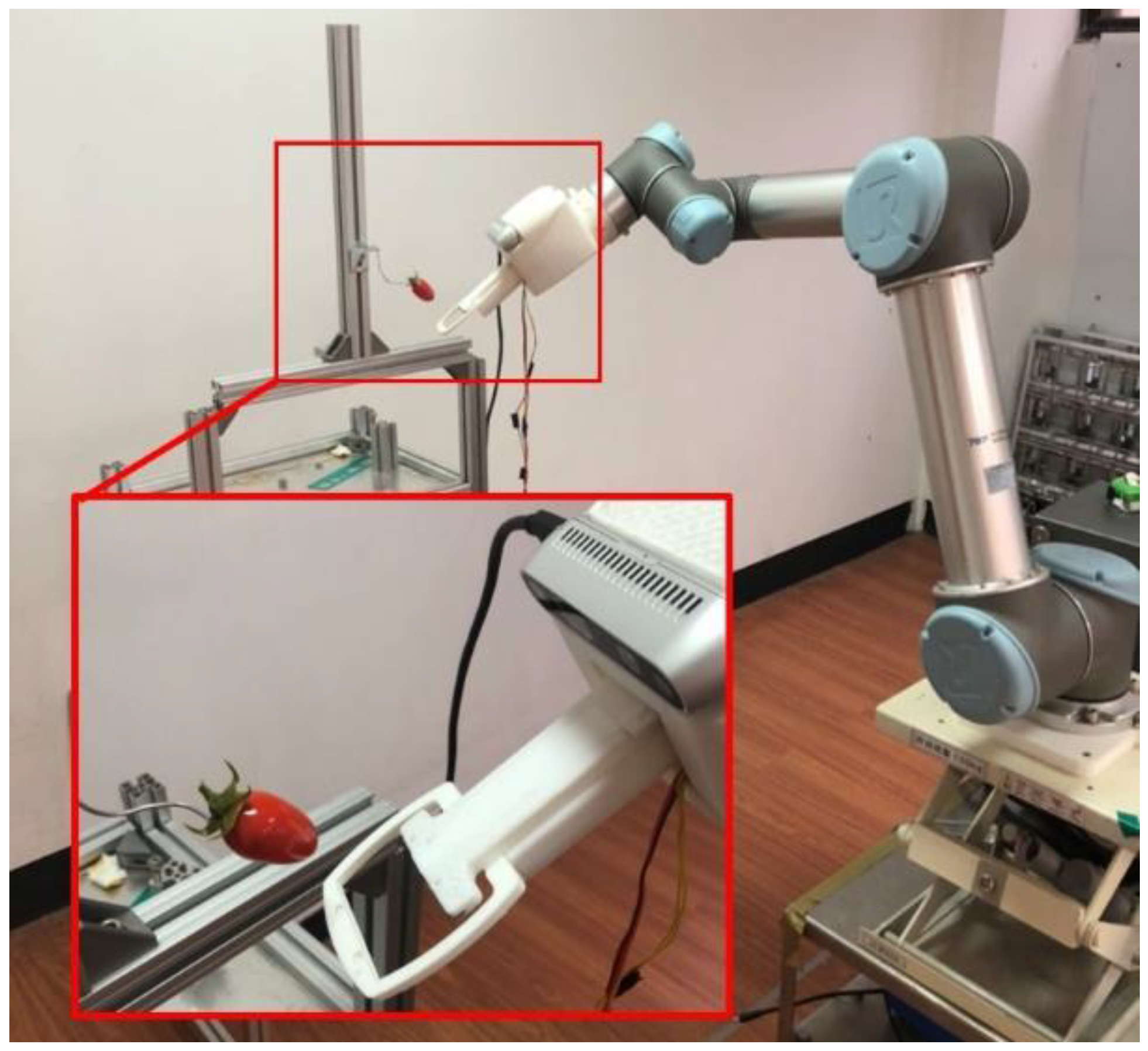
The architecture setup of the robotic manipulator for cherry tomato harvesting is presented in
Figure 1, in which the hardware is composed of a 6-DOF UR5 manipulator, a harvesting mechanism, and an RGB-D camera (Intel Realsense D435i). The RGB-D camera is mounted to the end effector of the manipulator in an eye-in-hand setup to transmit the data of the detected tomato to the embedded board. The images taken by the camera are used for visual recognition and visual servo feedback control such that the harvesting mechanism can be driven precisely and robustly by the manipulator to perform picking.
The software system of the harvesting robot manipulator is defined in the Robot Operating System (ROS) environment. Each subsystem can be represented as a node. The ROS supports Python and C++ programming languages, and the software is running on Ubuntu 18.04. Image data and depth data are processed by Python. The visual servo control is developed using C++ for tomato harvesting. Various open software libraries are linked for function implementation. The robotic manipulator moves by enabling the motion controller via software ROS packages.
2.2. Harvesting Mechanism
Many harvesting mechanisms have been designed to pick cherry tomatoes. Traditionally, a scissor type of cutting method must rely on the detection of the fruit stem by vision. However, it is not easy to identify the fruit stems because fruit stems are often occluded by leaves and fruits or easily misidentified as twigs. As a result, it is preferred to detect the target fruits directly but try to cut them from the fruit stems.
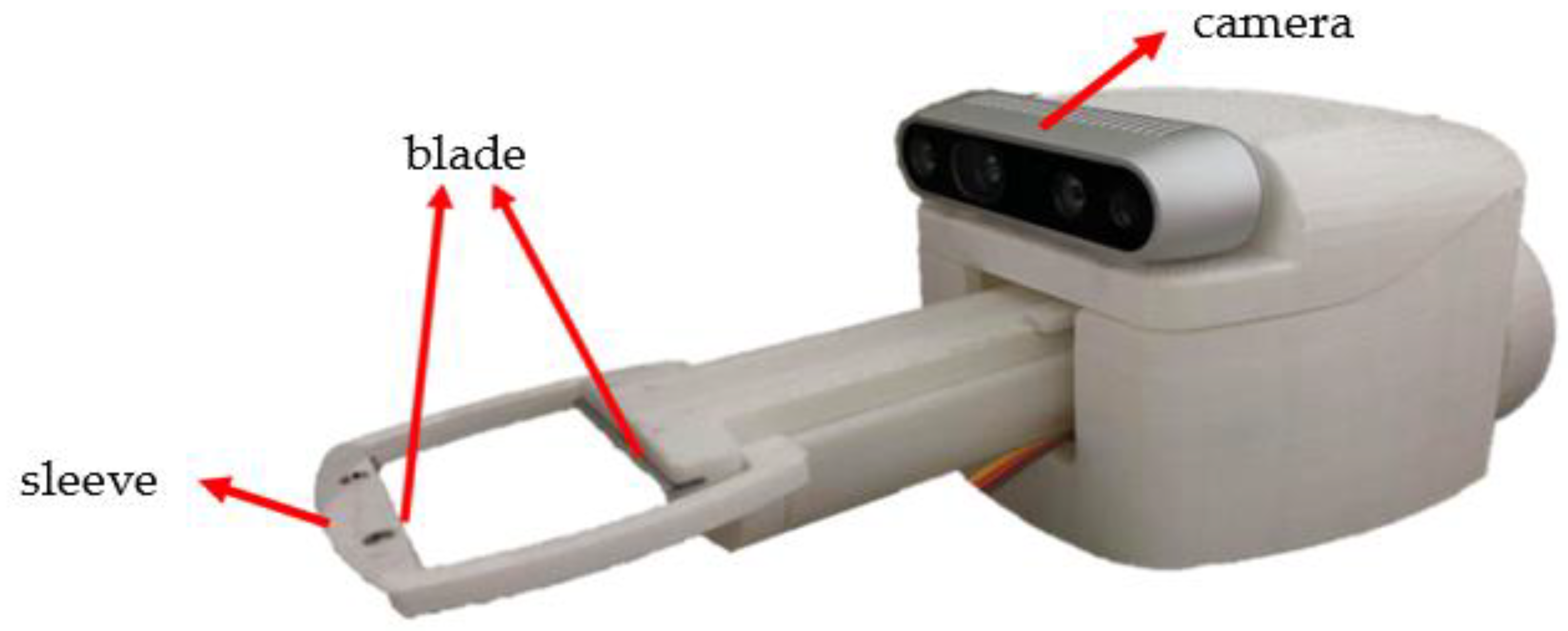
In this paper, a novel cutting and clipping integrated mechanism was proposed to pick cherry tomatoes, as presented in
Figure 2. Two blades are, respectively, mounted at the front and back of the rectangle sleeve. The rectangle sleeve can stretch out to pick cherry tomatoes and then return to its initial position. When the rectangle sleeve captures the target cherry tomato, the back blade moves forward to cut the fruit stem and clip the fruit.
2.3. Determination of Feature Points
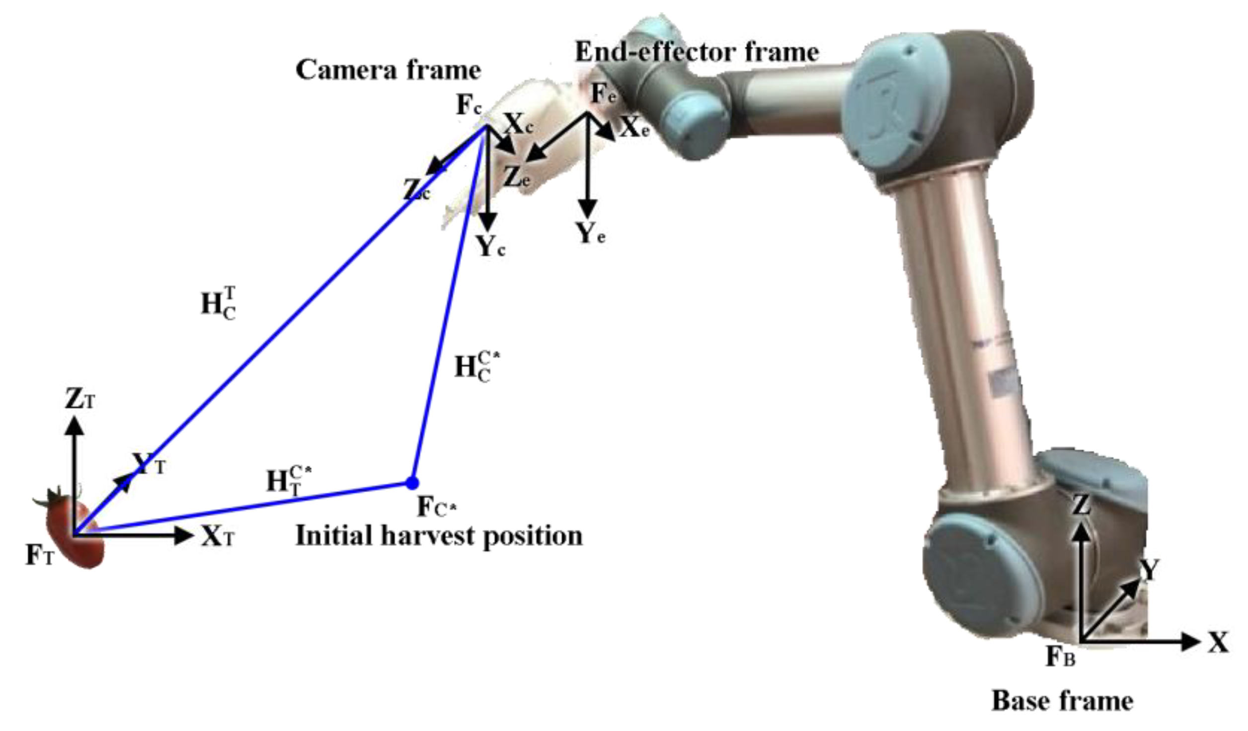
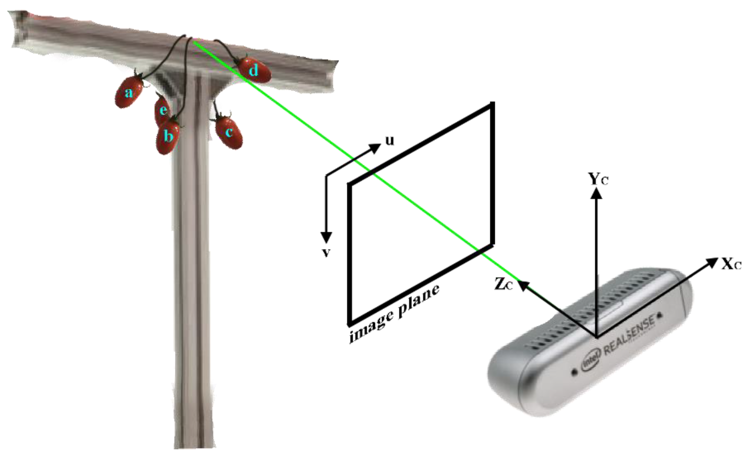
As the basis of our architecture setup of the robotic manipulator system for cherry tomato harvesting, the orthogonal frames, as shown in
Figure 3,
,
,
,
, and
are defined and, respectively, attached to the base of the robotic manipulator, the end effector, the camera, the initial operable position, and the cherry tomato center. For simplicity, the eye-in-hand camera is installed so that the camera frame {c} and end effector frame {e} are purely translational, and there is a rotational matrix
= I. Because the interrelationships between these assigned coordinate frames affect the success rate of reaching target fruits, the coordinate transformation relationship is essential. And the coordinate transformation is characterized by a rigid transformation including rotations and translations. The homogeneous transformation matrices
,
, and
, respectively, represent the transformations from the camera coordinate frame to the tomato coordinate frame and from the camera coordinate frame to the initial operable position. Accordingly, the operation position needed to cut the fruit stem can be estimated using the relationships of the homogeneous transformation matrices, which enables the robotic manipulator to reach the harvesting position to pick cherry tomatoes.
To pick fruits effectively, target detection and the determination of positions and orientations are required functions for the proposed harvesting robotic manipulator. The recognition and localization process rely on reliable recognition algorithms in a visual system. Most recognition algorithms adopt multiple-feature fusion approaches to extract the desired information of the target fruits. Among them, color, geometry, and texture are popular extracting features for target fruits [
25]. Color can be used to facilitate the segregation of target fruit from a complex environmental background. In general, the RGB images first captured by the camera are transformed to the YCrCb color space. Since a mature cherry tomato always appears red in color, only the Cr images that indicate the concentration offset of a red color are taken into account for mature cherry tomatoes. The color threshold values in OpenCV were applied to the filtered images [
26], in which a color value range is specified. The pixels in the image that satisfy the specified range will be registered; otherwise, the pixels out of the range are labeled as different colors or values. This method allows for the extraction or segmentation of specific color regions in the image, and thus the locations of tomatoes can be distinguished and determined.
The shape of the cherry tomato in space may be regarded as an ellipsoid, and the corresponding image is a 2D ellipse as projected onto the image plane. Due to its efficiency, this shape in the image plane is first recognized using the contour method [
27]. For the contour determination, a boundary point in the image must be determined as the starting point. This point will serve as the starting point to search the contour. All adjacent boundary points are traversed from this initial point along a closed boundary path. For each boundary point, the connectivity to its neighboring points must be examined to determine whether it is a branch point or a cross point. If there exist branch points or cross points, the topological structure features need to be updated. These features may contain a number of holes or connected regions. Finally, the shape in the image is thus determined after finishing the contour-following process until returning to the initial point.
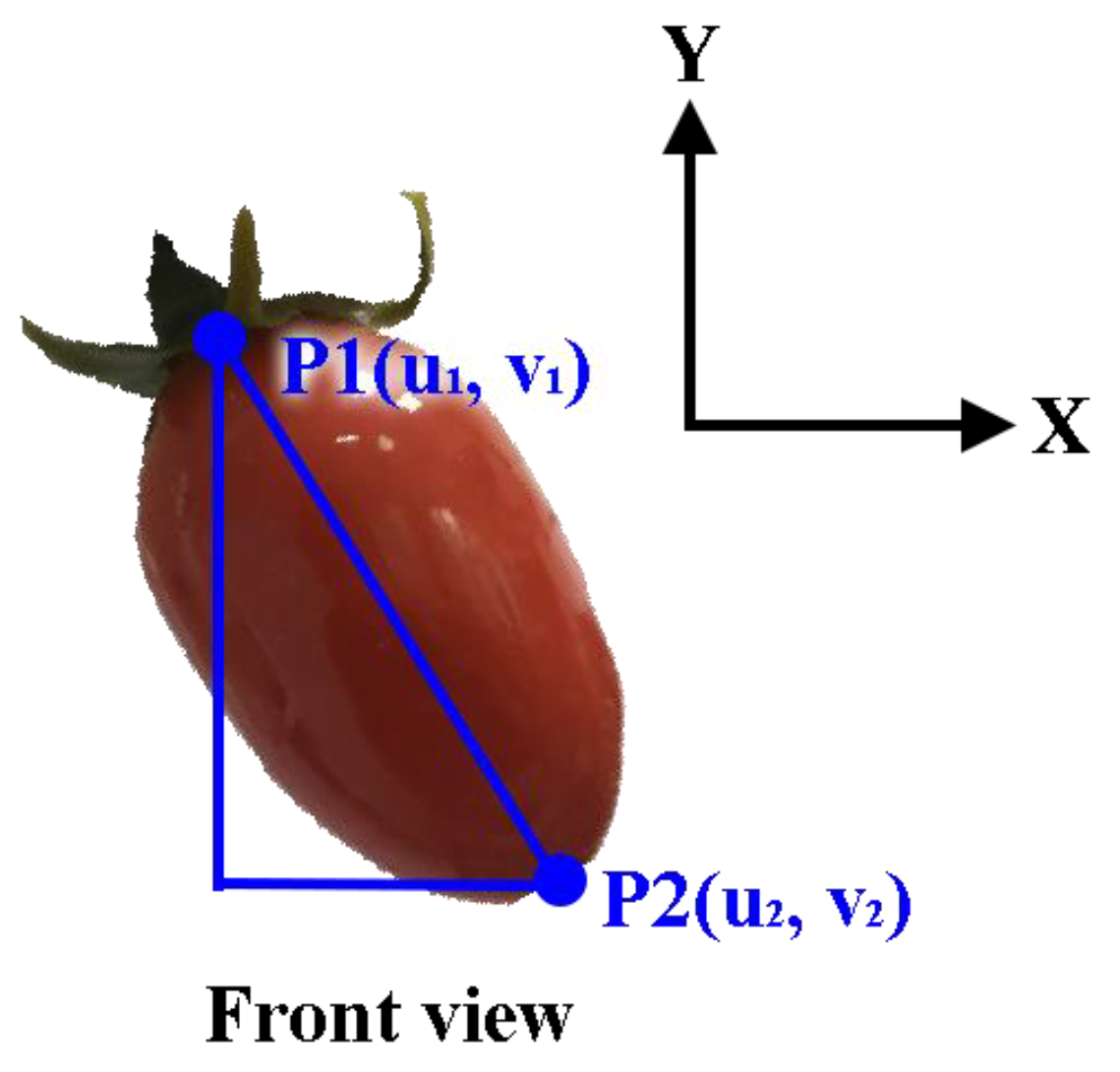
The proposed image processing permits us to further find geometric feature points to recognize the status and orientations of the target cherry tomatoes. To identify the orientations of cherry tomatoes, the centroid of the shape is first determined by an image moment approach [
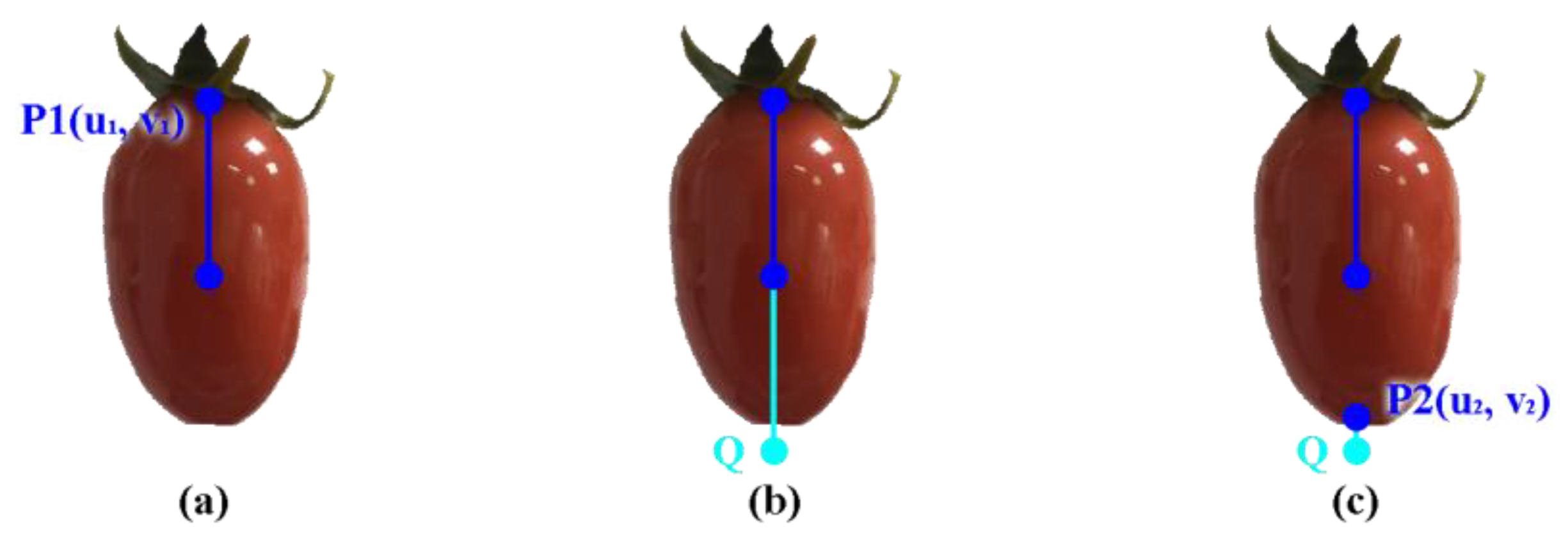
28]. Shape and distribution can be obtained by calculating the moments of an image. Furthermore, based on moment invariants, features remain unchanged under transformations such as rotation, scaling, and translation. As a result, the center point of the image is inferred by the central moments as shown in
Figure 4a for the centroid of the cherry tomato. The point P
1(u
1, v
1) on the contour of the ellipse with the maximum distance from the centroid is detected and defined as one of the endpoints of the major axis of the ellipse. Taking the equal length to P
1C to obtain the point Q, the point Q must be located outside of the ellipse, as shown in
Figure 4b. And hence it may not be the other endpoint of the major axis. By searching the points along the contour of the ellipse, the closest point P
2(u
2, v
2) to Q will become the other modified endpoint of the major axis of the ellipse, as shown in
Figure 4c. These feature points are extracted to further recognize a tomato’s posture for reliable harvesting.
2.4. Pose of the Cherry Tomato
The control and motion guidance of a robotic manipulator for target cherry tomato harvesting are influenced by the targets’ poses in space. In general, the orientation of a fruit can be suitably expressed in spherical coordinates with respect to the image plane. The parameters describing the status of a fruit are the length
l of the major axis and two angles,
and
, respectively, referred to as the polar and azimuthal angles. As shown in
Figure 5, the polar angle
is the angle between the x axis and the projection of the major axis on the image plane and can be determined using the extracted feature points P
1 and P
2 as
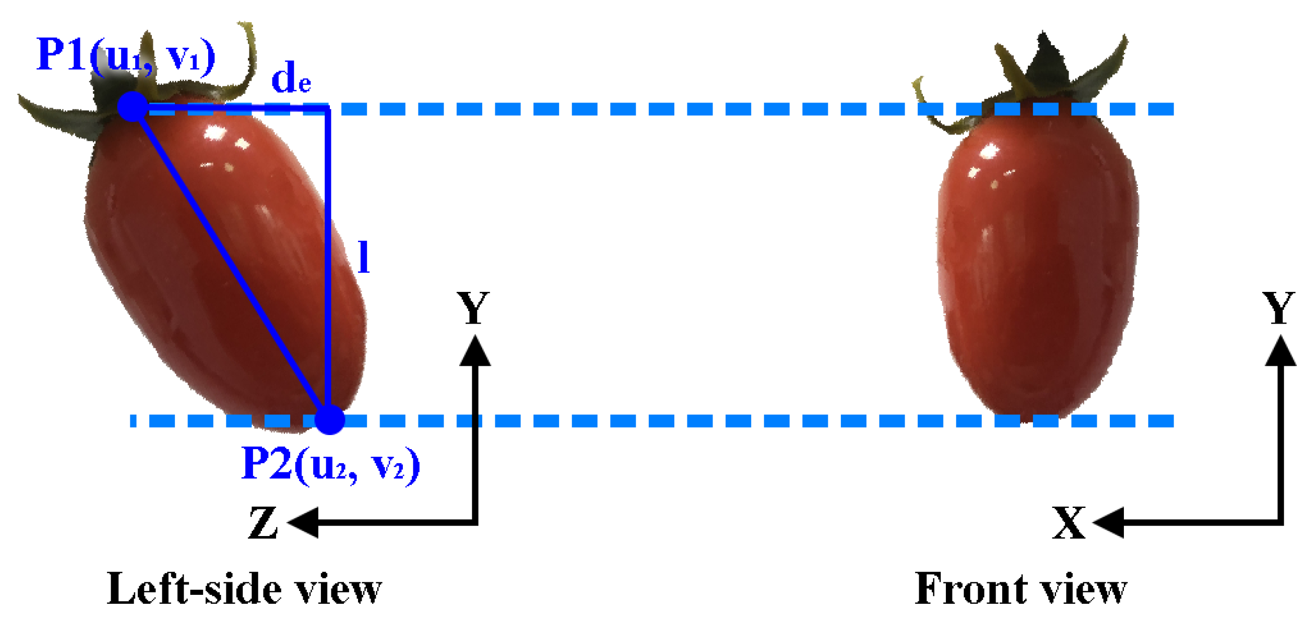
The azimuthal angle is defined as the angle between the actual major axis and the y axis. As shown in
Figure 6, the azimuthal angle can be determined by the projected length
l of the actual major axis onto the image plane and the depth difference
of both feature points P
1 and P
2 in the z direction such that
in which the depth difference
=
, with
being acquired by the depth camera of the visual system. The projected length
l =
is the difference of the y coordinates of the two feature points in the image frame.
3. Visual Servo Controller for the Robotic Manipulator
A harvesting robotic manipulator must be capable of searching for a target and then driving to the desired position for the ensuing actions. Therefore, machine vision must be installed for visual servo control to realize the point-to-point localization. So, in this section, the visual servo control design will be presented for fruit picking.
3.1. PBVS for Cherry Tomato Harvesting
A PBVS is usually referred to as a 3D feedback control in the inertial frame. Features are extracted from the image to estimate the pose of the target tomato with respect to the camera. In this way, the error between the current and the desired pose of the target in the task space can be used to synthesize the control input to the robotic manipulator.
In the PBVS control method, the target is identified by the color depth camera with respect to the base frame. The image-expressed information is first processed and then converted to the position with respect to the camera frame according to the ideal pinhole camera model and further transformed to the coordinates with respect to the base frame using the relationship between the object frame and the camera frame. As such, the transformation from the coordinates of the object point (
X, Y, Z) expressed in the base frame to the corresponding image point (
u, v) is written as
in which
A is the camera intrinsic matrix, with
A =
representing the relationship between the camera frame and the image frame. It can be obtained through measurement or calculation using the given FOV;
and
are the effective focal length in pixels of the camera along the
and
axes; γ is the camera skew factor, and (
,
) indicate the difference between the camera center and the image center. In addition, the extrinsic coordinate transformation matrix
B =
expresses the relationship between the object frame and the camera frame with
being defined as the rotational matrix and
t as the translational displacement from the camera to the object. The rotational matrix
can be determined from the equivalent angle-axis representation that is constructed by the polar and azimuthal angles, as discussed in
Section 2.4.
To harvest cherry tomatoes with camera alignment control, PBVS first serves as a coarse alignment and is then followed by IBVS for image-based fine alignment control. The coarse alignment control will enable the manipulator to move to a desired operation position ready to cut. The desired operation position is assigned as (, ) near the principal point of the image plane. The corresponding desired position with respect to the base frame is determined as noted above. Since the rotation of the tomato around its central axis is considered invariant, only these two angles between the tomato central axis and the x and z axes are taken into account.
Utilizing the pixel error values, the depth values obtained from the depth camera, and the external and internal parameter matrices, the translational displacement is thus calculated. The PBVS control for cherry tomato harvesting is shown in
Figure 7.
3.2. IBVS for Cherry Tomato Harvesting
IBVS calculates the control input to the manipulator directly using image feature errors to reduce computational delay and thus is less sensitive to calibration. The control design of IBVS and the selections of the associated control gains need to be examined in an image Jacobian matrix that relates the feature velocity to the camera velocity in an image coordinate. Let
and
be the linear velocity and the angular velocity of the camera expressed with respect to the camera frame. The image Jacobian matrix
L of a point P(
X,
Y,
Z) in the camera frame with the corresponding projected coordinate in image space P(
u,
v) can be written as [
29]
For feedback control by IBVS for the robotic manipulator, the errors in the image frame are required. If the desired image position is defined as (
,
) = (
,
), the desired depth distance of the centroid
and (
) are referred to as the desired polar and azimuthal angles. Conventionally, six control errors should be defined in the image space for feedback control. However, the amount of rotation about the principal axis does not affect the picking motion due to our harvesting mechanism design. So, one may define the five errors of feedback control of the robotic manipulator for harvesting as follows:
These five errors that encompass three main feature points, i.e., the two end points , and the centroid point in the pixel plane, are used to compensate for the alignment positioning and orientation errors during the reaching and harvesting phase. The basic visual controller design for a conventional IBVS almost employs proportional control to generate the control signal. However, this method cannot have a faster control convergence and a smaller error. In this paper, a PD control with fuzzy gains is adopted to improve the visual feedback quality.
The proposed PD control scheme in the alignment of the tomato centroid to the center position of the image plane is described as [
30]
in which (
is the translation velocity relative to the current camera frame;
,
,
i = 1, 2, are positive gains. Taking the derivative of Equation (5) and from the image Jacobian matrix, Equation (4), along with the controller, Equation (9), the error dynamics are obtained as
It is seen that the controller in Equation (9) drives the errors to zero.
Moreover, to reach the desired depth
for the centroid of the cherry tomato and to rotate the end effector for the harvesting, the PD control law is used when
=
= 0
Following the above procedures, the error dynamics for the depth, polar, and azimuthal angle are, respectively, derived as
The stability is examined by formulating a Lyapunov function as
V =
, and then taking a derivative of the function, one leads to
If the gains , , , , , are chosen larger than zero, and 0 < < 1, the asymptotic stability is guaranteed. Thus, the steady state errors (, , ) are driven to zero.
3.3. Adaptive Fuzzy Gains for IBVS
In the PD type of IBVS, the control gains
,
,
i = 1,…, 5 are constants that are determined from the Lyapunov stability theorem. However, the control gains can be further determined dynamically to improve the visual feedback performance of the robotic harvesting manipulator. In this regard, a fuzzy inference system based on the Mamdani fuzzy theory [
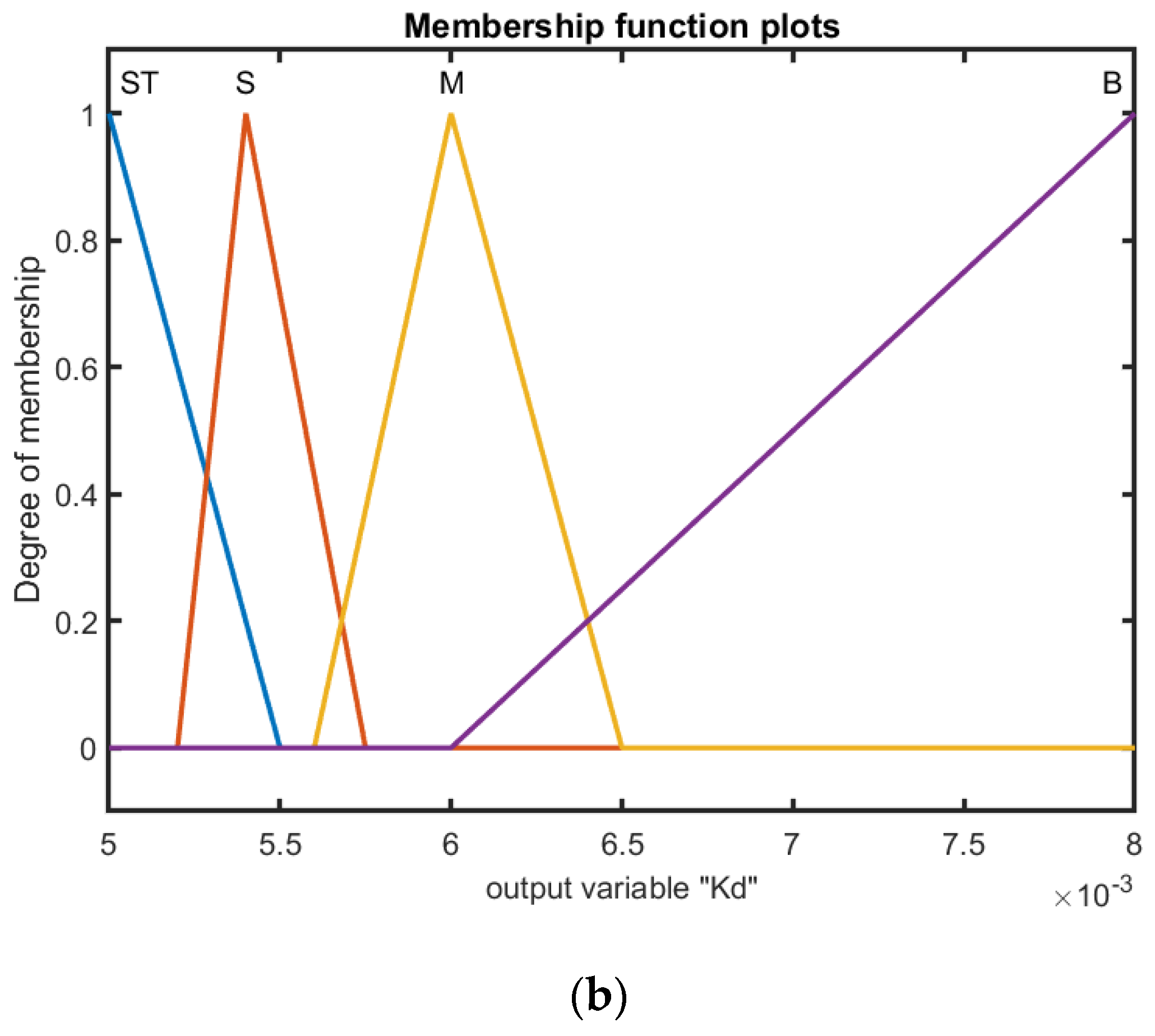
31] is proposed for the design of the gains. Seven fuzzy partitions for the two error inputs
,
and outputs
,
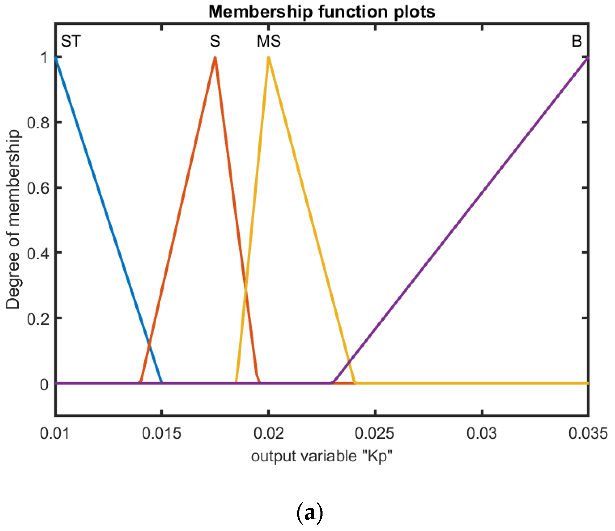
are, respectively, denoted to perform fuzzy reasoning according to the rules in the fuzzy rule base. From the stability proof and many trials, the corresponding membership functions of input and output linguistic variables are presented, respectively, in
Figure 8 for the control gains
,
. In addition, the triangular membership functions were adopted because of their simplicity and computational efficiency. The input–output relationships in the fuzzy inference system are determined as shown in
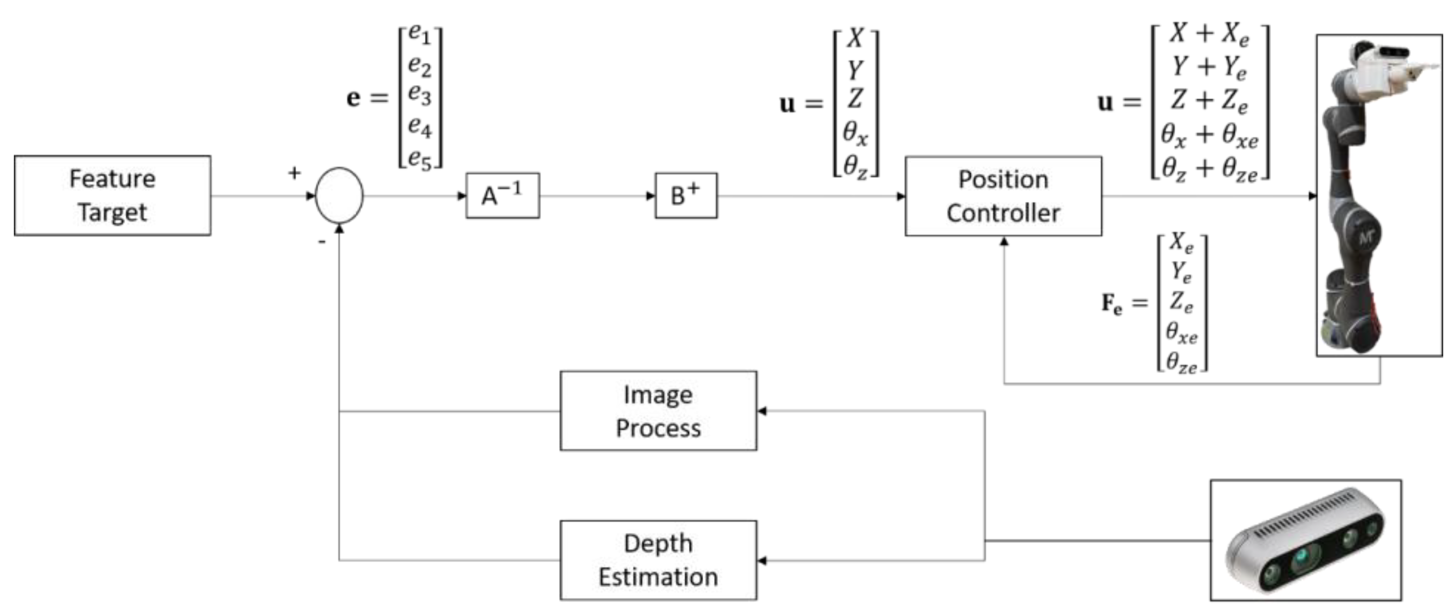
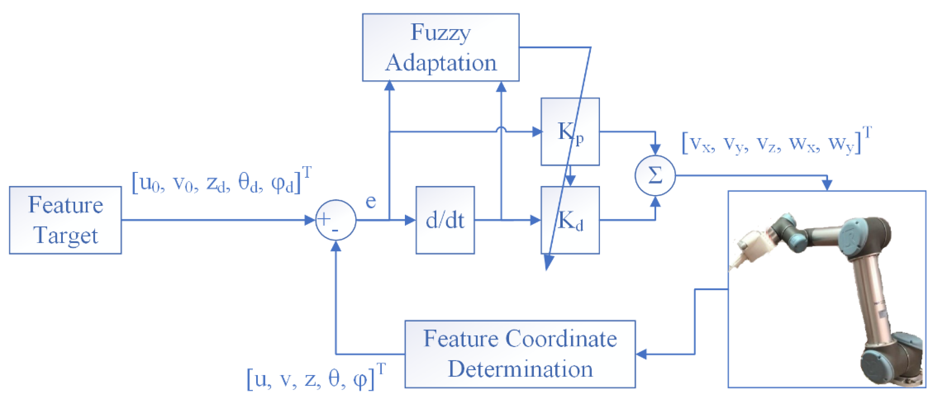
Table 1 based on the fuzzy logic IF–THEN rule base. The centroid defuzzification- based correlation-minimum inference is used for the fuzzy implications, and thus the corresponding control gains can be adjusted adaptively according to the tracking errors and the corresponding rate errors. The whole IBVS control structure is shown in
Figure 9.
3.4. HVSC Algorithm
As mentioned in the preceding, PBVS makes use of a depth stereo camera to identify the target, and then the associated position is calculated by converting the desired point in the image frame to spatial coordinates. However, the conversion may result in an uncertain error because of the intrinsic and external camera parameters. Also, in the process of traveling, the position errors of the end effector will cause a serious localization deviation due to unexpected external disturbances. The errors of position are even accumulated more and more with the traveling distance. IBVS takes advantage of pixel coordinates in the image plane for feedback control without conversion to spatial coordinates, and thus the required calculation loading is comparatively lessened. Moreover, the target information is constantly returned for feedback control while traveling, so it has a higher localization accuracy than PBVS under the identical disturbances. However, the pixel-based control may cause the robotic manipulator to generate a larger response in space. The main drawback of IBVS using a fixed camera is the limited field of view. When the robotic manipulator rotates, the target may be out of the field of view, and the IBVS will fail to control the manipulator. Therefore, an HVSC integrating PBVS and IBVS was proposed for the tradeoff.
As HVSC is applied to cherry tomato harvesting, the PBVS is first executed for the point-to-point coarse localization of the end effector for efficiency. Afterwards, IBVS will be implemented to continue the ensuing movement to reach the desired operation position. Then, the remaining cutting task is performed by the PBVS again. The switching mechanism between PBVS and IBVS is under the following conditions:
- (1)
PBVS is first executed for the point-to-point localization until the prescribed condition , , .
- (2)
The mechanism switches to the fuzzy-based IBVS to continue a fine alignment to the desired operation position.
- (3)
When the target cherry tomato is aligned, the mechanism switches to PBVS to execute cutting off the fruit stem.
4. Experimental Results and Discussions
As shown in
Figure 10, the proposed visual servo control algorithms for cherry tomato harvesting were demonstrated by the robotic manipulator. The laboratory-based experimental field as shown in
Figure 1 was set for the implementation of harvesting, in which an artificial cherry tomato is installed on stainless steel wires with supposed different growth angles.
4.1. Point-to-Point Localization for Target Tomato Manipulation
The proposed PBVS, IBVS, and HVSC were tested for point-to-point localization of a target tomato. The artificial cherry tomato was laid out with the pose angles = = 0. The position of the centroid in the image plane is located at (222, 141) pixels, and the initial depth from the image is 322 mm. The operation location is denoted at the location (320, 240) pixels in the image plane and at a depth of 370 mm. Due to the presumed pose angles, the robotic manipulator will be controlled to reach the operation position without considering the orientations of the end effector.
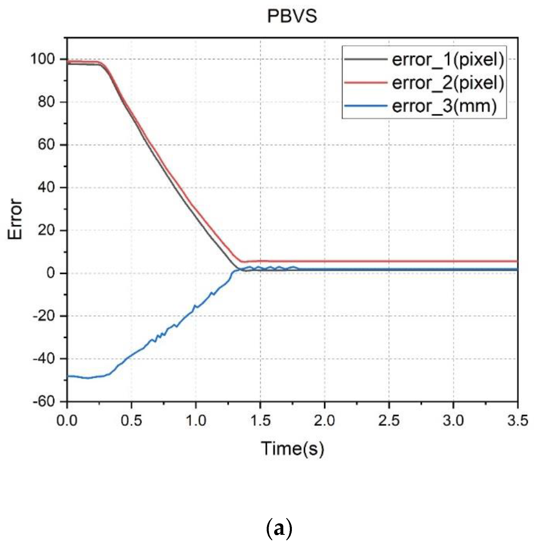
The errors
,
, and
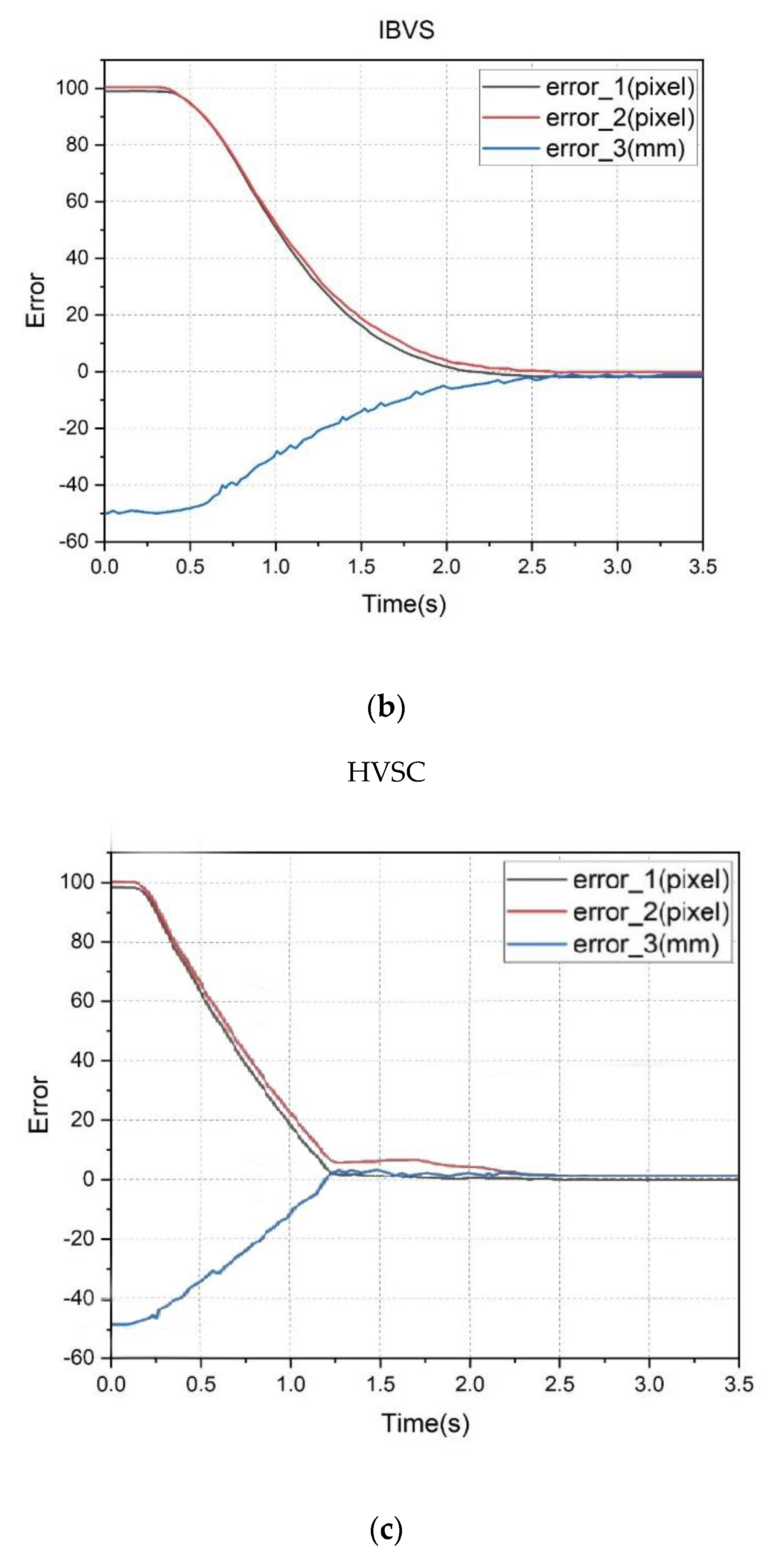
by the three visual feedback controllers are presented in
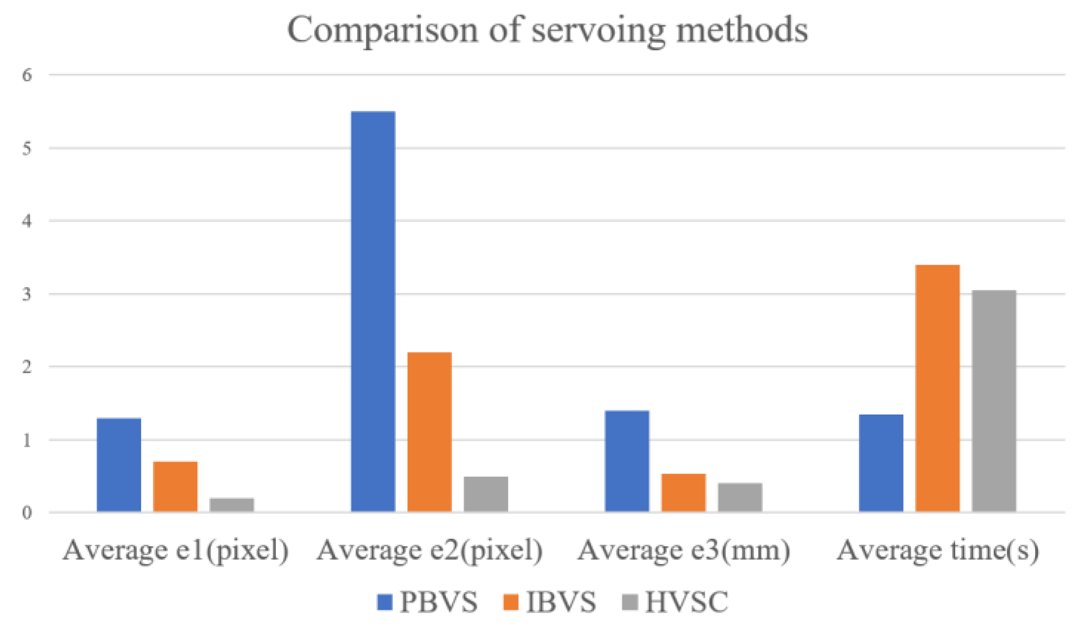
Figure 11. It is shown that the three controllers can effectively align the target and reach the operation position. Their performances were compared as shown in
Figure 12. The PBVS has larger errors in
,
, and
because of the camera parameters’ uncertainty and measurement errors that lead to inaccuracy in the coordinates of the target in space. However, the PBVS has a shorter execution time because the PBVS need not frequently capture images to serve as feedback information.
4.2. HVSC with Constant and Fuzzy Feedback Gains
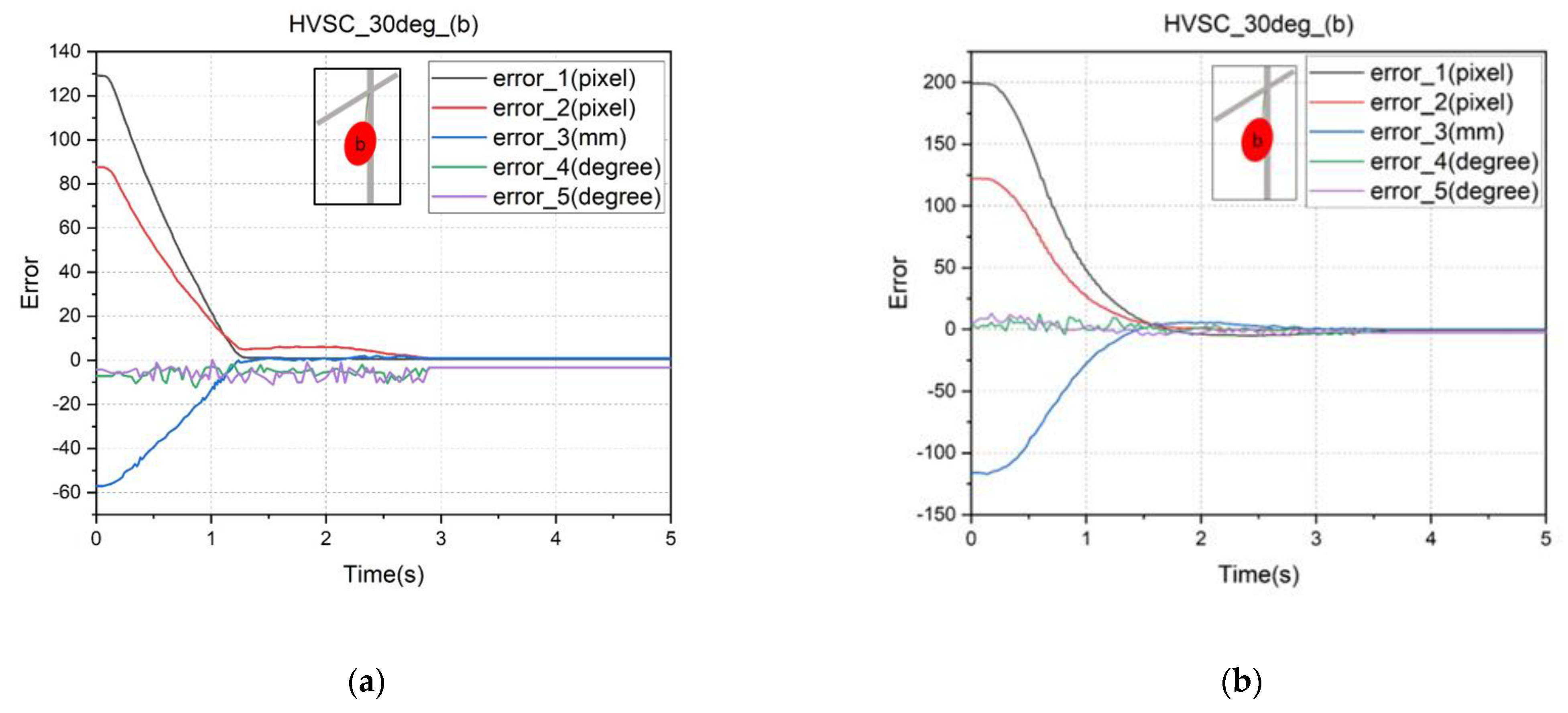
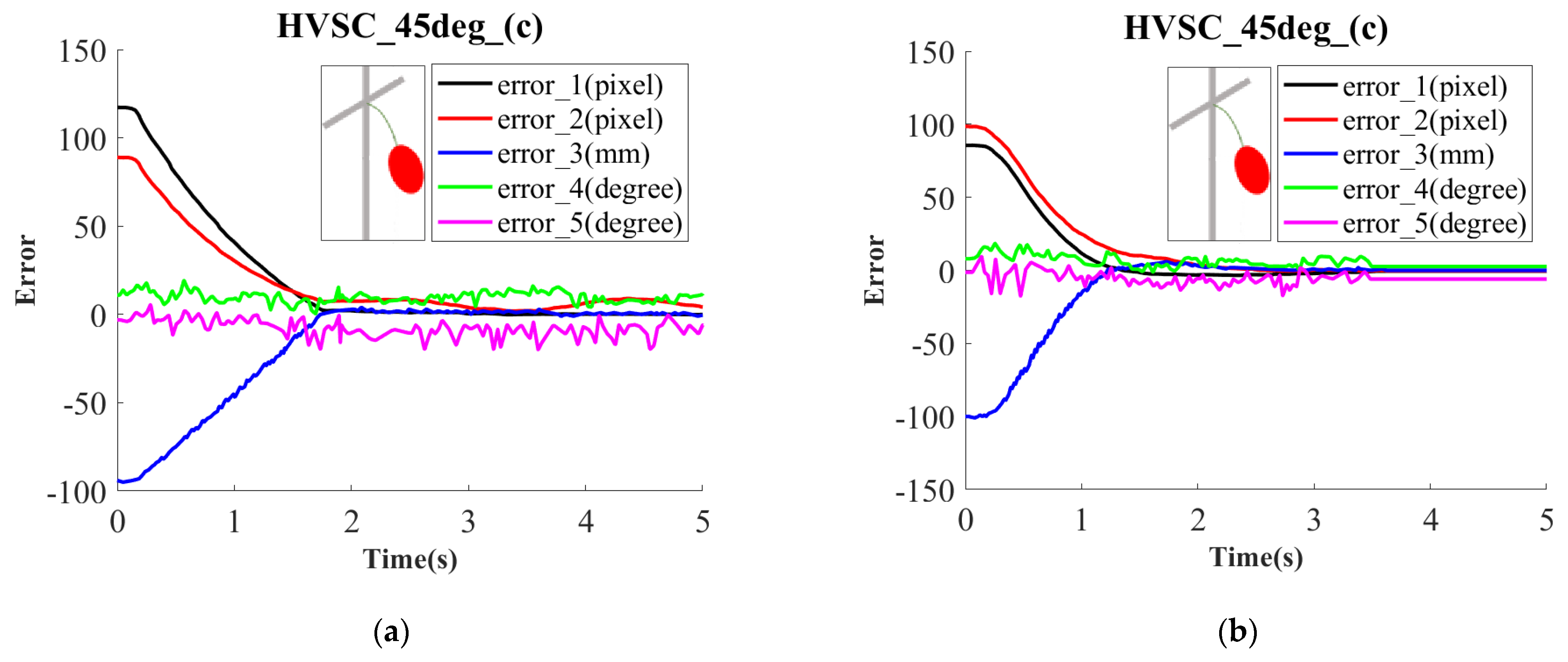
In this subsection, the HVSC with a separation constant and fuzzy feedback, respectively, were performed and compared for target localization with varied poses. The results for reaching the operation position are presented in
Figure 13 with
,
and
Figure 14 with
,
. Even when the target has a far distance from the end effector, it is seen that the HVSC with fuzzy feedback gains has better stabilization than the constant gains, due to robusticity against disturbances. In addition, the performance for larger pose angles may engender a larger localization deviation because the larger pose angles are difficult to compute and identify accurately.
4.3. Application to Cherry Tomato Picking
Finally, the artificial target cherry tomatoes were picked by the proposed robotic manipulator with the fuzzy-based HVSC. After identifying the tomato and determining the corresponding position and orientation, the harvesting mechanism moves to the operation position using the HVSC. According to the harvesting mechanism design, if the rectangle sleeve can successfully capture the target cherry tomato, the object must be picked without needing accurate positioning. Also, PBVS has a comparatively fast execution speed, so the visual control was switched to PBVS to pick the target following HVSC.
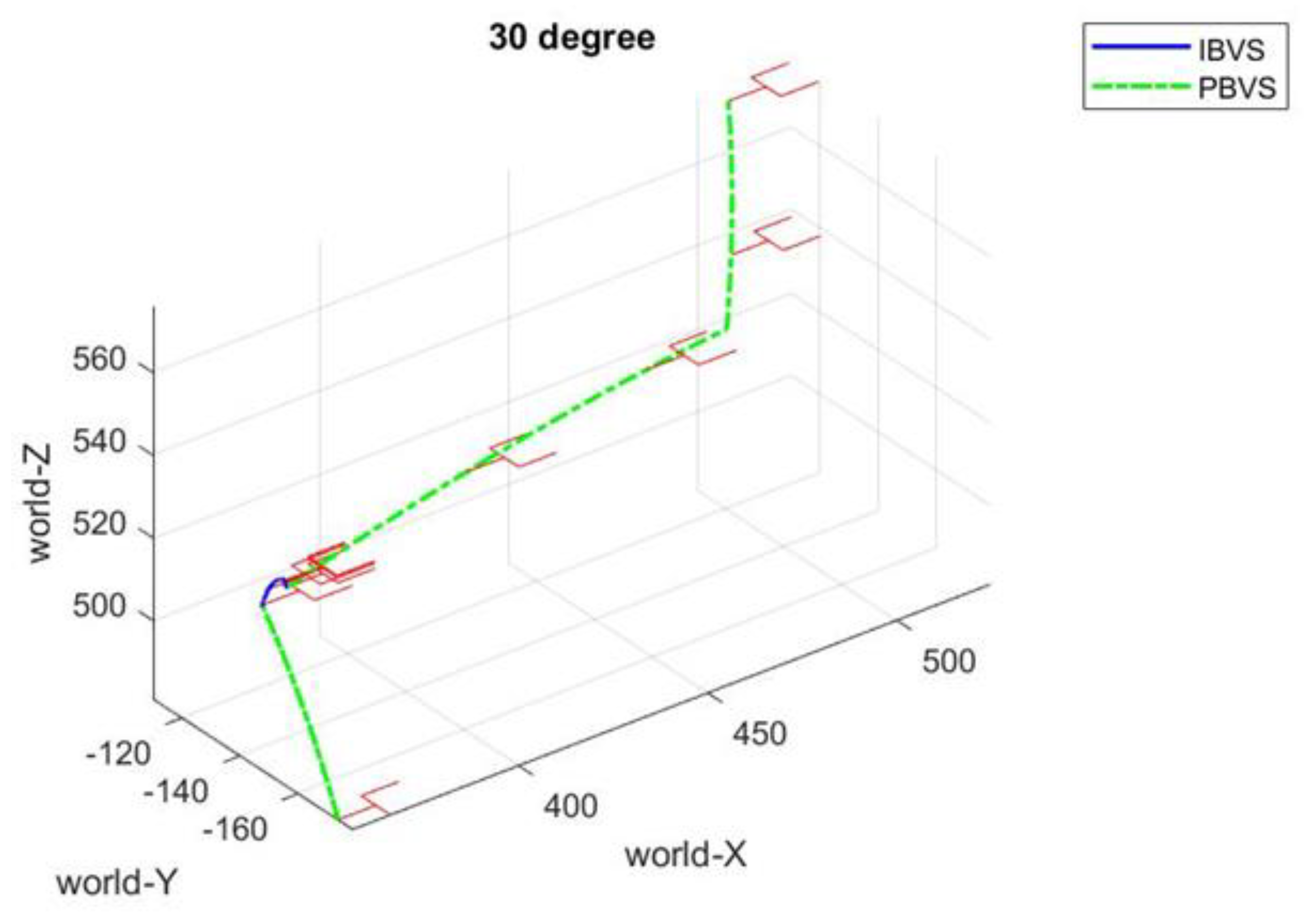
Figure 15,
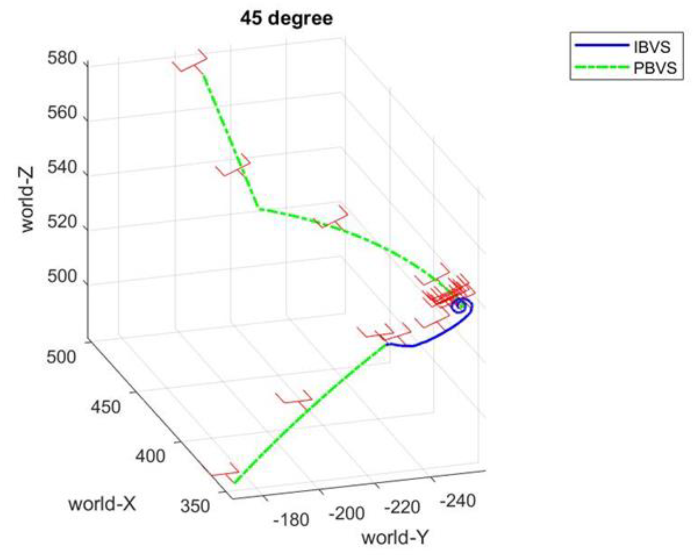
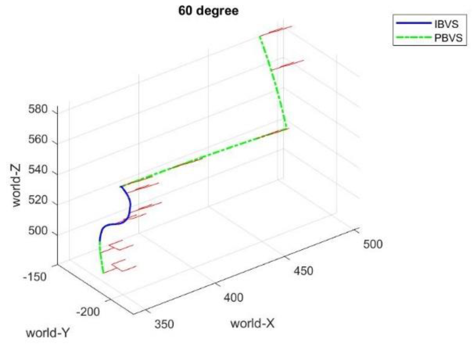
Figure 16 and
Figure 17 depict the harvesting trajectories in space for target tomatoes with growth orientations
,
, and
. Initially, the surface of the rectangle frame is parallel to the ground. For the growth pose
and
, the orientation of the end effector does not adjust very much while moving for picking. However, in the case of
of growth pose, it is apparent that the orientation of the end effector must be varied to pick the cherry tomato successfully. Moreover, based on numerous tests for each case, it is demonstrated that the picking success rate is 100% for
of growth pose and 94.5% for
of growth pose, while the picking success rate for
is the lowest with 89.2%. The reason results from the large computational errors for a target cherry tomato with a large angle for growth orientation.
5. Conclusions
This paper concludes with the realization of a robotic manipulator for cherry tomato harvesting. To perform smooth and accurate localization tasks, the fuzzy-based HVSC was used to implement the point-to-point localization and picking tasks, in which the PBVS was first performed for the coarse localization of the end effector, and the IBVS was then executed to drive the end effector to the desired operation position. Finally, the robotic manipulator was again switched to the PBVS to perform the cherry tomato picking using our developed cutting and clipping integrated mechanism. The laboratory experiments for different poses of artificial cherry tomatoes demonstrate the feasibility of the proposed robotic manipulator and visual servo control for cherry tomato harvesting. The overall results show that the developed robotic manipulator using fuzzy-based HVSC has an average harvesting time of 9.40 s/per and an average harvesting success rate of 96.25% in picking cherry tomatoes with random pose angles. The picking failures always result from the noise on the measured depth values and the associated computational pose errors such that the sleeve cannot successfully capture the target cherry tomatoes.
In the future, more investigations of factors such as the picking order, occlusion, overlapping, and environmental lighting problems are to be conducted for practical field applications. Further comparative analyses and comprehension of the proposed system in real field tests will be thus evaluated.
