Article

Evolutionary Computation-Based Active Mass Damper Implementation for Vibration Mitigation in Slender Structures Using a Low-Cost Processor

by
César Peláez-Rodríguez
1,2,*,
Alvaro Magdaleno
2,*,
Álvaro Iglesias-Pordomingo
2 and
Jorge Pérez-Aracil
1
1
Department of Signal Processing and Communications, Universidad de Alcalá, 28805 Alcalá de Henares, Spain
2
ITAP, Escuela de Ingenierías Industriales, Universidad de Valladolid. P.º del Cauce, 59, 47011 Valladolid, Spain
*
Authors to whom correspondence should be addressed.
Actuators 2023, 12(6), 254; https://doi.org/10.3390/act12060254
Submission received: 21 April 2023 / Revised: 14 June 2023 / Accepted: 16 June 2023 / Published: 18 June 2023

Abstract

:
This work is devoted to design, implement and validate an active mass damper (AMD) for vibration mitigation in slender structures. The control law, defined by means of genetic algorithm optimization, is deployed on a low-cost processor (NI myRIO-1900), and experimentally validated on a 13.5-m lively timber footbridge. As is known, problems arising from human-induced vibrations in slender, lightweight and low-damped structures usually require the installation of mechanical devices, such as an AMD, in order to be mitigated. This kind of device tends to reduce the movement of the structure, which can be potentially large when it is subjected to dynamic loads whose main components match its natural frequencies. In those conditions, the AMD is sought to improve the comfort and fulfil the serviceability conditions for the pedestrian use according to some design guides. After the dynamic identification of the actuator, the procedure consisted of the experimental characterization and identification of the modal properties of the structure (natural frequencies and damping ratios). Once the equivalent state space system of the structure is obtained, the design of the control law is developed, based on state feedback, which was deployed in the low-cost controller. Finally, experimental adjustments (filters, gains, etc.) were implemented and the validation test was carried out. The system performance has been evaluated using different metrics, both in the frequency and time domain, and under different loads scenarios, including pedestrian transits to demonstrate the feasibility, robustness and good performance of the proposed system. The strengths of the presented work reside in: (1) the use of genetic evolutionary algorithms to optimize both the state estimator gain and the feedback gain that commands the actuator, whose performance is further tested and analyzed using different fitness functions related to both time and frequency domains and (2) the implementation of the active control system in a low-cost processor, which represents a significant advantage when it comes to implement this system in a real structure.

1. Introduction

Recent advances in structural technologies, including new construction materials and more innovative design techniques, promote the trend towards designing lighter, more slender and aesthetically pleasing structures with fewer nonstructural elements [1]. These structures are more cost-effective and architecturally attractive, resulting in very efficient designs. However, from the structural point of view, they exhibit much lower inherent damping and lower natural frequencies than before [2], which increases their dynamic sensitivity and makes them more susceptible to be excited by the occupants, such as pedestrians or traffic [3]. As a consequence, the structural response is sometimes unacceptably high, so their serviceability may be compromised. In this case, one or more vibration mitigation devices, or structural control systems, need to be installed in order to meet the serviceability criteria [4].
Structural control systems are typically divided into four different strategies according to the characteristics of control devices and approaches: passive control, active control, semi-active control and hybrid control [5]. One of the most popular approaches is the passive one, which is usually implemented as a Tuned Mass Damper (TMD) [6,7,8,9]. A TMD is a one-degree-of-freedom mass-spring-damper device whose natural frequency is tuned to match one natural frequency of the structure, so the contribution of the corresponding mode to the overall response is strongly dampened. This system has the advantage of having a minimum cost, due to its small size (its moving mass typically ranges between 0.15 and 1% of the structure mass) and its easy implementation in a existing structure. However, it is only capable of mitigating the response associated with the structural mode it is coupled to, so it still allows a relatively large response to loading containing other frequency components, such as impulse or random forces. When high performance is required, it is more convenient to use an active control device [10]. These systems are able to adapt the response of the structure during dynamic loads, applying control actions at each instant in response to the load, reaching high levels of efficiency in vibration mitigation. In addition, active systems enable to simultaneously mitigate the contribution of several vibration modes with a single device, which makes this system an interesting solution for reducing the response of low damping flexible structures characterized by several modes of vibration which significantly contribute to the overall response. Furthermore, active systems are versatile, have no tuning problems and can be unconditionally stable if a properly designed control system is implemented [11]. However, active control may not be an attractive solution in terms of cost because it requires a higher level of technology and maintenance than other control approaches. Furthermore, it often requires expensive devices as well as power supply systems, and may have reliability problems under certain circumstances. For the design of an active control system, two critical issues need to be considered. The first one is the necessity of developing a control algorithm which must be robust enough to compute the control force in real time; otherwise, instabilities may occur and potentially fatal damage would be induced to the structure. The second issue relates to the need for a high-performance actuator capable of applying the desired control force on the structure in real time with an admissible error [12].
With regard to the control strategy, most of the approaches rely on a feedback schema [13]. The principle of feedback control consists of comparing the system output (y) with a reference signal ( y ^ ), obtaining the error signal, e ( e = y y ^ ). This signal is then transmitted to a control device (compensator), which has implemented the required algorithm to transform the error values into a signal to appropriately command the actuator. The design problem in this control schema is to find the right compensator so that the closed-loop system is stable and behaves optimally. Several active control strategies have been proposed and reviewed in the literature [13,14,15], with the Direct Velocity Feedback (DVF) [16,17,18] and the Feedback State Control [19,20,21] being among the most commonly used. These methods use some structural response information and produces a set of control forces that influence the dynamical response of the structure. One of the most compelling approaches in this regard is the optimal control, in which the operating parameters are determined so as to optimize a given evaluation function [22]. Most optimal control design techniques are based on an optimization strategy to maximize system performance by minimizing the control energy under certain constraints, or by minimizing the response magnitudes of the structure. The optimization procedure can be briefly described as the tuning of the control system parameters [23]. The linear-quadratic regulator (LQR) is one of the most commonly used methods, and has been extensively investigated in the literature [24,25,26,27,28]. The LQR designs a state-feedback gain by minimizing a performance index that contains a weighted state and control input. Furthermore, several evolutionary computation and metaheuristic optimization algorithms have been implemented to tackle the problem of control parameter optimization [29,30,31,32,33,34,35,36,37].
In this context, feedback state control has been implemented in this paper, where the position and velocity of the structure are considered the state variables. However, as these states are not measurable in the actual application, as only accelerometers are installed in the structure, a state estimator is necessary. This could increase the computational effort and lead to time delay in the control loop. To avoid this, a genetic evolutionary algorithm (GA) has been implemented to efficiently find an optimal solution for both the controller and the state estimator parameters. Genetic algorithms have been applied as effective search techniques to many fields of optimization problems [38,39], and have been successfully applied to obtain gains for the optimal controller, reduce the order of the feedback controller or tune the weights of neuro-controllers [40,41,42]. Regarding the actuator used to apply the feedback forces in the structure, an active mass damper (AMD) has been used, which is one of the most commonly used actuators to apply forces to mechanical systems [15,43,44,45,46,47,48], since they can be placed in the most favorable positions regarding the most significant vibration modes and can be easily concealed within the structure. Furthermore, a novelty of the presented work resides in the use of a low-cost processor (NI myRIO-1900) to implement the control law, which represents a significant advantage when it comes to put into operation this system in a real structure. The system performance has been evaluated using different metrics both in the frequency and time domain and under different loads scenarios, including pedestrian transits to demonstrate the feasibility, robustness and good performance of the proposed system. The strengths of the presented work lies in: (1) the use of genetic evolutionary algorithms to optimize both the state estimator gain and the feedback gain that commands the actuator using different fitness functions related to both time and frequency domains and (2) the implementation of the active control system in a low-cost processor, which represents a significant advantage when it comes to implement this system in a real structure.
The rest of the paper is organized as follows: Section 2 details the computational algorithms employed throughout the paper, along with the characteristics of the test structure and the hardware used in the implementation of the active vibration mitigation system. Section 3 describes the control algorithm used. Then, Section 4 describes the system deployment in the low-cost controller and shows the experimental validation of the system. Finally, some discussions and conclusions, together with suggestions for future work, are given in Section 5.

2. Materials and Methods

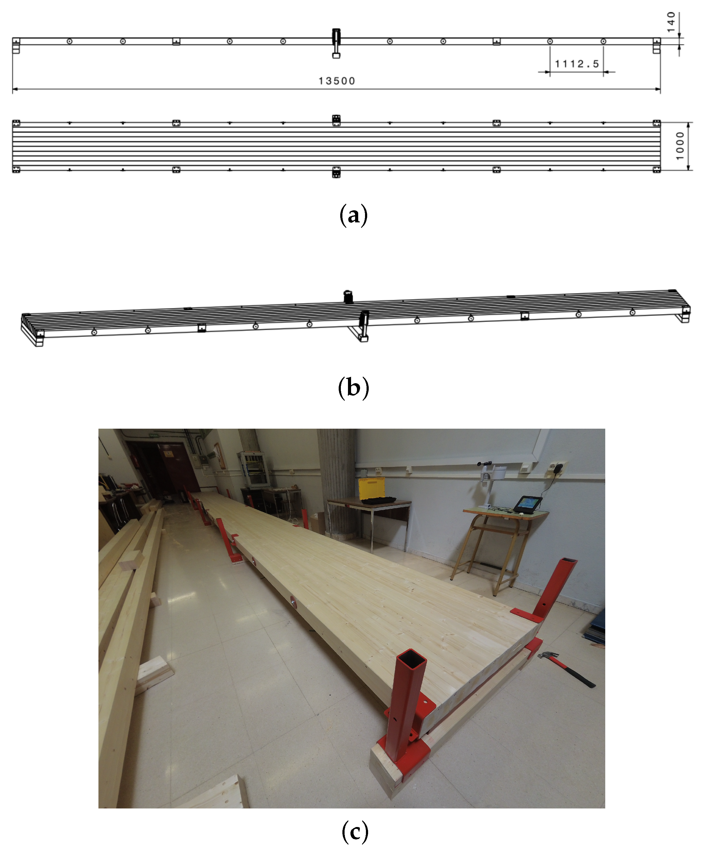
This paper presents the design and practical implementation of an inertial mass-based active damping device, in order to cancel excessive vertical vibrations on a lab-scale footbridge. Experimental validation of this system was performed on a 13.5 m long wooden platform (Figure 1), designed for its first natural frequency to be around 2 Hz, so that it can be excited by walking. The developed system is focused on the vibrations mitigation in a range close to the first natural frequency, considering the structure as a single degree of freedom system. The control law of the feedback control system, as well as the the state estimator, have been designed using evolutionary optimization algorithms to minimize the response of the closed-loop system. A commercial electrodynamic inertial actuator (APS 400 ELECTRO-SEIS) with a moving mass of 31.2 kg, controlled by a low-cost processor (NI myRIO 1900), is used as the actuator of the AMD.
This section provides further information about the evolutionary optimization algorithm employed in the execution of this work (Section 2.1), and thoroughly details the characteristics of the test structure (Section 2.2) and the hardware used in the implementation of the active vibration mitigation system (Section 2.3).

2.1. Basic Structure of a Genetic Algorithm

The genetic algorithm (GA) is a well-established optimization algorithm inspired by natural selection, which was first proposed by [49]. It is a population-based search algorithm, which makes use of the concept of survival of fittest. The basic idea is to maintain a population of chromosomes (representing candidate solutions to the specific problem being solved) that evolves over time through a process of competition and controlled variation. A GA starts with a population of randomly generated chromosomes, and advances toward better chromosomes by applying genetic operators based on the genetic processes occurring in nature. The population undergoes evolution in a form of natural selection. During successive iterations, called generations, chromosomes in the population are rated for their adaptation as solutions, and on the basis of these evaluations, a new population of chromosomes is formed using a selection mechanism and specific genetic operators, such as crossover and mutation. An evaluation or fitness function must be devised for each problem to be solved. Given a particular chromosome, a possible solution, the fitness function, returns a single numerical fitness, which is supposed to be proportional to the utility or adaptation of the solution represented by that chromosome [23,38]. The chromosome representation, fitness function computation, selection, crossover and mutation are the key elements of GA. The procedure of GA is depict in the pseudo-code shown in Algorithm 1.
Algorithm 1 Genetic algorithm (GA)
  • Input :
  • Population size , n
  • Maximum number of iterations , M A X
  • Output :
  • Global best solution , Y b
  • begin :
  • Generate initial population of n chromosomes Y i ( i = 1 , 2 , , n )
  • Set iteration counter , t = 0
  • Compute the fitness value of each chromosomes
  • while ( t < M A X ) :
  • Select a pair of chromosomes from initial population based on fitness
  • Apply crossover operation on selected pair with crossover probability
  • Apply mutation on the offspring with mutation probability
  • Replace old population with newly generated population
  • Increment the current iteration t by 1
  • end
  • return the best solution , Y b
  • end

2.1.1. Chromosome Representation

This procedure consists of the encoding of a given information to a particular bit string that the GA can manage [50]. The encoding schemes are differentiated according to the problem domain. In this work, binary encoding is employed, since it provides faster implementation of crossover and mutation operators [51]. Each gene or chromosome is represented as a string of 1 or 0. In this encoding scheme, each solution is represented by an n 0 -bit-long chromosome, where n 0 represents the length of the bit string required to represent each design variable. It can be determined according to Equation (1), where U and L represent the upper and lower bounds of the variable, respectively, p denotes the required decimal precision and r depicts the number of bits used to represent the design variable:
2 ( r 1 ) < ( U L ) · 10 p < = 2 r

2.1.2. Fitness Function Computation

The GA uses a function value for the selection of the operator; this function reflects the objective and a penalty for constraint violation. Since the GA has been used on several occasions throughout this paper, the fitness functions employed are detailed further.

2.1.3. Selection

Selection is an important step in genetic algorithms that determines whether the particular string will participate in the reproduction process or not. The Stochastic universal sampling (SUS) [52] technique has been selected in this work. It uses a random starting point in the list of individuals from a generation and selects the new individual at evenly spaced intervals. It gives equal chance to all the individuals in getting selected for participating in crossover for the next generation.

2.1.4. Crossover

The crossover operator is used to produce two offspring from the genetic information of the selected parents. To select the parents for crossover from the new population, a random number between 0 and 1 is generated. If this random number is less than the probability of crossover, then the chromosomes are randomly paired for crossover. A uniform crossover strategy [53] has been selected. In a uniform crossover, parent cannot be decomposed into segments. The parent is treated as each gene separately. We randomly decide whether we need to swap the gene with the same location of another chromosome [54].

2.1.5. Mutation

Mutation is an operator that maintains the genetic diversity from one population to the next population. The mutation is performed on a bit-by-bit basis, with a certain probability of mutation. This operation is also performed with the help of a random number between 0 and 1. If the random number is less than the probability of mutation, then the bit under consideration will be randomly switched.

2.2. Test Structure

The structure to be used is a timber platform (made of GLULAM 24 h) that is 13.5 m long and 1 m wide. It is made from ten independent beams of 13.5 × 0.1 × 0.14 m, connected by thirteen threaded rods located every 1.11 m. The platform is placed on two fixed supports at both ends. In the central section, six springs (three on each side of the platform, with a stiffness constant of approximately 6600 N/m) are arranged in order to increase the stiffness of the structure.
The system itself is very flexible and low damped, which means that it is prone to oscillate and the response of the structure to disturbances close to its natural frequencies remains high.
The floor plans, a 3D view and a picture of the footbridge are shown in Figure 1. Figure 2 shows the lateral view of its theoretical bending modes, which have been extracted from a preliminary but realistic model of the structure in the finite element software SAP2000 (considering the nominal properties of GLULAM 24 h, Table 1, using volumetric eight-node elements, and assuming the hypothesis of homogeneous material modeling). These theoretical modes are shown as a preliminary reference on the values of the natural frequencies of the structure, and illustrate that: (1) only the first mode will be affected by human activity, since the second and third modes are expected to present too high natural frequencies, and (2) the middle section of the footbridge is the point where the highest modal co-ordinate can be expected from the first mode. Subsequently, in Section 2.2.1, the actual identification of the modes is performed by conducting an experimental modal analysis.

2.2.1. Experimental Modal Analysis

The inertial mass actuator was used to carry out the process of obtaining the experimental frequency response function (FRF) of the structure. A piezoelectric accelerometer was placed on the shaker moving mass (with a value of M = 31.2 kg), so that the applied force can be measured ( F = M a , where a stands for the measured acceleration). A second accelerometer was installed in the footbridge to measure its response. Both the actuator and the response accelerometer were placed in the middle section of the platform. This location was selected by seeking for the point where the highest modal coordinate can be expected from the first mode, as no other point in the structure will best represent this mode. This fact is supported by previous work on this structure [55], where a full modal analysis revealed that the node with the highest response to the first vibration mode is located in the middle section of the platform.
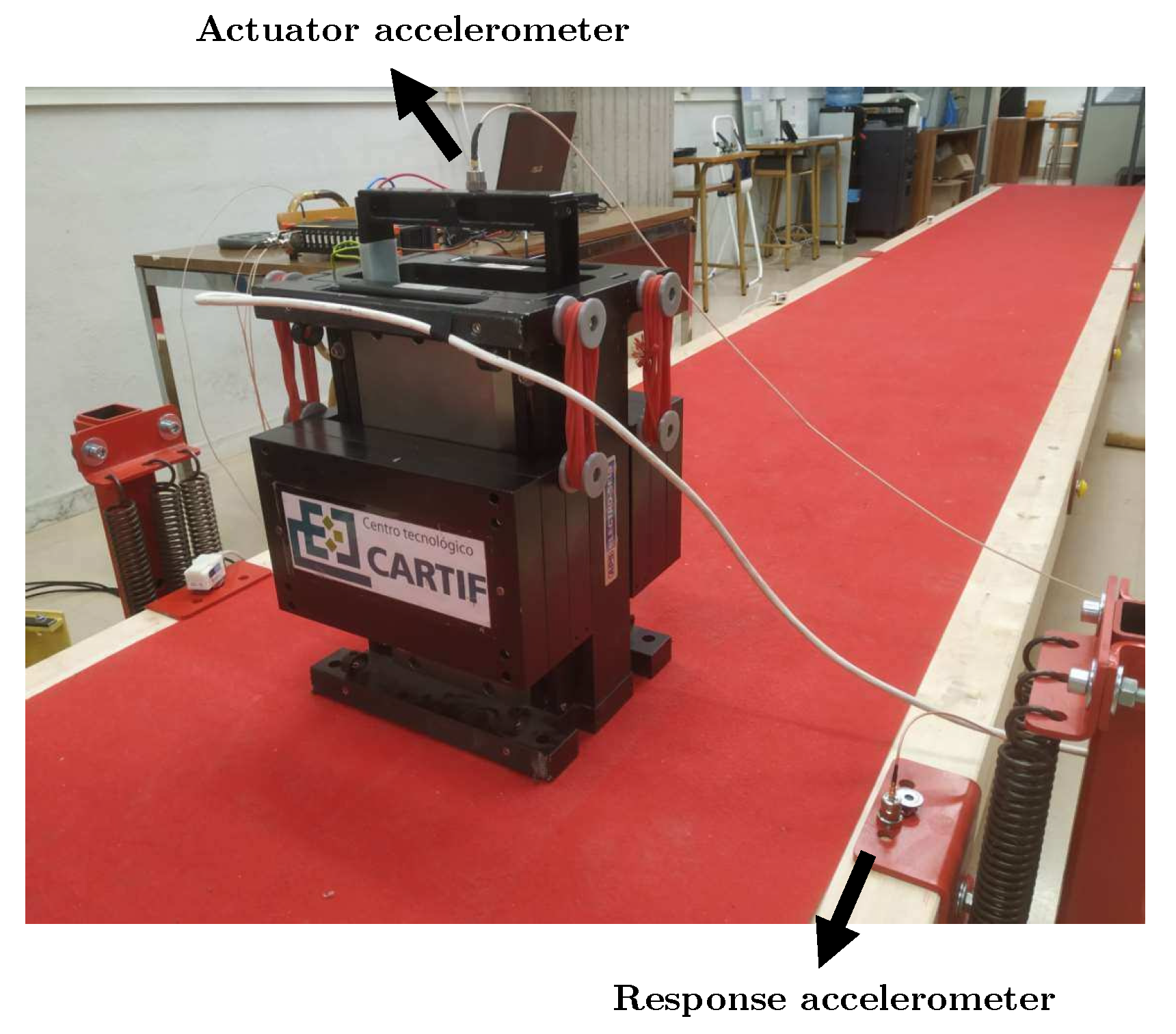
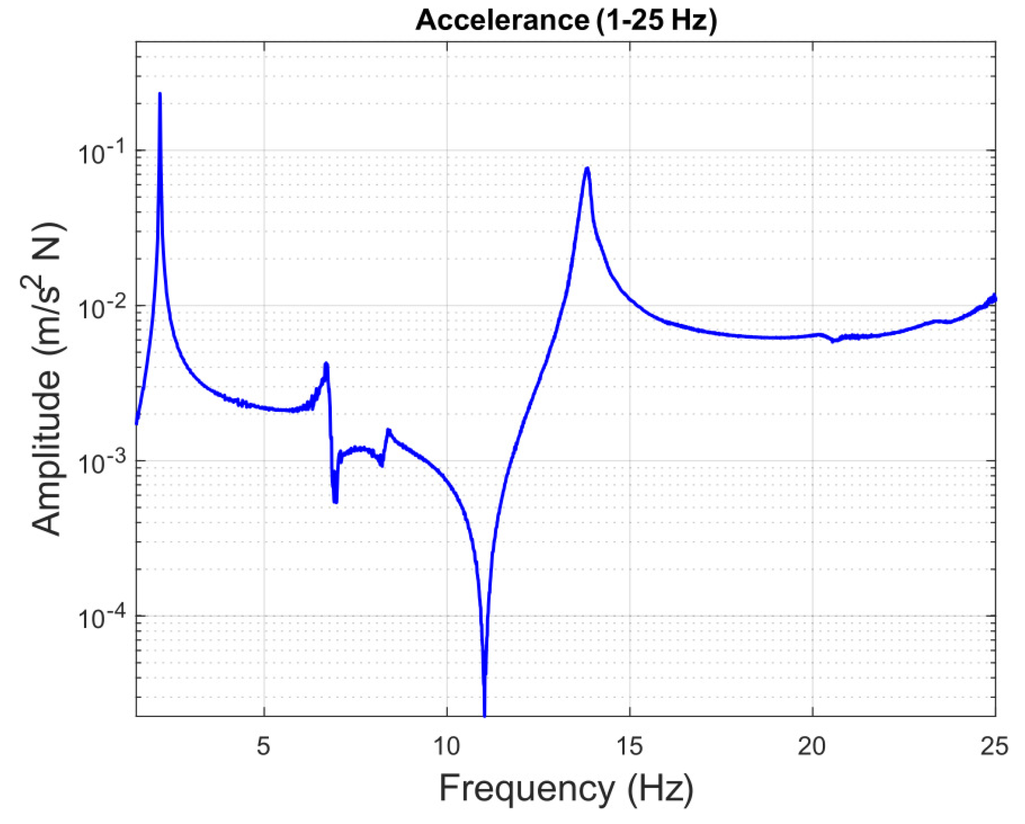
Figure 3 and Figure 4 show the experimental setup used, depicting the position of the shaker and accelerometers in both a schematic top view and a photography, respectively. The shaker (an APS 400 ELECTRO-SEIS) is commanded, through the software implemented in the low-cost processor (NI myRIO 1900), with a white noise signal with an amplitude of ±2 V in a frequency range between 0 and 30 Hz. Data acquisition was carried out using a Dewesoft data acquisition platform, with a sampling frequency of 1 kHz. The registered data were postprocessed using Matlab 2022a software to estimate the experimental FRFs by executing the tfestimate function, selecting a Blackman window with a size of 150,000 points. Figure 5 shows the FRF obtained, representing the system accelerance between 0 and 25 Hz. It can be observed how the peaks of this FRF are sufficiently separated, especially the first one, which is of greater relevance, and located around 10 Hz away from the next one, enough to consider the hypothesis that the behaviour of the structure in a range of frequencies close to its first natural frequency is determined only by this first mode of the structure. Therefore, the platform is modeled by means of a single-degree-of-freedom system corresponding to the first mode of the structure, whose modal properties are obtained in Section 2.2.2. Therefore, the purpose of the presented AMD is to reduce the dynamic response within the range of human excitation, which falls around the structural first mode (1.5–4 Hz).

2.2.2. Modal Property Extraction and Model Generation

A GA optimization algorithm has been used to extract the modal properties of the first mode of the structure, in such a way that the error between the experimental and analytical FRF in the frequency range close to the first mode (1.5–4 Hz) is minimized.
With the aim of determining the analytical frequency response functions of the system, its state space representation was used (Equation (2)), where the input of the system ( f ( t ) ) corresponds with the force applied on the structure, and the output ( y ( t ) ) with the response acceleration that the structure will experience at its midpoint. x ( t ) stands for the vector formed by the state variables of the system, selected to correlate with the position and velocity of the structure’s midpoint (Equation (3)):
x ˙ ( t ) = A s s x ( t ) + B s s f ( t ) y ( t ) = C s s x ( t ) + D s s f ( t )
x ( t ) = u ( t ) u ˙ ( t )
The matrices A s s , B s s , C s s and D s s are chosen to satisfy the equation of motion of the structure according to its modal properties (which is expressed following Equation (4)), assuming, as stated before, that its behaviour can be modeled as a single-degree-of-freedom system. Hence, these matrices are expressed according to the equations presented in (Equation (5)):
u ¨ + 2 ξ 0 ω 0 u ˙ + ω 0 2 u = 1 m f ( t )
A s s = 0 1 ω 0 2 2 ξ 0 ω 0 B s s = 0 1 m C s s = ω 0 2 2 ξ 0 ω 0 D s s = 1 m
Following this process, the three modal parameters were optimized by applying a GA whose fitness function consisted of minimizing the error between the FRF of the experimental system and the one obtained with the modal parameters of each iteration (Equation (6), where n represents the length of the vector of frequencies in which the FRFs are considered, Y denotes the experimental FRF values and Y ^ the simultated ones). The maximum number of generations is set as 50, and the population size at 100. The lower and upper limits of each variables are considered as [ 300 , 1000 ] for m, [ 0.001 , 1 ] for ξ 0 and [ 1.5 , 4 ] for ω 0 . Furthermore, the crossover and mutation probabilities are set at 0.9 and 0.1, respectively.
F G A = 1 n · i = 1 n ( Y ^ i Y i ) 2
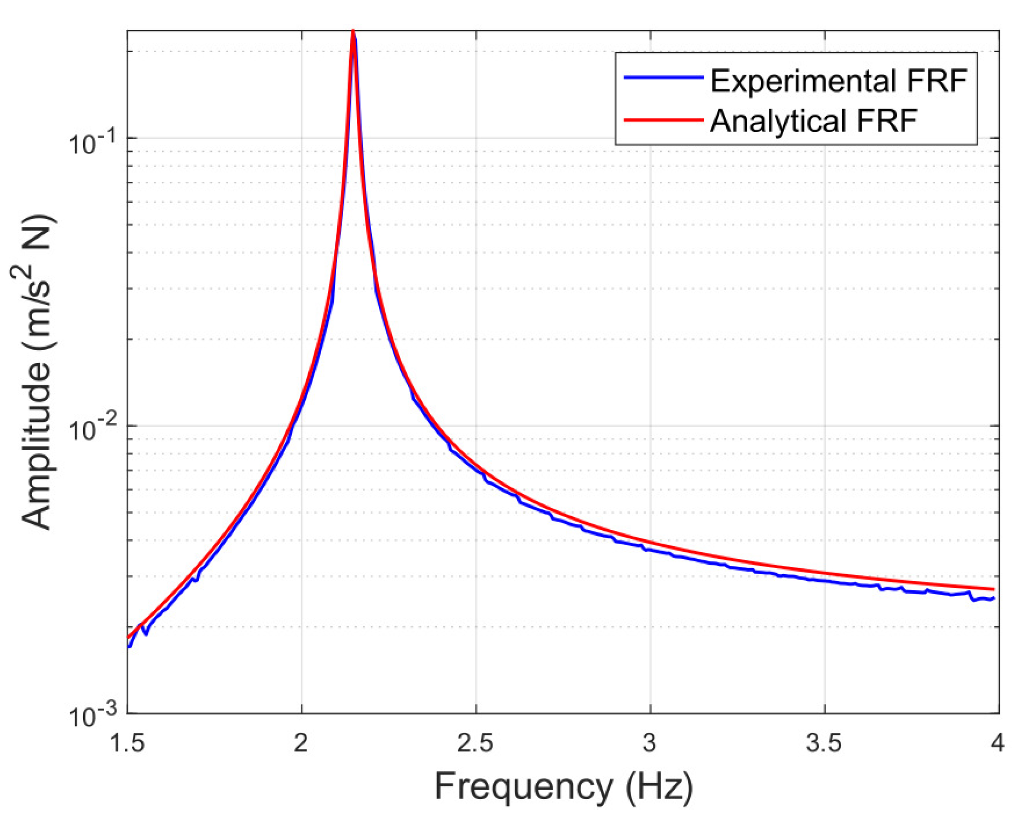
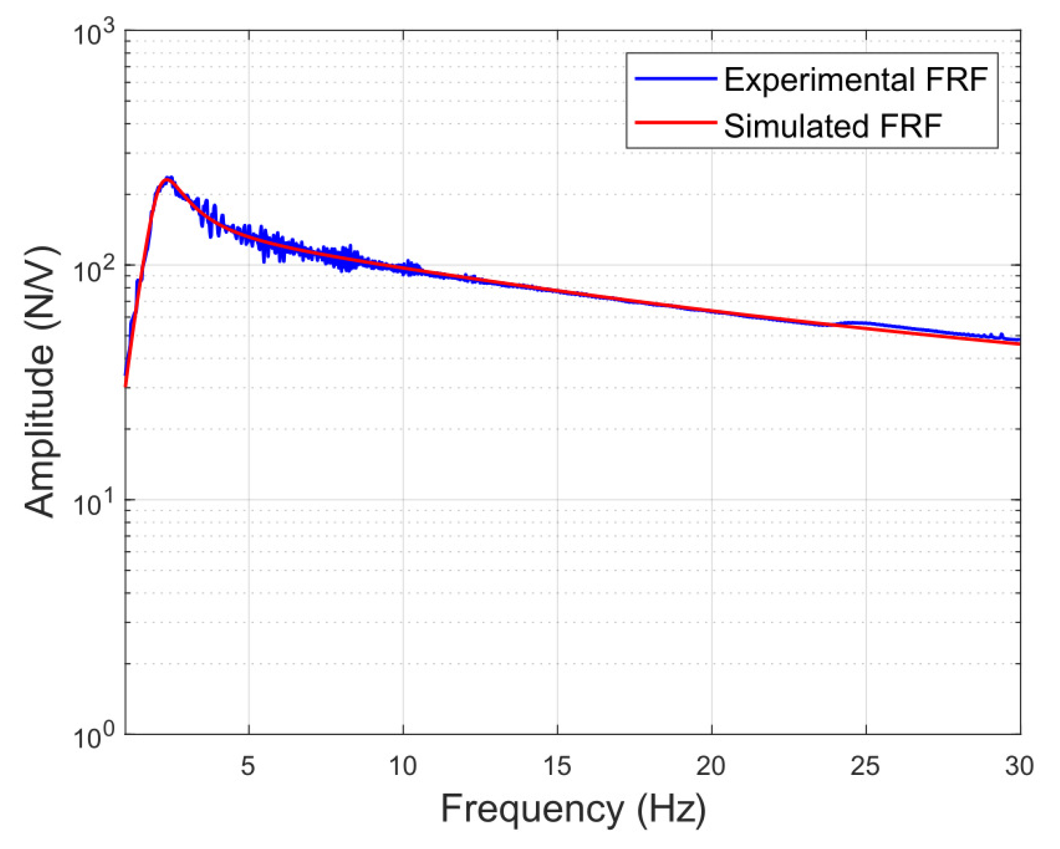
The modal parameters obtained are expressed in (Equation (7)); in addition, Figure 6 shows the comparison between both experimental and analytical frequency response functions for the first mode of the structure:
ω 0 = 2.147 Hz ξ 0 = 0.406 % m = 520.879 kg

2.3. Actuator and Data Logging System

For developing an AMD system that operates optimally, it is essential to obtain a model that describes the behavior and dynamics of the inertial mass actuator that will be used to feedback forces into the system, allowing to accurately predict how it will behave according to the signal it is fed with.
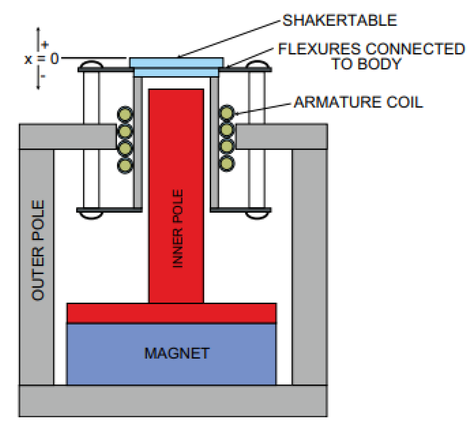
The actuator used consisted of an inertial actuator, the same used to perform the experimental modal analysis presented in Section 2.2.1. The actuator consists of a mobile reaction mass (31.2 kg) attached to a current coil that moves in a magnetic field created by an array of permanent magnets. The moving mass is connected to the frame by a suspension system that can be modeled as a spring stiffness K A and a viscous damping c A (Figure 7). The shaker is powered by means of an amplifier which receives an electrical signal varying between ±5 V and provides the shaker with the necessary power signal in order for the moving mass to oscillate accordingly.
The dynamics of an inertial mass actuator can be described as a third-order transfer function relating the generated force F and the voltage input V, as shown in Equation (8), where K A corresponds to the transducer constant (in N/A), ω A is the natural frequency associated with the suspended moving mass system, ξ A represents the damping coefficient and the pole at ε accounts for the low-pass filtering property of these instruments, absorbing frequencies higher than the cut-off frequency ε (in rad/s) [57]:
G A ( s ) = F ( s ) V ( s ) = K A s 2 s 2 + 2 ξ A ω A s + ω A 2 · 1 s + ε
The process of obtaining the model consisted of optimizing the parameters of the transfer function applying a GA so that the error between the experimental and analytical FRFs is minimum. The experimental FRF is calculated by applying a 60,000-point Blackman window over the experimental data obtained by applying white noise as the input voltage signal V to the shaker in the range of ± 5 V with a test duration of 10 min and a sampling frequency of 1000 Hz. Experimental acceleration was measured with piezoelectric accelerometers (IEPE) from MMF (Metra Mess und Frequenztechnik), so an estimation of the applied force can be computed by multiplying the measured force by the value of the moving mass (31.2 kg). The shaker was identified placed above the ground, significantly more rigid than the structure, in order to avoid interaction effects. The GA-employed parameters are detailed in Table 2.
Equation (9) displays the obtained transfer function, where the values determined for each parameter are K A = 9348.52 N/V, ω A = 13.69 rad/s (2.18 Hz), ξ A = 0.26 and ε = 78.23 rad/s (12.45 Hz). Figure 8 shows a comparison between the experimental and the fit FRF.
G A ( s ) = 9348.52 s 2 s 3 + 85.44 s 2 + 751.8 s + 14 , 660

3. Active Control Strategy and Methodology

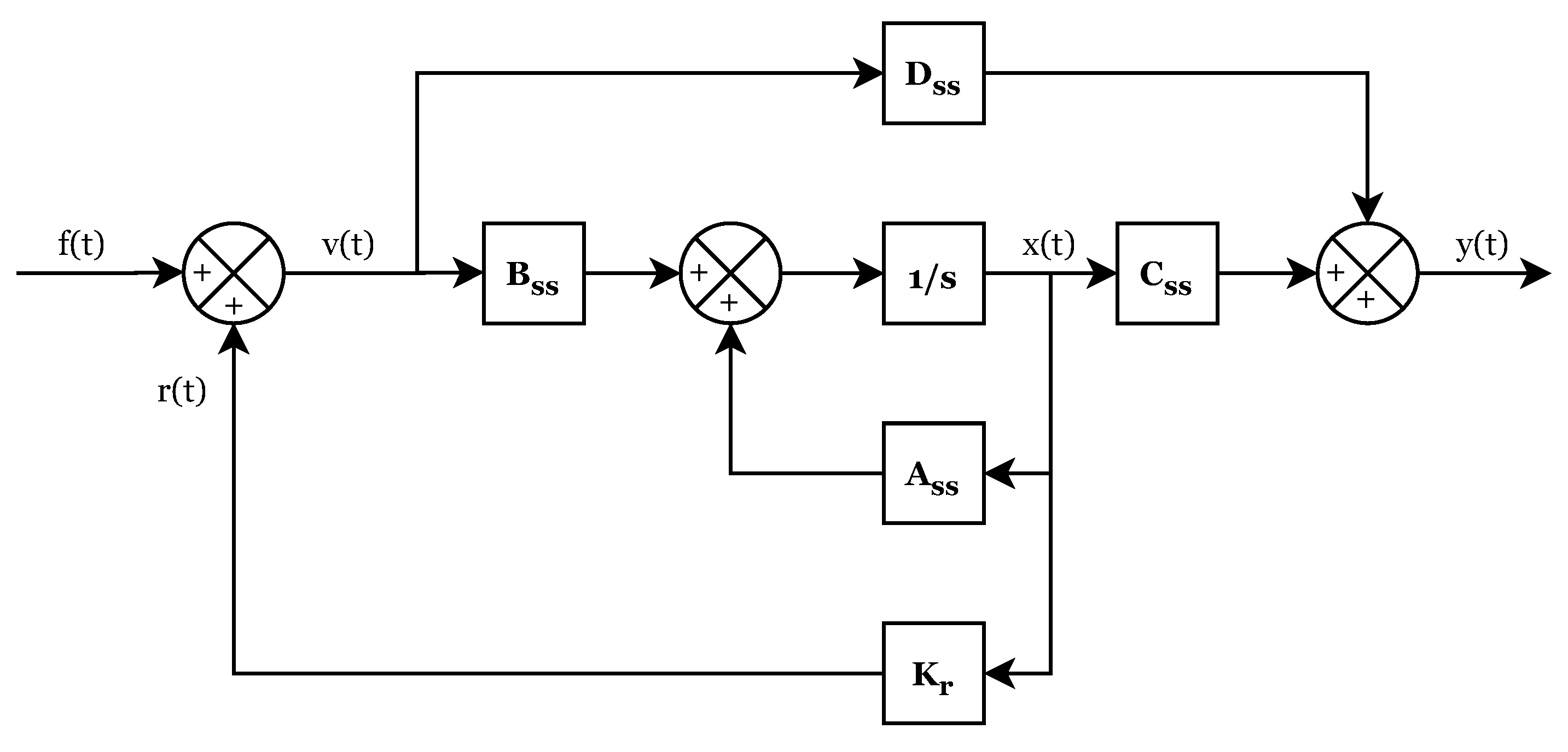
The architecture of the control algorithm implemented in this paper is further detailed in this section. A state feedback control structure is used, whose basic operation scheme is shown in Figure 9. This control structure consists of multiplying the state variable vector by the feedback gain, obtaining the signal in volts to be applied on the actuator. In the proposed approach, the design of the control law consists of selecting the feedback gain K r so that the closed-loop system performs as efficiently as possible, performing this step by applying a heuristic optimization algorithm to optimize this behavior.
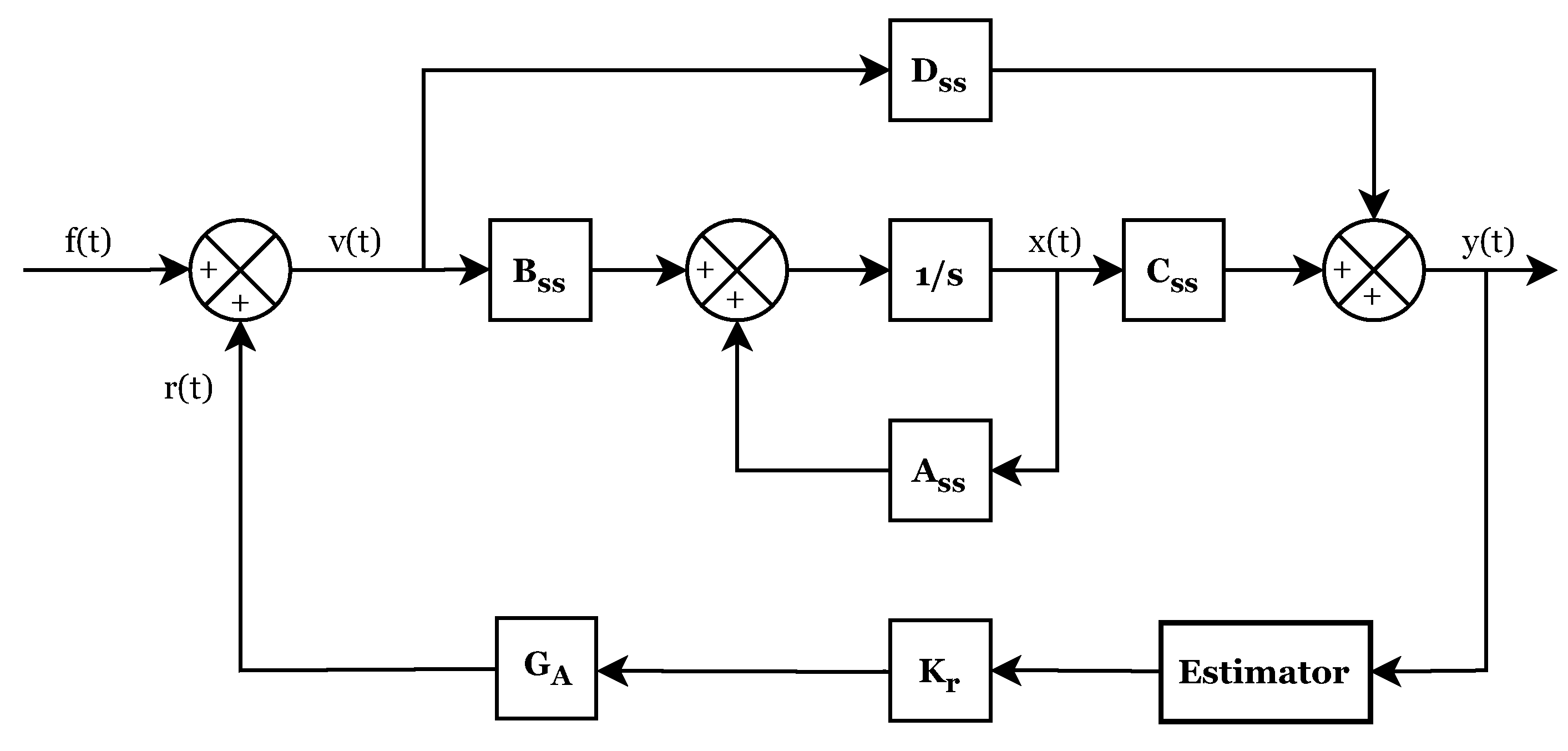
Nevertheless, in the experimental system, no devices are available to measure the position and velocity of the structure (state variables), since only accelerometers are available. Therefore, it is necessary to implement a state estimator, as shown in Figure 10.

3.1. State Estimator

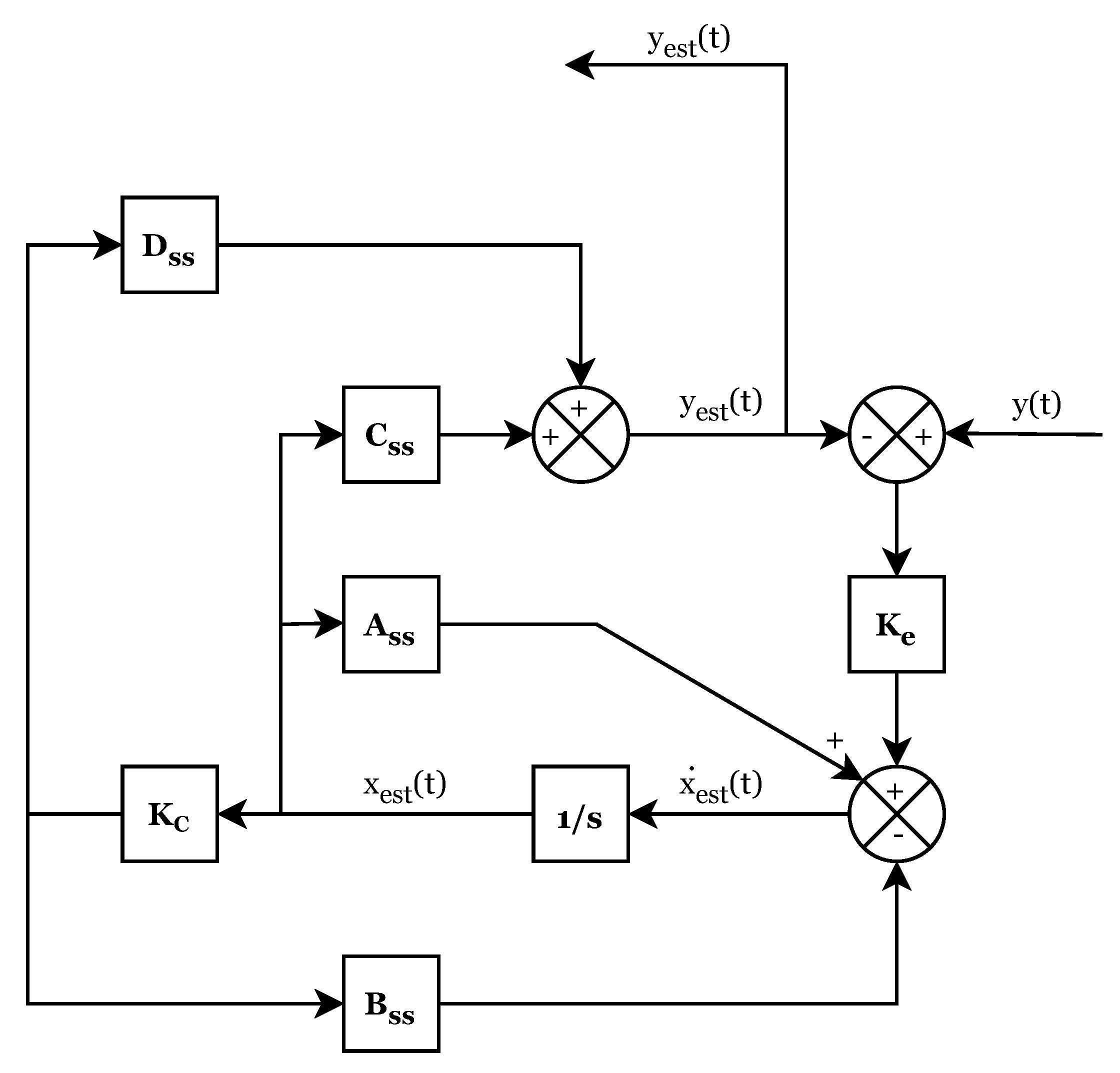
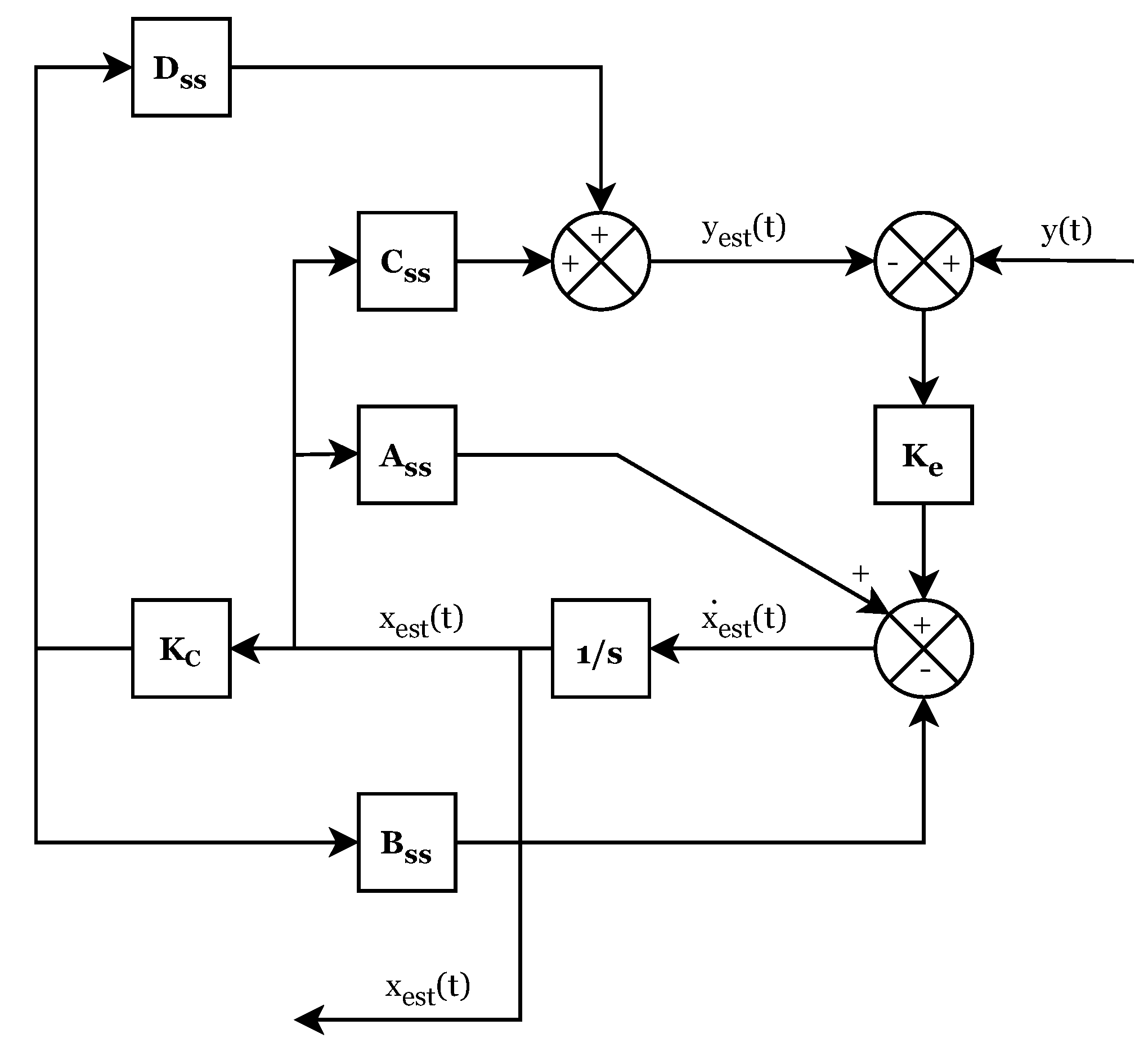
For designing the state estimator, the block diagram shown in Figure 11 was considered, where matrices A s s , B s s , C s s and D s s represents the state space matrices of the open-loop system (Equation (5)), x e s t represent the estimation of the space state variables (position and velocity), y e s t is the estimate acceleration and K e and K c are constant matrices of dimensions [ n s s × p s s ] and [ m s s × n s s ], respectively, where n s s represents the number of state variables of the open-loop system, m s s the number of inputs and p s s the number of outputs. In this case, K e is a (2 × 1) matrix that multiplies the error signal between the measured and estimated acceleration and K c is a (1 × 2) matrix that multiplies the estimated state variables, converting them to force units.
In the estimator design phase, the goal is to determine the values of K e and K c so that, in the implementation phase, the estimator is able work as desired. For this purpose, the estimator can be represented as a state space system, where the input is the measured acceleration (y), the output is the estimated acceleration ( y e s t ), and the state variables are ( x e s t ). According to the block diagram shown in Figure 11, the state equation for this system may be expressed as in Equation (10). Furthermore, the coefficients of the space state matrices of the system, which are denoted as A e s t , B e s t , C e s t and D e s t , and the output equation are shown in Equations (11) and (12), respectively:
x ˙ e s t = A s s x e s t B s s K c x e s t K e C s s x e s t K e D s s K c x e s t + K e y ( t ) x ˙ e s t = ( A s s B s s K c K e C s s K e D s s K c ) x e s t + K e y ( t )
A e s t = ( A s s B s s K c K e C s s K e D s s K c ) B e s t = K e C e s t = A e s t ( 2 , : ) D e s t = 0
y e s t = x ¨ e s t = C e s t x e s t + D e s t y ( t )
Then, the GA optimization algorithm was applied minimizing the error between the measured acceleration (system input) and the estimated acceleration (system output). For this, K e and K c were optimized so that the FRF of the system was as close as possible to a line of constant unit value in the frequency range corresponding to the first mode of the structure (1.5–4 Hz), meaning that the output value is as similar as possible to the input value. The parameters of the GA for the optimization of the estimator gains are shown in Table 3.
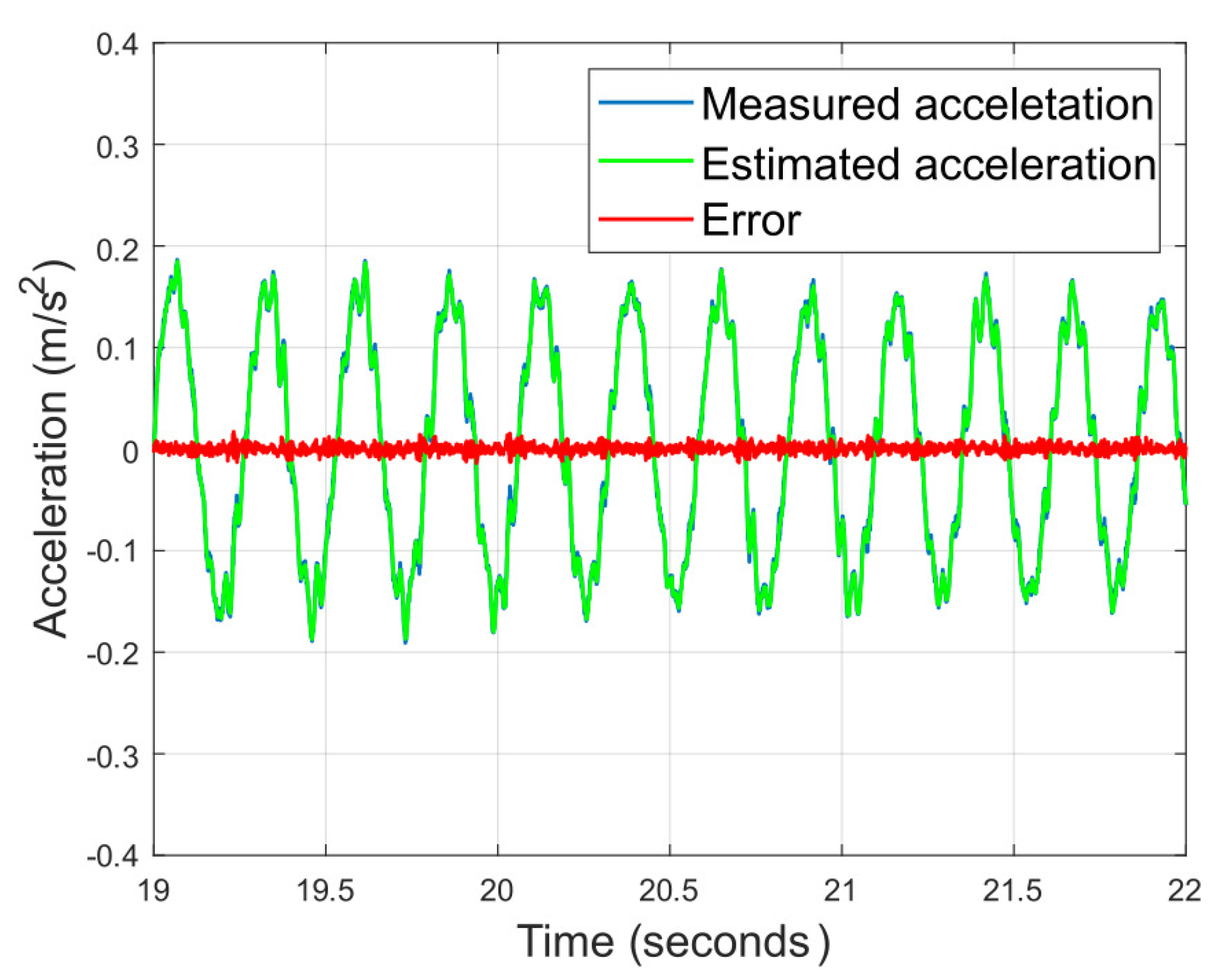
The optimized values obtained are represented in Equation (13). Figure 12 shows the frequency response function of the estimator space state system and Figure 13 shows the validation of the estimator in the time domain, confirming that the error between measured and estimated acceleration is minimal.
K c = 0.0001 10.7464 K e = 8.8555 0.0001
Once the estimator has been designed and the values of the matrices K e and K c have been determined, the implementation procedure consisted of changing the system output to be the estimated state variables of the structure (Figure 14) rather than the estimated acceleration, modifying the system output equation in the state space representation of the estimator, and thus, changing the matrices C e s t and D e s t (Equations (14) and (15)):
C e s t = 1 0 0 1 D e s t = 0
x e s t = C e s t x e s t + D e s t y ( t ) x e s t x ˙ e s t = 1 0 0 1 x e s t x ˙ e s t

3.2. Control Law Design

The controller feedback gain has been designed using evolutionary computation, so that the criteria defined in Table 4 are used as the fitness function, including the additional requirement that the closed loop system poles must be located in the negative semi-plane of the real axis, in order to ensure the stability of the whole system. The remaining parameters of the GA are detailed in Table 5.
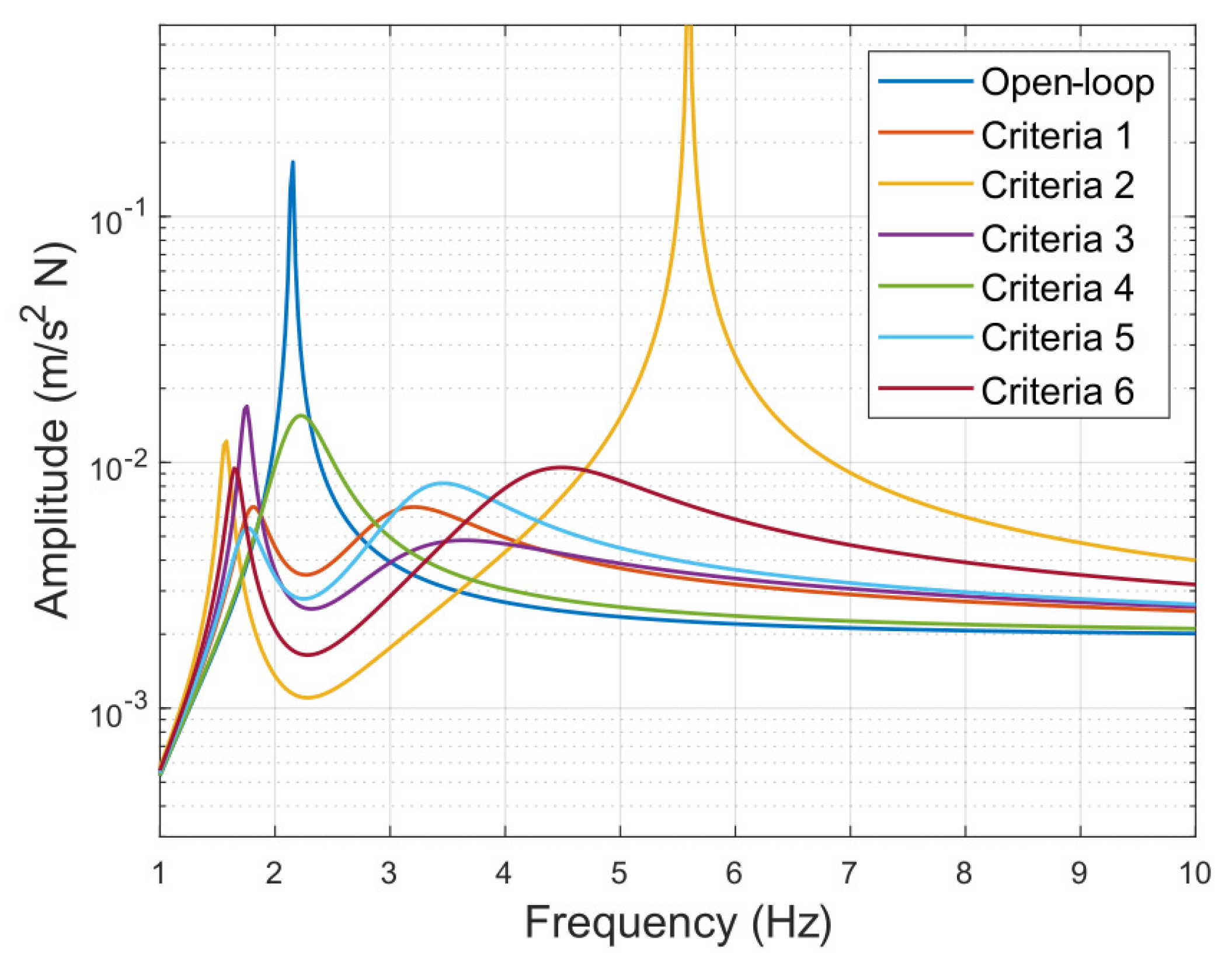
The values for the gain obtained after executing the optimization algorithm are shown in Equation (16). Subsequently, the closed-loop performance of the system was tested for the different calculated values. Figure 15 shows the FRFs obtained for these systems. The appearance of two peaks instead of one may be observed, which can be explained by the coupling between the dynamics of the first mode of the structure with the one associated with the shaker, since both systems exhibit very close natural frequencies (2.15 vs. 2.17 Hz). The performance of these systems has also been evaluated for a step input of amplitude 1 N. The settling time of each criteria, defined as the time before the system reaches a stationary error of less than 2%, are shown in Table 6, where the maximum value of the closed-loop FRFs as well as its value at the resonance frequency of the structure for the different criteria are displayed.
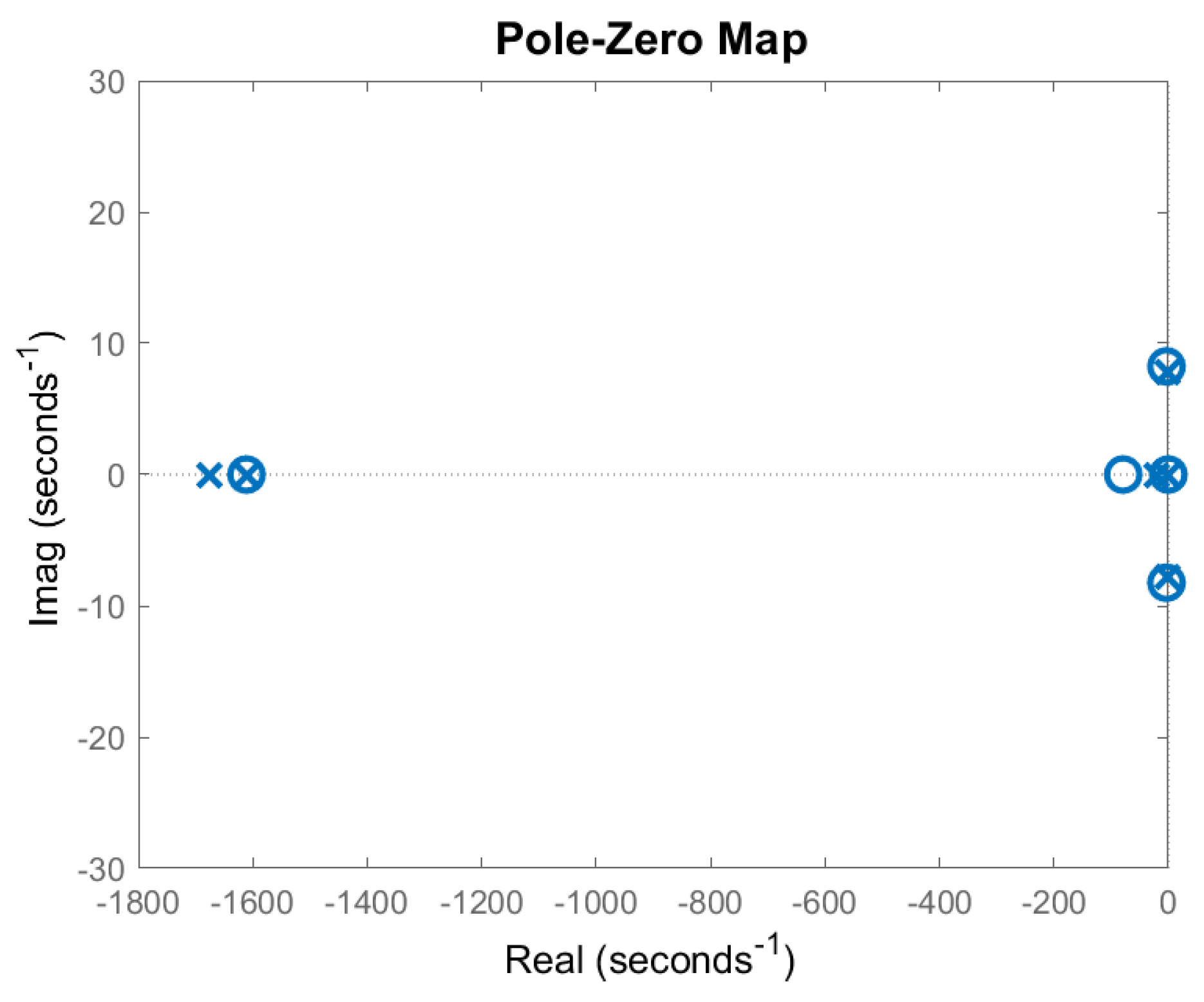
Finally, the gain obtained by criterion 5 was the one selected to be implemented, since it presents a fairly fast settling time, besides a stable behavior in the whole frequency range. In order to verify the stability of the control system, the poles and zeros of the closed-loop system are represented graphically, verifying that its real part is located in the negative half-plane. Figure 16 shows the location of the poles and zeros of the closed-loop system (order 9), showing that indeed, there is no root in the positive half-plane.
K 1 = 213.14 5.02 K 2 = 634.41 25.12 K 3 = 227.10 14.40 K 4 = 52.44 0.77 K 5 = 277.91 4.57 K 6 = 421.05 16.75

4. System Deployment and Validation

This section describes both the implementation of the developed control system in the low-cost controller (Section 4.1) and its experimental validation to assess the efficacy of its performance (Section 4.2).

4.1. System Deployment in the Low-Cost Controller

For the implementation of the system in the myRIO 1900 low-cost controller, a transfer function was used to generate the voltage signal sent to the actuator according to the acceleration measurement provided by a MEMS digital accelerometer (ADXL355). This transfer function (Equation (17)) was calculated as the product of the feedback gain and the state estimator, and was then discretized (Equation (18)) using a first-order hold method with a sampling time of 0.001 s.
The system was deployed in the controller using Labview 2019 software. In addition, a low-pass filter was included in order to avoid instabilities due to the dynamics of the structure associated with high frequencies, since the control system does not take into account these dynamics when modeling only its first mode. A point-by-point finite impulse response filter was used, applying a Welsch window with a cut-off frequency of 24 Hz and 50 taps:
T F ( s ) = 2461 s 3 + 3.947 · 10 6 s 2 1.074 · 10 7 s 1.75 · 10 6 s 4 + 3222 s 3 + 2.596 · 10 6 s 2 + 8.005 · 10 5 s + 6.171 · 10 4
T F ( z ) = 0.7679 z 4 1.238 z 3 + 0.07964 z 2 + 0.4815 z 0.09068 z 4 + 2.399 z 3 + 1.838 z 2 0.479 z + 0.03986

4.2. Experimental Validation

The performance of the active control system developed is assessed in this section. For this purpose, the behavior of the open and closed loop systems was compared both in the frequency domain, calculating their respective FRF, and in the time domain, measuring the time taken for both systems to return to the initial stationary position starting from the same initial conditions. Finally, both systems were tested in loaded conditions, carrying out walking tests on the structure close to its resonance frequency.

4.2.1. Frequency Domain Validation

The FRFs of both the open and closed loop systems were experimentally obtained via impact, measuring the induced force with a Mutronic load cell with a capacity of up to 500 kg and a sensitivity of 2 mV/V.
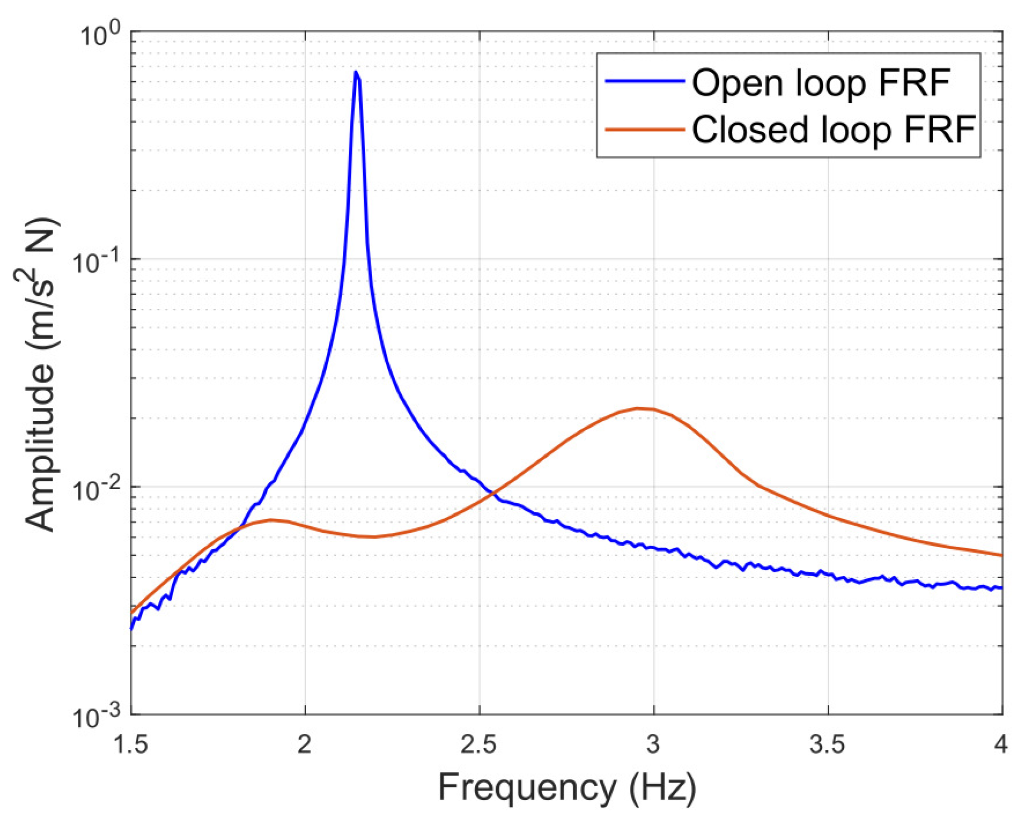
Figure 17 and Figure 18 shows the comparison of open-loop and closed-loop systems, both in the whole frequency domain and in the frequency range around the first natural frequency of the structure, for which the control system was designed. It may be appreciated in these figures that at the structure’s natural frequency, the system response is reduced from 0.662 to 0.006055 m/s 2 N when applying the control system, representing a decrease of 99.09%. Furthermore, the maximum value of the controlled system presents an amplitude of 0.02207 m/s 2 N at a frequency of 2.95 Hz, which also represents a reduction of 96.67% with respect to the maximum value of the uncontrolled system.

4.2.2. Time Domain Validation

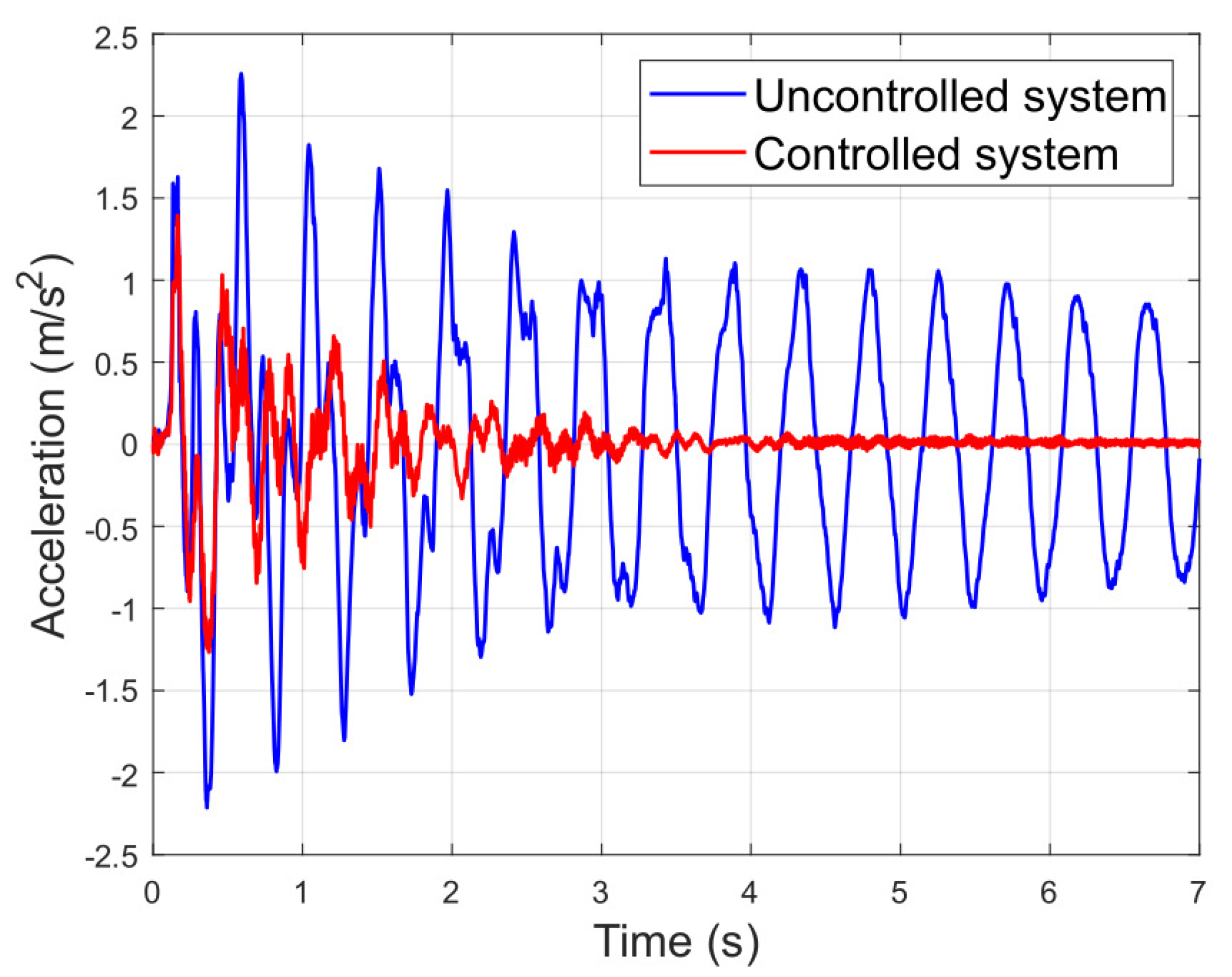
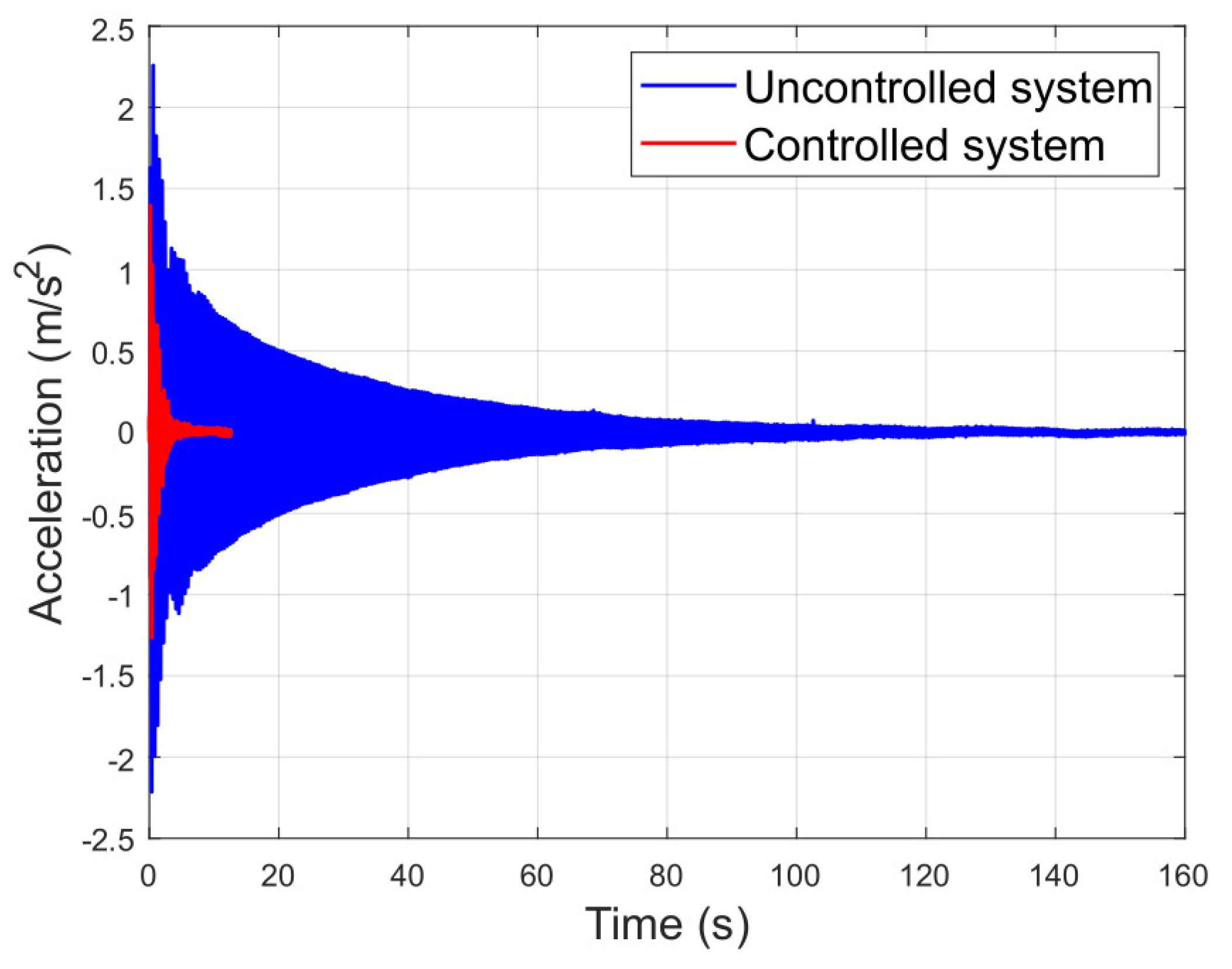
The performance of the feedback system in the time domain is also studied by comparing it with the uncontrolled system. The response of the systems to a step input is analyzed, setting the same initial conditions to compare the time taken for the two systems to return to rest position. For this purpose, the maximum displacement of the platform at its midpoint was limited, so that when a person jumps off the structure, the system starts from a position of constant displacement and zero velocity, making the experiment repeatable for both systems.
Figure 19 and Figure 20 shows the results of this experiment, where it is observed that the initial excitation of both systems is roughly the same. However, the controlled system stops significantly earlier than the uncontrolled system. More specifically, the uncontrolled system takes 121.4 s to reach an acceleration of less than 2% of the initial impulse, while the controlled system takes 4.2 s, which means a reduction of 96.54%.

4.2.3. In-Transit Validation

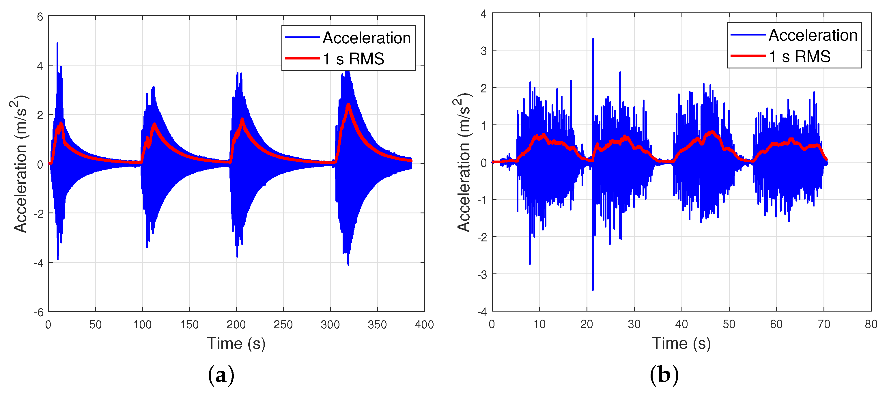
Finally, a walking test was carried out to assess the efficiency of the designed control device. It consisted of walking from one extreme to the other of the footbridge at 2.15 Hz, matching its first vibration mode. The pacing frequency was controlled using a metronome set to 129 beats per minute (bpm). The test was repeated four times, waiting until the platform had completely stopped before every transit. All the tests were carried out by a person of approximately 700 N. The results are compared by means of the maximum peak acceleration and the maximum transient vibration value (MTVV) computed from the 1-s running root mean square (RMS) acceleration [58], and they are displayed in Figure 21a,b for the uncontrolled and controlled systems, respectively. A reduction of 66.07% (from 2.412 to 0.8183 m/s 2 ) when applying the control system may be observed.

5. Discussion and Conclusions

Throughout this paper, the mitigation of human-induced vibrations on a lab-scale footbridge using an active control system has been addressed. Once the dynamic properties of both the structure and the actuator were identified after performing an experimental modal analysis, the design and implementation of an active control system were carried out based on a state feedback strategy. The design of a state estimator was also necessary. Evolutionary computation by means of GA was used throughout the whole article in order to fit the different models and obtain the optimum gains of the control architectures according to different criteria.
This work has focused on the mitigation of vibrations at low frequencies, which are those that can potentially be excited by humans. Therefore, the control strategy has been designed accounting for a range of frequencies below 5 Hz. Since only the first bending mode of the structure fell within this range, a reduction was made for considering the structure as a single-degree-of-freedom system. The performance of the presented AMD for mitigate the vibrations associated with this first mode is experimentally validated, achieving an impressive 99.09% reduction in the amplitude response at the first resonant frequency, as well as a 66.07% MTVV reduction when walking at this frequency. The efficiency of the system has also been validated by evaluating the settling time for a step input, obtaining a 96.54% reduction with respect to the uncontrolled system.
As a consequence of just modeling the structure performance in a frequency range around its first mode, it has been necessary to implement a low-pass filter in the controller in order to avoid instabilities due to the dynamics associated with the high frequencies that are beyond the designed model. This filter limits the controller’s processing time, which affects the cycle time chosen in the system. Lowering this cycle time (currently, it is fixed to 1 ms) will make the system act faster, resulting in better performance. Future work in this direction will be to model the structure as a multi-degree-of-freedom system, in order to remove the signal filter, as well as to make the control system able to mitigate several modes simultaneously.
Furthermore, this work has focused on using low-cost means, employing a NI myRIO 1900 controller, whose cost is 83% lower than other traditional systems of the same brand, such as the Compact RiO-9030 (608 EUR vs. 3677 EUR). The accelerometers used (MEMS ADXL355BEZ) also represent an important saving of 87% with respect to piezoelectric accelerometers KS76C10 (44 EUR vs. 360 EUR). However, the exciter used is a high-cost commercial device (around 25,000 EUR), so that another future line of work is the development of a low-cost inertial mass exciter.
Future lines of work will focus on the use of a multiple-degrees-of-freedom model. This would slightly complicate the modal analysis and platform modeling phase; however, it would allow knowing the expected behavior of more points of the structure, instead of only its midpoint, so that the control laws could be established knowing how the feedback will affect the overall structure, and eliminating instabilities due to platform torsion or high frequencies, as they would now be contemplated in the control system, so that the low-pass filter could be eliminated with the consequent reduction in data processing time for the system output. In addition, the influence of the actuator position will be analyzed, aiming at minimizing the response of the structure, thus converting the problem into an MISO scheme.
Author Contributions

Conceptualization, C.P.-R., J.P.-A., A.M., and Á.I.-P.; methodology, C.P.-R., A.M., and Á.I.-P.; software, C.P.-R., and J.P.-A.; validation, C.P.-R., A.M., and Á.I.-P.; investigation, C.P.-R., J.P.-A., A.M., and Á.I.-P.; resources, J.P.-A.; writing—original draft preparation, C.P.-R., J.P.-A., A.M., and Á.I.-P.; supervision, A.M., and J.P.-A.; project administration, J.P.-A.; funding acquisition, J.P.-A., and A.M. All authors have read and agreed to the published version of the manuscript.

Funding

This research was funded by the project PID2020-115454GB-C21 of the Spanish Ministry of Science and Innovation.

Data Availability Statement

Data will be available on request.

Conflicts of Interest

The authors declare no conflict of interest.

References

  1. Szafran, J.; Zingoni, A.; Repetto, M.P.; Kamiński, M. Lightweight structures in civil engineering–contemporary problems. Bull. Pol. Acad. Sci. Tech. Sci. 2023, 71, e144589. [Google Scholar]
  2. Hanagan, L.M.; Raebel, C.H.; Trethewey, M.W. Dynamic measurements of in-place steel floors to assess vibration performance. J. Perform. Constr. Facil. 2003, 17, 126–135. [Google Scholar] [CrossRef]
  3. Setareh, M. Vibration serviceability issues of slender footbridges. J. Bridge Eng. 2016, 21, 04016084. [Google Scholar] [CrossRef] [Green Version]
  4. Bachmann, H. Case studies of structures with man-induced vibrations. J. Struct. Eng. 1992, 118, 631–647. [Google Scholar] [CrossRef]
  5. Saaed, T.E.; Nikolakopoulos, G.; Jonasson, J.E.; Hedlund, H. A state-of-the-art review of structural control systems. J. Vib. Control. 2015, 21, 919–937. [Google Scholar] [CrossRef]
  6. Lievens, K.; Lombaert, G.; De Roeck, G.; Van den Broeck, P. Robust design of a TMD for the vibration serviceability of a footbridge. Eng. Struct. 2016, 123, 408–418. [Google Scholar] [CrossRef]
  7. Van Nimmen, K.; Verbeke, P.; Lombaert, G.; De Roeck, G.; Van den Broeck, P. Numerical and experimental evaluation of the dynamic performance of a footbridge with tuned mass dampers. J. Bridge Eng. 2016, 21, C4016001. [Google Scholar] [CrossRef]
  8. Li, Q.; Fan, J.; Nie, J.; Li, Q.; Chen, Y. Crowd-induced random vibration of footbridge and vibration control using multiple tuned mass dampers. J. Sound Vib. 2010, 329, 4068–4092. [Google Scholar] [CrossRef]
  9. Wang, D.; Wu, C.; Zhang, Y.; Li, S. Study on vertical vibration control of long-span steel footbridge with tuned mass dampers under pedestrian excitation. J. Constr. Steel Res. 2019, 154, 84–98. [Google Scholar] [CrossRef]
  10. Preumont, A.; Seto, K. Active Control of Structures; John Wiley & Sons: New York, NY, USA, 2008. [Google Scholar]
  11. Casado, C.M.; Díaz, I.M.; de Sebastián, J.; Poncela, A.V.; Lorenzana, A. Implementation of passive and active vibration control on an in-service footbridge. Struct. Control. Health Monit. 2013, 20, 70–87. [Google Scholar] [CrossRef]
  12. Fisco, N.; Adeli, H. Smart structures: Part I—Active and semi-active control. Sci. Iran. 2011, 18, 275–284. [Google Scholar] [CrossRef] [Green Version]
  13. Datta, T. A state-of-the-art review on active control of structures. Iset J. Earthq. Technol. 2003, 40, 1–17. [Google Scholar]
  14. Arvanitis, K.; Zacharenakis, E.; Soldatos, A.; Stavroulakis, G. New trends in optimal structural control. Sel. Top. Structron. Mechatron. Syst. 2003, 3, 321. [Google Scholar]
  15. Casciati, S.; Chen, Z. An active mass damper system for structural control using real-time wireless sensors. Struct. Control Health Monit. 2012, 19, 758–767. [Google Scholar] [CrossRef]
  16. Díaz, I.M.; Reynolds, P. Robust saturated control of human-induced floor vibrations via a proof-mass actuator. Smart Mater. Struct. 2009, 18, 125024. [Google Scholar] [CrossRef] [Green Version]
  17. Díaz, I.M.; Reynolds, P. Acceleration feedback control of human-induced floor vibrations. Eng. Struct. 2010, 32, 163–173. [Google Scholar] [CrossRef] [Green Version]
  18. Wang, X.; Pereira, E.; García-Palacios, J.H.; Díaz, I.M. A general vibration control methodology for human-induced vibrations. Struct. Control. Health Monit. 2019, 26, e2406. [Google Scholar] [CrossRef]
  19. Talib, E.; Shin, J.H.; Kwak, M.K. Designing multi-input multi-output modal-space negative acceleration feedback control for vibration suppression of structures using active mass dampers. J. Sound Vib. 2019, 439, 77–98. [Google Scholar] [CrossRef]
  20. Zhang, Y.; Ma, G.; Wu, G.; Li, L. Modeling and nonlinear optimal control of active mass damper with rotating actuator for structural vibration control. Struct. Control Health Monit. 2022, 29, e2871. [Google Scholar] [CrossRef]
  21. Chen, C.J.; Li, Z.H.; Teng, J.; Wu, Q.G.; Lin, B.C. A variable gain state-feedback technique for an AMD control system with stroke limit and its application to a high-rise building. Struct. Des. Tall Spec. Build. 2021, 30, e1816. [Google Scholar] [CrossRef]
  22. Stavroulakis, G.; Marinova, D.; Hadjigeorgiou, E.; Foutsitzi, G.; Baniotopoulos, C. Robust active control against wind-induced structural vibrations. J. Wind. Eng. Ind. Aerodyn. 2006, 94, 895–907. [Google Scholar] [CrossRef]
  23. Pourzeynali, S.; Lavasani, H.; Modarayi, A. Active control of high rise building structures using fuzzy logic and genetic algorithms. Eng. Struct. 2007, 29, 346–357. [Google Scholar] [CrossRef]
  24. Miyamoto, K.; She, J.; Sato, D.; Yasuo, N. Automatic determination of LQR weighting matrices for active structural control. Eng. Struct. 2018, 174, 308–321. [Google Scholar] [CrossRef]
  25. Etedali, S.; Tavakoli, S. PD/PID controller design for seismic control of high-rise buildings using multi-objective optimization: A comparative study with LQR controller. J. Earthq. Tsunami 2017, 11, 1750009. [Google Scholar] [CrossRef]
  26. Chu, S.Y.; Yeh, S.W.; Lu, L.Y.; Peng, C.H. Experimental verification of leverage-type stiffness-controllable tuned mass damper using direct output feedback LQR control with time-delay compensation. Earthq. Struct. 2017, 12, 425–436. [Google Scholar] [CrossRef]
  27. Shi, Y.; Becker, T.C.; Furukawa, S.; Sato, E.; Nakashima, M. LQR control with frequency-dependent scheduled gain for a semi-active floor isolation system. Earthq. Eng. Struct. Dyn. 2014, 43, 1265–1284. [Google Scholar] [CrossRef]
  28. Fallah, N.; Ebrahimnejad, M. Active control of building structures using piezoelectric actuators. Appl. Soft Comput. 2013, 13, 449–461. [Google Scholar] [CrossRef]
  29. Xu, Z.D.; Huang, X.H.; Xu, F.H.; Yuan, J. Parameters optimization of vibration isolation and mitigation system for precision platforms using non-dominated sorting genetic algorithm. Mech. Syst. Signal Process. 2019, 128, 191–201. [Google Scholar] [CrossRef]
  30. Katebi, J.; Shoaei-parchin, M.; Shariati, M.; Trung, N.T.; Khorami, M. Developed comparative analysis of metaheuristic optimization algorithms for optimal active control of structures. Eng. Comput. 2020, 36, 1539–1558. [Google Scholar] [CrossRef]
  31. Islam, B.; Ahsan, R. Optimization of tuned mass damper parameters using evolutionary operation algorithm. In Proceedings of the 15th World Conference in Earthquake Engineering, Lisbon, Portugal, 24–28 September 2012. [Google Scholar]
  32. Ulusoy, S.; Nigdeli, S.M.; Bekdaş, G. Novel metaheuristic-based tuning of PID controllers for seismic structures and verification of robustness. J. Build. Eng. 2021, 33, 101647. [Google Scholar] [CrossRef]
  33. Ulusoy, S.; Bekdaş, G.; Nigdeli, S.M. Active structural control via metaheuristic algorithms considering soil-structure interaction. Struct. Eng. Mech. Int. J. 2020, 75, 175–191. [Google Scholar]
  34. Karanki, S.B.; Mishra, M.K.; Kumar, B.K. Particle swarm optimization-based feedback controller for unified power-quality conditioner. IEEE Trans. Power Deliv. 2010, 25, 2814–2824. [Google Scholar] [CrossRef]
  35. Manna, S.; Mani, G.; Ghildiyal, S.; Stonier, A.A.; Peter, G.; Ganji, V.; Murugesan, S. Ant colony optimization tuned closed-loop optimal control intended for vehicle active suspension system. IEEE Access 2022, 10, 53735–53745. [Google Scholar] [CrossRef]
  36. Dai, T.; Sznaier, M. A convex optimization approach to synthesizing state feedback data-driven controllers for switched linear systems. Automatica 2022, 139, 110190. [Google Scholar] [CrossRef]
  37. Sun, X.; Hu, C.; Lei, G.; Guo, Y.; Zhu, J. State feedback control for a PM hub motor based on gray wolf optimization algorithm. IEEE Trans. Power Electron. 2019, 35, 1136–1146. [Google Scholar] [CrossRef]
  38. Katoch, S.; Chauhan, S.S.; Kumar, V. A review on genetic algorithm: Past, present, and future. Multimed. Tools Appl. 2021, 80, 8091–8126. [Google Scholar] [CrossRef]
  39. Lambora, A.; Gupta, K.; Chopra, K. Genetic algorithm-A literature review. In Proceedings of the 2019 International Conference on Machine Learning, Big Data, Cloud and Parallel Computing (COMITCon), Faridabad, India, 14–16 February 2019; IEEE: Piscataway Township, NJ, USA, 2019; pp. 380–384. [Google Scholar]
  40. Ahlawat, A.; Ramaswamy, A. Multiobjective optimal structural vibration control using fuzzy logic control system. J. Struct. Eng. 2001, 127, 1330–1337. [Google Scholar] [CrossRef]
  41. Mei, Z.; Guo, Z.; Chen, L.; Wang, H.; Gao, Y. Genetic algorithm-based integrated optimization of active control systems for civil structures subjected to random seismic excitations. Eng. Optim. 2020, 52, 1700–1719. [Google Scholar] [CrossRef]
  42. Jiang, X.; Adeli, H. Neuro-genetic algorithm for non-linear active control of structures. Int. J. Numer. Methods Eng. 2008, 75, 770–786. [Google Scholar] [CrossRef]
  43. Yamamoto, M.; Aizawa, S.; Higashino, M.; Toyama, K. Practical applications of active mass dampers with hydraulic actuator. Earthq. Eng. Struct. Dyn. 2001, 30, 1697–1717. [Google Scholar] [CrossRef]
  44. Chen, P.C.; Chien, K.Y. Machine-learning based optimal seismic control of structure with active mass damper. Appl. Sci. 2020, 10, 5342. [Google Scholar] [CrossRef]
  45. Goorts, K.; Ashasi-Sorkhabi, A.; Narasimhan, S. Deployable active mass dampers for vibration mitigation in lightweight bridges. J. Struct. Eng. 2017, 143, 04017159. [Google Scholar] [CrossRef]
  46. Sargent, R. Optimal control. J. Comput. Appl. Math. 2000, 124, 361–371. [Google Scholar] [CrossRef] [Green Version]
  47. Zheng, Y.G.; Huang, J.W.; Sun, Y.H.; Sun, J.Q. Building vibration control by active mass damper with delayed acceleration feedback: Multi-objective optimal design and experimental validation. J. Vib. Acoust. 2018, 140, 041002. [Google Scholar] [CrossRef]
  48. Chang, S. Active mass damper for reducing wind and earthquake vibrations of a long-period bridge. Actuators 2020, 9, 66. [Google Scholar] [CrossRef]
  49. Holland, J.H. Adaptation in Natural and Artificial Systems: An Introductory Analysis with Applications to Biology, Control, and Artificial Intelligence; MIT Press: Cambridge, MA, USA, 1992. [Google Scholar]
  50. Lee, J.Y.; Kim, M.S.; Kim, C.T.; Lee, J.J. Study on encoding schemes in compact genetic algorithm for the continuous numerical problems. In Proceedings of the SICE Annual Conference, Takamatsu, Japan, 17–20 September 2007; IEEE: Piscataway Township, NJ, USA, 2007; pp. 2694–2699. [Google Scholar]
  51. Sivanandam, S.; Deepa, S.; Sivanandam, S.; Deepa, S. Genetic Algorithms; Springer: New York, NY, USA, 2008. [Google Scholar]
  52. Pencheva, T.; Atanassov, K.; Shannon, A. Modelling of a stochastic universal sampling selection operator in genetic algorithms using generalized nets. In Proceedings of the Tenth International Workshop on Generalized Nets, Sofia, Bulgaria, 5 December 2009; pp. 1–7. [Google Scholar]
  53. Syswerda, G. Uniform crossover in genetic algorithms. In Proceedings of the ICGA, San Francisco, CA, USA, 1 June 1989; Volume 3, pp. 2–9. [Google Scholar]
  54. Soon, G.K.; Guan, T.T.; On, C.K.; Alfred, R.; Anthony, P. A comparison on the performance of crossover techniques in video game. In Proceedings of the 2013 IEEE International Conference on Control System, Computing and Engineering, Penang, Malaysia, 29 November–1 December 2013; IEEE: Piscataway Township, NJ, USA, 2013; pp. 493–498. [Google Scholar]
  55. Magdaleno, A.; Villacorta, J.J.; Del-Val, L.; Izquierdo, A.; Lorenzana, A. Measurement of Acceleration Response Functions with Scalable Low-Cost Devices. An Application to the Experimental Modal Analysis. Sensors 2021, 21, 6637. [Google Scholar] [CrossRef]
  56. Abhishek, S.; Tiwari, N. Modeling and study of nonlinear effects in electrodynamic shakers. Mech. Syst. Signal Process. 2017, 85, 162–176. [Google Scholar] [CrossRef]
  57. Peláez-Rodríguez, C.; Magdaleno, Á.; Salcedo-Sanz, S.; Lorenzana, A. Human-induced force reconstruction using a non-linear electrodynamic shaker applying an iterative neural network algorithm. Bull. Pol. Acad. Sci. Tech. Sci. 2023, e144615. [Google Scholar]
  58. Vibration, M. Shock—Evaluation of Human Exposure to Whole-Body Vibration—Part 1: General Requirements. International Organization for Standardization; ISO: Geneva, Switzerland, 1997; p. 2631. [Google Scholar]
Figure 1. Floor plans, 3D view and picture of the test structure. (a) Elevation and floor plans of the test structure. Dimensions in mm. (b) 3D view of the footbridge. (c) Picture of the test structure.
Actuators 12 00254 g001
Figure 2. Computational bending modes of the structure obtained with the SAP 2000 model. (a) First bending mode (2.15 Hz); (b) Second bending mode (6.5 Hz); (c) Third bending mode (13.5 Hz).
Actuators 12 00254 g002
Figure 3. Top view of the measurement layout for the experimental tests.
Actuators 12 00254 g003
Figure 4. Experimental setup used for structure identification.
Actuators 12 00254 g004
Figure 5. Accelerance of the structure between 0 and 25 Hz.
Actuators 12 00254 g005
Figure 6. Comparison between simulated and experimental FRF of the system.
Actuators 12 00254 g006
Figure 7. Sketch of the typical electrodynamic inertial actuator [56].
Actuators 12 00254 g007
Figure 8. Transfer function of the actuator G A (s): magnitude in dB referenced to 1 N/V.
Actuators 12 00254 g008
Figure 9. Block diagram of the state feedback control system.
Actuators 12 00254 g009
Figure 10. Block diagram of the state feedback control with the state estimator.
Actuators 12 00254 g010
Figure 11. Block diagram representation of the state space estimator.
Actuators 12 00254 g011
Figure 12. Estimator FRF compared to the target FRF.
Actuators 12 00254 g012
Figure 13. Validation of the estimator on the temporal domain.
Actuators 12 00254 g013
Figure 14. Block diagram representation of the state space estimator.
Actuators 12 00254 g014
Figure 15. Closed-loop FRF for different feedback gain values.
Actuators 12 00254 g015
Figure 16. Closed-loop system pole-zero map.
Actuators 12 00254 g016
Figure 17. Uncontrolled and controlled system frequency response functions between 0 and 30 Hz.
Actuators 12 00254 g017
Figure 18. Uncontrolled and controlled system frequency response functions between 1.5 and 4 Hz.
Actuators 12 00254 g018
Figure 19. Time response to a step input.
Actuators 12 00254 g019
Figure 20. Time response to a step input.
Actuators 12 00254 g020
Figure 21. Walking response at 2.15 Hz of the controlled system. (a) Uncontrolled system (MTVV = 2.412 m / s 2 ); (a) Controlled system (MTVV = 0.8183 m / s 2 ).
Actuators 12 00254 g021
Table 1. Mechanical properties of GLULAM 24 h.
Mean elasticity modulus (parallel)12,500 N/mm 2
Mean elasticity modulus (perpendicular)300 N/mm 2
Shear modulus650 N/mm 2
Bending strength24 N/mm 2
Tensile strength (parallel)19.2 N/mm 2
Tensile strength (perpendicular)0.5 N/mm 2
Compression strength (parallel)24 N/mm 2
Compression strength (perpendicular)2.5 N/mm 2
Characteristic density420 kg/m 3
Table 2. GA-employed parameters for the modeling of the actuator dynamics.
Number of variables:4 ( K A , ξ A , ω A , ε )
Maximum number of iterations:100
Population Size:500
Upper limits of each variable ( K A , ξ A , ω A , ε ):50,000, 1, 20, 200
Lower limits of each variable ( K A , ξ A , ω A , ε ):0, 0, 10, 50
Crossover probability:0.9
Mutation probability:0.1
Fitness function: F G A = 1 n · i = 1 n ( Y ^ i Y i ) 2
Table 3. The parameters of the GA for the optimization of the estimator gains.
Number of variables:4 ( K c 1 , K c 2 , K e 1 y K e 2 )
Maximum number of iterations:100
Population Size:200
Upper limits of each variable ( K c 1 , K c 2 , K e 1 y K e 2 ):100, 100, −0.0001, −0.0001
Lower limits of each variable ( K c 1 , K c 2 , K e 1 y K e 2 ):0.0001, 0.0001, −100, −100
Crossover probability:0.9
Mutation probability:0.1
Fitness function: F G A = 1 n · i = 1 n ( Y ^ i 1 ) 2
Table 4. Fitness function criteria for the optimization of the controller feedback gain.
Fitness Function Criteria
1. Minimization of the maximum value of the FRF of the closed-loop system
2. Minimization of the area below the FRF of the closed-loop system.
3. Minimization of the real part of the closed-loop system pole of higher value.
4. Minimization of the product of the absolute values of the poles of the closed-loop system.
5. Minimization of the time response of the closed-loop system to a chirp input oscillating
between 1.5 and 4 Hz.
6. Balanced combination of criteria 1 and 2.
Table 5. GA parameters for the optimization of the controller feedback gain.
Number of variables:2 ( K r 1 , K r 2 )
Maximum number of iterations:100
Population Size:300
Upper limits of each variable ( K r 1 , K r 2 ):1000, 10
Lower limits of each variable ( K r 1 , K r 2 ):−1000, −10
Crossover probability:0.9
Mutation probability:0.1
Table 6. Evaluated performance for the different closed-loop systems considered.
CriteriaSettling Time [s]Maximum Amplitude [m/s2 N]Amplitude at Structure Resonance [m/s2 N]
Open-loop96.960.170.17
15.020.00660.0035
21144001.610.0011
315.730.0170.0025
44.180.0150.016
54.520.00820.0028
69.640.00940.0016
Disclaimer/Publisher’s Note: The statements, opinions and data contained in all publications are solely those of the individual author(s) and contributor(s) and not of MDPI and/or the editor(s). MDPI and/or the editor(s) disclaim responsibility for any injury to people or property resulting from any ideas, methods, instructions or products referred to in the content.