Abstract
This paper addresses the fault problem in distributed-four-wheel-drive electric vehicle drive systems. First, a fault-factor-based active fault diagnosis strategy is proposed. Second, a fault-tolerant controller is designed to reconstruct motor drive torque based on vehicle stability. This controller ensures that the vehicle maintains stability by providing fault-free motor output torque based on fault diagnosis results. To validate the effectiveness of the fault diagnosis and fault-tolerant control, SIL simulation is conducted using MATLAB/Simulink and CarSim. A hardware-in-the-loop (HIL) simulation platform with the highest confidence level is established based on NI PXI and CarSim RT. Through the HIL simulation experiments, it is shown that the proposed control strategy can accurately diagnose the operating state of the motor, rebuild the motor torque based on stability, and demonstrate robust stability when the drive system fails. Under various fault conditions, the maximum error in the vehicle lateral angular velocity is less than 0.017 rad/s and the maximum deviation in the lateral direction is less than 0.7 m. These findings substantiate the highly robust stability of the proposed method.
1. Introduction
A distributed-drive electric vehicle typically refers to an electric vehicle driven by wheel-side motors or hub motors, offering several advantages over classical centralized single-motor-drive electric vehicles. By eliminating the need for transmission shafts, gearboxes, and other components, the distributed-drive electric vehicle reduces vehicle weight, optimizes the chassis structure, and ensures a more compact design, higher space utilization, and improved transmission efficiency [1]. Moreover, the ability to individually control each driving motor allows for more flexible and precise torque control, enabling the implementation of advanced features such as operational stability, anti-slip driving, and an electronic differential [2,3]. Therefore, it serves as an ideal platform for the application of advanced vehicle dynamics control theories. Furthermore, the redundancy provided by the distributed-drive electric vehicle drive system, with multiple power sources, enables the coordinated control of multiple actuator units to achieve the desired driving torque. This redundancy configuration ensures that even if some of the drive system motors fail, the vehicle can maintain the intended driving state, thus ensuring driving safety [4,5].
However, at the same time, a distributed-drive electric vehicle drive system with multiple actuator redundancy configurations increases the probability of failure. To ensure stable and safe driving, failure control can be employed to take advantage of the redundancy configuration of the drive system actuators. In a distributed-drive electric vehicle, failure control mainly refers to measures such as fault diagnosis, separation, and control of the driving motor in the drive system hardware or software after the occurrence of a failure, but before the vehicle becomes unstable. This reduces the tendency toward instability and improves the safety and reliability of driving [6].
Fault diagnosis provides the theoretical basis for failure control, and precise and reliable identification results are essential for failure control. Reference [7] proposes a fault diagnosis method for distributed-drive electric vehicles based on an online estimator of the tire–road friction coefficient. This method can work well even in the presence of interference and modeling errors and has good robustness. Reference [8] proposes a fault diagnosis method based on actuator redundancy. By comparing the actual motor torque with its nominal value, motor faults can be detected more accurately, and faulty motors can be assessed and located. Reference [9] designs a distributed-drive electric vehicle fault detector based on the Extended Kalman Filter (EKF) wheel hub motor, which can observe hub motor parameter changes caused by faults and identify motor faults. Reference [10] applies differential algebraic methods to diagnose and isolate faults by establishing a motor model. After identifying the faulty motor through fault diagnosis, an effective failure control algorithm needs to be designed to reconstruct torque and fully utilize the advantages of multiple actuator redundancy, ensuring that the vehicle can track the driver’s expected trajectory even if the drive system fails. Reference [11] proposes to compensate for the loss of the faulty motor by using an uncompromised one but lacks consideration of actual working conditions. Reference [12] designs a fault control strategy for distributed-four-wheel drive electric vehicles based on sliding mode control and proposes the use of the motor weight matrix to characterize whether it is working properly. Reference [13] applies fault factor limits to the faulty motor and reconstructs the torque of each wheel motor. Reference [14] proposes a distributed-drive electric vehicle drive failure control method based on power and stability to cope with different failure modes and driving conditions. Reference [15] classifies different failure situations into two categories: the deceleration and stopping type and the maintaining speed type. For the latter, the method suggests shutting down the opposite motor of the faulty motor and using fuzzy control to maintain the expected driving trajectory of the vehicle. References [16,17] propose a hierarchical failure control strategy, which consists of signal acquisition, logic recognition, and failure control layers. Reference [18] designs a torque distribution optimization strategy based on direct lateral force control on top of the conventional drive system failure control to ensure optimal overall performance.
At present, in the event of a failure, the control of the distributed-drive electric vehicle drive system mainly consists of two components: fault diagnosis and failure control. Fault diagnosis primarily involves comparing the actual output torque of the drive motor with the expected output torque or a characteristic value that represents the current output torque, which allows for the determination of whether the motor is malfunctioning. Conversely, failure control mostly employs rule-based methods. Based on the failure mode of the drive system, an appropriate control scheme is employed to reconstruct the driving torque of the remaining functional motors, thereby preserving the vehicle’s power and driving stability.
This paper presents the design of a fault diagnosis tool that uses a cumulative judgment approach, comparing the actual and expected values of the drive motor. By relying on this fault diagnostic method, misjudgment of motor failure caused by motor torque fluctuation can be avoided. Leveraging a set of rules designed to prioritize driving stability, a failure control algorithm is developed for the remaining functional motors to ensure the seamless operation of the vehicle.
2. Drive System Fault Diagnosis and Failure Control Strategy Design
This paper presents a failure control strategy, encompassing fault diagnosis and torque reconstruction, as illustrated in Figure 1. Based on the torque distribution outcomes from lateral stability control, the ratio between the actual motor torque signal collected from the drive system and the expected output motor torque, along with its rate of change, are used as input variables for fuzzy control. The output is the failure factor kl of each drive motor. The current failure mode is identified based on the failure factor kl, which can be categorized into six different modes. The torque reconstruction process follows a set of predefined rules, ensuring optimal driving stability and satisfying the driver’s power requirements to the maximum possible extent, resulting in the final torque input to the drive system, Tis.

Figure 1.
Distributed-Drive Electric Vehicle Drive System Failure Control Framework.
2.1. Active Fault Diagnosis of the Drive System
Based on fuzzy control, a proactive fault diagnosis tool is designed for the drive motor, allowing for timely and accurate monitoring of the motor’s working status, proactively detecting malfunctioning motors, isolating them, and taking failure control measures to ensure safe vehicle operation.
In the proactive fault diagnosis tool for the drive motor, the output failure factor kl has a value of either 0 or 1, with 0 indicating a motor malfunction and 1 indicating normal operation. ρ is defined as:
In the equation, Ti0 represents the expected output torque of the drive motor and Ti1 represents the actual output torque of the drive motor. Both can be obtained by collecting the CAN communication messages of the motor.
A proactive fault diagnosis tool is designed based on fuzzy control, using ρ and its rate of change, ∆ρ, as input variables and σ as the output variable to evaluate the motor’s operating status at this moment. First, the variables are fuzzified, and the fuzzy sets for the input and output variables are defined. The range of ρ is [0, 2], divided into five fuzzy sets. The range of ∆ρ is [−100, 100], divided into three fuzzy sets. The range of the output variable σ is [0.85, 1.05], also divided into three fuzzy sets. The partition of the fuzzy variable fuzzy sets is shown in Table 1. The membership functions of each variable are shown in Figure 2, Figure 3 and Figure 4.

Table 1.
Fuzzy sets of input and output variables for the Fault Diagnosis Fuzzy Controller.
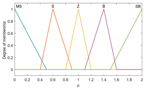
Figure 2.
Membership functions of input variable ρ.
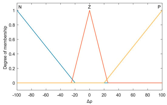
Figure 3.
Membership functions of input variable ∆ρ.
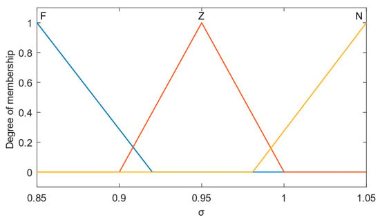
Figure 4.
Membership functions of output variable σ.
Subsequently, based on the fuzzy rules stored in the rule base, fuzzy inference determines the corresponding output variable based on the combination of input variables. The design of fuzzy rules influences the control effectiveness of the fuzzy control and they are established by the continuous fine-tuning of experience and model. The fuzzy inference rules established are shown in Table 2.

Table 2.
Fuzzy inference rules of the Fault Diagnosis Fuzzy Control.
The centroid method is adopted in this article for defuzzification, which ensures a smoother output. As the expected output torque may be zero, leading to a zero point in the denominator of ρ and consequently, an infinite value for ∆ρ, a simple filtering process needs to be applied to the expected output torque before feeding it into the fuzzy controller:
The current motor status is determined based on the output variable σ. If σ ≥ 0.95, the motor is in normal working condition, otherwise, a motor fault is present.
Figure 5 shows a comparison between the expected and actual values of the output torque collected during the on-road test of a distributed-drive vehicle equipped with hub motors on the rear wheels.
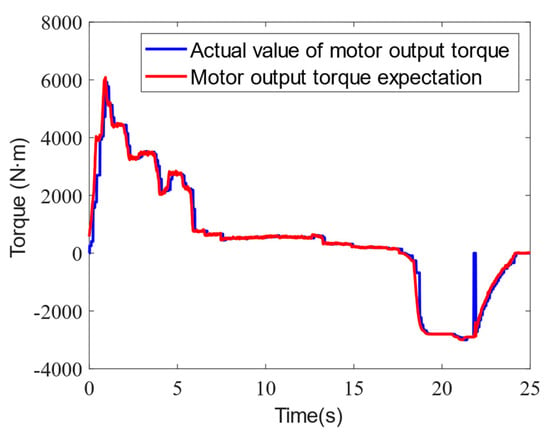
Figure 5.
Comparison of the actual and desired output torque of the hub motor.
It can be observed that the actual and expected values of the output torque of the drive motor are not the same, as small deviations exist under normal circumstances. Fuzzy control can ignore these deviations and accurately determine the working status of the motor. Moreover, at approximately 22 s, the motor experiences torque loss due to communication interference and other factors. This situation is brief, and the motor quickly returns to normal operation. To address this issue, the output results of the fuzzy controller need to be cumulatively analyzed. If the number of fault judgments within a given period exceeds the set threshold, the motor is considered to have failed, and it will be deactivated for isolation treatment. The determination period and threshold can be adjusted according to the real-time requirements of the vehicle.
By tracking the motor’s working status using two global variables and analyzing them with the set threshold, the failure factor kl of the motor can be outputted, and ki = 0 would lead to the locking of the output results to prevent secondary damage to the motor due to frequent failures.
2.2. Drive System Failure Control Strategy
As shown in Figure 6, the failure mode of the drive motor can be divided into six types: no failure, single-motor failure, double-motor failure on different axles and sides, double-motor failure on the same axle, double-motor failure on the same side, and multiple-motor failure. The analysis of the six failure modes is as follows:
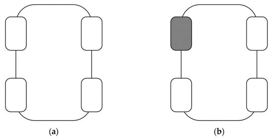
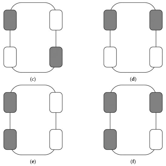
Figure 6.
Drive system failure mode diagram (the grey-colored wheel in the figure represents the wheel driven by the failed motor): (a) Normal operating conditions; (b) Single-motor failure; (c) Dual-motor failure: opposite shaft and opposite side; (d) Dual-motor failure: coaxial; (e) Dual-motor failure: same side; (f) Three-motor failure.
(1) No failure: the vehicle operates normally; (2) Single-motor failure: the lost longitudinal force can be compensated for by reconstructing the torque of the normal working motor, while the lost lateral moment can be compensated for through the driver’s steering angle or reconstructing the torque of the motor; (3) Double-motor failure on different axles and sides: the lost longitudinal driving force and lateral moment can be compensated for by reconstructing the torque of the two non-failed motors, prioritizing stability; (4) Double-motor failure on the same axle: in this case, the drive system is considered as a front- or rear-axle drive format; (5) Double-motor failure on the same side: the lost lateral moment cannot be compensated for, and the vehicle needs to be stopped immediately for treatment; (6) Multiple-motor failure: it is impossible to meet driving requirements, and the vehicle needs to be stopped immediately for treatment.
In addition to normal driving and situations that require immediate braking, this article will propose torque reconstruction control strategies based on vehicle stability for failure modes (2)–(4). For this purpose, a seven-degrees-of-freedom distributed-dive vehicle model shown in Figure 7 is considered, which includes the longitudinal and lateral movement of the vehicle, the yaw motion around the z-axis, and the rotational motion of the four wheels. In the dynamic equation of the model, W is the wheelbase, a is the distance from the front wheel to the center of gravity, b is the distance from the rear wheel to the center of gravity, r is the rolling radius of the wheel, and δ represents the steering angle of the front wheel. ij = fl, fr, rl, rr respectively represent the left front wheel, right front wheel, left rear wheel, and right rear wheel.
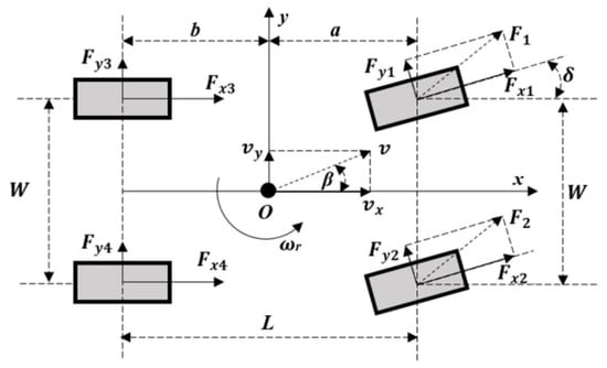
Figure 7.
Distributed-drive electric vehicle 7-degrees-of-freedom model.
When a single-motor failure occurs, taking the example of the failure of the left front wheel motor, the motor output should be isolated and shut off, i.e., Tfls = 0. To improve the real-time performance of the control algorithm, a distribution method that considers the vertical load distribution of the front and rear axles is used, which can make full use of the road attachment rate, at which point the constraint is expressed as follows:
where Td is the total driving torque, ΔM is the additional lateral moment, and kz is the ratio of the sum of the front wheel vertical loads to the sum of the rear wheel vertical loads, which is defined as:
where Fz is the vertical load of the wheel.
Solving Equation (3) yields the drive torque of the three motors that have not failed:
Based on the vehicle’s lateral stability, when the motor output exceeds the maximum torque limit, sacrificing some power is necessary to ensure vehicle stability. The new constraint condition can be expressed as follows:
where Tfrm is the maximum output torque of the right front wheel motor at the current speed. Solving for the reconstructed output torque of each motor yields the following results:
When a dual-motor failure occurs on opposite sides of the vehicle, taking the example of the failure of the left front and right rear wheel motors, these motors should be isolated and their torque output should be shut off, i.e., Tfls = 0 and Trrs = 0. The constraint condition can be expressed as follows:
Solving Equation (8) yields the output torque of the two normally operating motors:
Based on the vehicle’s lateral stability and considering the maximum output torque limit of the motors, the constraint condition should select the maximum output torque of the larger motor after reconstructing the normally operating motors. Taking the example of the right front wheel torque being greater than the left rear wheel, the constraint condition is as follows:
Solving Equation (10) yields the output torque of the two non-failed motors after reconstruction when a dual-motor failure occurs on opposite sides of the vehicle:
When a dual-motor failure occurs on the same axis of the vehicle, taking the example of both motors on the rear axle failing, these motors should be isolated and their output torque should be shut off, i.e., Trls = 0 and Trrs = 0. At this time, the distributed-drive system changes from four-wheel drive to two-wheel drive, and the constraint condition can be expressed as follows:
Solving Equation (12) yields:
Due to the maximum output torque limit of the motors, the constraint condition should select the maximum output torque of the larger motor after reconstructing the normally operating motors. Taking the example of the right front wheel torque being greater than the left front wheel, the constraint condition is as follows:
Thus, the output torque of the two motors on the front axle after reconstruction can be obtained when both motors on the rear axle fail:
3. Drive System Failure Control Strategy Simulation Verification
To verify the effectiveness of the designed failure control strategy, this study uses both simulated software and hardware-in-the-loop simulation methods. The simulations are based on the most common driving conditions of vehicles such as straight-line driving and single-lane changing. The stability control effect of the vehicle is analyzed under various failure conditions, including complete and partial failures of a single motor, dual motors on the same axis, and dual motors on opposite sides of the vehicle.
3.1. Software-in-the-Loop Simulation Results
The software-in-the-loop simulation verification of the designed fault-tolerant control strategy for the distributed-drive system mainly includes the verification of the active fault diagnostic of the drive system and the verification of the fault-tolerant control strategy after identifying the failure. Since the simultaneous failure of the two motors on the same axis is an automatic change of the vehicle from four-wheel drive to two-wheel drive, it is not further verified here.
The actual output torque and the expected output torque of the drive motor shown in Figure 5 are used as inputs to verify the effectiveness of the fault diagnostic. The results are shown in Figure 8, which shows that in most cases, the value of σ is greater than or equal to 0.95, and occasionally it is less than 0.95. However, due to the short duration, the motor can still operate normally, and the failure factor remains at 1, indicating that the motor is in a normal operating state. This verifies that the fault diagnosis has good robustness and can avoid misjudgments caused by torque losses due to temporary signal fluctuations.
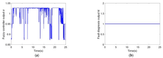
Figure 8.
Robustness simulation results of the drive system fault diagnosis: (a) Fuzzy controller output σ; (b) Fault diagnosis output kl.
Based on the actual torque output expectation collected from the wheel hub motor in Figure 5, noise and fault signals are added to simulate the actual torque output of the motor, as shown in Figure 9. At 4 s, the motor fails, and the drive motor is unable to provide the expected output torque for a long time. The fuzzy controller determines that it has failed, and based on the accumulated diagnosis results, analyzes that it has failed. Therefore, at 4.01 s, the fault diagnosis output result becomes 0, indicating that the motor has failed, as shown in Figure 10. At the same time, when the fault diagnostic output indicates that the motor has failed, it is assumed that the motor may continue to fail in the future. To avoid further damage to the motor caused by frequent failures in the future, the diagnostic result is locked and the power output of the motor is turned off.
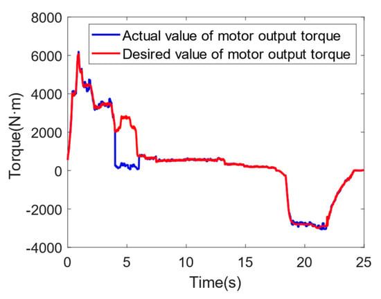
Figure 9.
Actual and expected torque values of fault diagnosis motor output.
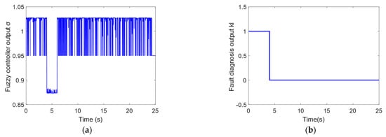
Figure 10.
Simulation results of fault diagnosis for the drive system: (a) Fuzzy controller output σ; (b) Fault diagnosis output kl.
To verify the control effect when a single motor fails, verification was conducted separately for the straight-line driving condition and the single-lateral-lane-shift driving condition. The simulation control group did not deal with the failure situation. The parameters of the two simulation conditions are shown in Table 3. The left front wheel drive motor failed, and the fault factor is shown in Figure 11. A brief torque loss occurred at 0.5 s, and the motor failed for a long time after 1 s.

Table 3.
Simulation condition settings for single-motor failure control.
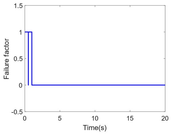
Figure 11.
Simulation verification of failure control based on motor fault factor.
In the straight-line driving condition, the steering wheel angle remains unchanged at 0°, and the simulation stops at a longitudinal displacement of 200 m. The simulation results are shown in Figure 12. In Figure 12a, the final speed of the optimized control group at the end of the simulation is 59.21 km/h, while that of the uncontrolled group is 58.38 km/h. By reconstructing the torque of the normal working motor, the driving force lost by the failed motor can be compensated. Therefore, the final speed of the optimized control group is higher, as shown in Figure 12c, while the uncontrolled group in Figure 12d maintains its original torque output. Figure 12b shows that reconstructing the torque can keep the vehicle in a straight line, with a maximum lateral offset of 0.1 m, while the maximum lateral offset of the uncontrolled vehicle has reached 5.98 m, significantly deviating from the expected straight-line trajectory. Figure 12e shows the deviation in the yaw rate between the two groups of vehicles under the current simulation conditions, which is within a small range. The stability performance of both groups of vehicles is good. Since the control strategy proposed in this paper is more focused on tracking the yaw rate within the stable region, the average deviation in the optimized control group’s yaw rate is 0.0002 rad/s, while that of the uncontrolled group is 0.0047 rad/s. The optimized control group’s tracking of the yaw rate is more accurate.
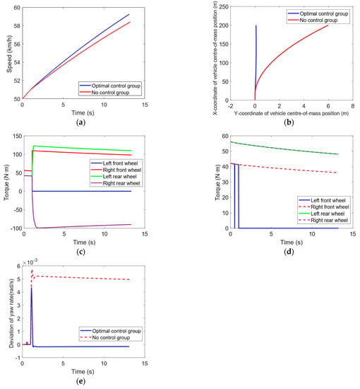
Figure 12.
Simulation results for single-motor failure straight-line driving condition: (a) vehicle speed; (b) vehicle trajectory; (c) optimal control of individual wheel torques; (d) no control of individual wheel torques; (e) deviation in yaw rate.
The steering wheel angle in the single-lane-shift condition is shown in Figure 13:
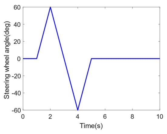
Figure 13.
Steering wheel angle input in the single-motor failure single-lane-shift condition.
The simulation results of the single-motor failure single-lane-shift condition are shown in Figure 14. From Figure 14a, it can be seen that the final speed of the optimized control group is 50.55 km/h, while that of the uncontrolled group is 50.27 km/h. Both groups of vehicles can maintain their speed almost unchanged during the driving process. In Figure 14b, the maximum lateral offset of the optimized control group during the single-lane-shift process is 0.67 m compared to the normal driving, which can keep the expected trajectory of the single-lane shift, while that of the uncontrolled group is 1.01 m, and the trajectory has already deviated from the expected single-lane-shift trajectory. The lateral deviation will gradually increase with time. Figure 14c,d show the torque output of each wheel of the two groups of vehicles. The optimized control group detects the failure of the left front motor, isolates and shuts off its power output, and adjusts the torque of the remaining motors to ensure driving stability. Figure 14e shows the deviation in the yaw rate of the two groups of vehicles during driving, with an average value of 0.016 rad/s for the optimized control group and 0.022 rad/s for the uncontrolled group. Adopting failure control can improve the yaw stability of the vehicle during turning.
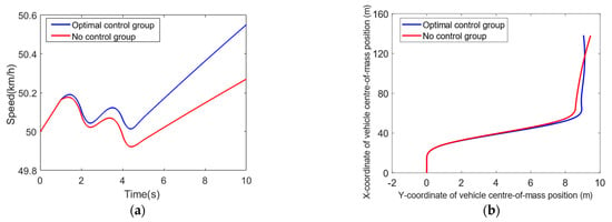
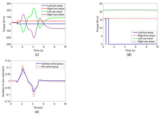
Figure 14.
Simulation results for single-motor failure with single-lane shift: (a) vehicle speed; (b) vehicle trajectory; (c) optimal control of individual wheel torques; (d) no control of individual wheel torques; (e) deviation in yaw rate.
The effectiveness of the failure control strategy for double-motor failure with different axles and sides is verified, where the failed motors are the left front wheel motor and the right rear wheel motor. The simulation results of the straight-line driving condition are shown in Figure 15. From Figure 15a, it can be seen that the final speed of the optimized control group is 60.31 km/h, while that of the uncontrolled group is 54.63 km/h, because two motors have failed, the uncontrolled group has lost a significant amount of power, and the optimized control group can compensate for the lost driving force by the normal working motors, thus achieving a higher final speed. In Figure 15b, the maximum lateral offset of the optimized control group is 0.02 m, while that of the uncontrolled group is 2.11 m, indicating that reconstructing the torque can keep the vehicle in a straight line, while the uncontrolled vehicle will have a much larger lateral deviation. However, due to the normal working of the remaining motors, a certain lateral force moment will still be generated, resulting in a relatively smaller lateral deviation compared to the case of single-motor failure. Figure 15e shows the deviation in the yaw rate of the two groups of vehicles, with an average deviation of 0.0001 rad/s for the optimized control group and 0.0016 rad/s for the uncontrolled group, similar to the performance with single-motor failure. The optimized control group can better track the expected yaw rate, and both groups of vehicles are within the stable region.
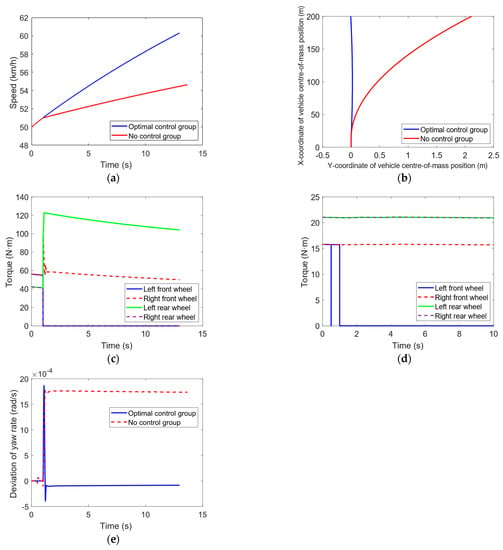
Figure 15.
Simulation results of double-motor failure on the opposite side of the opposite axis under the straight-line driving condition: (a) vehicle speed; (b) vehicle trajectory; (c) optimal control of individual wheel torques; (d) no control of individual wheel torques; (e) deviation in yaw rate.
To make the comparison more obvious, the duration of the single-lane-shift condition simulation is set to 20 s, and the simulation results are shown in Figure 16. From Figure 16a, it can be seen that the final speed of the optimized control group is 52.24 km/h, while that of the uncontrolled group is 48.38 km/h. Similar to the straight-line driving condition, the uncontrolled group will lose some power, and the optimized control group can meet the driver’s power demand. In Figure 16b, the lateral deviation in the optimized control group compared to normal driving during the driving process is 0.52 m, which can maintain the expected single-lane-shift trajectory, while that of the uncontrolled group is 1.84 m, and the trajectory has already deviated from the expected single-lane-shift trajectory. The lateral deviation will gradually increase with time. Figure 16c,d show the torque output of each wheel of the two groups of vehicles. The optimized control group adjusts the torque of the other two normal working motors on the diagonal to improve driving stability. Figure 16e shows the deviation in the yaw rate of the two groups of vehicles during driving, with an average value of 0.0083 rad/s for the optimized control group and 0.01 rad/s for the uncontrolled group. Adopting failure control can improve the yaw stability of the vehicle during turning.
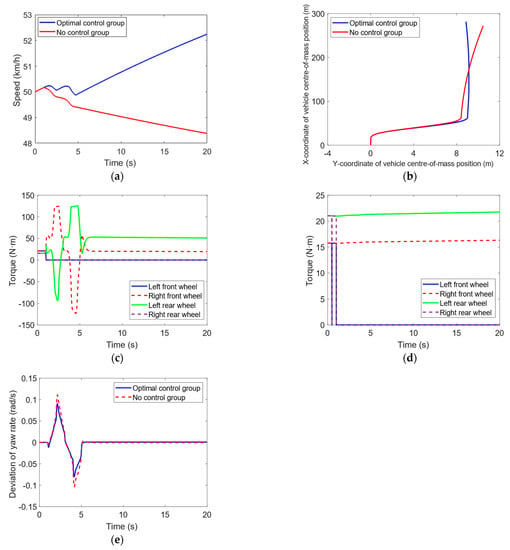
Figure 16.
Simulation results of double-motor failure on the opposite side of the opposite axis under single-lane-shift condition: (a) vehicle speed; (b) vehicle trajectory; (c) optimal control of individual wheel torques; (d) no control of individual wheel torques; (e) deviation in yaw rate.
The simulation results for the two failure modes under straight-line driving and single-lane-shift driving conditions are presented in Table 4. This failure control strategy effectively diagnoses the occurrence of failures, exhibits robust performance, and successfully isolates the failed motors while reconstructing the torque of the remaining motors based on the specific failure mode, ensuring both driving stability and power demand.

Table 4.
Failure control simulation results.
3.2. Hardware-in-the-Loop Simulation Results
To further verify the effectiveness of the failure control strategy in an actual vehicle control unit (VCU), HIL testing was conducted. In this paper, a hardware-in-the-loop simulation platform based on NI PXI and CARSIM RT was constructed, as shown in Figure 17. The platform is seamlessly integrated with the Simulink control model in SIL for co-simulation. It consists of three main parts: the host computer, the tested VCU hardware, and the industrial PC cabinet equipped with real-time processors and digital-to-analog input and output boards.
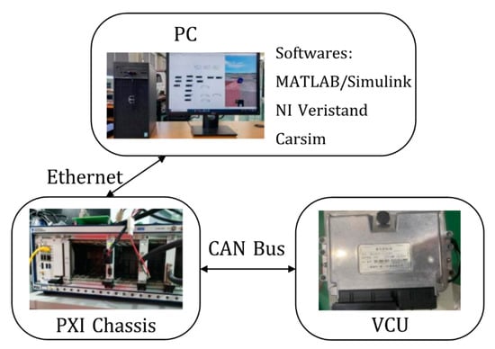
Figure 17.
HIL testing platform.
Due to the inconsistency between the simulation cycle and the communication cycle of HIL testing, the threshold for fault determination needs to be adjusted during HIL testing to adapt to the actual controller. The minimum sampling period of the constructed HIL testing platform was recorded as 10 ms. Therefore, the judgment period was set to 100 ms. If the number of times when σ was less than 0.95 during the judgment period exceeded eight, it was determined that the drive motor had failed and isolation processing was needed.
The actual output torque of the drive motor shown in Figure 5 and the expected output torque were used as inputs to the fault diagnostic tool for HIL testing, as shown in Figure 9. The test result is shown in Figure 18. Figure 18a is the output σ of the designed fault diagnostic tool, while Figure 18b always outputs kl = 1, indicating that the motor is in normal working condition. The HIL test results have demonstrated that the designed fault diagnostic tool has good robustness which can avoid misjudgment caused by torque loss due to transient signal fluctuations. For Figure 18c,d, when the motor fails at 4 s, the drive motor cannot provide the expected output torque for a long time. The fuzzy controller determines that the motor has failed, and based on the cumulative judgment result, the fault diagnostic output results indicate that it has failed at 4.08 s. This is consistent with the simulation results. The HIL test results have demonstrated that the designed fault diagnostic tool can still diagnose whether the motor has failed in a timely and accurate manner in actual controllers. Compared with the simulation results, the influence of signal fluctuations is reduced due to the different sampling frequencies of the controller and the CAN communication frequency, which is the reason why the threshold needs to be adjusted according to the sampling frequency of the controller and the CAN communication frequency.
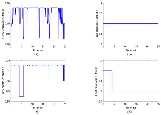
Figure 18.
Drive system fault diagnosis HIL test results: (a) Fuzzy controller output for fault diagnosis σ; (b) Failure factor kl; (c) Fuzzy controller output for fault diagnosis σ; (d) Failure factor kl.
To verify the consistency between HIL testing and the simulation results, the test was conducted using the operating conditions in Table 3. The HIL test under the condition of a single-motor failure in straight-line driving is shown in Figure 19. The results of the HIL test are consistent with the simulation results; when the lateral angular velocity deviation is in a small range in a stable situation, the average value of the lateral angular velocity deviation optimized by the control group is 0.0005 rad/s, while that of the uncontrolled group is 0.0047 rad/s. The control group can track the lateral angular velocity more accurately. By reconstructing the torque of the non-failed motor, the expected power of the driver can be guaranteed, and the final speed of the optimized control group is higher than that of the uncontrolled group. At the same time, adopting failure control can ensure that the vehicle travels along the expected straight trajectory, with a maximum lateral deviation of 0.01 m, whereas the maximum lateral deviation of the uncontrolled vehicle is 5.99 m.
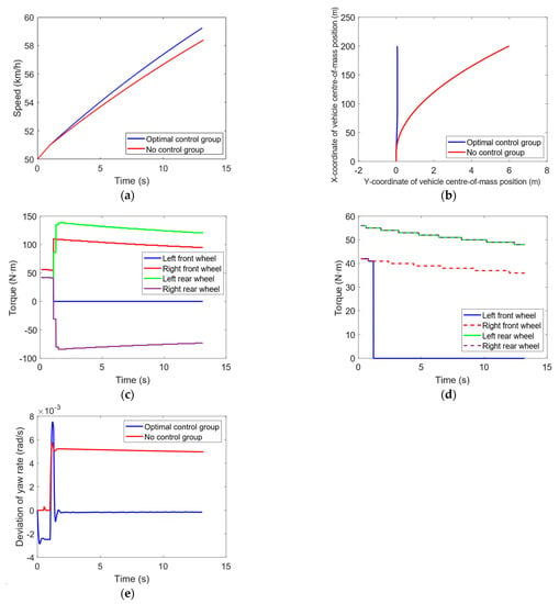
Figure 19.
HIL test results for single-motor failure in straight-line operation: (a) vehicle speed; (b) vehicle trajectory; (c) optimal control of individual wheel torques; (d) no control of individual wheel torques; (e) deviation in yaw rate.
The simulation of a single-motor failure in a single-lane-shift condition is shown in Figure 20. Both groups of vehicles can maintain a speed of around 50 km/h, but the trajectory of the uncontrolled vehicle gradually deviates from the expected single-lane-shift trajectory, while the optimized control group can continue to travel on the expected trajectory through adjustment of the torque of each wheel. Figure 20e shows the lateral angular velocity deviation of the two groups of vehicles while driving. The average value of the optimized control group is 0.016 rad/s, while that of the uncontrolled group is 0.022 rad/s. Compared with the uncontrolled group, the optimized control group can reduce the deviation from the expected lateral angular velocity and improve the stability during turning, which is consistent with the simulation results.
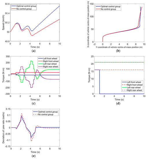
Figure 20.
HIL test results for single-motor failure single-lane-shift condition: (a) vehicle speed; (b) vehicle trajectory; (c) optimal control of individual wheel torques; (d) no control of individual wheel torques; (e) deviation in yaw rate.
The simulation of a straight-line driving condition with dual-motor failure on opposite sides is shown in Figure 21. In Figure 21a, the final speed of the optimized control group is 60.32 km/h, while that of the uncontrolled group is 54.64 km/h. The optimized control group can maintain the expected power. It can be seen from Figure 21b that the maximum lateral deviation of the optimized control group is 0.072 m, which is slightly increased compared to the simulation results, but it can still prevent the vehicle from running off the road. The maximum lateral deviation of the uncontrolled group is 2.111 m, and the vehicle gradually deviates from the straight-line-driving trajectory. Both groups of vehicles are stable. The average lateral angular velocity deviation of the optimized control group is 0.0002 rad/s, while that of the uncontrolled group is 0.0016 rad/s. The lateral angular velocity deviation is improved compared to the uncontrolled group.
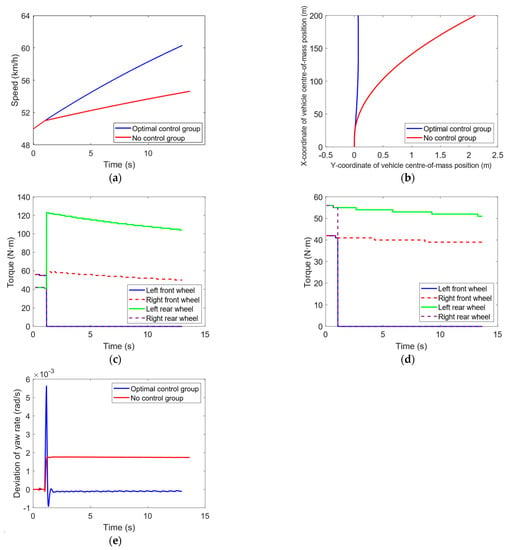
Figure 21.
HIL test results for hetero-shaft and hetero-side dual-motor failure in straight-line driving condition: (a) vehicle speed; (b) vehicle trajectory; (c) optimal control of individual wheel torques; (d) no control of individual wheel torques; (e) deviation in yaw rate.
The simulation of a single-lane-shift working condition with dual motor failure on opposite sides is shown in Figure 22. Similar to the straight-line driving condition in Figure 22a, the uncontrolled group will lose some power and the vehicle speed gradually decreases. The final speed is 48.38 km/h, while the optimized control group can meet the driver’s power requirements, and the final speed is 52.27 km/h. In Figure 22b, the optimized control group can still maintain the expected single-lane-shift trajectory, while the trajectory of the uncontrolled group vehicle has deviated. With time, it will gradually deviate from the expected trajectory. Figure 22e shows the lateral angular velocity deviation of the two groups of vehicles while driving. Both groups of vehicles are in a stable operating region. Due to the two normal working motors on both sides, the uncontrolled group can provide some additional lateral torque, which makes it more stable compared to the single motor failure condition. The average lateral angular velocity deviation of the optimized control group is 0.0082 rad/s, while that of the uncontrolled group is 0.01 rad/s. Adopting failure control can improve the driving stability after dual-motor failure on opposite sides, and the lateral angular velocity deviation is smaller, which is consistent with the simulation results.
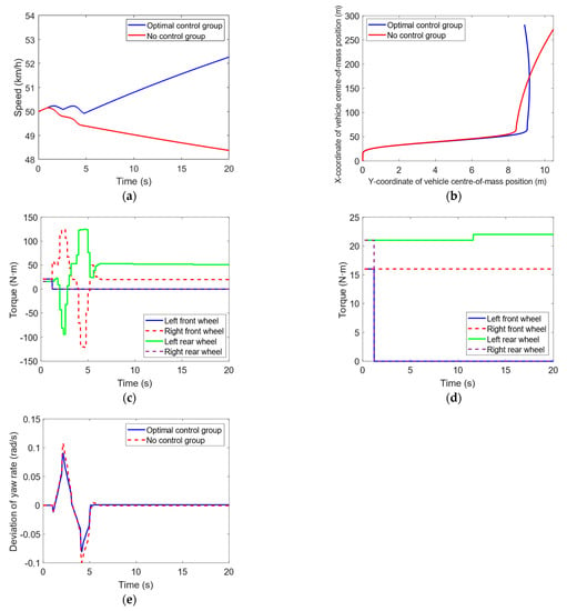
Figure 22.
HIL test results for single-lane-shift condition with dual-motor failure on the opposite shaft and opposite side: (a) vehicle speed; (b) vehicle trajectory; (c) optimal control of individual wheel torques; (d) no control of individual wheel torques; (e) deviation in yaw rate.
The hardware-in-the-loop (HIL) test results for the two failure modes in the respective working conditions are presented in Table 5. These results are consistent with the simulation findings, validating the efficacy of the proposed failure control strategy for the distributed-four-wheel-drive system. The strategy can effectively diagnose drive-system faults in the actual VCU. It can also isolate the faulty motor according to the failure condition and restructure the torque of the remaining non-faulty motors, thus improving the driving stability of the vehicle, maintaining the expected power, and enabling the vehicle to follow the intended driving trajectory.

Table 5.
Failure control HIL test results.
4. Conclusions
The fault-tolerant control strategy designed in this study comprises two key components: fault diagnosis and fault-tolerant control. The actual output torque of the drive motor and the ratio of the expected output torque along with its rate of change are used as inputs to design a fuzzy controller, which produces the motor fault diagnosis result. The accumulated diagnosis results within a specified time period are analyzed to determine if the motor has failed. The fault-tolerant controller identifies the failure mode based on the diagnostic results of the four motors and applies fault-mode rules to restructure the torque of the non-failed motors. This fault-tolerant control strategy effectively mitigates the impact of interference signals, accurately identifies the failed motors and their failure mode, and exhibits robust performance. By adopting torque reconstruction, this strategy can maintain driving power and stability. The software simulation and HIL test results show good consistency, confirming the effectiveness and reliability of the designed control strategy.
Author Contributions
Conceptualization, S.Z.; Software, C.K.; Investigation, H.C. and J.G.; Writing—original draft, H.L.; Writing—review & editing, H.L. and H.C.; Supervision, G.W.; Funding acquisition, W.X. All authors have read and agreed to the published version of the manuscript.
Funding
This research was funded by [Control design of new energy vehicle air conditioning compressor based on intelligent multi-objective optimization] grant number [ZDLQ2020002].
Data Availability Statement
No new data were created or analyzed in this study.
Acknowledgments
The Open Project Program of Fujian Provincial Key Laboratory of Intelligent Identification and Control of Complex Dynamic System (2022A0006); Control design of new energy vehicle air conditioning compressor based on intelligent multi-objective optimization (ZDLQ2020002).
Conflicts of Interest
The authors declare no conflict of interest.
References
- Zhang, X. Modeling and Dynamics Control for Distributed Drive Electric Vehicles; Springer Vieweg: Berlin, Germany, 2021. [Google Scholar] [CrossRef]
- Zhou, H.; Jia, F.; Jing, H.; Liu, Z.; Guvenc, L. Coordinated Longitudinal and Lateral Motion Control for Four Wheel Independent Motor-Drive Electric Vehicle. IEEE Trans. Veh. Technol. 2018, 67, 3782–3790. [Google Scholar] [CrossRef]
- Chen, T.; Chen, L.; Xu, X.; Cai, Y.; Jiang, H.; Sun, X. Passive fault-tolerant path following control of autonomous distributed drive electric vehicle considering steering system fault. Mech. Syst. Signal Process. 2019, 123, 298–315. [Google Scholar] [CrossRef]
- Un-Noor, F.; Padmanaban, S.; Mihet-Popa, L.; Mollah, M.N.; Hossain, E. A Comprehensive Study of Key Electric Vehicle (EV) Components, Technologies, Challenges, Impacts, and Future Direction of Development. Energies 2017, 10, 1217. [Google Scholar] [CrossRef]
- Ding, N.; Taheri, S. An adaptive integrated algorithm for active front steering and direct yaw moment control based on direct Lyapunov method. Veh. Syst. Dyn. 2010, 48, 1193–1213. [Google Scholar] [CrossRef]
- Wang, Z.; Shao, J.; He, Z. Fault Tolerant Sensorless Control Strategy with Multi-States Switching Method for In-Wheel Electric Vehicle. IEEE Access 2021, 9, 61150–61158. [Google Scholar] [CrossRef]
- Wang, R.; Wang, J. Fault-Tolerant Control for Electric Ground Vehicles with Independently-Actuated In-Wheel Motors. J. Dyn. Syst. Meas. Control 2012, 134, 021014. [Google Scholar] [CrossRef]
- Wang, R.; Wang, J. Actuator-Redundancy-Based Fault Diagnosis for Four-Wheel Independently Actuated Electric Vehicles. IEEE Trans. Intell. Transp. Syst. 2013, 15, 239–249. [Google Scholar] [CrossRef]
- Li, C.; Chen, G.; Zong, C.; Liu, W. Fault-tolerant control for 4WID/4WIS electric vehicle based on EKF and SMC. SAE Int. J. Passeng. Cars Electron. Electr. Syst. 2015, 9, 1–8. [Google Scholar] [CrossRef]
- Rkhissi-Kammoun, Y.; Ghommam, J.; Boukhnifer, M.; Mnif, F. New fault-tolerant induction motor control architecture for current sensor fault in electric vehicle. In Proceedings of the 2018 15th International Multi-Conference on Systems, Signals & Devices (SSD), IEEE, Yasmine Hammamet, Tunisia, 19–22 March 2018; pp. 65–70. [Google Scholar]
- Kamen, D.; Morrell, J.B.; Robinson, D.W.; Reich, R.K.; Heinzmann, J.D.; LeMay, P.; Meyer, S.R.; Sachs, J.M.; Field, J.D. Method and System for Fail-Safe Motor Operation. U.S. Patent 6,965,206, 15 November 2005. [Google Scholar]
- Lopes, A.; Araújo, R.E. Fault-tolerant control based on sliding mode for over-actuated electric vehicles. In Proceedings of the 2014 IEEE International Electric Vehicle Conference (IEVC), IEEE, Florence, Italy, 17–19 December 2014; pp. 1–6. [Google Scholar]
- Wang, J.; Gao, S.; Wang, K.; Wang, Y.; Wang, Q. Wheel torque distribution optimization of four-wheel independent-drive electric vehicle for energy efficient driving. Control Eng. Pract. 2021, 110, 104779. [Google Scholar] [CrossRef]
- Xin, X.; Zheng, H.; Xu, H.; Qin, G. Control strategies for four in-wheel drove electric vehicles when the motor drive systems fail. In Proceedings of the 2014 American Control Conference, IEEE, Portland, OR, USA, 4–6 June 2014; pp. 885–890. [Google Scholar]
- Sun, X.; Shi, Z.; Cai, Y.; Lei, G.; Guo, Y.; Zhu, J. Driving-Cycle-Oriented Design Optimization of a Permanent Magnet Hub Motor Drive System for a Four-Wheel-Drive Electric Vehicle. IEEE Trans. Transp. Electrif. 2020, 6, 1115–1125. [Google Scholar] [CrossRef]
- Wanner, D.; Wallmark, O.; Jonasson, M.; Drugge, L.; Trigell, A.S. Control allocation strategies for an electric vehicle with a wheel hub motor failure. Int. J. Veh. Syst. Model. Test. 2015, 10, 263. [Google Scholar] [CrossRef]
- Lee, K.; Lee, M. Fault-Tolerant Stability Control for Independent Four-Wheel Drive Electric Vehicle Under Actuator Fault Conditions. IEEE Access 2020, 8, 91368–91378. [Google Scholar] [CrossRef]
- Liu, L.; Shi, K.; Yuan, X.; Li, Q. Multiple model-based fault-tolerant control system for distributed drive electric vehicle. J. Braz. Soc. Mech. Sci. Eng. 2019, 41, 531. [Google Scholar] [CrossRef]
Disclaimer/Publisher’s Note: The statements, opinions and data contained in all publications are solely those of the individual author(s) and contributor(s) and not of MDPI and/or the editor(s). MDPI and/or the editor(s) disclaim responsibility for any injury to people or property resulting from any ideas, methods, instructions or products referred to in the content. |
© 2023 by the authors. Licensee MDPI, Basel, Switzerland. This article is an open access article distributed under the terms and conditions of the Creative Commons Attribution (CC BY) license (https://creativecommons.org/licenses/by/4.0/).