1. Introduction
Magnetic shape-memory alloys (MSMAs) are multifunctional materials that offer both thermal shape-memory, magnetic properties, as well as various multiferroic coupling effects [
1]. The unique features of MSMAs are due to pronounced magnetic ordering and large magnetocrystalline anisotropy, resulting in an energetically preferred orientation of magnetic moments. In addition, MSMAs undergo a first-order martensitic phase transformation, which involves a large abrupt change in both the structural and magnetic properties. The phase transformation proceeds in a reversible manner, enabling a thermal shape-memory effect as well as superelasticity. The presence of coupled ferromagnetic and metastable ferroelastic (martensitic) domains in MSMA materials gives rise to multiferroic coupling effects, such as magnetic field-induced reorientation and magnetic shape-memory effect [
2]. A prominent example is the Heusler alloy Ni-Mn-Ga [
2,
3,
4], which is ferromagnetic at room temperature. Metamagnetic SMAs, such as the quaternary Heusler alloys Ni–Mn–X–Y (X = Ga, In, Sn; Y = Co, Fe, Al), are non-magnetic or antiferromagnetic in the martensitic state at low temperatures and undergo an abrupt change of magnetization with narrow hysteresis at the first-order transformation to the austenitic state [
5].
Due to these properties, MSMAs exhibit different modes of combined sensing and actuation capabilities [
6,
7]. As a consequence, MSMA actuators may be designed as a single piece of material but may still perform various functions. This option is particularly interesting for applications in small dimensions, where the effect size, multifunctionality, and ease of fabrication are important factors. Previous approaches to the development of miniature-scale MSMA actuators include the thinning of bulk single crystals to foil specimens [
8,
9], the deposition of MSMA films [
10,
11,
12], as well as 3D printing [
13]. So far, several actuation mechanisms have been exploited at miniature scales. MSMA linear actuators have been developed using the magnetic field-induced reorientation effect in single crystalline Ni–Mn–Ga [
14,
15,
16,
17]. A bidirectional microactuator has been developed consisting of a polycrystalline Ni–Mn–Ga double-beam cantilever, which generates antagonistic bending forces near a miniature permanent magnet due to an electrical current-induced transition between ferromagnetic martensite and paramagnetic austenite. Thus, pulsed heating causes fast oscillatory motion of the cantilever in microscanner applications [
18]. The abrupt change of magnetization in the first-order phase transformation in metamagnetic SMA films has been considered in [
19,
20] to enable thermally induced switching of magnetic forces.
Another field of application of MSMA actuation is thermomagnetic generation (TMG) at miniature scales [
21,
22,
23,
24,
25]. Film-based TMGs have been developed using metamagnetic [
22] and ferromagnetic SMA films [
23,
24,
25]. The MSMA film actuator was integrated at the front of a freely movable cantilever near a heatable permanent magnet serving at the same time as the magnetic field and heat source. In this case, due to the large surface-to-volume ratio, rapid heat transfer is achieved through direct mechanical contact between the MSMA film and heat source, enabling a short duration of the thermal duty cycle in the order of the mechanical eigenoscillation. When heating the permanent magnet above the Curie temperature Tc, this performance gives rise to resonant self-actuation, which is characterized by a large cantilever deflection and a high oscillation frequency [
24,
25]. Recent demonstrators based on Heusler alloy films of Ni-Mn-Ga showed oscillation frequencies in the order of 100 Hz. By integrating a pick-up coil at the cantilever front, electrical power densities of up to 120 mW/cm
3 have been generated [
24,
25].
In this investigation, we extend this approach by integrating two MSMA film actuators on opposite sides of the cantilever front and using two heatable permanent magnets above and below the cantilever to form a bistable actuation system. Bistable systems are of special interest both for actuation, as energy is only consumed in case of switching, and for energy harvesting, as the power output could be enhanced by the additional bistable forces. A lumped-element model (LEM) is presented to determine the magneto-mechanical performance of the new actuator design as a function of the MSMA film temperature, which complements the experimental study of the dynamic mechanical actuator performance.
We demonstrate that the MSMA film actuator shows bistable switching between two stable end positions due to thermally induced switching of magnetic latching forces, which transitions to resonant self-actuation in between the end positions when continuously heating the permanent magnets above Tc. We report on large oscillation strokes in the order of 20% of the cantilever length at oscillation frequencies of 50–60 Hz, which allows for thermomagnetic generation with a power per footprint of up to 2.3 µW/cm2.
2. Material Properties
Sputtering is the most favorable deposition method to obtain thick films on a large scale, as is required for MEMS technology [
6,
12]. The resulting film structure depends on various parameters including the substrate, deposition temperature, sputtering power, and annealing conditions. Consequently, the as-prepared films can exhibit a polycrystalline structure [
26,
27,
28] or an epitaxial relation to the substrate [
10,
29]. A process has been developed for the fabrication of freestanding polycrystalline Ni–Mn–Ga films showing 10 M martensite at room temperature [
26,
30]. Here, the MSMA films are fabricated by magnetron sputtering with the target composition of Ni
49.5Mn
28Ga
22.5. Film deposition is performed on polyvinyl alcohol (PVA) substrates that can be dissolved after sputtering. A sputtering power of 200 W is used and the sputtering time is adjusted to obtain a homogenous film thickness of 10 µm. Argon gas flow is maintained at 230 mm
3 s
−1, and the substrate temperature is kept at 50 °C. Under these conditions, the as-deposited films are amorphous and require heat treatment to adjust the crystal structure and phase transformation properties. The effect of heat treatment on the performance of polycrystalline Ni–Mn–Ga films is described in [
26]. The final composition after heat treatment of 10 h at 800 °C is determined by the inductive plasma method to be Ni
51.4Mn
28.3Ga
20.3.
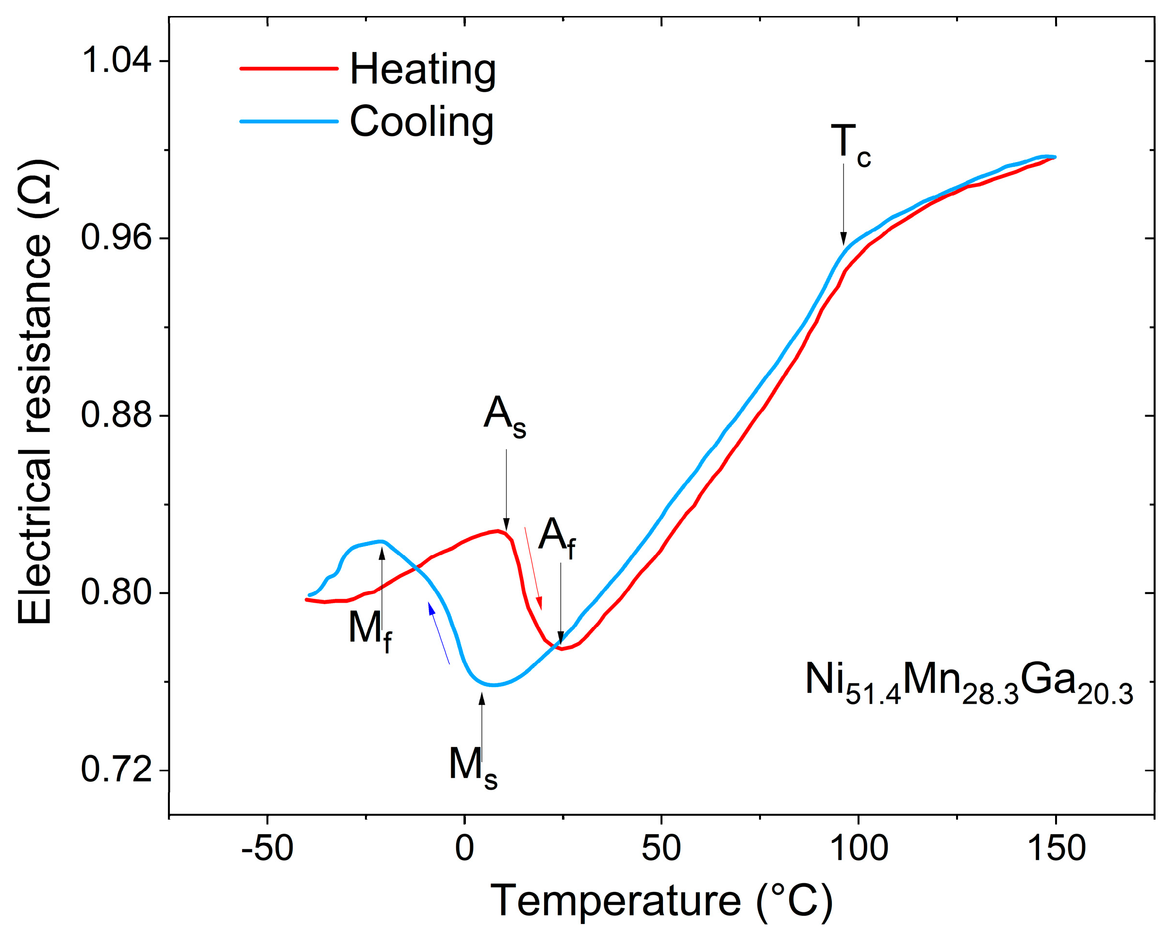
Our investigations showed that the sputtering power can be used as a means to control the chemical composition of the films. Therefore, the Ni and Mn contents of the films decrease with increasing sputtering power for both targets, whereas the Ga content increases. However, little change in composition is observed for different heat treatment temperatures between 650 and 1000 °C and heat treatment times between 1 h and 10 h. A temperature-dependent measurement of the electrical resistance is shown in
Figure 1. The measurement reveals the typical features of a first-order martensitic phase transformation, namely, a jump-like drop upon heating and a hysteresis upon subsequent cooling. The finish temperatures of the martensitic and austenitic transformations,
Mf/
Af, are determined to be −20/25 °C. The measurement also exhibits a characteristic kink at 98 °C due to the ferromagnetic transition. Typical temperature-dependent magnetization characteristics are shown in the
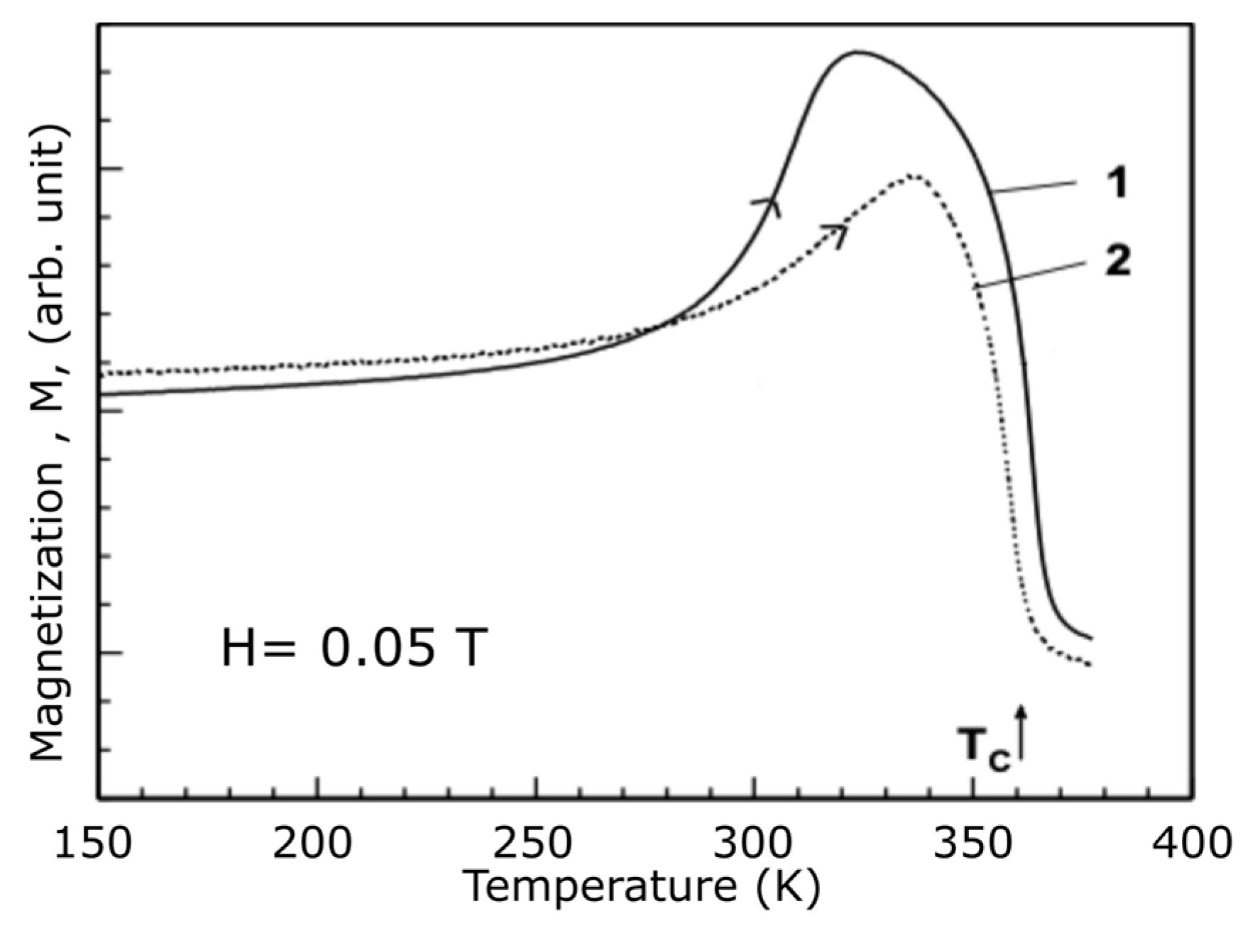
Appendix A (
Figure A1). When heating the Ni-Mn-Ga films above
Tc, the magnetization drops to zero, which will be used in the following to control the magnetic attraction forces.
3. Layout and Operation Principle
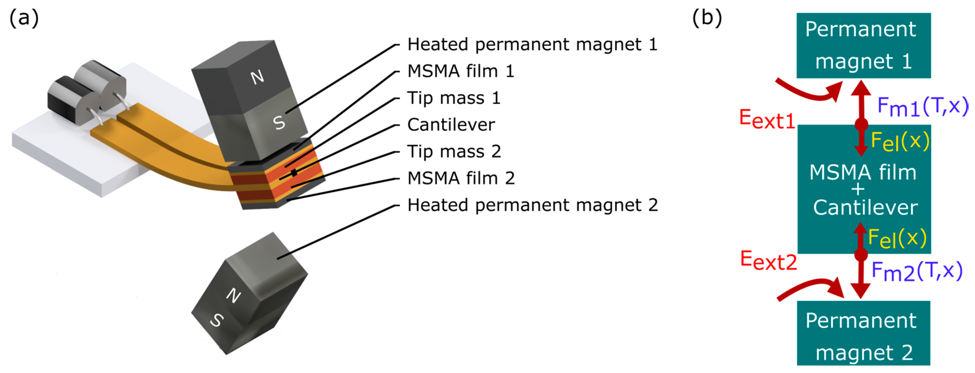
The bistable actuator comprises two MSMA films that are mounted at the tip of a free-standing cantilever on either side, as shown in
Figure 2a. Furthermore, two permanent magnets are arranged above and below the cantilever, providing magnetic fields to magnetize the MSMA films and magnetic field gradients to induce magnetic attraction forces on the MSMA films. These magnetic forces can be varied in a wide range by increasing/decreasing the temperature of the MSMA films above/below their Curie temperature
Tc. The magnets are placed at an angle on both sides of the cantilever to achieve maximum contact. The coupling of the elastic and magnetic forces,
Fel and
Fm, in the system is illustrated schematically in
Figure 2b. This coupling gives rise to bistable performance, i.e., the system can adopt two stable deflection states, whereby external energy is required to switch between these states. When providing sufficient external energy in the form of mechanical vibration, for instance, the cantilever tip would oscillate between the two deflection states. Here, we consider the supply of thermal energy.
One operation mode is bistable switching by the selective heating of the MSMA films. At room temperature, the MSMA films are in a ferromagnetic state and, therefore, the cantilever is attracted to either of the two permanent magnets. Any asymmetry results in a preferred initial deflection state. Selective heating of the MSMA film being in contact with its corresponding magnet above Tc causes a reduction in magnetization and a decrease in the magnetic attraction force Fm until it drops below the restoring force of the cantilever Fel. In this case, the contact is released and the cantilever deflects back towards its initial straight position. Due to inertial forces, the cantilever overshoots and is attracted to the opposite permanent magnet. Due to symmetry, resetting occurs when selectively heating the opposite MSMA film.
The second operation mode is a thermally induced oscillation between the two deflection states. In this case, both MSMA films are heated alternately in a periodic manner, which is easily accomplished by continuously heating the permanent magnets and maintaining their temperature above Tc. Then, the heating of the MSMA films occurs by direct contact with the heated magnets. Periodic heating and cooling of the MSMA films cause an oscillatory motion of the cantilever, as long as the thermal energy supply is maintained.
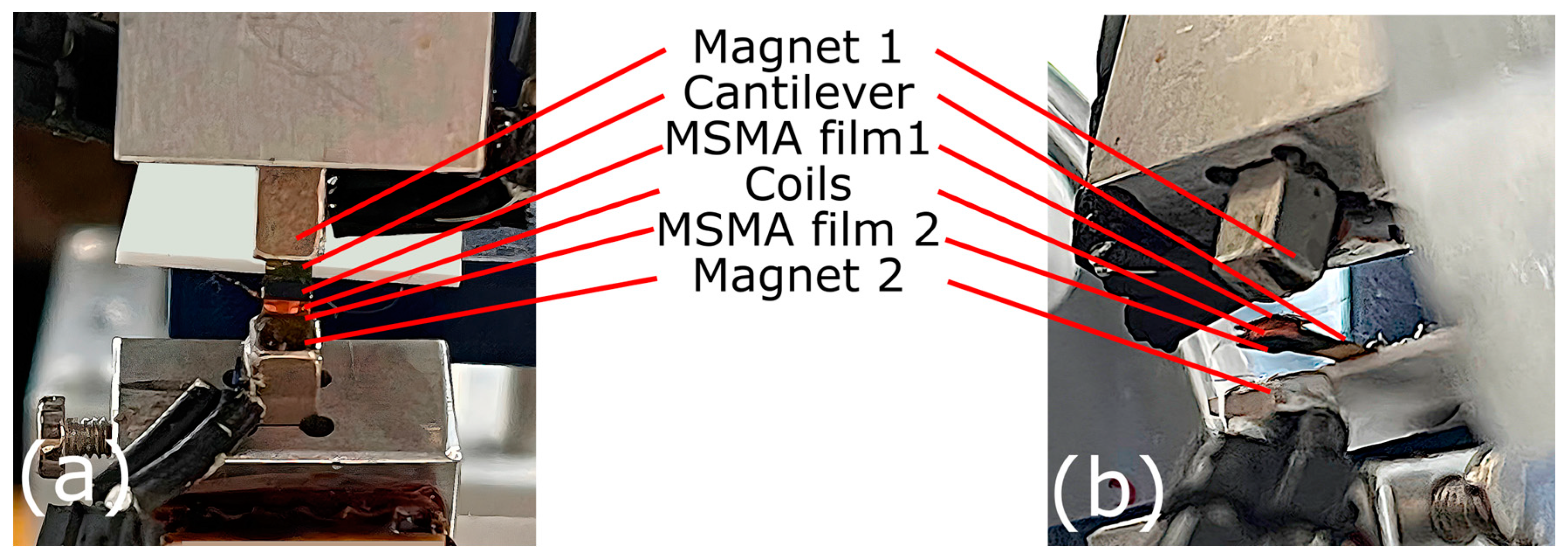
The cantilever is fabricated by laser micromachining of a CuZn film of 20 µm thickness. The inertial forces in the system are adjusted by providing additional tip masses on either side of the cantilever. The two MSMA films of Ni-Mn-Ga are attached on top of the respective tip masses, allowing for thermal decoupling from the cantilever beam. A photo of the final device is presented in the
Appendix A.
4. Lumped Element Modelling of Performance
A lumped element model (LEM) in Matlab SIMSCAPE 2022b is introduced to describe the coupled magneto-thermo-mechanical coupling within the device and to optimize the performance parameters. If a small lateral displacement of the cantilever is neglected, the bending motion of the cantilever can be assumed to be one-dimensional. Thus, a spring mass damper system can be used to represent the dynamic motion of the microactuator. At the miniature scale, the gravitational force on the system can be neglected as well. Thus, the effective net force
acting on the movable masses
of the cantilever tip is described by the force balance as follows:
whereby
is approximated by
The parameters
and
represent the masses of the cantilever and the magnetic SMA films, respectively.
and
denote the damping coefficient and the spring constant of the structure, respectively. The attraction force between the magnetic SMA films and the permanent magnets is denoted by
, which is a function of both position and temperature.
Thereby,
denotes the volume of the MSMA films that are magnetized by the applied field of the permanent magnet.
is the magnetization of the films as a function of temperature and magnetic field, which is mapped experimentally as a function of the position of the two films. The position dependencies are used to determine the magnetic field gradients
analytically [
31]. Since there are two magnets, the magnetic fields and field gradients are superimposed to calculate the resulting magnetic field at a given position.
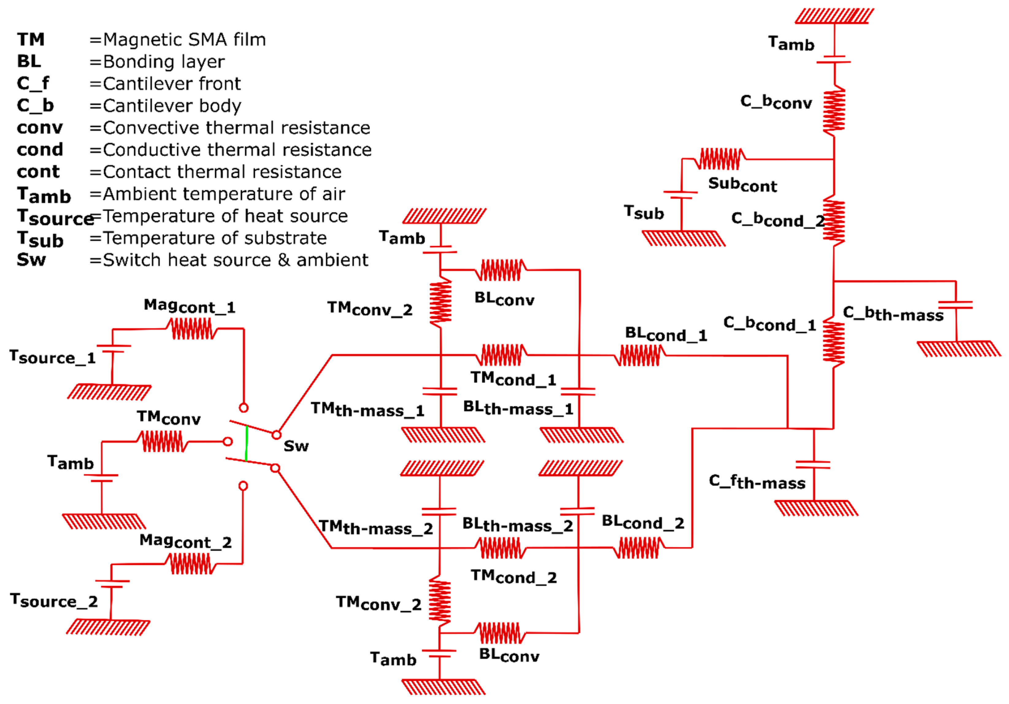
The heat transfer at contact and the thermal dissipation during actuation are modeled by using thermal equivalent circuits. A Cauer model is utilized for representing different components of the device as a combination of thermal resistance and thermal capacitance [
32].
Figure 3 shows a schematic of the thermal network of the bistable magnetic SMA microactuator device. The overall impedance of the system governs its heat intake and dissipation. This is given by Equation (4), where
is the overall thermal impedance of the device, R
th(i) is the thermal resistance, and C
th(i) (i = 1, 2, 3 … n) is the thermal capacitance of the individual components, respectively. In order to obtain the thermal gradient within the individual components, each component is represented by a combination of several thermal resistances and capacitances with a resolution proportional to the number of resistances and capacitances representing one component. Depending on the dimensions of each component and thermal properties, the heat flow and dynamic temperature change are obtained [
32].
Coupling both the thermal circuit model and the mechanical spring damper model allows for the time-resolved simulation of the thermal performance, as well as the dynamic actuation of the bistable device. In order to compare different multistable nonlinear systems and quantify their stability, a model-based description of the involved energies is appropriate. This allows the determination of available stable states at the energy minima and the energy barrier that needs to be overcome in order to switch between the states.
5. Resonant Self-Actuation
When continuously heating the permanent magnets above
Tc, the cantilever undergoes an oscillatory motion, which is governed by the interplay of magnetic attraction, elasticity, inertia, and damping forces. In particular, the dynamics of heat transfer have an important influence on the oscillation performance. If heat transfer from the heated magnet to the MSMA film is slower than the duration of the cantilever eigen oscillations, the cantilever will rest at the magnet and possibly perform damped eigen oscillations until the magnetic attraction force decreases enough after a sufficient heating time of the MSMA film to retract from the magnet. On the other hand, if the cooling of the MSMA film is too slow to be attracted to the magnet surface, it will undergo chaotic oscillations without touching the magnet until the attraction force of one of the magnets is sufficiently large. In the optimum case, however, matching the time constants of heat transfer and mechanical oscillation will lead to resonant self-actuation [
33]. In the present actuator design, the dimensions of the MSMA films are adjusted for a sufficiently large surface-to-volume ratio, and the eigenfrequency of the moving mass is tuned to meet the matching conditions. Once the coupled thermo-magneto-mechanical cycles are balanced, resonant self-actuation occurs, which is characterized by a continuous periodic oscillation with large strokes and high frequencies.
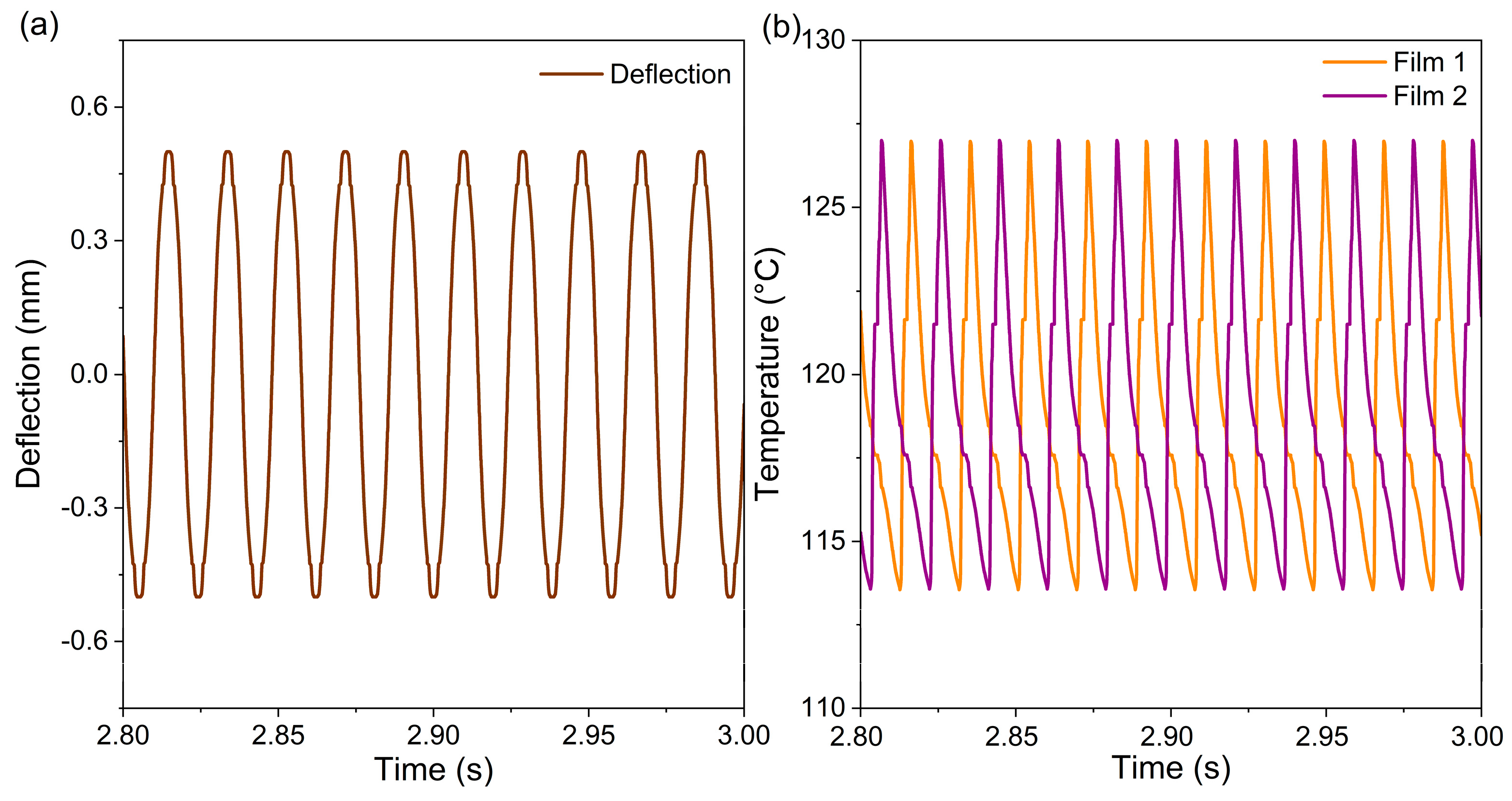
Figure 4a shows the simulated time-resolved deflection of the cantilever tip in resonant self-actuation mode. The corresponding time-resolved changes in the MSMA film temperatures are shown in
Figure 4b.
Due to the symmetry of the bistable MSMA film actuator, the cantilever tip performs equal deflections in positive and negative directions. As the MSMA films are heated alternately while in contact with the permanent magnets, they undergo separate thermal cycles with a phase shift of 180 degrees for each mechanical cycle. The experimental results on the time-dependent performance of the bistable MSMA film actuator are presented in
Section 7. Due to the constraints of the experimental setup, time-resolved measurements of the actuator deflections were not possible. Therefore, the simulation model was validated using temperature-dependent electrical measurements (see
Section 7).
6. Transition from Bistable Switching to Resonant Self-Actuation
Once the permanent magnets are continuously heated above Tc, the bistable MSMA film actuator undergoes a transition from bistable switching to resonant self-actuation. Next, this transition is analyzed via LEM simulations of the evolution of magnetic attraction forces and the corresponding potential energies.
The magnetic attraction forces acting on the MSMA films 1 and 2 (
Fm1 and
Fm2) result in an effective force <
F> acting on the cantilever tip.
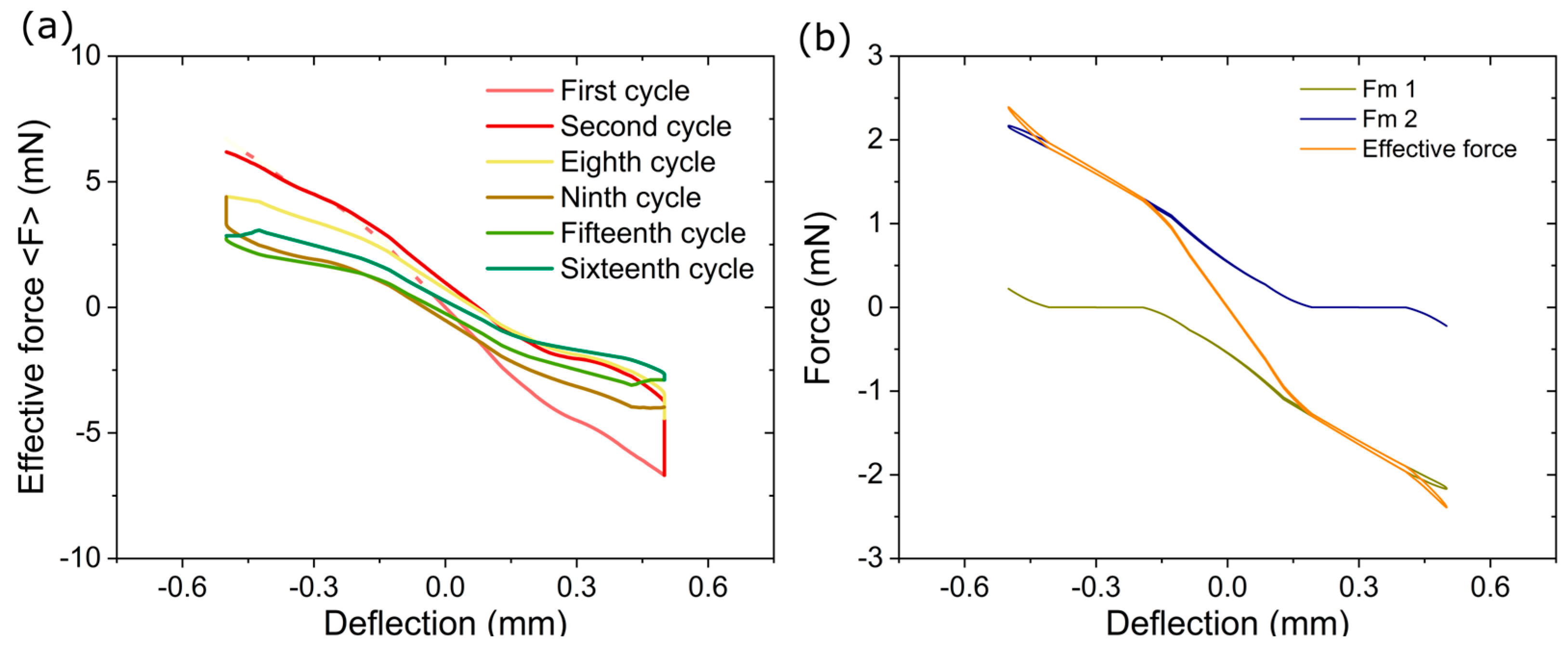
Figure 5a shows the simulated change in the effective magnetic attraction force <
F> versus cantilever deflection during the initial oscillation cycles before the MSMA film actuator reaches stationary operation conditions. In the first actuation cycle, the microactuator switches from the initial stable state at −0.5 mm to the second stable state at 0.5 mm, where it rests until selective heating of the MSMA film at contact with the magnet causes the microactuator to switch back to the initial position in the second actuation cycle. Within the first 16 cycles, the system transitions from the initial bistable switching mode to the resonant self-actuation mode. Thereby, the effective force maxima <
Fmax> at the permanent magnets decrease from ±6.5 mN to about ±2.5 mN. This reduction is caused by an increase in the average temperatures of the MSMA films until they reach stationary values.
Figure 5b shows the magnetic attraction forces
Fm1 and
Fm2, as well as the resulting effective magnetic force <
F> under stationary operation conditions.
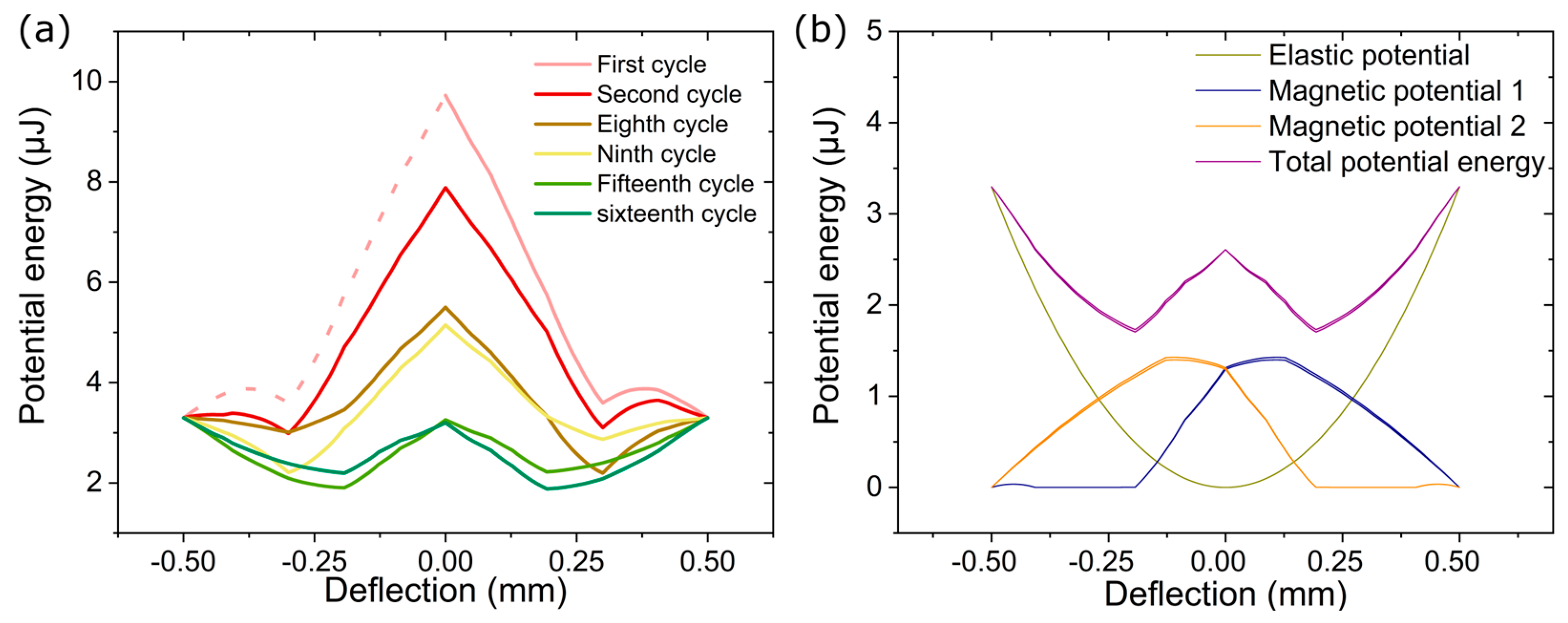
Figure 6 shows the corresponding simulated changes in the potential energies, whereby the total potential energy comprises the contributions of the elastic potential energy of the cantilever and the magnetic potential energies of the two magnetic subsystems.
Figure 6a depicts the change in the total potential energy versus deflection of the cantilever tip during the initial oscillation cycles before the MSMA film actuator reaches stationary operation conditions. The dotted line in
Figure 6a indicates the symmetry of the total potential energy in the initial state. In the simulation, the initial position is at zero deflection in the center between the permanent magnets, where the potential energy shows a pronounced maximum of about 10 µJ. In addition, two potential minima occur at the surfaces of the two permanent magnets, which correspond to the two stable deflection states of the actuator. Without a continuous supply of thermal energy, the MSMA film actuator would deflect towards one of the two deflection states and rest. The continuous supply of thermal energy during the contact between the MSMA films and their respective permanent magnets strongly affects the potential energies. Within the first 16 cycles, the maximum potential energy decreases considerably to less than 3 µJ. Simultaneously, two pronounced potential energy minima evolve on either side of the actuator center, whereby they become increasingly pronounced and propagate towards the actuator center until they become stationary at about ±2 µm. This reduction is caused by an increase in the average temperatures of the MSMA films, which affects the magnetic forces (
Figure 5) alike.
Figure 6b shows the potential energies of both magnetic subsystems, the elastic energy, and the resulting total energy versus deflection once stationary conditions are reached. In this case, the total energy exhibits two energy minima well apart from the maximum possible deflection states and a small energy barrier in the actuator center, which is sufficiently low to enable continuous oscillation. Continuous oscillations occur as long as the kinetic energy of the moving mass exceeds the barrier height. Therefore, a critical upper limit of the elastic potential energy exists, above which the energy barrier becomes too high for resonant self-actuation.
7. Bistable Thermal Energy Harvesting Based on Resonant Self-Actuation
The bistable MSMA film actuator is highly attractive for thermal energy harvesting, as the operation mode of resonant self-actuation enables an optimum conversion of thermal energy into kinetic energy of mechanical eigenoscillation. By integrating two pick-up coils, 1 and 2, next to the MSMA films 1 and 2, respectively, instead of the tip masses, a symmetric energy harvester design is obtained. The core of the pick-up coil is made of copper to allow thermal conduction between the MSMA film and the cantilever. The outer sides of the coils are made of brass. The dimensions of the Cu core and brass layers are tailored for optimum heat transfer, following the guidelines given in [
33]. To simulate the energy harvesting performance, the LEM is extended to include the electromagnetic coupling of the movable pick-up coil following the approach in [
34]. In this case, the time-dependent performance of the bistable MSMA film actuator can be determined via LEM simulations and electrical measurements, which allows the validation of the simulation model.
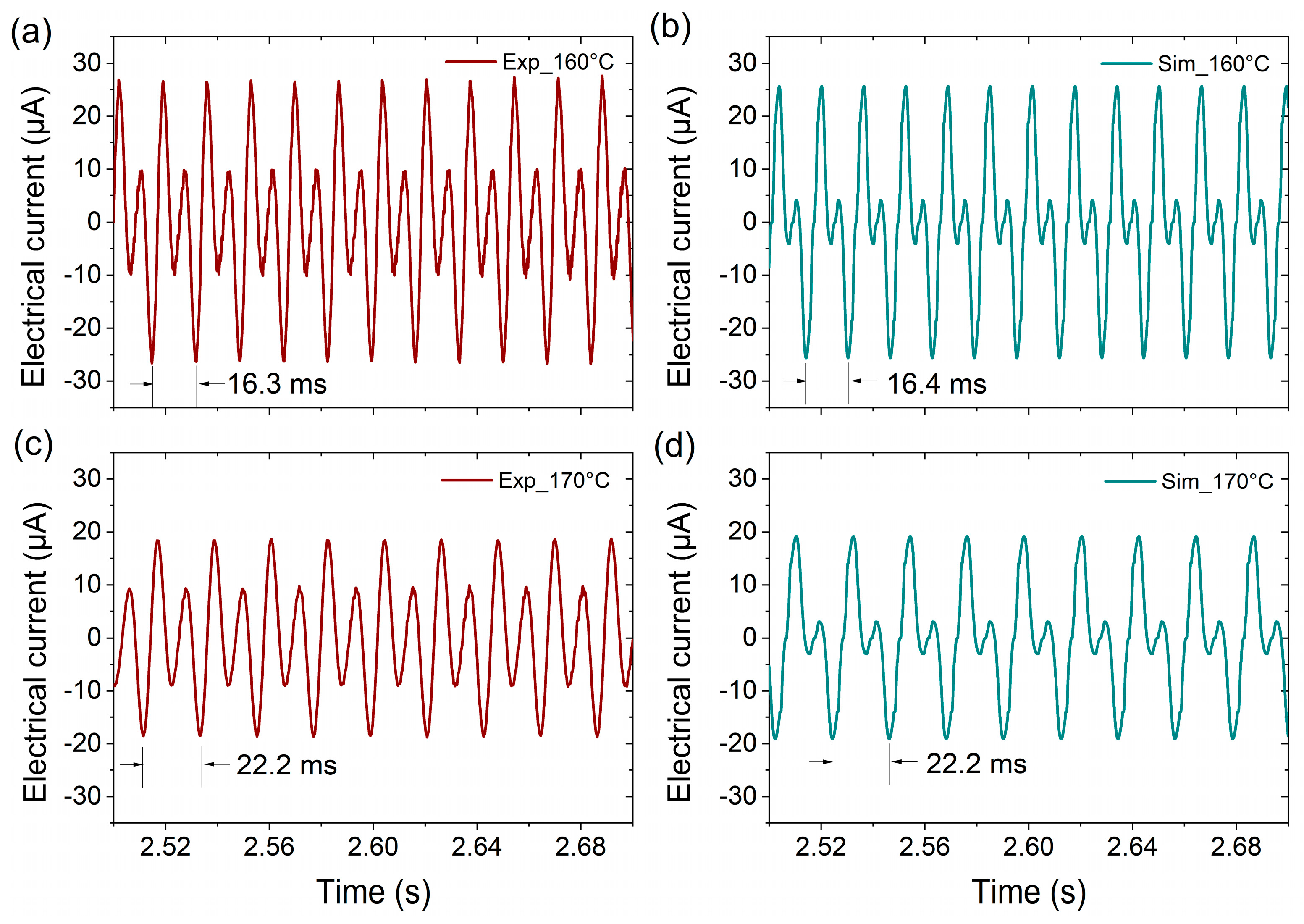
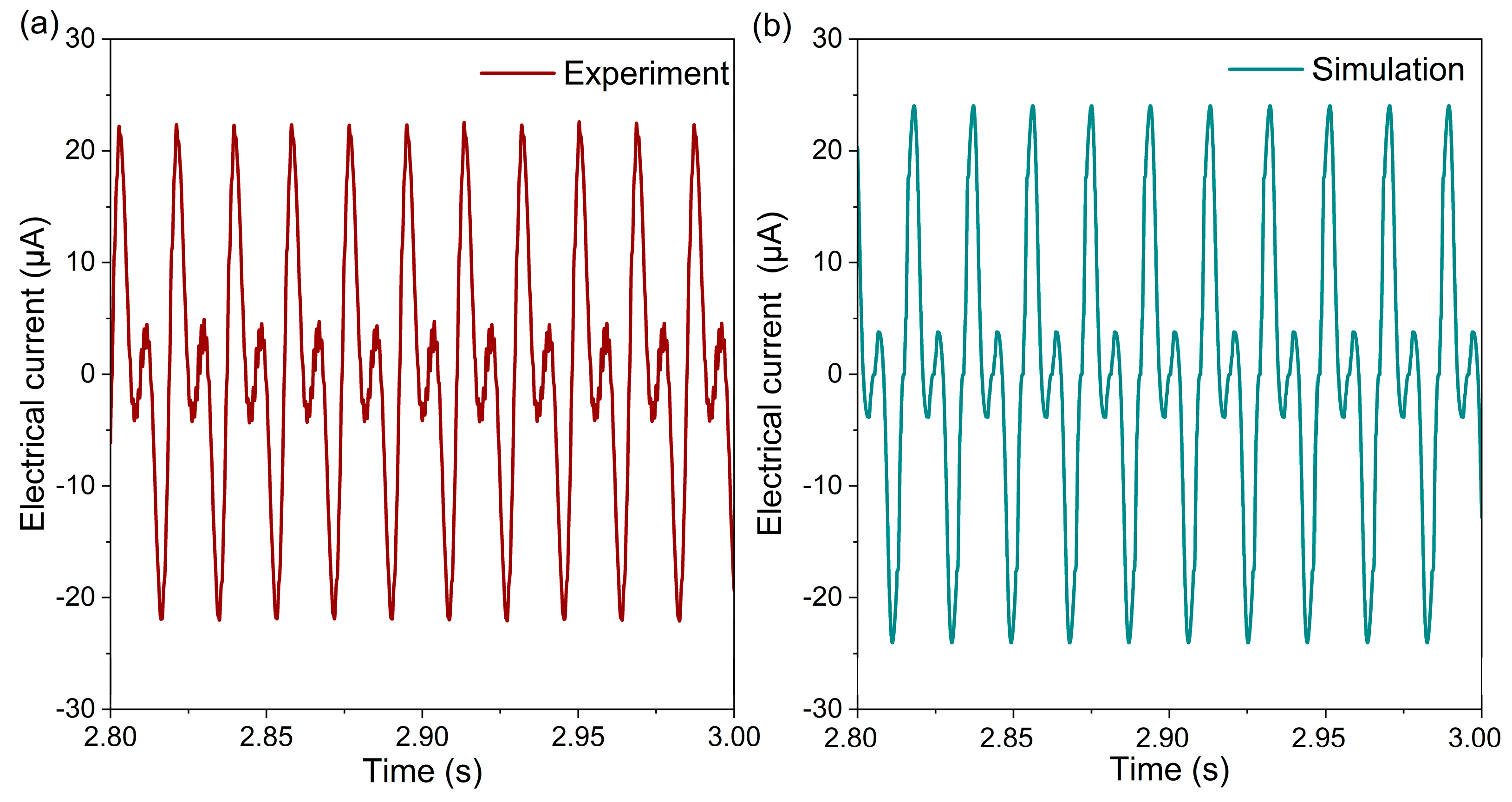
Figure 7a,b show experimental and simulated electrical performance characteristics of the bistable thermal energy harvester, respectively, for a heat-source temperature of 150 °C. The output current is determined by connecting the two pick-up coils in parallel. The output occurs in pairs of large and small peaks due to the changing direction of the magnetic field gradient in the actuation center. The simulation model reproduces the current amplitude and frequency of the bistable MSMA film actuator very well. Further experimental and simulation results on the electrical current output at higher heat source temperatures of 160 and 170 °C are presented in the
Appendix A (
Figure A2), which further validate the LEM simulations. The achieved average power of a single device is 0.23 µW at a heat source temperature of 150 °C and a load resistance of 1000 Ohms, which corresponds to a power per footprint of about 2.3 µW/cm
2.
8. Conclusions
A bistable magnetic shape-memory alloy (MSMA) film actuator is presented consisting of two Ni-Mn-Ga films at the front, on either side of a freestanding cantilever located between two heatable miniature permanent magnets. By selective heating of the MSMA films, the actuator operates as a bistable switch, whereby the cantilever can be switched between two deflection states at the two magnets. Continuous heating of the permanent magnets above their Curie temperature Tc gives rise to a thermally induced oscillation between the two deflection states. We demonstrate that the cantilever oscillation can be optimized by matching the time constants of the heat transfer and mechanical oscillation to achieve resonant self-actuation. A lumped-element model (LEM) is presented to determine the coupled thermal and magneto-mechanical performance of the bistable MSMA film actuator. Using LEM simulations, we investigate the transition from bistable switching to the resonant self-actuation mode. At low MSMA film temperatures, the magnetic potential of the system is higher compared to the elastic potential, and thus, the system rests in a stable deflection state at one of the two magnets. Once the MSMA film temperatures exceed Tc during contact with the permanent magnets, the actuator starts oscillating between the heated magnets. Therefore, the average temperature of the MSMA film increases, resulting in a decrease in magnetization, and a corresponding decrease in the magnetic attraction force and in the magnetic potential energy. Under stationary conditions, the total energy of the system exhibits two energy minima separated by a small energy barrier in the actuator center, which is low enough to enable continuous oscillation. In resonant self-actuation mode, the large oscillation stroke in the order of 20% of the cantilever length and high oscillation frequency at 50–60 Hz enable thermal power generation of 2.3 µW/cm2 at a heat source temperature of 150 °C.
9. Patents
The authors hold a patent related to this work.
Author Contributions
Conceptualization, M.K.; design, M.K. and J.J.; fabrication, J.J., H.M. and M.O.; software and model validation, J.J.; investigation, J.J., H.M. and M.O.; writing—original draft preparation, J.J.; writing—review and editing, M.K. and J.J.; visualization, J.J.; supervision, project administration, and funding acquisition, M.K. All authors have read and agreed to the published version of the manuscript.
Funding
This work was funded by the German Science Foundation (DFG) through the project “Thervest II” and partly supported by the Core-to-Core Program A “Advanced Research Networks” of the Japanese Science Foundation (JSPS).
Data Availability Statement
The data that support the findings of this study are available from the corresponding authors upon reasonable request.
Acknowledgments
This work was partly carried out with the support of the Karlsruhe Nano Micro Facility (KNMFi,
www.knmf.kit.edu).
Conflicts of Interest
The authors declare no conflict of interest.
Appendix A
Appendix A.1. Simulation Parameters
Table A1.
Summary of LEM simulation parameters. The parameters depend on the MSMA material and the detailed operation conditions of the TMG device.
Table A1 also shows specific values used for LEM simulation of a TMG demonstrator device using Ni-Mn-Ga films of 10 µm thickness with a Curie temperature
Tc of 371 K.
| Parameter | TMG Device Based on a Ni-Mn-Ga Film | Reference |
|---|
| Length of each MSMA film | 2 mm | This work |
| Width of each MSMA film | 2 mm | This work |
| Thickness of each MSMA film | 10 µm | This work |
| Density of each MSMA material | 8020 kg/m3 | [35] |
| Length of the cantilever beam | 5 mm | This work |
| Width of the cantilever beam | 2 mm | This work |
| Thickness of the cantilever beam | 20 µm | This work |
| Density of cantilever material | 8500 kg/m3 | [36] |
| Length of bonding layer | 2 mm | This work |
| Width of bonding layer | 2 mm | This work |
| Thickness of bonding layer | 10 µm | This work |
| Density of bonding layer | 1250 kg/m3 | [37] |
| Young’s modulus of cantilever material (E) | 1 × 10¹¹ N/m2 | [38] |
| Contact stiffness beam-magnet (kcont) | 1 × 10⁴ N/m | This work |
| Structural damping (c) | 1.12 × 10⁻⁵ Ns/m | This work |
| Impact damping (ccont) | 0.1 Ns/m | This work |
| Thermal conductivity of MSMA material | 23.2 W/mK | [39] |
| Specific heat capacity of MSMA material | 490 J/kgK | [39] |
| Thermal conductivity of cantilever material | 109 W/mK | [40] |
| Specific heat capacity of cantilever material | 400 J/kgK | [36] |
| Thermal conductivity of bonding layer | 0.225 W/mK | [37] |
| Specific heat capacity of bonding layer | 2100 J/kgK | [37] |
| Area of thermal contact | 4 mm2 | This work |
| Max. Conductive heat transfer coefficient (Kcond) | 8400 W/m2K | This work |
| Max. Convective heat transfer coefficient (Kconv) | 120 W/m2K | This work |
| Remanent magnetic field | 1.07 T | This work |
| Number of turns of coil | 800 | This work |
| Area of coil | 1.96 × 10⁻⁶ m2 | This work |
| Electrical resistance of coil (internal resistance) | 250 | This work |
| Electrical load resistance | 400 | This work |
| Operation temperature | 423 K | This work |
Appendix A.2. Experimental Performance Characteristics
Figure A1.
Typical low-field magnetization versus temperature curve of the investigated Ni-Mn-Ga films with two different thicknesses of 5 µm (
1) and 0.4 µm (
2) M, adapted from [
41].
Figure A1.
Typical low-field magnetization versus temperature curve of the investigated Ni-Mn-Ga films with two different thicknesses of 5 µm (
1) and 0.4 µm (
2) M, adapted from [
41].
Figure A2.
Performance of the bistable thermal energy harvester for heat source temperatures of 160 and 170 °C. (a,c) experimentally determined electrical current in the pick-up coils connected in parallel, (b,d) are the corresponding LEM simulations. The simulation model reproduces the amplitude and frequency of the bistable MSMA film actuator very well, while the small peaks due to the changing direction of the magnetic field gradient are less pronounced.
Figure A3.
Experimental setup with the bistable MSMA film actuator shown in front view (a) and side view (b). It consists of a free-standing cantilever, two pick-up coils, and MSMA films 1 and 2 on both sides of the cantilever.
Figure A3.
Experimental setup with the bistable MSMA film actuator shown in front view (a) and side view (b). It consists of a free-standing cantilever, two pick-up coils, and MSMA films 1 and 2 on both sides of the cantilever.
References
- Heczko, O.; Seiner, H.; Fähler, S. Coupling between Ferromagnetic and Ferroelastic Transitions and Ordering in Heusler Alloys Produces New Multifunctionality. MRS Bull. 2022, 47, 618–627. [Google Scholar] [CrossRef]
- Ullakko, K.; Huang, J.K.; Kantner, C.; O’Handley, R.C.; Kokorin, V.V. Large Magnetic-field-induced Strains in Ni 2 MnGa Single Crystals. Appl. Phys. Lett. 1996, 69, 1966–1968. [Google Scholar] [CrossRef]
- Murray, S.J.; Marioni, M.A.; Kukla, A.M.; Robinson, J.; O’Handley, R.C.; Allen, S.M. Large Field Induced Strain in Single Crystalline Ni–Mn–Ga Ferromagnetic Shape Memory Alloy. J. Appl. Phys. 2000, 87, 5774–5776. [Google Scholar] [CrossRef]
- Sozinov, A.; Likhachev, A.A.; Lanska, N.; Ullakko, K. Giant Magnetic-Field-Induced Strain in NiMnGa Seven-Layered Martensitic Phase. Appl. Phys. Lett. 2002, 80, 1746–1748. [Google Scholar] [CrossRef]
- Kainuma, R.; Oikawa, K.; Ito, W.; Sutou, Y.; Kanomata, T.; Ishida, K. Metamagnetic Shape Memory Effect in NiMn-Based Heusler-Type Alloys. J. Mater. Chem. 2008, 18, 1837. [Google Scholar] [CrossRef]
- Kohl, M.; Reddy, Y.S.; Khelfaoui, F.; Krevet, B.; Backen, A.; Fähler, S.; Eichhorn, T.; Jakob, G.; Mecklenburg, A. Recent Progress in FSMA Microactuator Developments. Mater. Sci. Forum 2009, 635, 145–154. [Google Scholar] [CrossRef]
- Kohl, M.; Gueltig, M.; Pinneker, V.; Yin, R.; Wendler, F.; Krevet, B. Magnetic Shape Memory Microactuators. Micromachines 2014, 5, 1135–1160. [Google Scholar] [CrossRef]
- Khelfaoui, F.; Kohl, M.; Szabo, V.; Mecklenburg, A.; Schneider, R. Development of Single Crystalline Ni-Mn-Ga Foil Microactuators. In ICOMAT; John Wiley & Sons, Inc.: Hoboken, NJ, USA, 2013; pp. 215–222. [Google Scholar]
- Heczko, O.; Soroka, A.; Hannula, S.-P. Magnetic Shape Memory Effect in Thin Foils. Appl. Phys. Lett. 2008, 93, 022503. [Google Scholar] [CrossRef]
- Dong, J.W.; Chen, L.C.; Xie, J.Q.; Müller, T.A.R.; Carr, D.M.; Palmstrøm, C.J.; McKernan, S.; Pan, Q.; James, R.D. Epitaxial Growth of Ferromagnetic Ni2MnGa on GaAs(001) Using NiGa Interlayers. J. Appl. Phys. 2000, 88, 7357–7359. [Google Scholar] [CrossRef]
- Jakob, G.; Elmers, H.J. Epitaxial Films of the Magnetic Shape Memory Material. J. Magn. Magn. Mater. 2007, 310, 2779–2781. [Google Scholar] [CrossRef]
- Backen, A.; Yeduru, S.R.; Diestel, A.; Schultz, L.; Kohl, M.; Fähler, S. Epitaxial Ni-Mn-Ga Films for Magnetic Shape Memory Alloy Microactuators. Adv. Eng. Mater. 2012, 14, 696–709. [Google Scholar] [CrossRef]
- Mostafaei, A.; Rodriguez De Vecchis, P.; Stevens, E.L.; Chmielus, M. Sintering Regimes and Resulting Microstructure and Properties of Binder Jet 3D Printed Ni-Mn-Ga Magnetic Shape Memory Alloys. Acta Mater. 2018, 154, 355–364. [Google Scholar] [CrossRef]
- Kohl, M.; Krevet, B.; Yeduru, S.R.; Ezer, Y.; Sozinov, A. A Novel Foil Actuator Using the Magnetic Shape Memory Effect. Smart Mater. Struct. 2011, 20, 094009. [Google Scholar] [CrossRef]
- Kabla, M.; Ben-David, E.; Shilo, D. A Novel Shape Memory Alloy Microactuator for Large In-Plane Strokes and Forces. Smart Mater. Struct. 2016, 25, 075020. [Google Scholar] [CrossRef]
- Musiienko, D.; Saren, A.; Ullakko, K. Magnetic Shape Memory Effect in Single Crystalline Ni-Mn-Ga Foil Thinned down to 1 μm. Scr. Mater. 2017, 139, 152–154. [Google Scholar] [CrossRef]
- Musiienko, D.; Straka, L.; Klimša, L.; Saren, A.; Sozinov, A.; Heczko, O.; Ullakko, K. Giant Magnetic-Field-Induced Strain in Ni-Mn-Ga Micropillars. Scr. Mater. 2018, 150, 173–176. [Google Scholar] [CrossRef]
- Kohl, M.; Brugger, D.; Ohtsuka, M.; Takagi, T. A Novel Actuation Mechanism on the Basis of Ferromagnetic SMA Thin Films. Sens. Actuators A Phys. 2004, 114, 445–450. [Google Scholar] [CrossRef]
- Kainuma, R.; Imano, Y.; Ito, W.; Sutou, Y.; Morito, H.; Okamoto, S.; Kitakami, O.; Oikawa, K.; Fujita, A.; Kanomata, T.; et al. Magnetic-Field-Induced Shape Recovery by Reverse Phase Transformation. Nature 2006, 439, 957–960. [Google Scholar] [CrossRef] [PubMed]
- Srivastava, V.; Chen, X.; James, R.D. Hysteresis and Unusual Magnetic Properties in the Singular Heusler Alloy Ni45Co5Mn40Sn10. Appl. Phys. Lett. 2010, 97, 014101. [Google Scholar] [CrossRef]
- Srivastava, V.; Song, Y.; Bhatti, K.; James, R.D. The Direct Conversion of Heat to Electricity Using Multiferroic Alloys. Adv. Energy Mater. 2011, 1, 97–104. [Google Scholar] [CrossRef]
- Post, A.; Knight, C.; Kisi, E. Thermomagnetic Energy Harvesting with First Order Phase Change Materials. J. Appl. Phys. 2013, 114, 033915. [Google Scholar] [CrossRef]
- Gueltig, M.; Ossmer, H.; Ohtsuka, M.; Miki, H.; Tsuchiya, K.; Takagi, T.; Kohl, M. High Frequency Thermal Energy Harvesting Using Magnetic Shape Memory Films. Adv. Energy Mater. 2014, 4, 1400751. [Google Scholar] [CrossRef]
- Gueltig, M.; Wendler, F.; Ossmer, H.; Ohtsuka, M.; Miki, H.; Takagi, T.; Kohl, M. High-Performance Thermomagnetic Generators Based on Heusler Alloy Films. Adv. Energy Mater. 2017, 7, 1601879. [Google Scholar] [CrossRef]
- Joseph, J.; Ohtsuka, M.; Miki, H.; Kohl, M. Upscaling of Thermomagnetic Generators Based on Heusler Alloy Films. Joule 2020, 4, 2718–2732. [Google Scholar] [CrossRef]
- Ohtsuka, M.; Itagaki, K. Effect of Heat Treatment on Properties of Ni-Mn-Ga Films Prepared by a Sputtering Method. Int. J. Appl. Electromagn. Mech. 2001, 12, 49–59. [Google Scholar] [CrossRef]
- Castaño, F.J.; Nelson-Cheeseman, B.; O’Handley, R.C.; Ross, C.A.; Redondo, C.; Castaño, F. Structure and Thermomagnetic Properties of Polycrystalline Ni–Mn–Ga Thin Films. J. Appl. Phys. 2003, 93, 8492–8494. [Google Scholar] [CrossRef]
- Hakola, A.; Heczko, O.; Jaakkola, A.; Kajava, T.; Ullakko, K. Ni–Mn–Ga Films on Si, GaAs and Ni–Mn–Ga Single Crystals by Pulsed Laser Deposition. Appl. Surf. Sci. 2004, 238, 155–158. [Google Scholar] [CrossRef]
- Backen, A.; Yeduru, S.R.; Kohl, M.; Baunack, S.; Diestel, A.; Holzapfel, B.; Schultz, L.; Fähler, S. Comparing Properties of Substrate-Constrained and Freestanding Epitaxial Ni–Mn–Ga Films. Acta Mater. 2010, 58, 3415–3421. [Google Scholar] [CrossRef]
- Suzuki, M.; Ohtsuka, M.; Suzuki, T.; Matsumoto, M.; Miki, H. Fabrication and Characterization of Sputtered Ni2MnGa Thin Films. Mater. Trans. JIM 1999, 40, 1174–1177. [Google Scholar] [CrossRef]
- Camacho, J.M.; Sosa, V. Alternative Method to Calculate the Magnetic Field of Permanent Magnets with Azimuthal Symmetry. Rev. Mex. Fis. E 2013, 59, 8–17. [Google Scholar]
- Schütze, T. AN2008-03: Thermal Equivalent Circuit Models. Application Note. V1.0; Infineon Technologies AG: Neubiberg, Germany, 2008. [Google Scholar]
- Joseph, J.; Ohtsuka, M.; Miki, H.; Kohl, M. Thermal Processes of Miniature Thermomagnetic Generators in Resonant Self-Actuation Mode. iScience 2022, 25, 104569. [Google Scholar] [CrossRef]
- Joseph, J.; Ohtsuka, M.; Miki, H.; Kohl, M. Lumped Element Model for Thermomagnetic Generators Based on Magnetic SMA Films. Materials 2021, 14, 1234. [Google Scholar] [CrossRef] [PubMed]
- Tickle, R.; James, R.D. Magnetic and Magnetomechanical Properties of Ni2MnGa. J. Magn. Magn. Mater. 1999, 195, 627–638. [Google Scholar] [CrossRef]
- Beiss, P. Non-Ferrous Materials. In Powder Metallurgy Data; Beiss, P., Ruthardt, R., Warlimont, H., Eds.; Landolt-Börnstein—Group VIII Advanced Materials and Technologies; Springer: Berlin/Heidelberg, Germany, 2002; Volume 2A2, pp. 194–204. ISBN 3-540-42961-1. [Google Scholar]
- Assmus, W.; Brühne, S.; Charra, F.; Chiarotti, G.; Fischer, C.; Fuchs, G.; Goodwin, F.; Gota-Goldman, S.; Guruswamy, S.; Gurzadyan, G.; et al. Springer Handbook of Condensed Matter and Materials Data; Martienssen, W., Warlimont, H., Eds.; Springer: Berlin/Heidelberg, Germany, 2005; ISBN 978-3-540-44376-6. [Google Scholar]
- Gere, J.M.; Timoshenko, S. Mechanics of Materials, 4th ed.; PWS: Boston, MA, USA, 1997; ISBN 9780534934293. [Google Scholar]
- Söderberg, O.; Aaltio, I.; Ge, Y.; Heczko, O.; Hannula, S.P. Ni-Mn-Ga Multifunctional Compounds. Mater. Sci. Eng. A 2008, 481–482, 80–85. [Google Scholar] [CrossRef]
- Young, H.; Freedman, R.A. Sears and Zemansky’s University Physics with Modern Physics, 14th ed.; Pearson Education Limited: Harlow, UK, 2016; ISBN 978-1-292-10032-6. [Google Scholar]
- Chernenko, V.A.; Ohtsuka, M.; Kohl, M.; Khovailo, V.V.; Takagi, T. Transformation Behavior of Ni-Mn-Ga Thin Films. Smart Mater. Struct. 2005, 14, S245–S252. [Google Scholar] [CrossRef]
| Disclaimer/Publisher’s Note: The statements, opinions and data contained in all publications are solely those of the individual author(s) and contributor(s) and not of MDPI and/or the editor(s). MDPI and/or the editor(s) disclaim responsibility for any injury to people or property resulting from any ideas, methods, instructions or products referred to in the content. |
© 2023 by the authors. Licensee MDPI, Basel, Switzerland. This article is an open access article distributed under the terms and conditions of the Creative Commons Attribution (CC BY) license (https://creativecommons.org/licenses/by/4.0/).
