Abstract
Satellites with cryogenic instrumentation have great potential for military, commercial, and scientific space missions due to the increased sensitivity of their sensors, even for Low Earth Orbit (LEO) missions. For these missions, magnetorquers are a common electromagnetic actuation solution for controlling the attitude and orientation of the satellite. As for any other component of a satellite, the optimization of power consumption and weight is always beneficial for the design. In this work, we propose a novel idea to reduce power consumption during magnetorquer operation: installing the magnetorquer in the cryogenic area of the satellite, instead of installing an actuator in the hot area. As the electric resistivity of the wire is greatly reduced, power consumption is also reduced. However, the heat generated in the magnetorquer, even if lower, must still be dissipated by the cryocooling system, which has an additional energetic cost. The cryogenic temperature range where this effect is beneficial, and the amount of power saved, was determined as a function of different cryocooler technologies’ efficiency and the purity of the copper wire material. It is analytically demonstrated that the operation of the magnetorquer in a temperature range from 10 to 40 K could save energy with respect to operation at 300 K if the copper wires have a residual resistance ratio larger than 200 RRR. A prototype magnetorquer suitable for cryogenic temperatures was manufactured and tested at liquid nitrogen temperature, 77 K, to experimentally demonstrate the variation in the energy consumption. The magnetorquer comprised an iron core with copper wire winding that achieved 1.42 Am2 by applying 0.565 W at 0.5 A. When operating submerged in liquid nitrogen at a temperature of 77 K, the power used by the magnetorquer was reduced by eight times due to the change in electrical resistivity.
1. Introduction
The development of spacecraft technologies in recent years has led to a reduction in the number of subsystems and loads. This reduction allows the manufacturing of lightweight satellites commonly referred to as smallsats, CubeSats, or nanosats. Some factors that have motivated the increased production of these types of satellites are the possibility of cheaper and faster qualification, lower budgets, shorter phases of development, standardization, international cooperation, purpose isolation, and the incorporation of up-to-date technologies. The main fields of application are spacecraft research and development, communications, remote sensing, military, and scientific studies [1,2]. The potential applications expand to smallsat constellations and networks [3,4].
One of the main issues in satellite orbit operation is attitude control. This involves stabilization, detumbling, and orientation with respect to Earth reference points [5,6,7,8]. Mechanical actuators with moving parts such as control moment gyroscopes [9], reaction wheels [10], or propulsion systems [11] such as chemical [12], electrical, and cold gas rockets [13] have been widely used in space missions. Nevertheless, the use of moving parts in spacecraft implies a limited lifecycle, as well as fatigue and lubrication problems at low temperatures [14]. Other solutions such as electromagnetic actuators have been explored to avoid those tribological issues in space and cryogenic applications [15,16,17,18,19,20], as well as magneto-mechanical devices such as magnetic torque limiters, gears, and bearings [21,22]; there are also studies where space contactless mechanical actuators were used to take advantage of cryogenic cooling [23]. Miniaturization of these electromagnetic systems developed for MEMS sensors and actuators is possible in space applications [24,25,26,27] and is especially important given the current aim towards smaller satellites observed in the industry.
Magnetorquers become especially relevant for the miniaturization of satellites. Magnetorquers are a type of electromagnetic actuator used for attitude control applications such as stabilization without the need for any moving parts [28,29,30]. They are cheap, easy-to-manufacture, lightweight, compact, and reliable devices [31]. Magnetorquers generate a magnetic dipolar moment (m) and take advantage of the Earth’s magnetic field (B) to drive mechanical torque in the spacecraft around the center of the generated magnetic field in one tridimensional axis. Magnetorquers are usually installed in spacecraft in a set of three in orthonormal positioning, to make omnidirectional pointing possible, while also being suitable for combination with other methods such as mechanical actuation [32]. The configuration of magnetorquers can vary from slender round-winded coils [33] to planar coreless square-winded coils [34]. Planar coils can also be made by PCB printing, making the integration with electronics easier, and occupying a very small volume [35,36]. Iron-cored slender magnetorquers are of special interest. A ferromagnetic core, when excited by an external field, can present a magnetic field inside the winding that can be up to thousands of times more dense than that in non-ferromagnetic core magnetorquers [37].
The magnetic torque transmitted to the body of the spacecraft depends on the Earth’s magnetic field. The magnetic field density and its homogeneity decrease drastically with the distance to the Earth’s surface; for this reason, magnetorquer applications are limited to Low Earth Orbit (LEO) missions. LEOs are mid-inclination circular orbits in a typical altitude range from 400 km to 700 km, above the Earth’s surface, and below the Van Allen Belt [38]. Higher altitudes can be found in LEO missions, but they are always lower than 2000 km. Some cases of special interest are Equatorial Low Earth Orbits (ELEOs), for situations requiring the lowest delta-v of any orbit, and Sun-synchronous orbits, near-polar orbits that ensure a constant illumination angle over the Earth. Some benefits of LEOs are as follows: almost the entire Earth’s surface can be covered by a single smallsat constellation; high Doppler shift permits position and tracking determination; much lower-power Earth user terminals can be achieved, and due to multiple satellite paths, signal interruption is avoided [39]. More specifically, there are promising instrumentation technologies used in LEO missions that require cryogenic temperature refrigeration, at <100 K, to work appropriately. A number of past LEO satellites with cryocooling systems are listed in Appendix A [40]; in addition, missions such as the James Webb telescope, JAXA Spica, and ESA ATHENA require a cryogenic environment. Some of these satellites include high-temperature superconductors (HTS) for levitation mechanisms [41,42,43] and superconductors for telecommunication amplifiers, Earth infrared observation instruments, or astronomy instruments [44]. The most remarkable application is cryogenic photon detectors. The main advantages of this type of sensor versus conventional ones are their much higher sensitivity and better energy resolution. Electromagnetic spectrum sensors for a wide wavelength range benefit from the use of cryogenics, but low energy detectors in the region between Near InfraRed (NIR) and Far InfraRed (FIR) see the most substantial improvements. The combination of smallsat spacecraft and LEOs that require cryogenic cooling is very likely to occur. Therefore, the idea presented and described herein is very applicable for future missions.
In this work, a novel idea to reduce power consumption during magnetorquer operation is presented. It is based on the installation of the magnetorquer or a set of them in the cryogenic area of the satellite, instead of installing the actuator at ambient temperature. As the electric resistivity of the wire is greatly reduced, power consumption is also reduced. However, the heat generated in the magnetorquer, even if lower, still must be dissipated by the cryocooling system, which has an additional energetic cost. In space systems, mass is a critical issue; this idea does not imply a mass penalty. Further, actuators often assume a significant fraction of the orbit average power (OAP); thus, if power consumption is reduced, the size of solar panels and batteries can be reduced as well. However, a risk analysis of this scenario must first be undertaken, which is beyond the scope of this work.
The cryogenic temperature range where the studied effect is beneficial, and the relative amount of power saved, was determined by considering the thermal system that extracts heat from the cooled zone and delivers to the zone at 300 K. This profitable situation of power consumption is independent of the size and the nominal power of the magnetorquer. A prototype magnetorquer, dimensioned for nanosatellites and suitable for cryogenic temperatures, was manufactured and tested at liquid nitrogen temperature, 77 K, to experimentally demonstrate this effect.
2. Theory
2.1. Magnetorquer Design and Electromagnetic FEA Model
A magnetorquer was designed, optimized, and manufactured, then characterized in a cryogenic environment.
The torque induced is described in Equation (1), where m is the magnetic moment of the magnetorquer, and B is the magnetic field in the surroundings. The magnetic moment generated by a magnetorquer depends on the configuration, size, magnetic properties of the materials, and circulating electrical current:
A ferromagnetic core magnetorquer configuration was chosen for the design, due to the high current–moment efficiency achievable as compared to other configurations. An electromagnetic 2D axisymmetric FEM model was simulated in ANSYS to optimize the design and determine its performance (see Figure 1). The simulated environment was a cylinder in vacuum that reached 150 mm on the −Z axis and 1000 mm on the +Z axis (the measuring side), with 110 mm of radial distance, and with its boundary frontier defined as ‘balloon’. The mesh was automatically generated by imposing a calculation error limit of 0.01% and a triangular cell shape. After 5 steps of calculation, the model contained about 118,067 elements. The magnetostatic field solver verified Maxwell equations, considering the magnetic permeability of materials [45]:
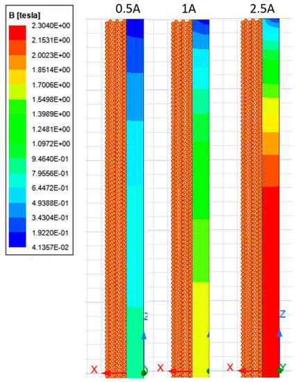
Figure 1.
Magnetization level of the ferromagnetic core at different current values.
The model was optimized to obtain the best relative performance; the moment–current, moment–weight, and moment–power ratios were considered. The magnetic field density that the magnetorquer generates can be calculated using two different equations: Equation (5), which represents the field generated by a uniformly magnetized cylinder core [37], and Equation (6), which is the magnetic dipole approximation. In both expressions, z is the distance to the center of the core on the axis of symmetry, L is the length of the dipole, Bz is the magnetic field density along the axis of symmetry, and m is the magnetic moment.
With the simulated Bz values along the axis, the magnetic moments obtained by both approximations in Equations (5) and (6) can be plotted. Both expressions tend to have a convergent value for an infinite axial distance. Then, a measuring distance can be established to calculate the magnetic moment using either of the expressions for a maximum difference between both approximations. This distance depends on the geometry and the size of the core but not on the current applied. A representative distance to measure the Bz field, where the magnetic moment calculation of both expressions converges, is z = 0.75 m, with variation less than 1% of the average of the calculations:
Any iron-core magnetorquer will generate a magnetic moment proportional to the applied current until the ferromagnetic material reaches its magnetic saturation. The materials selected for the prototype were Vacoflux50, a high-quality ferromagnetic material, and a 0.5 mm enameled copper wire with a residual resistance ratio (RRR) of 200. The wire diameter selection was made considering a tradeoff between voltage and current. Thin wire implies a very low current but too high a voltage, whereas too thick a wire implies too high a current and a lower filling factor. Vacoflux50 is a FeCo-2V alloy that presents a relative permeability of 15,000 and a magnetic saturation limit between 2.3 and 2.5 T. These characteristics represent nearly the best quality among the ferromagnetic alloys available on the market to obtain the maximum magnetic field levels inside the core. In Figure 1, the process of magnetic saturation inside the core of the optimal design is shown. The core starts saturating from the center at first, and then the saturated area increases. From this point, applying a larger amount of current does not result in an increased magnetic field density inside the core; hence, no more significant magnetic moment is obtained.
Firstly, a bulk copper cylinder was assumed as the conductor section during the optimization process because its magnetic field contribution is the same. By applying orthogonal optimization to its specific performance characteristics, the external radius, core radius, and current density were established. The geometric and magnetic parameters of the proposed magnetorquer are listed in Table 1. Figure 2 shows the magnetic moment calculated from the simulated magnetic field density, generated as the current increases. A linear dependence is clearly visible until around 1 A of supply current. For this magnetorquer size, no more than 5 W power supply modules are needed due to the magnetic saturation, as represented in Figure 3. An optimal operation point at 0.5 A, 1.42 Am2, and 0.566 W was selected.

Table 1.
Optimal magnetorquer design and performance.
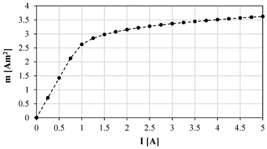
Figure 2.
Calculated magnetic dipole moment versus current applied.
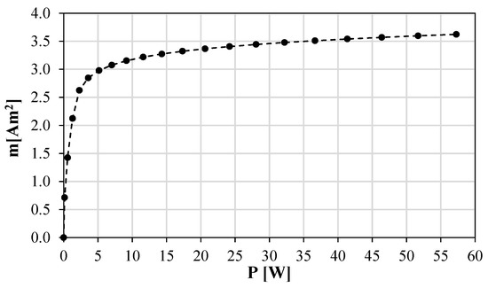
Figure 3.
Calculated magnetic dipole moment versus power consumed.
This design shows better performance in terms of magnetic moment generation and the relative ratio of the efficiency and specific moment than the state-of-the-art alternatives. In Table 2, some previous commercial and research magnetorquers of similar sizes are compared to the magnetorquer manufactured in this work. As far as we are aware, none of them have ever been tested.
Table 2.
Comparison between the proposed magnetorquer and the state-of-the-art.
The designed FEA electromagnetic model was manufactured to demonstrate its behavior at cryogenic temperatures. The ferromagnetic core was machined from a 100 mm long and 5 mm diameter cylinder made of 2VFeCo magnetic alloy (Vacoflux50). Two small axial blind holes were made in the extremes of the core to fit aluminum stoppers. These stoppers allowed the correct axial alignment of a magnetic field density probe during testing. The winding process was performed in a low-speed lathe, with 180 turns per layer for a total of 6 layers. The wire used was the same as that in the FEM model (a 0.5 mm enameled copper wire with 200 RRR). The final manufactured prototype is shown in Figure 4. The series connection between layers ensured a homogeneous current through all the layers.
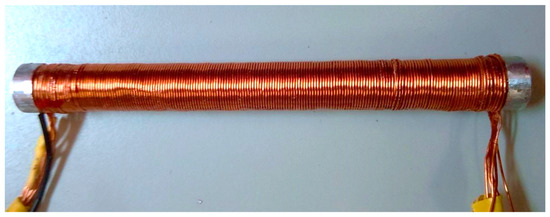
Figure 4.
Manufactured magnetorquer prototype.
2.2. Thermal Behavior of a Magnetorquer in Cryogenics and Cryocooling Systems
In some satellites, precision sensors such as cryogenic photon detectors are installed in a cryogenic area, while the rest of the subsystems work at 300 K (hot point). The temperature inside the cooled chamber varies depending on the cryocooling system, but it commonly ranges from 1 K to 100 K. A cryogenic cooler is a machine similar to a conventional refrigerator designed to operate at cryogenic temperatures. There are many different cooling technologies suitable for different operation temperature ranges. The main applied technologies are Adiabatic Demagnetization Refrigerators (ADRs), NIS chips, dilution coolers, cryostats, sorption pump coolers, turbo Brayton coolers, Stirling coolers, pulse tube coolers, Peltier cells, and both deep space and Earth orbit radiators [44]. The operation temperature and heat dissipation capacity of different types of space cryocoolers vary from 0.001 to 300 K, and their cooling power ranges from 1 × 10⁻¹² W to 1 × 10⁴ W [44].
Different types of cryocoolers have been used in space missions, and their efficiencies at different temperatures are described in reference [51]. The Carnot efficiency of different types of cryocoolers varies between 1% and 20%. The minimum Carnot efficiency at each temperature was considered to demonstrate that energy savings independent of the type of cryocooler are possible; the considered values are depicted in Figure 5.
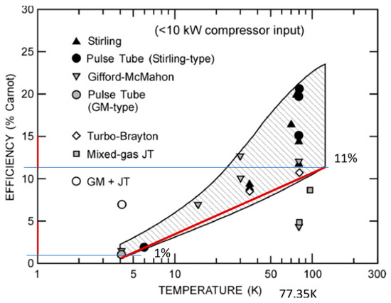
Figure 5.
Carnot efficiency of cryocoolers at different temperatures [51].
The relation between heat and power in an ideal electric cryocooler is expressed in Equation (7): the total heat expelled by the cryocooler to the 300 K hot point () is the sum of the heat extracted from the cold point () and the energy applied by the cryocooler compressor ():
If the magnetorquer is placed in the cryogenic area, then the total power required by the system is the sum of the cryocooler power (required by the magnetorquer as thermal load) and the magnetorquer consumption operating at cryogenic temperature, as expressed in Equation (8). This total power required in the cryogenic area () must be less than the power required by the magnetorquer when placed in the hot temperature area to obtain an energetic profit (Equation (9)). The chosen hot temperature was 300 K, where magnetorquers normally work alongside other systems:
The heat power generated by the magnetorquer is caused by the Joule effect on the electrical wires according to Equation (10). The electrical resistivity of the copper wires highly depends on the temperature, and so does power. The dependence of resistivity and temperature for several RRR copper quality grades has been well studied before; Figure 6 shows the curves of values previously measured [52]. It was shown that electrical resistivity can be reduced by 3 orders of magnitude compared to its value at 300 K for high-quality copper at very low temperatures. The decrease in the electrical resistance of the conductor results in a better magnetic moment-to-power ratio and, therefore, a reduction in the power required to achieve a similar level of current and magnetic moment:
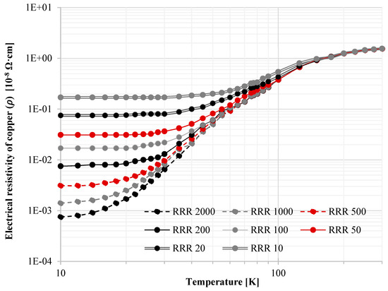
Figure 6.
Electrical resistivity of copper vs. temperature for different RRR copper quality.
For the same level of magnetic moment (and, thus, current), the ratio between the required power levels is directly the same as the ratio of electrical resistivity values, as shown in Equation (11); this is independent of the current:
The maximum coefficient of performance (COP) of a cryocooler is the ratio of ideal useful cooling provided to the required work of the compressor. For this case, it correlates with the compressor power () required to extract all the extra heat generated by the magnetorquer operating at a certain cryogenic temperature:
The real final power consumption of the cryocooler is defined as the percentage of this maximum COP with respect to the real COP, the Carnot efficiency ). Therefore, the total power consumption when operating in cryogenics () is:
The threshold point of power saving by cryocooling depends on the ebullition temperature of the refrigerant, the RRR purity level of the copper used in the magnetorquer, and the Carnot efficiency of the cryocooler. In addition, the power dissipation capacity of the cryocooler must cover the heat dissipation requirements, not only for the magnetorquer but also for the other instrumentation payloads.
3. Experimental Procedure: Room and Cryogenic Temperature Testing
The prototype was tested at room temperature (293 K) and at a temperature of 77 K to measure its magnetic moment and energy consumption in a cryogenic environment. The prototype and the magnetic field probe were attached to an aluminum optic precision board with aluminum brackets and non-magnetic screws. This avoided any magnetic contamination of the probe. The whole setup was performed at room temperature, and the alignment of the probe and the magnetorquer is shown in Figure 7. The distance between end of the magnetorquer and probe was just 5 mm in the room temperature tests.
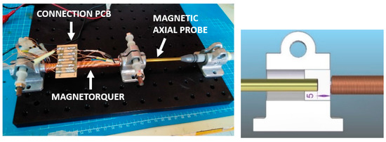
Figure 7.
Measurement setup at room temperature.
For the cryogenic tests, a container made of polystyrene as a thermal isolation material was prepared for the prototype. A 3D-printed bracket fixed the axial probe, ensuring the correct alignment between the magnetorquer axis and the probe axis. In addition, the probe was kept far from the coolant to not alter the probe sensitivity. The distance between the probe and magnetorquer was 56 mm, so the magnetic field was smaller than that in the room temperature tests. The cryogenic setup is shown in Figure 8. The cryogenic measurements are made while the prototype was submerged in liquid nitrogen at 77 K (nitrogen’s boiling point).
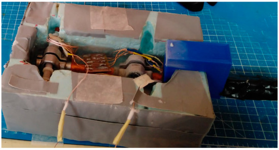
Figure 8.
Measurement setup in a cryogenic environment (77 K).
A voltage supply with current measurement (EX355P-USB from AIM-TTI INSTRUMENTS) was used to determine the electric variables. An axial magnetic field Hall-effect sensor (GM08 from Hirst Magnetics) was used to measure the axial magnetic field density.
For both setups, the current, the power, and the magnetic field density, B, were measured. Then, these magnetic field measurements were compared with the FEM model simulated magnetic field to validate the FEM model. Once this FEM model was validated, we obtained the magnetic moment by using the simulated magnetic fields and by applying Equations (5) and (6) for distances around 750 mm, which ensured that the dipole moment approximation was valid.
4. Results
Figure 9 presents a comparison between measurements of the prototype at 300 K and at 77 K. The process of saturation is visible in the graph, where the slope decreases as the input power increases. This means that less magnetic field and, hence, less magnetic moment is obtained for each additional current unit supplied.
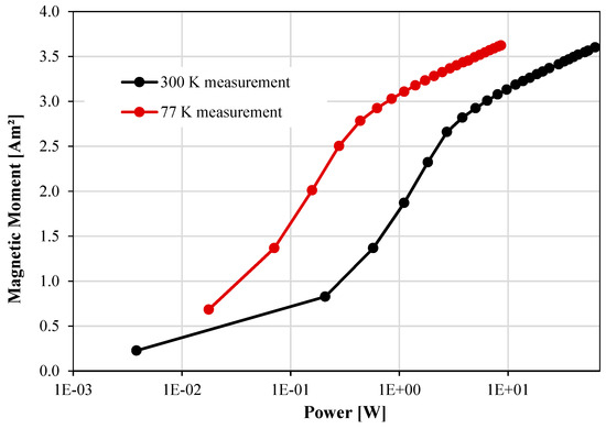
Figure 9.
Magnetorquer measurements at 300 K and at 77 K.
By submerging the proposed magnetorquer of 200 RRR copper wire in liquid nitrogen, the same level of magnetic moment was obtained with eight times less electric power consumption. The prototype achieved 3 Am2 at 300 K with an input power of 6.4 W, while at 77 K, it used 0.8 W to generate the same magnetic moment. This validated the power reduction calculations in the previous section.
5. Discussion
The proposed magnetorquer was optimized for a certain length, maximizing its specific characteristics, which means that it operates near the magnetic saturation of the core. However, if a mission requires a greater amount of magnetic moment, and the extra mass and volume are available to use, power is not a limitation if the magnetorquer is cryocooled. This is because the increment in power consumption becomes less critical with respect to the orbit average power of the spacecraft.
Figure 10 shows different power-saving scenarios depending on the copper quality and the ebullition temperature of the refrigerant. The relative power consumption is the total power at cryogenic temperatures, expressed in Equation (8), over the magnetorquer’s power consumption at room temperature. In the experimental case, the relative power consumption is 331%. This means that for the studied case, the balance of power is not profitable, consuming more than three times the nominal power at room temperature. It was demonstrated that operation of the magnetorquer in a temperature range from 10 to 40 K could save energy with respect to operation at 300 K if the copper wires have a residual resistance ratio larger than 200 RRR. For the considered Carnot efficiency values, an RRR level below 200 and operating temperatures greater than 40 K are not energetically profitable. The minimum relative power consumption reachable is 22.21% with an RRR level of 2000 at 16 K. For the RRR value of the copper used in the prototype, a 30 K operating temperature is required for the minimum power consumption of 93.3%.
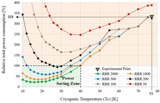
Figure 10.
Power reduction factors for several copper qualities vs. temperature.
Figure 11 presents the minimum Carnot efficiency necessary at different copper RRR levels at a certain temperature to be within the energy-saving area. For a better quality of copper, and a lower temperature, a lower cryocooler performance is acceptable.
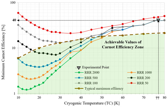
Figure 11.
Minimum Carnot efficiency of the cryocooler for various RRR levels at different temperatures.
A value of 40% Carnot efficiency is needed to satisfy the power balance for an RRR level of at least 200 at 77 K. The typical Carnot efficiency of cryocoolers at 20–30 K is between about 5 and 10%; this means that profitable scenarios are possible with commercial cryocoolers for magnetorquers using copper with an RRR of at least 200 at the minimum relative power consumption operation temperature.
6. Conclusions
Different scenarios of power saving were presented, considering parameters such as the copper wire quality, Carnot efficiency of the cryocooler used, and operating temperature at the cold point. The relative power consumption and the minimum Carnot efficiency were calculated in all scenarios.
It was analytically demonstrated that operation of the magnetorquer in the temperature range from 10 K to 40 K could save energy with respect to operation at 300 K if the copper wires have a residual resistance ratio larger than 200 RRR.
At 28 K, which is a reachable temperature for commercial cryocoolers, the required Carnot efficiency for the prototype is 7.07%. As the RRR value increases, the needed performance of the cryocoolers can be relaxed at low temperatures. The minimum relative power consumption reachable is 22.21% with an RRR of 2000 at 16 K. For the RRR value of the copper used in the prototype, a 30 K operation temperature is needed for the minimum power consumption of 93.3%.
An experimental setup with a prototype magnetorquer was manufactured to validate the calculations and the performance operation point. The manufactured prototype was a 100 mm long iron-core magnetorquer made of Vacoflux50 with 200 RRR enameled copper wire. The performance parameters of the prototype were 0.565 W, 0.5 A, and 1.42 Am2.
By cooling down to 77 K, the electric power consumption of the prototype was reduced to 1/8 of the power consumption at 300 K. The relative total power consumption was 331%. The power balance in the experimental case did not show power savings but did validate the thermal calculations and the electromagnetic FEM model. By reducing the operating temperature, the required Carnot efficiency for a power-saving situation is reduced. The cryocooler performance data used herein support the assertion that a profitable energetic balance is possible with commercially available cryocoolers.
Author Contributions
Conceptualization, G.V.-A. and E.D.-J.; Methodology, G.V.-A. and D.L.-P.; Validation, G.V.-A., I.V.-B. and D.L.-P.; Investigation, G.V.-A.; Resources, I.V.-B.; Writing—Original Draft Preparation, G.V.-A.; Writing—Review and Editing, D.L.-P.; Supervision, E.D.-J.; Project Administration, E.D.-J. All authors have read and agreed to the published version of the manuscript.
Funding
This research received no external funding.
Data Availability Statement
Data sharing not applicable. All generated data is contained within the present article.
Conflicts of Interest
The authors declare no conflict of interest.
Appendix A
Table A1.
Summary of cryogenic space programs in LEO [40].
Table A1.
Summary of cryogenic space programs in LEO [40].
| Mission | Application | Type/Class | Launch Year | Cryogenic System | In-Flight Temp. (k) | Lifetime |
|---|---|---|---|---|---|---|
| ERS (ESA)-1/2 | Earth observation | P/L (ATSR) | 1991/1995 | Stirling cooler | 80 | 2 y |
| CRISTA (DARA, D) | Earth observation | P/L (STS-66/85) | 1994/197 | 4He cryostat | 2.5–12 | 10 d |
| SFU (ISAS/NASDA/MITI) | Science (IR) | Instrument (IRST) | 1995 | 4He cryostat + 3He SC | 0.3 | 30 d |
| MSX (BMDO, US) | MP/UV to FIR | Satellite (observat.) | 1996 | sH2 cryostat | <8 | 600 d |
| BETSCE (NASA) | Technology | P/L (STS-77) | 1996 | H2 Stirling + JT + Sorpt. | 10 | <1 d |
| CheX (NASA) | Tech./MS | P/L (STS-87) | 1997 | 4He cryostat | 1.6 | >6 d |
| HST (NASA) | Science (NIR) | Nicmos, instrument | 1997 | sN2 cryostat | 60 | 700 d |
| WIRE (NASA) | Science (IR) | Satellite (surveyor) | 1999 | Dual, sH2 cryostat | <7.5 | 120 d |
| RHESSI (NASA) | Science (solar phys.) | Satellite (observat.) | 2002 | Stirling cooler | 85 | >5 yr |
| FACET (NASA/JPL) | Technology | P/L (STS) | 2003 | sCO2 + sNe cryostat | 19 | >6 d |
| Suzaku (ISAS, NASA) | Science (X-ray) | Satellite (observat.) | 2005 | sNe + 4He cryost. + ADR | 0.065 | 730 d |
| XEUS (ESA) | Science (X-ray) | Instrument (observat.) | 2005 | Stirling cool. + ADR | 0.05–0.3 | >10 yr |
| ISS/Bosch (ESA) | Tech./TLC | P/L(ISS) | 2005 | Mechanical cooler | 77 | >1 yr |
| Akari (ISAS) | Science (IR) | Satellite (observat.) | 2006 | 4He (λ) cryost. + cooler | 1.8 | 550 d |
References
- Wekerle, T.; Filho, J.B.P.; da Costa, L.E.V.L.; Trabasso, L.G. Status and trends of smallsats and their launch vehicles—An up-to-date review. J. Aerosp. Technol. Manag. 2017, 9, 269–286. [Google Scholar] [CrossRef]
- Lombardo, M.; Zannoni, M.; Gai, I.; Casajus, L.G.; Gramigna, E.; Manghi, R.L.; Tortora, P.; Di Tana, V.; Cotugno, B.; Simonetti, S.; et al. Design and Analysis of the Cis-Lunar Navigation for the ArgoMoon CubeSat Mission. Aerospace 2022, 9, 659. [Google Scholar] [CrossRef]
- Inamori, T.; Kawashima, R.; Saisutjarit, P.; Sako, N.; Ohsaki, H. Magnetic plasma deorbit system for nano- and micro-satellites using magnetic torquer interference with space plasma in low Earth orbit. Acta Astronaut. 2015, 112, 192–199. [Google Scholar] [CrossRef]
- Park, J.H.; Matsuzawa, S.; Inamori, T.; Jeung, I.S. Nanosatellite constellation deployment using on-board magnetic torquer interaction with space plasma. Adv. Space Res. 2018, 61, 2010–2021. [Google Scholar] [CrossRef]
- Mesch, F. Magnetic components for the attitude control of space vehicles. IEEE Trans. Magn. 1969, 5, 586–592. [Google Scholar] [CrossRef]
- Rajagopal, K.R. Design and development of a permanent magnet torquer for a gyroscope. IEEE Trans. Magn. 2001, 37, 2630–2633. [Google Scholar] [CrossRef]
- Rajagopal, K.R.; Singh, B.; Singh, B.P.; Vedachalam, N. Novel methods of temperature compensation for permanent magnet sensors and actuators. IEEE Trans. Magn. 2001, 37, 1995–1997. [Google Scholar] [CrossRef]
- Zhu, L.; Guo, J.; Gill, E. Analytical Field and Torque Analysis of a Reaction Sphere. IEEE Trans. Magn. 2018, 54, 1–11. [Google Scholar] [CrossRef]
- McChesney, C. Attitude control actuators for a simulated spacecraft. In Proceedings of the AIAA Guidance, Navigation, and Control Conference, Portland, OR, USA, 8–11 August 2011; pp. 1–25. [Google Scholar] [CrossRef]
- Bellar, A.; Mohammed, M.A.S.; Adnane, A. Minimum power consumption of the microsatellite attitude control using pyramidal reaction wheel configuration. In Proceedings of the 8th International Conference on Modelling, Identification and Control (ICMIC), Algiers, Algeria, 15–17 November 2016; Volume 2016, pp. 253–257. [Google Scholar] [CrossRef]
- NASA Smallsats: In-Space Propulsion Systems. Available online: https://www.nasa.gov/smallsat-institute/sst-soa/in-space-propulsion#_Toc114987899 (accessed on 24 March 2023).
- van Schyndel, J.; Goos, E.; Naumann, C.; Hardi, J.S.; Oschwald, M. Effects of Compounds in Liquefied Methane on Rocket Engine Operation. Aerospace 2022, 9, 698. [Google Scholar] [CrossRef]
- Silik, Y.; Yaman, U. Control of rotary inverted pendulum by using on–off type of cold gas thrusters. Actuators 2020, 9, 95. [Google Scholar] [CrossRef]
- Nyberg, E.; Cervelló, D.L.I.; Minami, I. Tribology in space robotic actuators: Experimental method for evaluation and analysis of gearboxes. Aerospace 2021, 8, 75. [Google Scholar] [CrossRef]
- Alcover-Sanchez, R.; Soria, J.M.; Pérez-Aracil, J.; Pereira, E.; Diez-Jimenez, E. Design and experimental characterization of a novel passive magnetic levitating platform. Smart Struct. Syst. 2022, 29, 499–512. [Google Scholar] [CrossRef]
- Diez-Jimenez, E.; Alén-Cordero, C.; Alcover-Sánchez, R.; Corral-Abad, E. Modelling and test of an integrated magnetic spring-eddy current damper for space applications. Actuators 2021, 10, 8. [Google Scholar] [CrossRef]
- Muñoz-Martínez, M.; Diez-Jimenez, E.; Gómez-García, M.J.; Rizzo, R.; Musolino, A. Torque and bearing reaction forces simulation of micro-magnetic gears. Appl. Comput. Electromagn. Soc. J. 2019, 34, 541–546. [Google Scholar]
- Fiorillo, F.; Santoni, F.; Ferrara, E.; Battagliere, M.L.; Bottauscio, O.; Graziani, F. Soft magnets for passive attitude stabilization of small satellites. IEEE Trans. Magn. 2010, 46, 670–673. [Google Scholar] [CrossRef]
- Serrano-Tellez, J.; Romera-Juarez, F.; González-De-María, D.; Lamensans, M.; Argelaguet-Vilaseca, H.; Pérez-Díaz, J.-L.; Sánchez-Casarrubios, J.; Díez-Jiménez, E.; Valiente-Blanco, I. Experience on a cryogenic linear mechanism based on superconducting levitation. In Proceedings of the SPIE—The International Society for Optical Engineering, Amsterdam, The Netherlands, 2 June 2012; Volume 8450. [Google Scholar] [CrossRef]
- Esnoz-Larraya, J.; Valiente-Blanco, I.; Cristache, C.; Sanchez-Garcia-Casarrubios, J.; Rodriguez-Celis, F.; Diez-Jimenez, E.; Perez-Diaz, J.L. OPTIMAGDRIVE: High performance magntic gears development for space applications. In Proceedings of the 17th European Space Mechanisms and Tribology Symposium, Hatfield, UK, 20–22 September 2017; pp. 1–5. [Google Scholar]
- Cristache, C.; Diez-Jimenez, E.; Valiente-Blanco, I.; Sanchez-Garcia-Casarrubios, J.; Perez-Diaz, J.-L. Aeronautical magnetic torque limiter for passive protection against overloads. Machines 2016, 4, 17. [Google Scholar] [CrossRef]
- Perez-Diaz, J.L.; Diez-Jimenez, E.; Valiente-Blanco, I.; Cristache, C.; Alvarez-Valenzuela, M.-A.; Sanchez-Garcia-Casarrubios, J. Contactless mechanical components: Gears, torque limiters and bearings. Machines 2014, 2, 312–324. [Google Scholar] [CrossRef]
- Perez-Diaz, J.L.; Diez-Jimenez, E.; Valiente-Blanco, I.; Cristache, C.; Alvarez-Valenzuela, M.-A.; Sanchez-Garcia-Casarrubios, J.; Ferdeghini, C.; Canepa, F.; Hornig, W.; Carbone, G.; et al. Performance of Magnetic-Superconductor Non-contact Harmonic Drive for Cryogenic space applications. Machines 2015, 3, 138–156. [Google Scholar] [CrossRef]
- Diez-Jimenez, E.; Sanchez-Montero, R.; Martinez-Muñoz, M. Towards miniaturization of magnetic gears: Torque performance assessment. Micromachines 2017, 9, 16. [Google Scholar] [CrossRef]
- Martinez-Muñoz, M.; Diez-Jimenez, E.; Villalba-Alumbreros, G.V.; Michalowski, M.; Lastra-Sedano, A. Geometrical dependence in fixtures for 2D multipole micromagnets magnetization pattering. Appl. Comput. Electromagn. Soc. J. 2019, 34, 1092–1101. [Google Scholar]
- Martinez-Muñoz, M.; DIez-Jimenez, E.; Sanchez-Montero, R.; Lopez-Espi, P.L.; Martinez-Rojas, J.A. Analysis of the geometric parameters influence in PCB fixtures for 2D multipole magnetization patterning of thin layer micro-magnets. Int. J. Appl. Electromagn. Mech. 2019, 61, 59–71. [Google Scholar] [CrossRef]
- Diez-Jimenez, E.; Valiente-Blanco, I.; Villalba-Alumbreros, G.; Fernandez-Munoz, M.; Lopez-Pascual, D.; Lastra-Sedano, A.; Moron-Alguacil, C.; Martinez-Perez, A. Multilayered Microcoils for Microactuators and Characterization of Their Operational Limits in Body-Like Environments. Trans. Mechatron. 2022, 1–6. [Google Scholar] [CrossRef]
- Misra, R.; Wisniewski, R.; Zuyev, A. Attitude Stabilization of a Satellite Having Only Electromagnetic Actuation Using Oscillating Controls. Aerospace 2022, 9, 444. [Google Scholar] [CrossRef]
- Celani, F. Quaternion versus Rotation Matrix Feedback for Spacecraft Attitude Stabilization Using Magnetorquers. Aerospace 2022, 9, 24. [Google Scholar] [CrossRef]
- Feng, G.; Zhang, C.; Zhang, H.; Li, W. Theoretical and Experimental Investigation of Geomagnetic Energy Effect for LEO Debris Deorbiting. Aerospace 2022, 9, 511. [Google Scholar] [CrossRef]
- Ivanov, D.S.; Ovchinnikov, M.Y.; Penkov, V.I.; Roldugin, D.S.; Doronin, D.M.; Ovchinnikov, A.V. Advanced numerical study of the three-axis magnetic attitude control and determination with uncertainties. Acta Astronaut. 2017, 132, 103–110. [Google Scholar] [CrossRef]
- Curatolo, A.; Bahu, A.; Modenini, D. Automatic Balancing for Satellite Simulators with Mixed Mechanical and Magnetic Actuation. Aerospace 2022, 9, 223. [Google Scholar] [CrossRef]
- Mehrjardi, M.F.; Mirshams, M. Design and manufacturing of a research magnetic torquer rod. In Proceedings of the Fourth International Conference on Experimental Mechanics, Singapore, 18–20 November 2009; Volume 7522, p. 75221W. [Google Scholar] [CrossRef]
- Cervettini, G.; Pastorelli, S.; Park, H.; Lee, D.Y.; Romano, M. Development and Experimentation of a CubeSat Magnetic Attitude Control System Testbed. IEEE Trans. Aerosp. Electron. Syst. 2021, 57, 1345–1350. [Google Scholar] [CrossRef]
- Mughal, M.R.; Ali, H.; Ali, A.; Praks, J.; Reyneri, L.M. Optimized Design and Thermal Analysis of Printed Magnetorquer for Attitude Control of Reconfigurable Nanosatellites. IEEE Trans. Aerosp. Electron. Syst. 2020, 56, 736–747. [Google Scholar] [CrossRef]
- Sorensen, N.J. Efficiency-Optimized Design of PCB-Integrated Magnetorquers for CubeSats. IEEE Trans. Aerosp. Electron. Syst. 2021, 57, 3623–3632. [Google Scholar] [CrossRef]
- Lee, J.; Ng, A.; Jobanputra, R. On determining dipole moments of a magnetic torquer rod—Experiments and discussions. Can. Aeronaut. Space J. 2002, 48, 61–67. [Google Scholar] [CrossRef]
- Allen, C.S.; Giraudo, M.; Moratto, C.; Yamaguchi, N. Spaceflight environment. In Space Safety and Human Performance; Elsevier: Amsterdam, The Netherlands, 2017; pp. 87–138. [Google Scholar]
- Ilcev, S.D. LOW Earth Orbits (LEO). In Proceedings of the 20th International Crimean Conference on Microwave and Telecommunication Technology, Sevastopol, Ukraine, 13–17 September 2010; pp. 406–408. [Google Scholar] [CrossRef]
- Collaudin, B.; Rando, N. Cryogenics in space: A review of the missions and of the technologies. Cryogenics 2000, 40, 797–819. [Google Scholar] [CrossRef]
- Diez-jimenez, E.; Perez-diaz, J.L.; Garcia-Prada, J.C. Mechanical Method for Experimental Determination of the First-Penetration Field in. IEEE Trans. Appl. Supercond. 2012, 22, 9003106. [Google Scholar] [CrossRef]
- Perez-Diaz, J.L.; Valiente-Blanco, I.; Diez-Jimenez, E.; Sanchez-Garcia-Casarrubios, J. Superconducting Non-Contact Device for Precision Positioning in Cryogenic Environments. IEEE/ASME Trans. Mechatron. 2014, 19, 598–605. [Google Scholar] [CrossRef]
- Valiente-Blanco, I.; Diez-Jimenez, E.; Sanchez-Garcia-Casarrubios, J.; Perez-Diaz, J.L. Improving Resolution and Run Outs of a Superconducting Noncontact Device for Precision Positioning. IEEE/ASME Trans. Mechatron. 2014, 20, 1992–1996. [Google Scholar] [CrossRef]
- Collaudin, B.; Gavila, E. Cryogenic Integration in Satellites. 2019. Available online: https://indico.cern.ch/event/792215/contributions/3558254/attachments/1918508/3172791/Cryogenic_integration_in_satellites_-_ThalesAleniaSpace.pdf (accessed on 25 March 2023).
- Ansoft Ansys Maxwell v15—Help Assistant. 2018. Available online: http://ansoft-maxwell.narod.ru/en/CompleteMaxwell3D_V15.pdf (accessed on 21 January 2023).
- Candini, G.P.; Piergentili, F.; Santoni, F. Designing, Manufacturing, and Testing a Self-Contained and Autonomous Nanospacecraft Attitude Control System. J. Aerosp. Eng. 2014, 27, 04014033. [Google Scholar] [CrossRef]
- Candinia, G.P.; Piergentilib, F.; Santoni, F. Miniaturized attitude control system for nanosatellites. Acta Astronaut. 2012, 81, 325–334. [Google Scholar] [CrossRef]
- CubeSatShop Cubesat NCTR-M002 Magnetic Rod. Available online: https://www.cubesatshop.com/product/nctr-m002-magnetorquer-rod/ (accessed on 23 January 2023).
- CubeSatShop Cubesat NCTR-M012 Magnetic Rod. Available online: https://www.cubesatshop.com/product/nctr-m012-magnetorquer-rod/ (accessed on 23 January 2023).
- Sputnix SX-MT Magnetic Torquers. Available online: https://satsearch.co/products/sputnix-magnetic-torquer-sx-mt (accessed on 20 January 2023).
- Radebaugh, R. Cryocoolers: The state of the art and recent developments. J. Phys. Condens. Matter 2009, 21, 164219. [Google Scholar] [CrossRef]
- Calatroni, S. Materials & Properties: Thermal & Electrical Characteristics. arXiv 2020, arXiv:2006.02842, 1–20. Available online: http://arxiv.org/abs/2006.02842 (accessed on 19 January 2023).
Disclaimer/Publisher’s Note: The statements, opinions and data contained in all publications are solely those of the individual author(s) and contributor(s) and not of MDPI and/or the editor(s). MDPI and/or the editor(s) disclaim responsibility for any injury to people or property resulting from any ideas, methods, instructions or products referred to in the content. |
© 2023 by the authors. Licensee MDPI, Basel, Switzerland. This article is an open access article distributed under the terms and conditions of the Creative Commons Attribution (CC BY) license (https://creativecommons.org/licenses/by/4.0/).