1. Introduction
The outbreak of COVID-19 has caused an unprecedented global threat to public health and the economy. Although the spread of some new variants has led to a situation of low death rates worldwide, improving the configuration of healthcare facilities to better respond to the status quo is still urgent. Moreover, when facing the challenges of unknown contagious diseases, reducing or eliminating exposure is always one of the crucial ways to maintain health. Traditional methods of exposure elimination, such as manual disinfectant spraying, are restricted by the availability of operators in terms of work time and concentration. Disinfection robotic systems available for remote control represent a practical and reasonable tool to fulfill various anti-epidemic purposes. Disinfection or sterilization robots can remain unhindered by peak hours or terrible operating conditions and carry out their duties all day long to prevent pathogenic attacks [
1].
Many researchers in automation and engineering have also actively responded to this conception. Since the onset of the pandemic, MIT and Boston Dynamics have begun to cooperate in the design of patient interaction robots in order to reduce the frontline virus exposure of healthcare personnel [
2]. The use of ultraviolet (UV) light is especially noticed because its energy is sufficient to destroy the DNA or RNA of any microorganism, and UV lights have been installed on many experimental mobile robots in an environment to be sanitized [
3]. These robots utilize annotated points of interest on the map to scan the area and automatically reach the location to perform specific disinfection tasks. However, limited by the characteristics of UV light and their operating distance, these robots can only execute on-ground tasks. In a previous study [
4], an intelligent disinfection robotic system was developed to enable robots to spray disinfectants in operating theaters or patients’ rooms, based on the results of controlled experiments and the requirements for hospital disinfection. A key feature of this research is the application of a novel
disinfection technology to sterilize bacteria and viruses in the air and on surfaces. Another noteworthy feature is that this robot is also based on a mobile platform, by which the disinfection abilities are severely curtailed in 3D space, such as on table tops, door handles, elevator buttons, and other regular locations that humans usually touch [
5,
6]. There are additional applications for disinfection robots. For example, SOMATIC is a commercial cleaning robot that can perform approximately eight hours of cleaning work each time it runs. It can even open doors and ride elevators to move around the building. The service range of this robot includes airports, casinos, office spaces, and other places such as large restrooms [
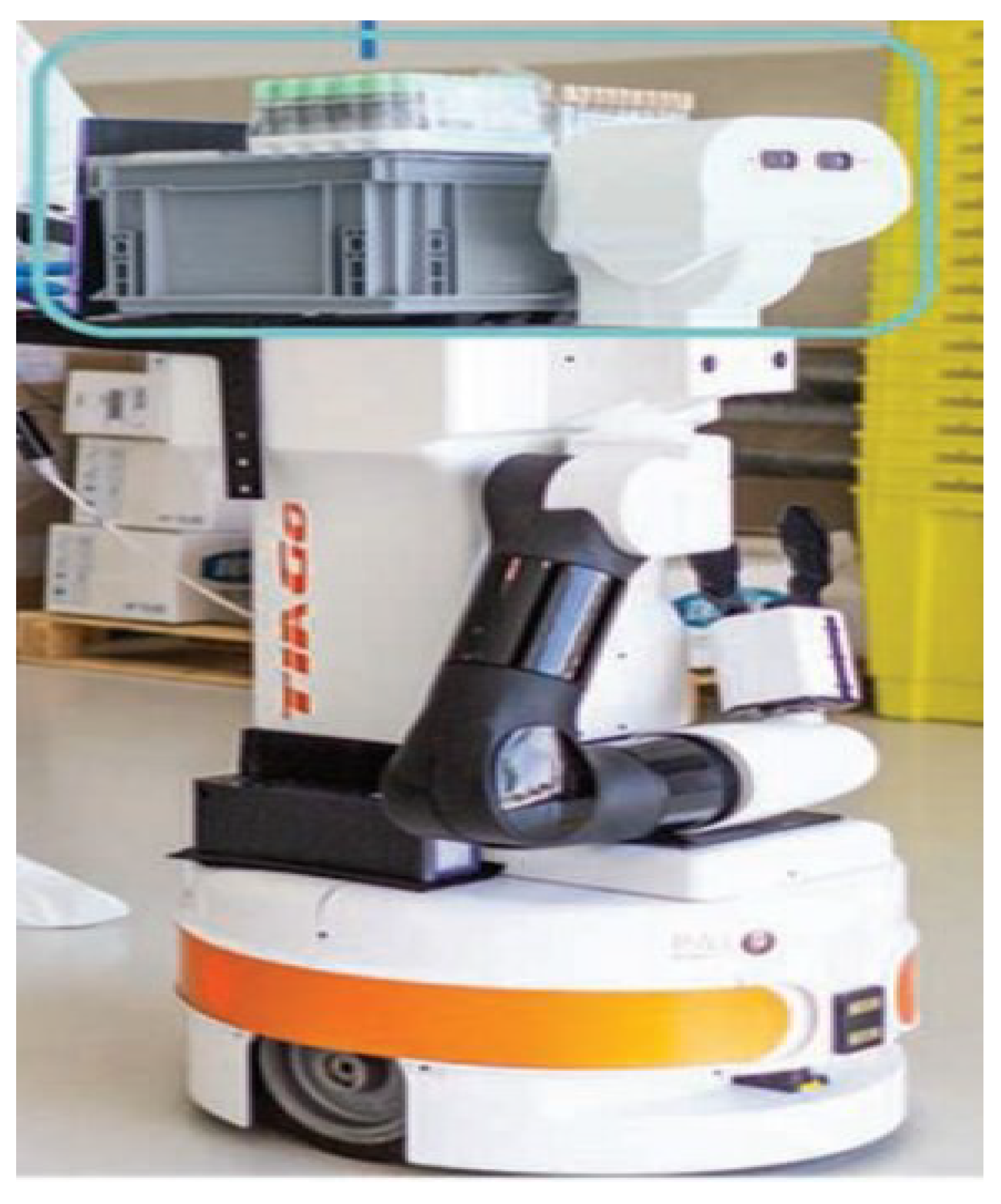
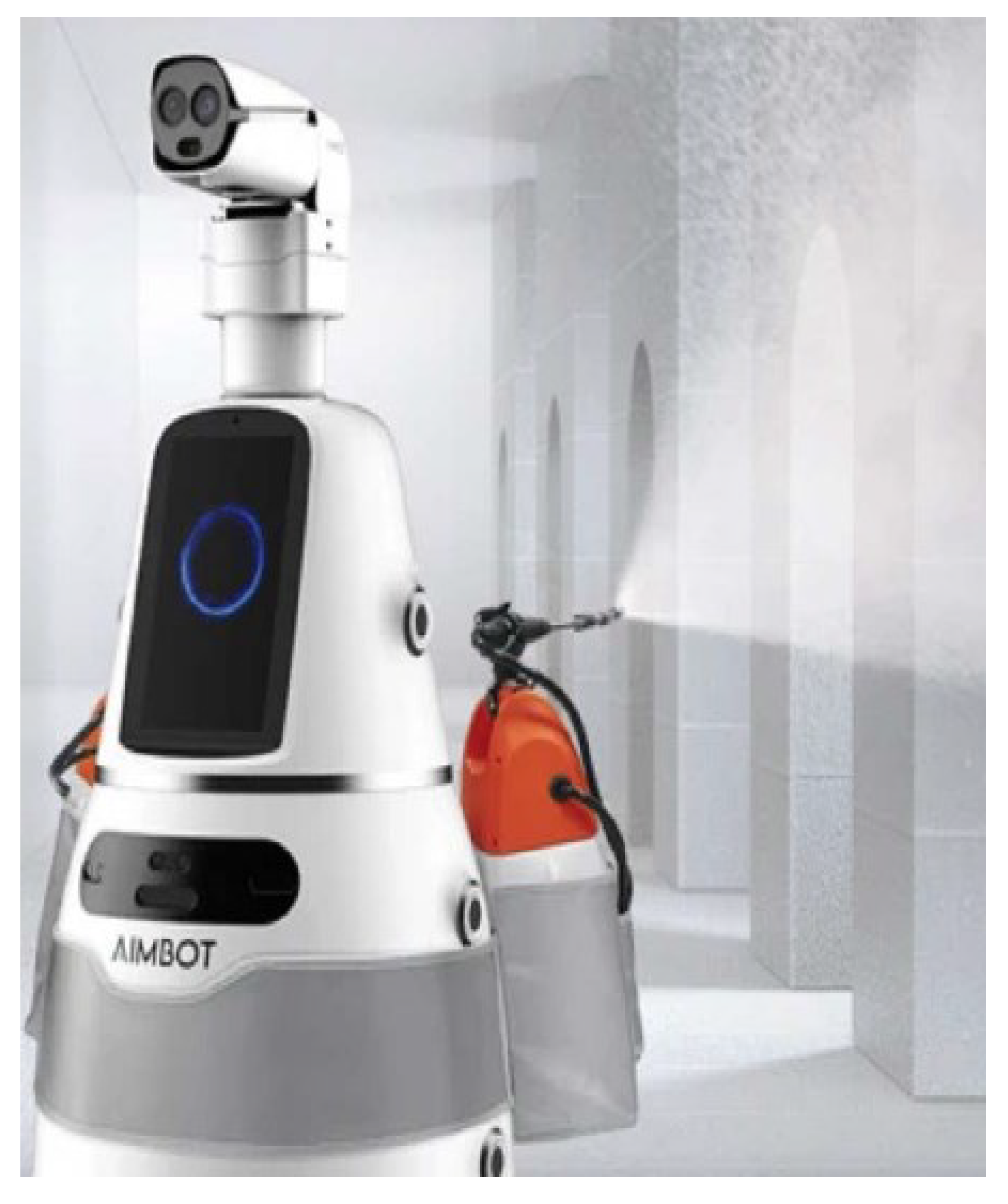
7]. The designed robot is compared with two typical disinfection robots as listed in
Table 1.
In order to better accomplish disinfection tasks, reasonable planning of the spraying path is a key element of the designed robot. We can convert this problem into a coverage path problem in 3D space. The coverage path planning (CPP) algorithm is a popular topic and has been substantially studied. It is applied for underwater or land inspection, unmanned aerial vehicles, milling, floor cleaning, painting, and medical tasks [
8]. Both offline and online CPP algorithms have been previously proposed. For example, Han [
9] proposed a complete CPP obstacle avoidance algorithm for underwater gliders in the sea, with shorter path planning and economized energy supply. Only three years have passed since the outbreak of COVID-19, so few researchers have performed in-depth studies on the disinfection path problem. Among them, Hong [
10] designed a path planning model to acquire an optimal path based on the map and the robot’s current location; however, the setting is restricted to conference rooms. Another study [
11] investigated how the robotic path can be optimized to achieve the maximum UV-irradiation performance based on environmental geometry. Bähnemann et al. presented a path planner for low-altitude terrain coverage in known environments with unmanned rotary-wing micro aerial vehicles [
12]. In this research, the algorithm was applied in conference rooms and was tested to verify the accuracy, cost, and efficiency of the robotic execution of disinfection tasks.
In line with the above studies, the objective of the present research is to design a disinfection robot that can provide effective zero-contact disinfection services for common environments in 3D space. The main characteristics of this research that differ from the existing studies are as follows.
- (1)
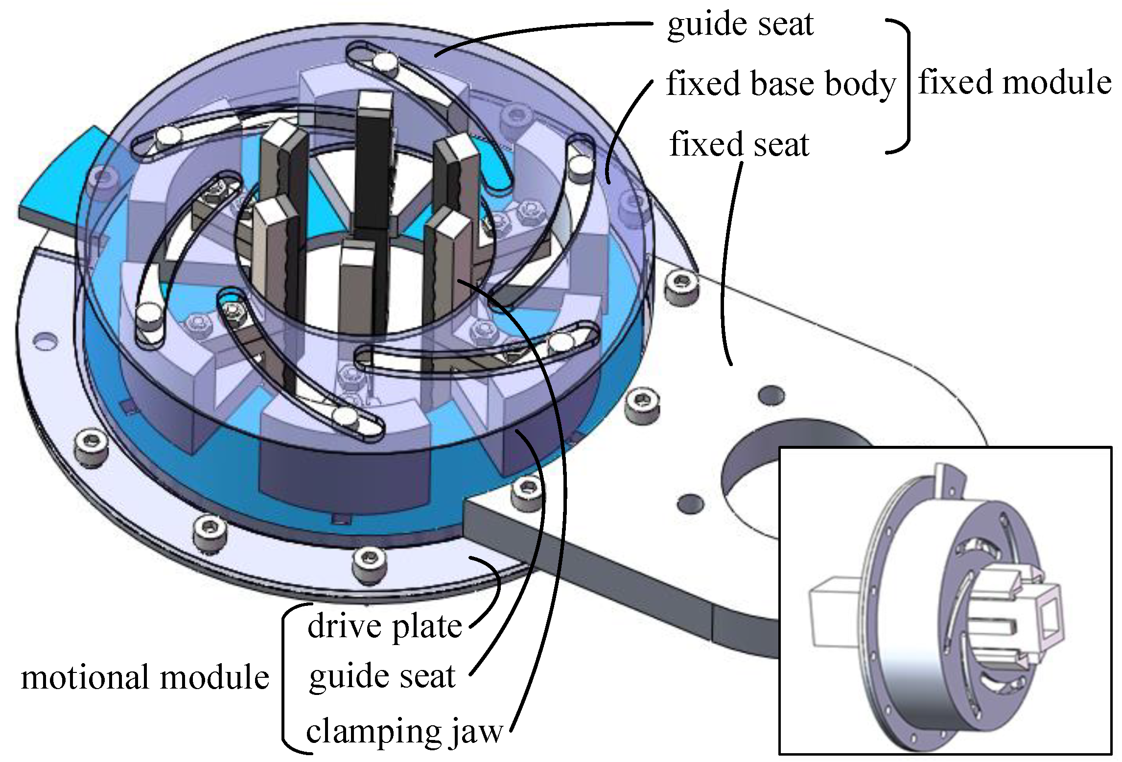
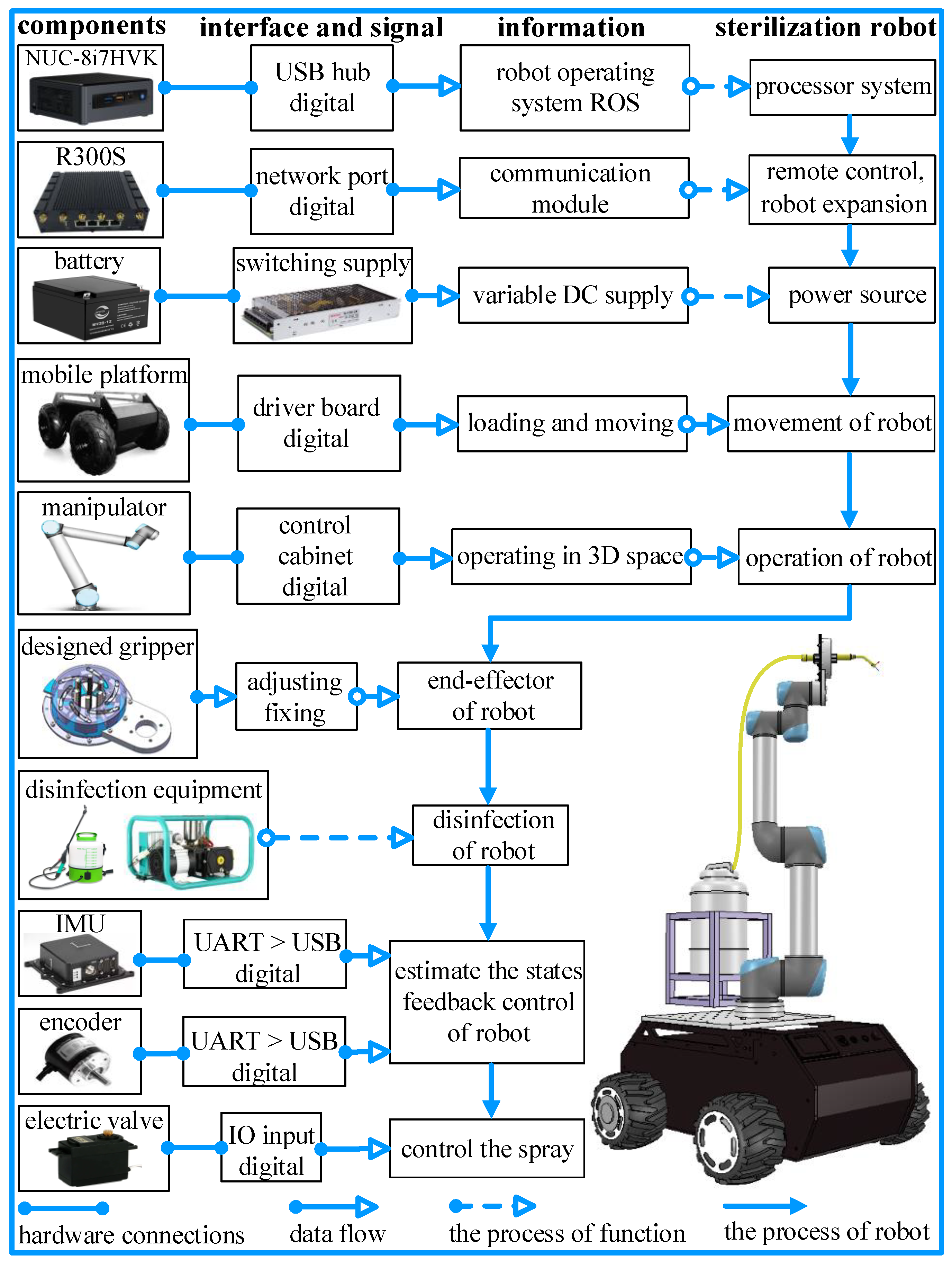
This research provides a unique design of robotic architecture from software to hardware. A key feature of our robot is that it is endowed with eight DoFs (degrees of freedom) to conduct disinfection tasks in common 3D environments based on the integration of a mobile platform, a manipulator, and the designed disinfection instrument.
- (2)
According to the characteristics of the designed robot, a CPP algorithm is used for disinfection in 3D space. In contrast to [
9] and [
11], the particularities are taken as the factors in the disinfection strategy.
- (3)
Mechanical design, multisensor data fusion, control systems, path planning, spraying disinfection, and other technologies are adopted to conduct a series of simulations and experiments to verify the performance of the robot and the proposed algorithm.
The remainder of this research is structured as follows. The second section explains the design of the disinfection robot in detail; the third section describes the proposed CPP algorithm; the fourth section verifies the performance of the robot and the proposed algorithm with two numerical examples and an experiment; and the fifth section, i.e., the conclusion, summarizes the results and outlines future work. The patents obtained based on this research are listed in the sixth section.
3. Coverage Path Planning
CPP is an important part of the robotic disinfection project. All common environmental areas should be marked and traversed, and the planned path can be obtained by connecting the nodes. Then, the robot follows this path to conduct the disinfection task, ensuring that all possible blind spots are covered with the minimal consumption of disinfectant. The scheme of the proposed CPP algorithm is shown in
Figure 4.
3.1. Space Transfer
In contrast to traditional path planning methods, each of the areas in the selected environment should be disinfected. Here, space transfer is considered, converting square pixels in 3D space into 2D arrays so that all areas are covered adequately. Each pixel (
) is regarded as an element for set
in 2D space, as shown in
Figure 3. Set
is defined as the normal vectors of each unfolded plane, and set
represents the vertices of each array in the unfolded plane. Based on set
, the set of angles between two planes is
. In practice, the initial and terminal points of the nozzle should be considered and noted as
and
.
Let
be a
homogeneous transformation matrix between the coordinate systems from point
to
. Therefore,
The geometric parameters can be obtained with defined sets.
After the above process, the CPP algorithm can be viewed as a sequence of robot configurations by which each array is visited at least once. Each array should be evaluated to determine whether or not it is basically reachable by the robot based on its kinematic capability. If the spray does not fully cover the meshed grid, one can tag the corresponding arrays as unreachable, based on which the relative pose and the path are optimized. In summary, after this step, every array will be assigned a corresponding robot configuration. Collision detection and ‘reachable’-oriented redundant configuration control are explicitly considered in the CPP algorithm. Thus, the actual coverage path may be lower than estimated in this preprocessing step.
Once the entire surface is covered, the final spray trajectory is obtained and rendered as an input to the end effector to request motion execution on the desired surface.
3.2. Coverage Path Planning
Figure 4 explains how to support the robot with the end effector to get close to the most reachable pixels in its current pose. The optimization problem of the end-effector path can be formulated as a path planning problem, the goal of which is to obtain the minimum path with the corresponding constraints and the robot configurations. After preprocessing, a path sequence (
) can be found to cover the unfolded plane (the initial and terminal points are included) within the minimum time. Based on the CPP algorithm with the rotating caliper algorithm, an unfolding plan can be introduced as
, where
is the set of vertices, and
is the set of edges. Then, the nozzle, as defined by the search pattern, follows a path to cover the area (
Q), where each point in the path will be reached by the nozzle moving in straight lines. All points in the path can be denoted as
.
Using rotating calipers, antipodal pairs
i and
j (
) are two points on the surface of a polygon that are exactly opposite each other. The idea of the method is to compute all the antipodal pairs, find the best path for each antipodal pair, and then select the path with the lowest cost in combination with the takeoff and landing points [
8]. The caliper is roated clockwise until it touches the edge then, it is rotated counter-clockwise until it touches a second edge. An
function is then defined to compute the angle swept out by a line as it rotates from its position parallels. Next, both options are measured to determine the minimum width of the formed polygon. In application, one can define vertex
i close to the initiation point. Then, the algorithm performs a sequence of decisions and procedures that do not depend on the number of vertices. Based on the antipodal pair and optimized angle, a path can be computed by the
function using a back-and-forth pattern. Finally, the plan (
S) should be folded in 3D space based on an inverse kinematic solution using Equation (
3). More details about its implementation are shown in Algorithm 1.
| Algorithm 1 Coverage path planning algorithm |
Input: normal vectors of unfolded plane ; the sizes of each unfolded plane ; plane angle ; vertices of unfold plan ; safety margin h and spray radius ; antipodal pair ; Output: waypoints in 3D space; - 1:
space transfer with using Equation ( 3); - 2:
define the rotation angle function in clockwise direction; - 3:
define the distance function between two points by using Euclidean distance formula; - 4:
define the back and forth path function based on antipodal pair and optimized angle; - 5:
if then - 6:
; ; - 7:
else - 8:
; ; - 9:
; - 10:
; ; - 11:
if then - 12:
; ; - 13:
else - 14:
; ; - 15:
if then - 16:
; - 17:
else - 18:
; - 19:
calculate the waypoints in 3D space based on inverse solution of Equation ( 3); - 20:
calculate the joint angle of mobile platform using Equation ( 1); - 21:
calculate the joint angle of manipulator in numerical iteration method with motions .
|
4. Simulation and Experiment
The application of the designed disinfection robot and the proposed CPP algorithm is verified in this section. For the disinfection test in 3D space, we assume that the spray is uniformly distributed, and the sanitizing agents are sprayed into the appointed area every second. Since pathogens can easily be found in common environments (especially on tables and door handles that are frequently touched by humans), the estimated best spraying effect can be achieved by aiming the geometric center point of the spray nozzle at least once. Two simulations and one experiment are carried out to verify the feasibility of the robot and the proposed algorithm. The first simulation focuses on the rationality and capability of path planning for key points in diverse scenarios. The second simulation aims to verify the feasibility of the robot via a disinfection task in a simulation environment. Here, the robot is aimed to disinfect a workbench in a simulation, as shown in
Figure 5. For the experiment, the scenario is identical to that in the second simulation. The experimental objective is to test the practical and theoretical performance of the robot. Corresponding videos are provided as supplementary material for this research.
4.1. Simulation and Experimental Settings
Vrep and MATLAB are used as tools for the simulations due to their close-to-physical environments and data processing abilities. The simulation process is conducted as follows. The proposed algorithm runs in MATLAB, and the implementation, and the feedback of the data are performed in Vrep with dynamic properties. First, the data and the algorithm are processed in MATLAB. Secondly, the communication for ROS nodes is established through the programming interface of the application. Then, defined outputs are continuously implemented, while the data results of the proposed algorithm are updated. Within the cosimulation with MATLAB and Vrep, the physical engine and the simulation steps are selected as Bullet (a physical engine) 2.73 and 50 ms, respectively.
For the experiment, the whole control system architecture is realized based on ROS1. A distributed multicomputer communication network for the multirobot system is adopted using the TCP/IP protocol [
14]. The ROS master runs on a remote computer (i7-8700 CPU and 8GB RAM), with which the operator can control the robot in a noninfectious environment. For the robot, an Intel NUC (i7-8559 CPU and 16GB RAM) is used as a local workstation. The control function based on the proposed CPP algorithm is integrated and executed in the local workstation. The communication between the mobile platform and the manipulator (UR5) is based on a feature package named ROS MoveIt. They can be connected using twisted pairs. The specific operations of the simulation and the experiment are shown in
Figure 5.
To better illustrate the disinfection of the robot and the proposed algorithm, the experimental area is divided into two categories: horizontal groups and vertical groups. We should also point out that a future version of the motion planner will include other parameters such as irregular regions and moving objects. The kinematic and dynamic parameters of the disinfection robot are listed in
Table 2.
The experimental process can be summarized in three steps. First, all the features of motion and path planning are packed as ROS packages. Secondly, communication tests and ROS nodes are initialized. Finally, the ROS packages of motion and path planning are executed with other necessary ROS nodes on either the local or master computers.
4.2. Validation of the CPP Algorithm
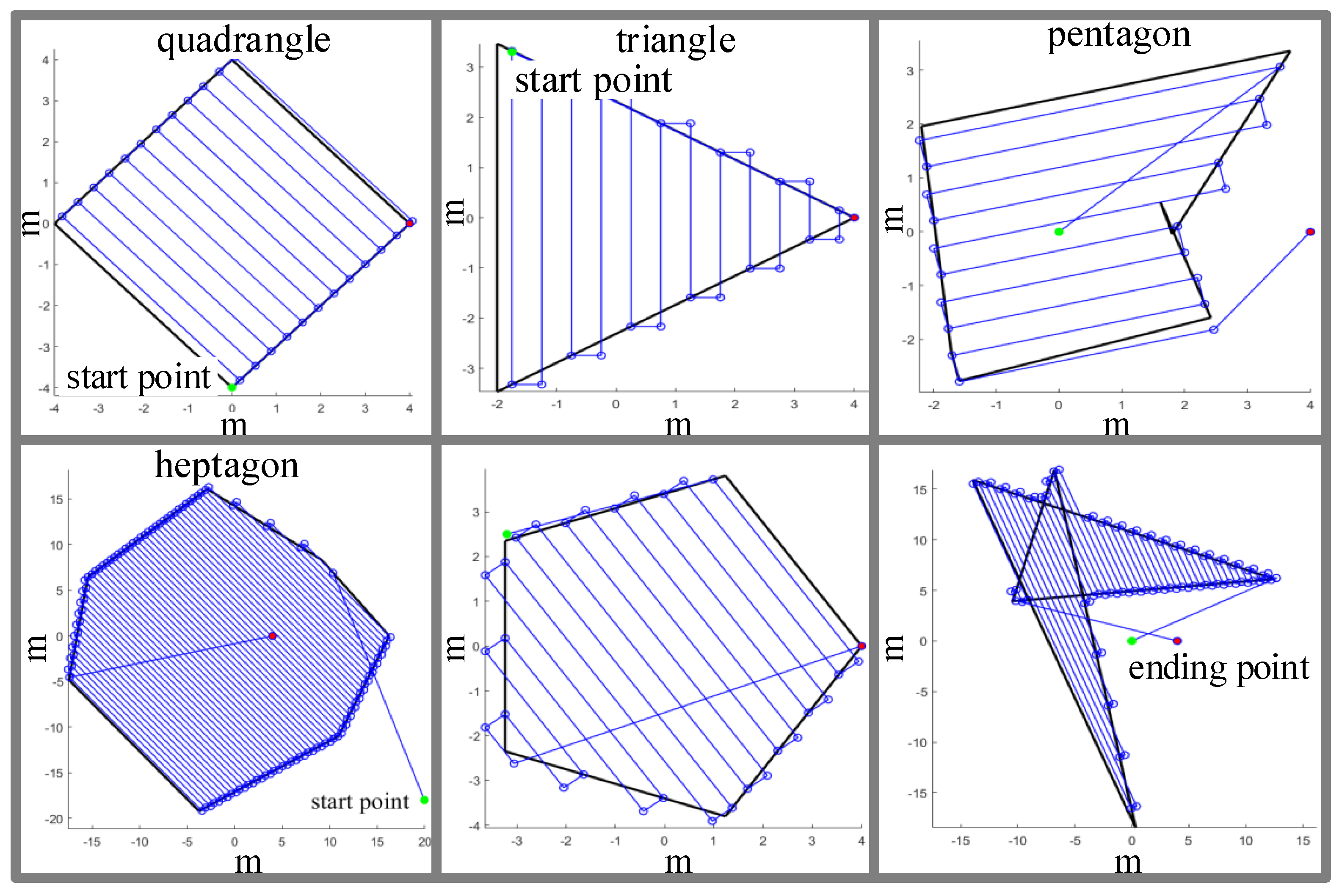
For this simulation, the scenarios are diversified, including standard, arbitrary, and concave polygons, while the antipodal pair is randomly selected. The size of scenarios varies from to and is used to describe the unfolded shapes of the disinfection areas as much as possible. Since the nozzle is assumed to spray uniformly, the scanning radius is defined as in the simulation.
Figure 6 shows the results of the CPP algorithm, in which the black solid line represents the disinfection area, and the solid circles are the initial and terminal points. Some of the points are determined by calculation, while the rest are randomly selected. The lines are the end coverage paths, which are the final results after planning. Based on the proposed algorithm, the path covers every corner to ensure the full disinfection of the surfaces; key points in this path are important for the robot’s motion. It can be observed that the proposed algorithm achieves the minimum redundant paths in all environments when they complete the same amount of coverage tasks. This observation is consistent with the results of the theoretical analyses in the third section.
4.3. Validation for Robot Disinfection in Simulation
To demonstrate the applicability of the robot and the proposed algorithm for epidemic prevention, a coverage path task is performed on a workbench. The overall size of the workbench is
(length, width, and height, respectively). These parameters are input into the algorithm as scene setting. The initial generalized coordinates of the robot and the workbench are given in the left subfigure of
Figure 5. All the initial values of joints (
) are defined as zeros.
Figure 7 shows snapshots of the simulated disinfection. The snapshot at t = 5 s (top left) shows the nozzle as it begins to spray the workbench. The snapshot at t = 20 s (top right) depicts the robot as it is nearly finished spraying the first workbench. The snapshot at t = 50 s (bottom left) shows the robot as it begins to disinfect the second workbench. The snapshot at t = 80 s (bottom right) represents the accomplished disinfection. More details of the simulation can be found in the attached video. First, the robot and the proposed algorithm achieve path coverage in 3D space, and the nozzle follows a trajectory planned by the proposed algorithm. Secondly, it is feasible and in accordance with the motion plan mentioned in the third section. The end effector can easily track the trajectory of the relatively complex and mobile platform. On one hand, if we remove the data of the path of the end effector as the key point, the CPP algorithm is more practical and more easily implemented. On the other hand, the higher the altitude of the mobile platform, the larger the path losses and the more robot hovering energy required. Thirdly, the nozzle is flexible to operate due to real-time communication, execution, and feedback between MATLAB and Vrep with minimal time delay.
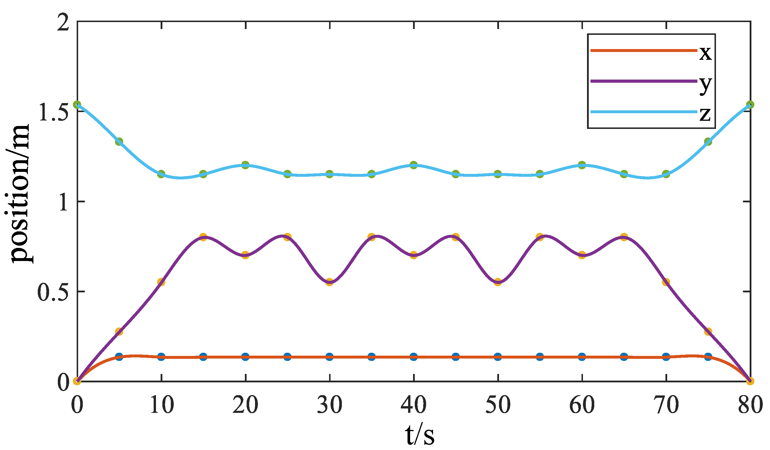
In order to express the performance of the end effector, the posture along the
,
, and
directionsis presented in
Figure 8; the trajectories are smooth during the whole simulation. At the beginning, the robot adjusts its height and direction to stay in a reasonable range within the workbench. Hence, the trajectory on the
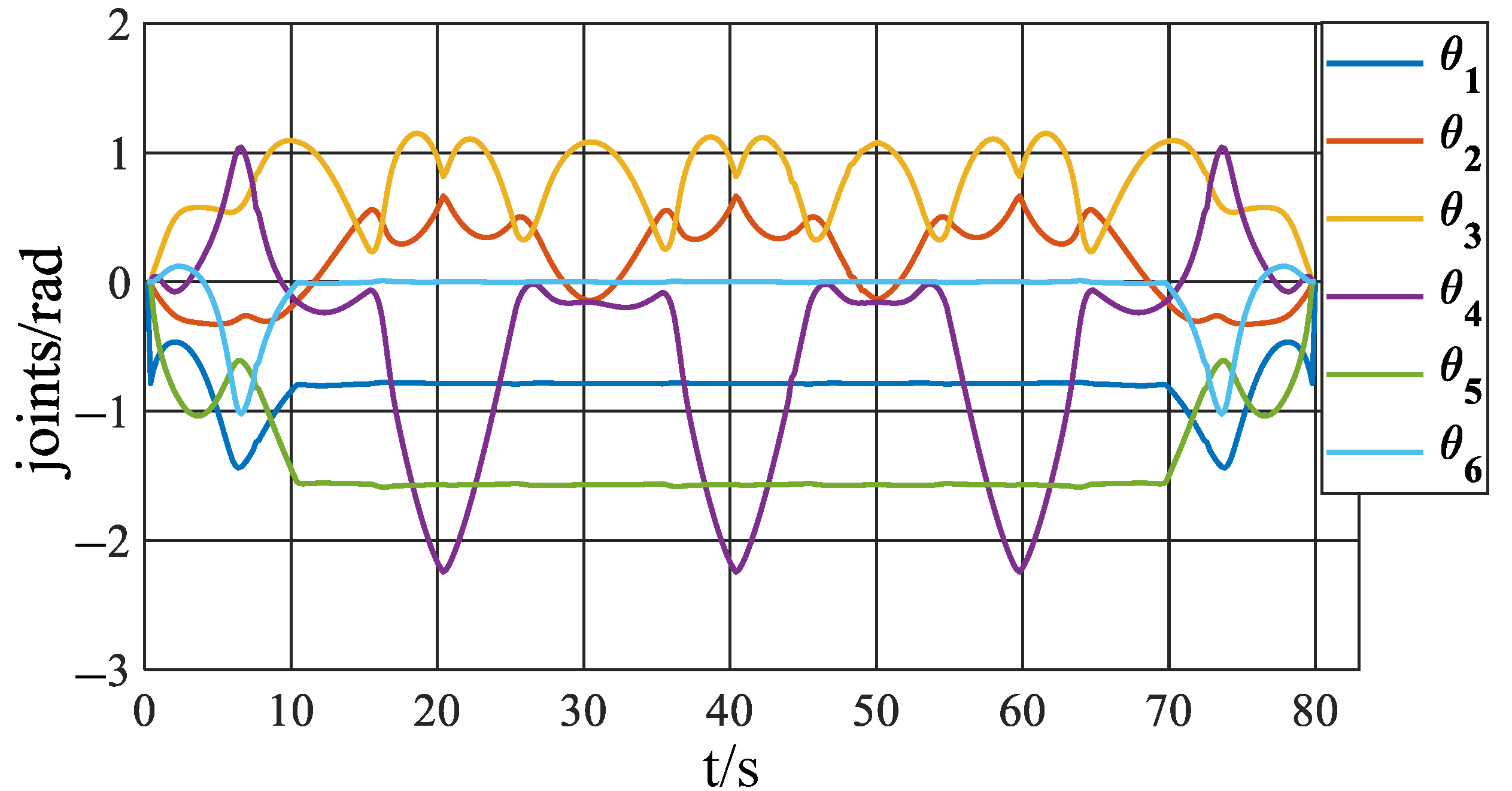
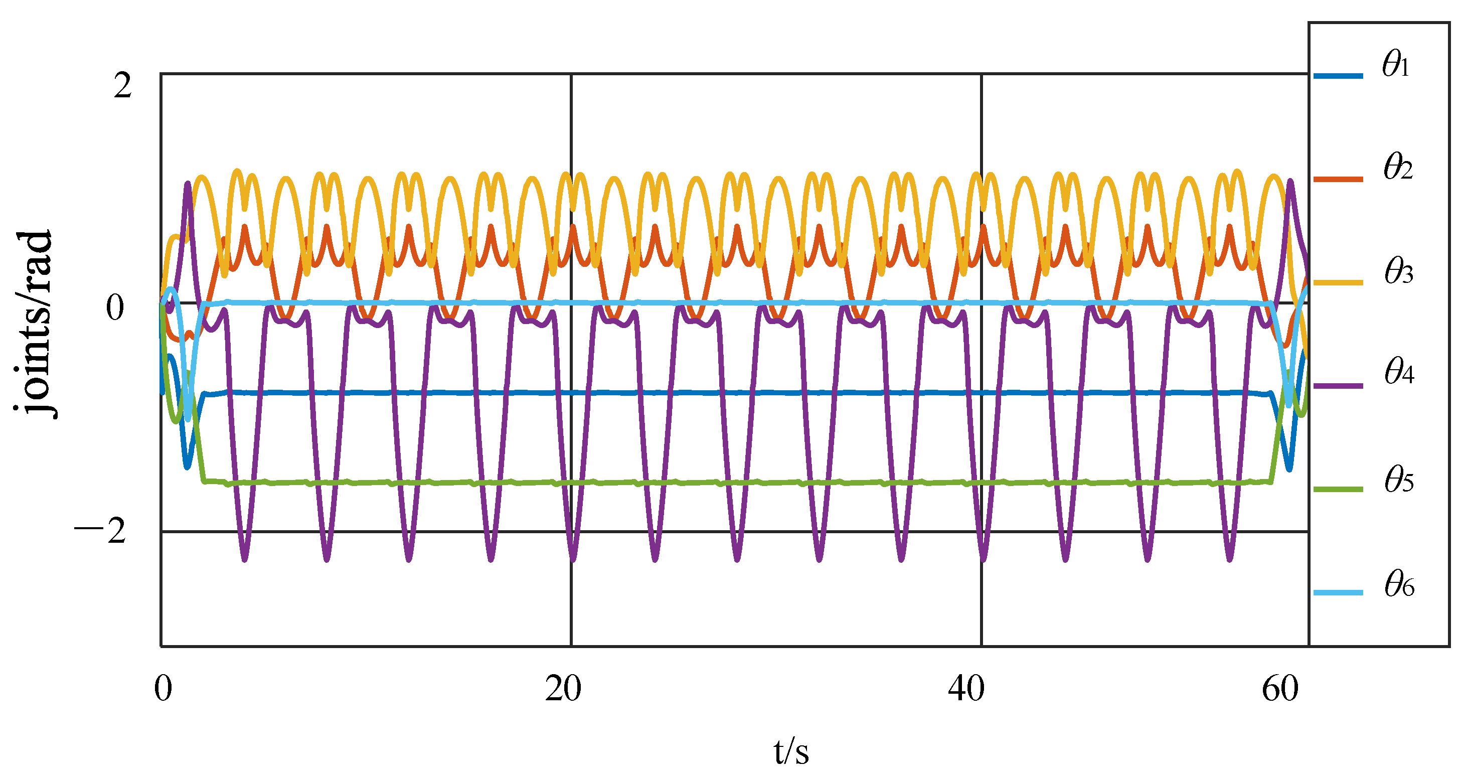
axis changes regularly. During the disinfection process, the trajectory is regular and smooth. The joint trajectories of UR5 are shown in
Figure 9, with a similar regularity in joint space. The disinfection robot has fewer constraints on its movement compared to the situation in the first simulation. Therefore, the algorithm can choose among a wide variety of trajectories, enabling separate evaluation of its capability. The goal of this simulation is to evaluate the disinfection performance of the optimized trajectory planning method described in the previous sections.
4.4. Experimental Validation of Robot Disinfection
In order to reproduce the properties of the disinfection robot in a physical environment, the configuration and parameters of the experiment are identical to those in the simulation.
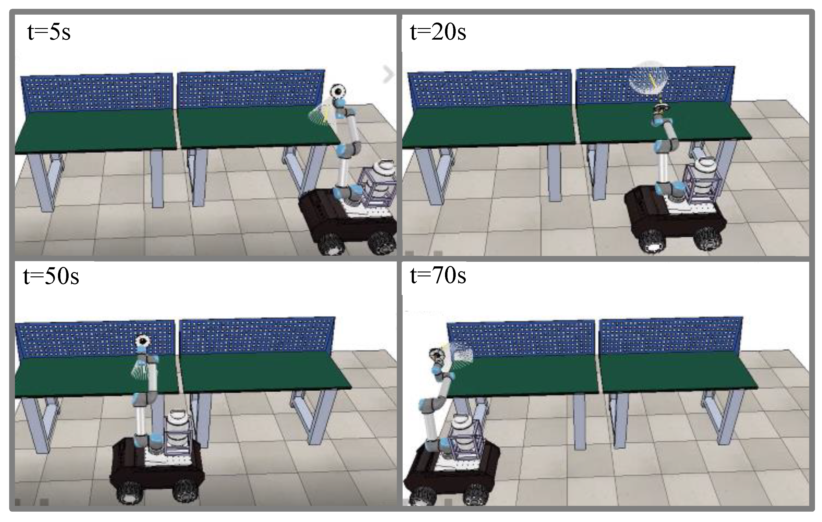
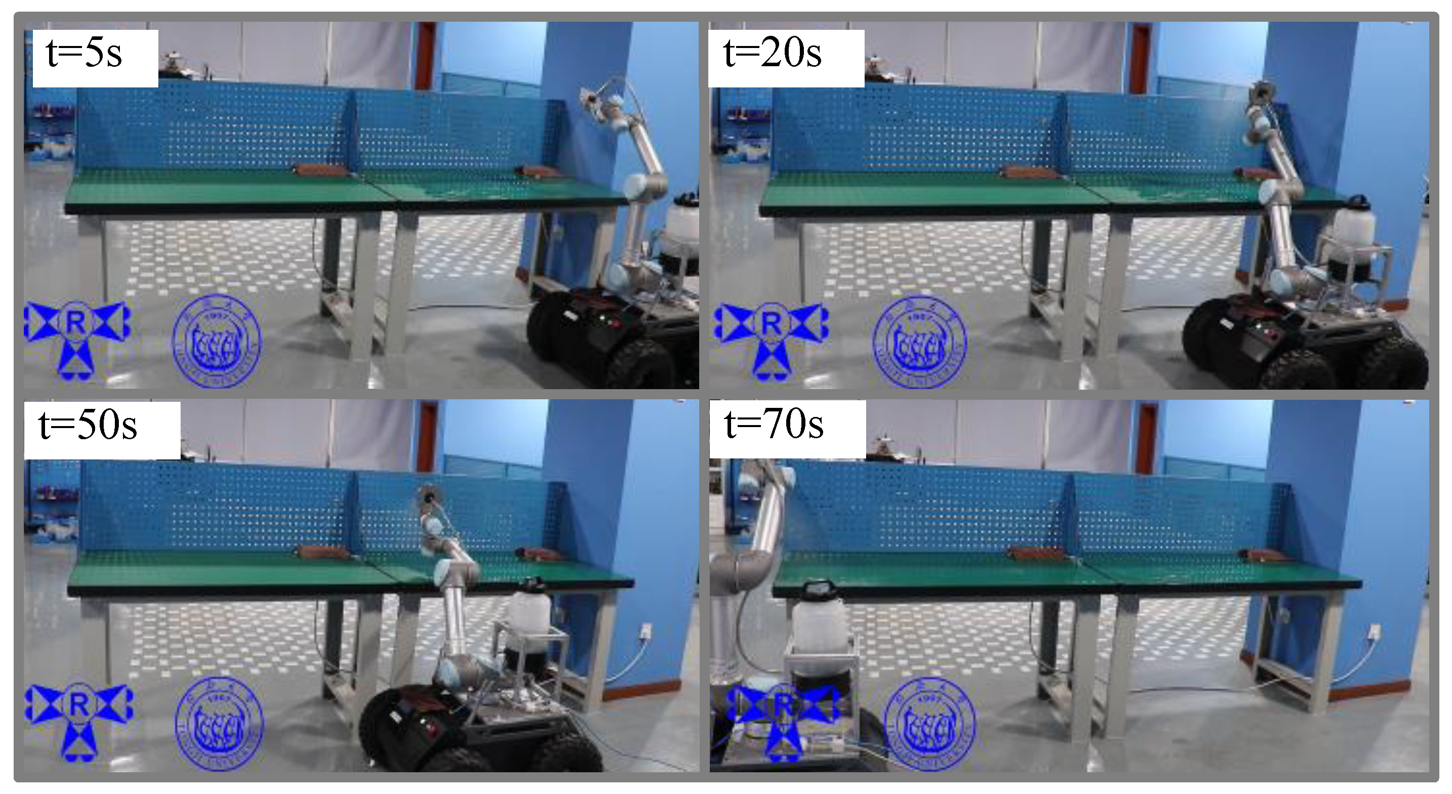
Figure 10 shows snapshots of the experimental disinfection. The snapshot at t = 5 s (the top left) shows the nozzle as it begins to spray on the workbench. The snapshot at t = 20 s (the top right) shows the robot as it is nearly finished spraying on the first workbench. The snapshot at t = 50 s (the bottom left) shows the robot as it begins to disinfect the second workbench. The snapshot at t = 70 s (the bottom right) represents the accomplished disinfection. More details of the experiment can be found in the attached video.
In this experiment, the robot and the proposed algorithm can achieve path coverage in real-world 3D space. Validation is conducted by seeking optimal trajectories on the horizontal and vertical surfaces, as shown in
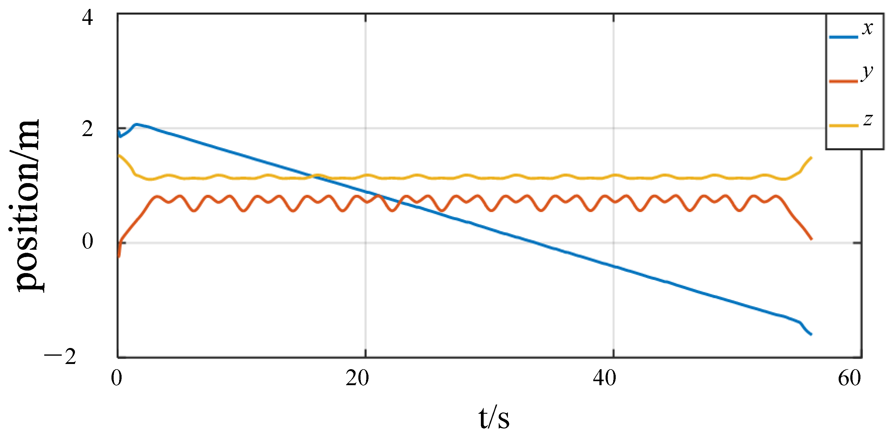
Figure 10. In order to express the performance of the end effector, the posture along the
,
, and
directionsis recorded in
Figure 11; the trajectories are similar to those in the simulation. At the beginning, the robot adjusts its height and direction to stay in a reasonable range within the workbench. Hence, the trajectory on the
axis changes less smoothly. During the disinfection process, the trajectories are regular and smooth. The joint trajectories of UR5 are shown in
Figure 12 with a similar regularity in joint space. The characteristics of the spray nozzle in the experiment have more influence on the performance parameters, such as actual wireless communication, spray homogenization, and thickness. We should also point out that this algorithm can handle a variety of surfaces in 3D space that humans usually touch. The results prove that the proposed disinfection robot is more suitable for spraying tasks in 3D space than regular (move-based) disinfection robots.
5. Conclusions
This research proposes an intelligent disinfection robotic system for the disinfection of common environments that humans often access. The robotic system utilizes multiple technologies, including a structural design, communication system, disinfection instrument framework, ROS1 and CPP, etc. The mobile manipulator can grant the disinfection robot more flexibility than common disinfection robots based on a mobile platform, enabling the determination of optimized trajectories that, although slightly complex, result in a better disinfection effect. Planning a feasible path is an important component of this study, for which the CPP algorithm is used to generate a rational coverage path in 3D environments. Simulations and an experiment were conducted to verify the feasibility and effectiveness of the robotic system. The proposed disinfection strategy enables the robot to automatically complete disinfection tasks throughout any target environment, thereby ensuring human safety and reducing labor required for manual disinfection. For future research, the robot can be made more intelligent and multifunctional, and more common environmental scenarios should be verified.
6. Patents
Qirong Tang, Xinyi Chen, Pengjie Xu. clamping mechanism and clamping device. Invention patent CN202111405539.1, 2022.12.27.
Qirong Tang, Xinyi Chen, Pengjie Xu. A clamping mechanism and a clamping device. Practical patent CN202122900939.1, 2022.4.9.
