Abstract
There are several compelling reasons for exploring the ocean, for instance, the potential for accessing valuable resources, such as energy and minerals; establishing sovereignty; and addressing environmental issues. As a result, the scientific community has increasingly focused on the use of autonomous underwater vehicles (AUVs) for ocean exploration. Recent research has demonstrated that buoyancy change modules can greatly enhance the energy efficiency of these vehicles. However, the literature is scarce regarding the dynamic models of the vertical motion of buoyancy change modules. It is therefore difficult to develop adequate depth controllers, as this is a very complex task to perform in situ. The focus of this paper is to develop simplified linear models for a buoyancy change module that was previously designed by the authors. These models are experimentally identified and used to fine-tune depth controllers. Experimental results demonstrate that the controllers perform well, achieving a virtual zero steady-state error with satisfactory dynamic characteristics.
1. Introduction
Ocean monitoring and exploration are tasks that have gained an increased importance in the past decades, due to both scientific and economic reasons. This has raised the need for more accurate and robust equipment, allowing a more permanent human presence at sea. The development of underwater vehicles has been one of the major trends in this field as they are much more robust than their surface counterparts. However, devising autonomous underwater vehicles poses several challenges, one of which being its energy autonomy. In this regard, underwater gliders have shown that it is possible to spend months or even years continuously monitoring oceans. This is possible given the low energy that gliders require since their working principle is based on punctual buoyancy changes, which might lead to significant energy savings in comparison with propeller-based vehicles [1]. At the core of an underwater glider is a buoyancy change device (BCD), responsible for changing the relationship between the vehicles’ mass and volume, thus ensuring a change in its buoyancy. The use of these devices is also at the core of profiler buoys. The Argo network [2] is one of the most successful and known Ocean monitoring programs that uses approximately 4000 profiler buoys, distributed throughout the world, enabling the real time monitoring of ocean conditions up to 2 km depth. Two interesting studies aim to extend the use of profiler buoys [3,4]. In these studies, the authors investigate the possibility of combining the low energy vertical motion of profile buoys, using BCDs, with a horizontal motion exclusively based on ocean currents. The authors of [3] developed a model and a control scheme ensuring that by actively and adequately choosing the oscillating tidal current direction, the float would eventually reach a neighbourhood of any desired destination. Since the main purpose of study [3] is to assess the effect of tidal currents in the horizontal direction, the float vertical motion model is a very simple one, without detailing the effects of the float structural deformation or effects due to the increase in the force acting on the BCD with pressure. Given that the main concern in [4] is also the horizontal motion of the float caused by currents, this simplifying approach to the vertical motion model is also followed in [4], where it is assumed that the float is represented dynamically as a point mass that can change depth instantaneously.
The use of BCD can also be found, in recent years, in the development of hybrid vehicles (using both propeller and a BCD), in an attempt to simultaneously achieve the manoeuvrability provided by the propellers with the low energy consumption provided by the BCD. In fact, a BCD allows the fine tuning of the neutral buoyancy of the vehicle, therefore reducing the energy that propeller-based vehicles require just to counterbalance the (typically positive) buoyancy, which is passively tuned. This is particularly important since changes in the pressure, temperature and salinity of the water make it impossible, from a practical standpoint, to tune the buoyancy of an underwater vehicle to zero in a passive way. Furthermore, there are certain hovering tasks for which the use of vertical thrusters interferes with the mission application, for instance when filming close to a muddy seafloor, as it would cause water clouding.
All the above-mentioned studies highlight the need to develop accurate depth controllers for BCD. It is possible to find several works in the literature addressing the depth control of underwater vehicles. For instance, in [5], a buoyancy control for an autonomous underwater vehicle designed for filming tasks is developed. The vehicle weight is 180 kg and has a maximum buoyancy change of 8 kg. The buoyancy change is obtained by injecting air from a compressed air source into four ballast tanks through a series of valves and manifolds that control and distribute air and water in the system. Unfortunately, no model of the system was determined, and in autonomous mode, the controller only uses thrusters for vertical motion. Buoyancy control is utilised only under fault conditions by means of a failsafe behaviour.
In [6], a buoyancy control device using two bellows actuated by linear drives is developed. The device appears to perform only at very shallow depths (up to 2 m). A second order, a type 0 linear model is used to develop a PID controller that performs depth control. However, no information on how the model was derived is presented. Furthermore, although experimental results are described as leading to a maximum error of 47% and a minimum of 2%, very few details are provided on how these results were found.
In paper [7], the motion model of a buoyancy-driven profiling float is determined analytically. The buoyancy change is achieved using a piston moving seawater in and out of the vehicle, similarly to what is utilized in this work. Depth control is performed using three different types of controllers, namely a conventional PD controller, a sliding mode controller and a segment PD controller, as proposed in that work. The segment PD controller controls depth velocity until the target depth is near and then switches to depth control around the target depth. Simulation and experimental results show that accurate depth control can be obtained with the proposed segment PD controller, since a maximum error of 0.3 m was obtained in experimental trials of up to 60 m depth. However, the results presented in this paper do not show any experimental validation of the depth motion model. Furthermore, the proposed model does not include the actuator dynamics nor the positive feedback due to the increase in water pressure with depth.
In paper [8], a complex nonlinear model of the depth motion dynamics of a profiling float is developed, along with the use of a finite-time boundedness controller. The float weighs 52 kg, its height is 0.82 m and its maximum width is 0.54 m. The dynamic model includes drag forces, hull deformation with pressure and the effects of vertical currents disturbing the system. Experimental results using the proposed control strategy show that steady state errors of up to 30 m for target depths of up to 300 m could be achieved. Unfortunately, no experimental validation of the developed model was performed.
In [9], a piston type buoyancy device is developed for integration in a lightweight hybrid aerial vehicle, which can dive up to 25 m. Both diving velocity and pitch angle control is achieved by controlling the piston position. Since these two controlled variables are coupled, a complex nonlinear model is developed for adequate controller development. Experimental results using a PID controller show that a reasonably good performance is achieved in pitch control, although a steady state error in diving velocity is obtained, which might compromise depth control. Once again, no results regarding the model validation are presented.
A novel approach has been devised in [10] to regulate depth for an autonomous buoy robot tasked with tracking spilled oil and blowout gas. The new algorithm utilized for regulating depth relies on contrasting the anticipated duration required for the buoy to alter its buoyancy from its current setting to the neutral position with the projected time for the robot to attain the intended depth. The algorithm’s effectiveness was established in sea trials, demonstrating that it is capable of seamlessly manoeuvring the buoy to the target depth with minimal overshooting. One of the claimed advantages of the control law presented in [10] is its versatility, as it does not necessitate a rigorous determination of the neutral buoyancy value.
An interesting study can be found in [11] on the depth control of a floating ocean seismograph. In these types of devices, designed to detect seismic ocean waves, a rapid reaction time, minimal overshooting, negligible steady-state error and strong robustness to ocean currents, marine creatures, etc., is required. To achieve these goals, in [11], a fuzzy sliding mode controller, taking into account the influence of seawater density change, is devised. The performance of this controller is compared in simulation with the performance of a traditional PID controller, a fuzzy PID controller and a sliding mode controller. Results of this comparison show that the controller proposed in [11] leads to the shortest settling time and minimum steady-state error and overshoot, while presenting good robustness to disturbing forces.
In order to develop accurate depth controllers, it is of upmost importance to have good models of its vertical motion behaviour. Indeed, the experimental development of controllers is impractical or economically unfeasible, since either test pools or sea trials must be performed, requiring high costs and time. This work contributes to this field by developing a comprehensive linearized model of the vertical motion of a device (either float or vehicle) that, contrary to previously presented models in the literature, includes actuator dynamics. Only the vertical motion is considered, as it is assumed that the device is either a float (for which pitch and roll are constant) or that these variables are controlled by the (other) vehicle actuators. This model is experimentally identified using a BCD previously developed by the authors [12]. Although it is a linearized model, it is demonstrated that it captures the relevant dynamics, therefore providing a very useful simulation tool in the development of depth controllers. The main scientific contributions of this paper are therefore the following: (i) the development of a linearized model of a BCD, including actuator and device dynamics, which can be used for devising controllers; (ii) an experimental identification of the devised model; and (iii) the development and experimental test of controllers, based on the identified model, for the BCD.
The paper is organized as follows: Section 2 briefly describes the prototype developed in this work, with special emphasis on the improved main control unit. Next, Section 3 presents the dynamic model of the vertical motion of the prototype as well as its experimental identification. Section 4 presents the controller proposed in this work and experimental results obtained when testing the prototype in a 5 m depth test pool. Finally, Section 5 summarizes the main conclusions of this work.
2. Prototype Description
In the literature, it is possible to find very different types of technological solutions for buoyancy compensation, including purely gas-stored pneumatic systems [13], linear electric drives that use seawater as a working fluid [14], hydraulic pumping systems [15], combinations of these solutions [16] or even thermal-actuated VBSs [17]. However, the majority of the solutions found in the literature are either linear electric drives that use seawater as a working fluid or oil hydraulic pumping systems [1], as schematically represented in Figure 1. In both cases, the principle of operation is based on increasing or decreasing the volume of the BCD, thereby changing its buoyancy, by pumping water or oil in or out of a sealed variable volume.
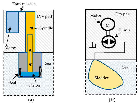
Figure 1.
Schematics of (a) electromechanical and (b) electrohydraulic BCD working principle.
The BCD used in this work (please see Figure 2) is designed to be installed in small size AUVs based on modular building blocks [18] or to be used as a standalone buoy to perform vertical profiling missions. It is designed for shallow waters (up to 100 m), to which the electromechanical solution is better suited [1]. The development of this prototype has been described in detail in [12], although the control unit has undergone several improvements, as described next, for the purposes of this work.
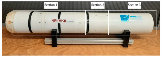
Figure 2.
Picture of the developed prototype.
It consists of three main sections: section 1 encompasses the buoyancy change module, section 2 is an intermediate section used to include flotation foam and section 3 is the main control unit (MCU). The MCU developed in this work is an independent module to be coupled to the BCD, so that the whole set can work as a float. If the BCD is incorporated into an existing AUV, then the MCU developed in this work is no longer required, as the control unit of the AUV may be used for that purpose. The buoyancy change is achieved by pumping water in and out using a diaphragm-sealed piston. The piston is driven by an electrical motor coupled to a mechanical transmission and a spindle. This BCD allows a total volume change of approximately cm3 and is able to dive up to 100 m. Its full length is 1285 mm with an outer radius of 200 mm. Its dry weight is 33 kg. Further details of the BCD can be found in [12].
In this work, the control unit of the BCD developed in [12] has been improved in order to allow the measurement of the depth and to implement depth control strategies. Figure 3 presents a schematic of the measurement and control devices as a whole, including the main control unit (MCU). This unit includes a Turnigy high capacity 14.8 V 4 Cell Battery for the power supply of both the MCU and the BCD. It also includes two DC–DC converters responsible for providing a correct and stable voltage to the Arduino Uno R3 (7 V) and the BCD (14 V). In order to measure depth, a Bar30 pressure sensor was mounted on the outside of the MCU. This sensor can measure up to 30 bar (300 m) and has a 0.2 mbar resolution, corresponding to a depth measurement resolution of 2 mm in the water column. It communicates via I2 C with the Arduino. An Ethernet Shield was mounted on the Arduino to establish an Ethernet connection with the PC used to retrieve data. This allows data logging and setting parameters, such as target depths, controller gains and maximum and minimum positions for the actuator during preliminary trials.
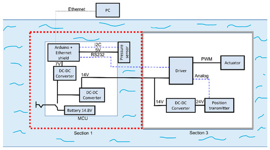
Figure 3.
Measurement and control devices.
Inside the BCD there is linear electrical actuator, driven by a DC-brushed motor, which moves the diaphragm-sealed piston. The motor driver (ROBOCLAW 2x15A) receives an analogue signal from a FESTO SDAT-MHS position transmitter that measures the position of the diaphragm-sealed piston. The driver is also responsible for modulating, using pulse width modulation (PWM), with the command voltage u applied to it. To supply the position transmitter, another DC–DC converter is used to convert the 14 V from the MCU to 24 V. The Arduino at the MCU is responsible for running the control algorithm and communicating to the driver what the correct voltage to apply to the motor at any given time is, as well as recording the information retrieved by the driver (PWM percentage, actuator position, etc.).
3. Dynamic Model of the Vertical Motion of the Prototype
3.1. Model Development
Figure 4 presents a generic scheme of the working principle of the BCD used in this work. It includes a linear drive, represented in yellow, that moves a diaphragm sealed piston in and out, thereby expelling or absorbing sea water and thus changing the buoyancy. The forces acting on , the actuator and piston moving mass, are , which represents the force performed by the actuator; , the force exerted by the outside water pressure on the rolling diaphragm piston; and , the friction force on the actuator, assumed to be of the viscous type.
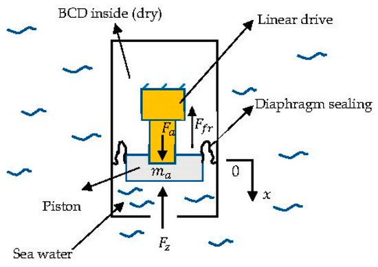
Figure 4.
Forces acting on the piston.
The forces acting on the prototype and added masses, , are represented in Figure 5. is the submerged prototype weight, is the buoyancy force caused by changing the immersed volume, is the change in buoyancy force caused by the deformation of the vehicle hull due to pressure and is the drag hydrodynamic force, assumed to be proportional to the square of the vehicle velocity [8].
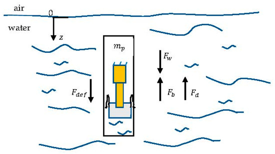
Figure 5.
Forces acting on the prototype structure.
It will be assumed that (i) when the piston of the buoyancy module is at its central position ( = 0), the submerged prototype weight () is compensated, leading to neutral buoyancy, and (ii) the actuator electrical dynamics are much faster than all the other dynamics and can therefore be modelled by a steady state gain, .
Applying Newton’s second law to the actuator and to the prototype and added masses (Figure 4 and Figure 5), respectively, leads to the following equations, where denotes the actuator position, the prototype depth and the initial conditions are assumed to be zero:
Please note that due to assumption (i) above, the prototype weight does not appear in Equation (2).
The block diagram of Figure 6 details the motion model of the system. By expanding Equations (1) and (2), Equations (3) and (4) can be found, where denotes the actuator’s current to force gain, is the back EMF gain, is the motor electrical dynamics’ steady state gain and is the viscous friction coefficient acting on the actuator. It is assumed that given the maximum depth range of the BCD, the relationship between the outside water pressure and the corresponding force on the actuator is essentially linear and described by , where , with the volumetric mass of water, assumed to be constant; is the acceleration of gravity; and is the area of the diaphragm piston. is the hydrodynamic drag coefficient, is the constant relating the hull deformation with the corresponding buoyancy force decrease and is the gain between the actuator position x and the corresponding change in buoyancy force.
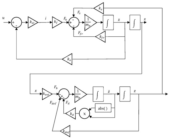
Figure 6.
Prototype depth model block diagram.
Equation (3) is linear, but Equation (4) is nonlinear due to the drag force. From a control perspective, it is interesting to have a linearized model around a steady state () equilibrium point ():
This model can be simplified by neglecting the influence of the hull deformation due to pressure (), as the pressure hull was designed to be essentially incompressible for its depth range. In this case, the linearized model can be written in the Laplace domain as:
In order to identify the transfer functions (7) and (8), several experimental trials were performed, as presented in the next section.
3.2. Model Identification
The experimental trials were performed in a 5 m depth pool. Two sets of experiments were performed. In experiment 1, designed to identify model (7), the BCD was actuated with different voltages steps (±2.5, ±5, ±7.5, ±10) V, corresponding to different PWM (±17.9, ±35.7, ±53.6, ±71.4) %DC values and corresponding to the steady state velocities of the piston motion. In experiment two, the actuator was moved to several positions around its central position (corresponding to neutral buoyancy), corresponding to different terminal velocities of the prototype. Results from experiment 1 and 2 were then collected in a text file in the PC connected to the BCD via a cable in order to identify the parameters of first order models (7) and (8), respectively. In experiment 1, the actuator started at either x = −20 mm or x = 20 mm, with a zero-voltage set. Then, a positive or negative voltage was applied, until a total travel of approximately 40 mm was reached (please see Figure 7a,b) for an example). When this occurred, the voltage was once again set to zero. Since different voltages, corresponding to different steady state velocities, were used, the length of the trials shown in Figure 7, which presents the results of this experiment, are not constant. The velocity of the actuator was estimated using finite centred differences on the measured piston position. In experiment 2, the piston position was moved from the central position to several positions around it (0 → 9; 0 → −9; 0 →13; 0 → −13; 0 → 17; 0 →−17; 0 →21; 0 → −21) mm and the depth of the BCD was measured and recorded on the PC until the BCD reached either surface level or the bottom of the pool. The depth velocity was estimated, once again, using finite centred differences. The sampling frequency was 50 Hz. The identification was performed using the system identification toolbox of MATLAB using all trials in each experiment. Since the experiments described above were carried out in shallow waters and, in this work, the piston position was actively controlled with a feedback controller, it was expected that the influence of the disturbance due to the increase in water pressure with depth, expressed in the second transfer function of Equation (7), would be essentially negligible. Under these conditions, the model identification results are shown in Equation (9) for model (7) and in Equation (10) for model (8). It should be noted that, based on the linear actuator manufacturer’s information and on certain physical considerations, further detailed parameters of Equations (7) and (8) could be estimated. However, the model devised in this work is meant to be used from a control perspective, namely to be able to develop controllers in simulation, thereby avoiding the impractical or economically unfeasible task of experimental parameter tuning. From this perspective, the identification of the overall steady state gains and time constants is sufficient.
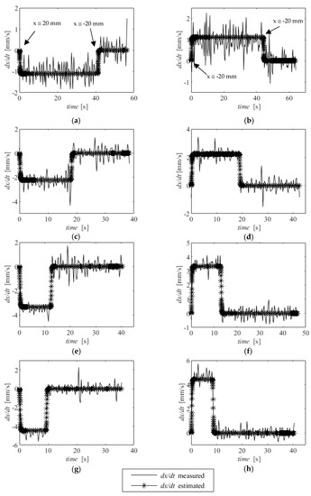
Figure 7.
Identification results for experiments 1: (a) u = −2.5 V, (b) u = 2.5 V, (c) u = −5 V, (d) u = 5 V, (e) u = −7.5 V, (f) u = 7.5 V, (g) u = −10 V and (h), u = 10 V.
Figure 7 and Figure 8 show a comparison between the experimental data and the data predicted by models (9) and (10). It can be seen that a good overall fit is found.
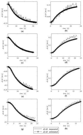
Figure 8.
Identification results for experiments 2: (a) x: 0 → 9 (mm), (b) x: 0 → −9 (mm), (c) x: 0 →13 (mm), (d) x: 0 → −13 (mm), (e) x: 0 → 17 (mm), (f) x: 0 →−17 (mm), (g) x: 0 →21 (mm), (h) x: 0 → −21 (mm).
4. Controller Development and Experimental Results
In this section, two depth controllers are developed. It should be underlined that the ultimate goal of this paper is not to finely tune the controllers in order to reach the best possible performance but rather to show that it is possible to reach, in simulation, controller parameters that work in a real environment using the identified system model.
4.1. Controller Structure
Using the model identified in the previous section, the overall controller structure developed in this work is presented in Figure 9. An outer loop is used to control the depth of the BCD (), while an inner loop is used to control the actuator position (). The use of this structure is advantageous, as it allows the decoupling between the actuator and vehicle dynamics, allowing the rejection of the disturbances caused by the increase in pressure with depth. Additionally, by using a cascade controller, the controlled inner actuator position dynamics becomes a type 0 dynamic, which contributes to increase the stability of the system.

Figure 9.
Controller structure used in this work.
In this work, a proportional controller was used for while PI and PID controllers were used for . The controller parameters were heuristically tuned in simulation to determine adequate controller parameters for experimental use. Table 1 presents the parameters that were found.

Table 1.
Controller parameters used in experimental trials.
Both integral and derivative actions were numerically implemented in the Arduino, using trapezoidal and backwards approximations, respectively.
4.2. Controller Experimental Results
Experimental results obtained when testing the PI controller with depth steps of different amplitudes are presented in Figure 10. The target depth is achieved with an absolute error lower than 5% in all cases. It should be noted that (i) the position transducer has significant noise and, (ii) as expected in a PI controller, the dynamic response has low damping, given the loss of phase margin introduced by the integral factor.
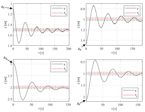
Figure 10.
PI depth controller experimental results: z is the BCD depth, zt is the target depth and the dashed dot lines represent a ±5% band around zt.
A last experiment with the PI controller was performed with the depth reference set at 1.5 m and the BCD starting point at approximately 3.7 m. This trial was carried out with three goals in mind: (i) the determination of the step response for higher amplitude steps, (ii) the evaluation of the ability of the controller to achieve a nearly zero steady state error and (iii) deliberately starting the integrator far away from zero to evaluate whether it converged to the value corresponding to a neutral buoyancy ). In fact, with the structure of the controller represented in Figure 9, and assuming that zero steady state error is achieved, the integral action in the depth controller theoretically represents the value of the piston position that leads to zero buoyancy. This is very interesting from an operational perspective, as it allows an easy and possibly automated way to implement an otherwise complex task, which is to accurately determine the zero-buoyancy actuator position. Depth control results are presented in Figure 11, and the integral action evolution is presented in Figure 12. As can be seen in Figure 11, a nearly zero (±0.02 m) error is obtained. Given the noise presented by the transducers, this is believed to be an encouraging result. Additionally, Figure 12 shows that the integral action of the controller converges to a nearly zero value, thereby confirming that it is able to determine the neutral buoyancy position.
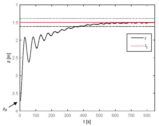
Figure 11.
PI control, step response to evaluate steady state error: z is the BCD depth, zt is the target depth and the dashed dot lines represent a ±5% band around zt.
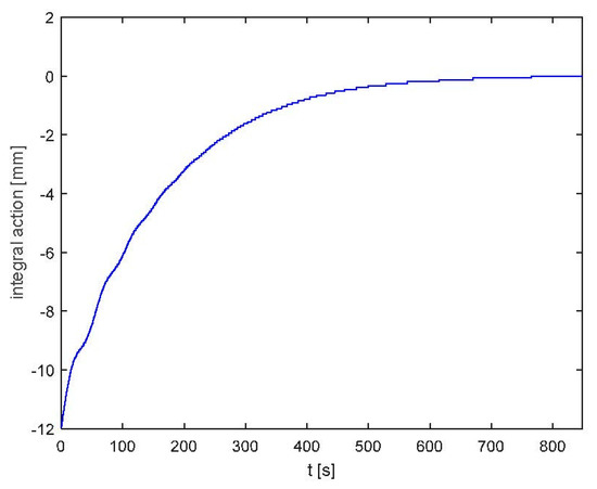
Figure 12.
PI control: integral control action evolution.
Finally, in order to dampen the responses obtained with the PI controller, a PID controller was developed. This controller was once again tested using several depth steps of different amplitudes. Results for the measured and target depth are presented in Figure 13, while the integrator evolution from all trials is presented in Figure 14.
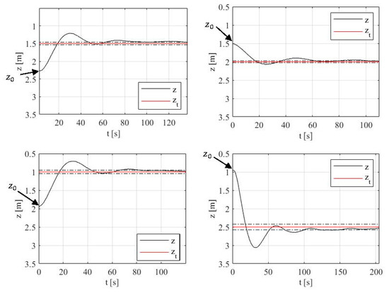
Figure 13.
PID depth controller experimental results: z is the BCD depth, zt is the target depth and the dashed dot lines represent a ±5% band around zt.
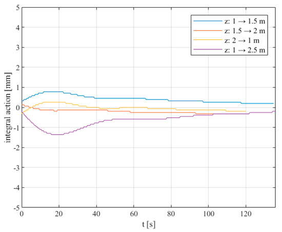
Figure 14.
PID depth controller: integral action evolution over time of the trials shown in Figure 13.
Regarding Figure 13, the results show that the controlled system is able to reach an error band of 5% with considerably low oscillations in all cases, thereby showing the effectiveness of the derivative control action. Regarding Figure 14, it is interesting to note that the steady state value of the integral action in all experiments is approximately the same as in Figure 12, thus experimentally verifying the adequacy of this procedure.
5. Conclusions
The use of BCD is of upmost importance in the development of underwater vehicles, as it provides an effective means to reduce the vehicles’ energy consumption. Despite this, the literature is scarce regarding the BCD depth motion model, which is critical to developing adequate controllers. This work contributes to the field by presenting the modelling and control of a buoyancy change device prototype. Based on a previous prototype developed by the authors, a detailed presentation of a new main control unit is presented. A dynamic model of the depth motion of the prototype is designed and experimentally identified with good results. This model is used to devise PI and PID controllers that are experimentally tested in a 5 m depth pool. Results show that a very accurate depth control is achieved, with virtually zero steady state errors. A maximum overshoot of around 30% and an average settling time of 100 s was obtained. Future works will focus on (i) studying the stability of the model developed, (ii) testing the prototype in deeper waters and (iii) implementing and testing advanced depth control strategies, namely by trying to optimize energy consumption.
Author Contributions
Conceptualization, J.F.C., F.G.d.A. and N.A.C.; methodology, J.F.C., F.G.d.A. and N.A.C.; software, J.B.P.; investigation, J.F.C., F.G.d.A. and N.A.C.; writing— J.F.C.; writing—review and editing, J.F.C., J.B.P., F.G.d.A. and N.A.C. All authors have read and agreed to the published version of the manuscript.
Funding
This work was financially supported through the grant LAETA—UIDB/50022/2020 from the “Fundação para a Ciência e Tecnologia”, which the authors gratefully acknowledge.
Data Availability Statement
Not applicable.
Conflicts of Interest
The authors declare no conflict of interest.
References
- Falcão Carneiro, J.; Pinto, J.B.; de Almeida, F.G.; Cruz, N. Variable Buoyancy or Propeller-Based Systems for Hovering Capable Vehicles: An Energetic Comparison. IEEE J. Ocean. Eng. 2020, 46, 414–433. [Google Scholar] [CrossRef]
- Argo—Part of the Integrated Global Observation Strategy. Available online: https://argo.ucsd.edu/ (accessed on 15 January 2023).
- Jouffroy, J.; Zhou, Q.; Zielinski, O. Towards Selective Tidal-Stream Transport for Lagrangian Profilers. In Proceedings of the OCEANS’11 MTS/IEEE KONA, Waikoloa, HI, USA, 19–22 September 2011. [Google Scholar]
- Smith, R.N.; Huynh, V.T. Controlling Buoyancy-Driven Profiling Floats for Applications in Ocean Observation. IEEE J. Ocean. Eng. 2014, 39, 571–586. [Google Scholar] [CrossRef]
- Love, T.; Toal, D.; Flanagan, C. Buoyancy Control for an Autonomous Underwater Vehicle. IFAC Proc. Vol. 2003, 36, 199–204. [Google Scholar] [CrossRef]
- Syafie, L.; Abidin, Z.; Rashid, N.K. Development of a buoyancy control device for Autonomous Underwater Vehicle. In Proceedings of the IEEE International Conference on Underwater System Technology: Theory and Applications (USYS), Penang, Malaysia, 13–14 December 2016. [Google Scholar]
- Bai, Y.; Hu, R.; Bi, Y.; Liu, C.; Zeng, Z.; Lian, L. Design and Depth Control of a Buoyancy-Driven Profiling Float. Sensors 2022, 22, 2505. [Google Scholar] [CrossRef] [PubMed]
- Qiu, Z.; Wang, Q.; Li, H.; Yang, S.; Li, X. Depth Control for a Deep-Sea Self-Holding Intelligent Buoy Under Ocean Current Disturbances Based on Finite-Time Boundedness Method. IEEE Access 2019, 77, 114670–114684. [Google Scholar] [CrossRef]
- Hu, R.; Lu, D.; Xiong, C.; Lyu, C.; Zhou, H.; Jin, Y.; Wei, T.; Yu, C.; Zeng, Z.; Lian, L. Modeling, characterization and control of a piston-driven buoyancy system for a hybrid aerial underwater vehicle. Appl. Ocean. Res. 2022, 120, 102925. [Google Scholar] [CrossRef]
- Choyekh, M.; Kato, N.; Yamaguchi, Y.; Dewantara, R.; Senga, H.; Chiba, H.; Yoshie, M.; Tanaka, T.; Kobayashi, E. Depth Control of AUV Using a Buoyancy Control Device. In Mechatronics and Robotics Engineering for Advanced and Intelligent Manufacturing; Lecture Notes in Mechanical, Engineering; Zhang, D., Wei, B., Eds.; Springer: Berlin/Heidelberg, Germany, 2017. [Google Scholar]
- Huang, H.; Zhang, C.; Ding, W.; Zhu, X.; Sun, G.; Wang, H. Design of the Depth Controller for a Floating Ocean Seismograph. J. Mar. Sci. Eng. 2020, 8, 166. [Google Scholar] [CrossRef]
- Falcão Carneiro, J.; Pinto, J.B.; Almeida, F.G.; Cruz, N.A. Design and experimental tests of a buoyancy change module for autonomous underwater vehicles. Actuators 2022, 11, 254. [Google Scholar] [CrossRef]
- Wolek, A.; Burns, J.; Woolsey, C.; Quenzer, J.; Techy, L.; Morgansen, K. A maneuverable, pneumatic underwater glider. In Proceedings of the 2012 Oceans, Hampton Roads, VA, USA, 14–19 October 2012. [Google Scholar]
- Ranganathan, T.; Singh, V.; Thondiyath, A. Theoretical and Experimental Investigations on the Design of a Hybrid Depth Controller for a Standalone Variable Buoyancy System—vBuoy. IEEE J. Ocean. Eng. 2018, 45, 414–429. [Google Scholar] [CrossRef]
- Asakawa, K.; Hyakudome, T.; Ishihara, Y.; Nakamura, M. Development of an underwater glider for virtual mooring and its buoyancy engine. In Proceedings of the 2015 IEEE Underwater Technology (UT), Chennai, India, 23–25 February 2015. [Google Scholar]
- MacLeod, M.; Bryant, M. Dynamic Modeling, Analysis, and Testing of a Variable Buoyancy System for Unmanned Multidomain Vehicles. IEEE J. Ocean. Eng. 2017, 42, 511–521. [Google Scholar] [CrossRef]
- Webb, D.C.; Simonetti, P.J.; Jones, C.P. Slocum: An Underwater Glider Propelled by Environmental Energy. IEEE J. Ocean. Eng. 2001, 26, 447–452. [Google Scholar] [CrossRef]
- Cruz, N.A.; Matos, A.C.; Ferreira, B.M. Modular building blocks for the development of AUVs—From MARES to TriMARES. In Proceedings of the 2013 IEEE International Underwater Technology Symposium (UT), Tokyo, Japan, 5–8 March 2013. [Google Scholar]
Disclaimer/Publisher’s Note: The statements, opinions and data contained in all publications are solely those of the individual author(s) and contributor(s) and not of MDPI and/or the editor(s). MDPI and/or the editor(s) disclaim responsibility for any injury to people or property resulting from any ideas, methods, instructions or products referred to in the content. |
© 2023 by the authors. Licensee MDPI, Basel, Switzerland. This article is an open access article distributed under the terms and conditions of the Creative Commons Attribution (CC BY) license (https://creativecommons.org/licenses/by/4.0/).