Abstract
Motion control of truck-mounted concrete pump booms is an important part of concrete construction work. The quality of the boom movement will affect the efficiency and safety of construction operations. To make the boom move quickly and steadily, its hydraulic control system needs to be improved. In this article, we firstly combine independent metering control (IMC) and active disturbance rejection control (ADRC). The hydraulic system that controls the boom is meliorated by replacing the traditional proportional directional spool valve with four cartridge flow control valves to realize IMC. Meanwhile, a fuzzy linear ADRC algorithm is proposed for a new IMC hydraulic system where ADRC is linearized and combined with fuzzy logic to achieve better motion control performance of boom sections. According to the results of experiments conducted using all six boom sections, compared with the PID control algorithm, the fuzzy linear active disturbance rejection control (FLADRC) proposed in this article can improve the stability and rapidity of valves controlled by hydraulic cylinders by 10.0% to 66.7% in different working conditions.
1. Introduction
Truck-mounted concrete pumps play a crucial role in construction work, aiming to complete concrete placing tasks efficiently, quickly, and accurately [1]. To achieve this, the hydraulic-controlled boom system must effectively deploy and arrange the conveying pipe. The stability and rapidity of its movement determines the quality and efficiency of concrete placement. The motion of the boom sections is controlled by hydraulic cylinders between them, so the control performance of the hydraulic system directly affects the movement performance of the boom system.
In the hydraulic field, independent metering control (IMC) technology, which separates the mechanical connections between metering ports, is an effective approach to enhance control flexibility [2]. The IMC system can be designed with various valves and configurations [3]. Using four 2/2 valves is one of the most popular ways to realize an IMC system. Zhang, Q. used four spool-type two-way cartridge valves to realize the function of a four-way directional valve [4,5]. Bin, Y. used four proportional cartridge valves to control one cylinder and an extra valve to implement a regeneration mode [6,7,8]; based on this, Lu, L. used four proportional cartridge valves and one accumulator to minimize the energy consumption of the system while maintaining good motion tracking performance [9,10]. Shenouda, A. used four electro-hydraulic poppet valves to construct an IMC system on a mid-size tractor loader backhoe and first proposed the concept of continuously variable modes [11,12,13]. Andrea, V. used four valves to control a truck-mounted crane [14]. Kyujeong, C. conducted a simulation of a four-valve IMC on an excavator using AMESim [15], Jong-Chan, L. used a five-valve IMC on a 20-ton crawler excavator [16], and KaiLei, L. conducted simulation research of a five-valve IMC together with a pressure compensation valve [17]. In addition, based on a four-valve IMC system, some researchers used more valves to construct an IMC system; for example, STEAM [18] used eight valves and DFCU [19] used twenty valves.
Active disturbance rejection control (ADRC) is a novel model-free control strategy whose exciting performance has been demonstrated in the literature. Han, J. first proposed the concept of ADRC, which is an evolutionary style of PID [20]. ADRC has already been used in many kinds of hydraulic systems, such as electro-hydraulic position servo control systems [21], aircraft electro-mechanical actuators [22], hydraulic quadruped robots [23], hydraulic-driven winches [24], exoskeleton joints [25], hydraulic AGC systems [26], hydraulic active suspensions [27,28] and missile electro-hydraulic actuators [29].
Gao, Z. linearized an ADRC algorithm and proposed the concept of LADRC (linear ADRC) [30]. Unlike a traditional ADRC algorithm, which has 11 parameters to be adjusted according to the system configuration, LADRC only has 3 parameters that should be regulated. Application of LADRC in hydraulic controls has already been conducted by many researchers. Quan, L. studied a reduced-order model-based LADRC on a hydraulic servo system using singular value perturbation theory [31]. Huang, J. adopted a sixth-order LADRC in the closed-loop position control of a hydraulic cylinder in a multi-joint hydraulic manipulator [32]. Wang used an LADRC with a reconstructed model to accomplish high-precision motion control of a hydraulic position servo system [33]. Jin, K. applied an LADRC with acceleration feed-forward on displacement tracking of a valve-controlled asymmetric cylinder [34]. Liu, F. designed an LADRC controller with residual dead-zone compensation for a hydraulic position servo system of a weeding machine [35].
Combining LADRC with fuzzy control can further improve the dynamic performance of the system; for example, Zhou, X. used an FLADRC to control medium- and high-voltage distribution networks [36], Sun, C. used an FLADRC to control an industrial quadrotor UAV [37] and flying robot [38], Zhang, F. used an FLADRC to control a deep-sea AUV [39], Han, D. used an FLADRC to control autopilot attitude [40], Feng, X. used an FLADRC to control an IPMSM [41], and Qing, Y. used an FLADRC to control a permanent magnet–electromagnetic hybrid suspension platform [42].
The previous studies mostly focused on system configurations and control algorithms and utilized small-scale hardware-in-the-loop test setups. This article, however, presents an experiment conducted on a full-scale truck-mounted concrete pump with a six-section boom that can reach 63 m in length. We developed fuzzy-LADRC controllers to control the speed and pressure of the hydraulic cylinders on the boom.
The main objectives of this paper were to achieve low-vibration speed control for the hydraulic cylinders controlled by independent metering valves and to minimize the speed response time using the fuzzy-LADRC approach. The experimental results for speed response control indicate that fuzzy-LADRC controllers can effectively reduce fluctuations and improve cylinder speed response time during the motion control of the truck-mounted concrete pump boom.
2. System Configuration
2.1. The Test Rig
Due to limitations with the counterbalance valve, regeneration modes were not feasible. As a result, a five-valve or more IMC configuration could not be used in the boom hydraulic system. To overcome this, we have chosen a four-valve configuration for improved accuracy in motion control of the boom sections.
Cartridge flow control valves were used instead of spool valves, providing several advantages. For instance, a cartridge valve has a seat that reduces leakage, which is essential for the boom hydraulic system. Furthermore, a high-pressure and a low-pressure piping system are employed to supply oil to the IMC valves in the hydraulic cylinder system of each boom section, as the pressure of the truck-mounted concrete pump hydraulic system cannot be altered.
Figure 1 illustrates the schematic structure of the IMV-controlled hydraulic systems that regulate the motion of the boom sections (IMCHB).
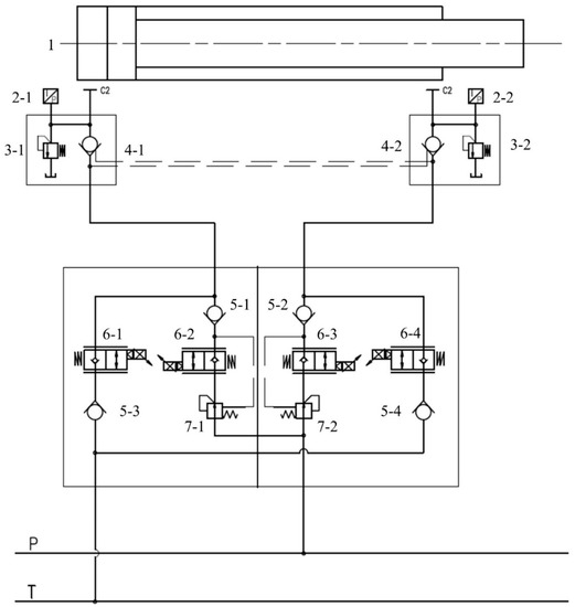
Figure 1.
IMC valve-controlled hydraulic cylinder concrete pump boom system. 1. Hydraulic cylinder 2. Pressure sensor 3. Safety valve 4. Counterbalance valve. 5. Check valve 6. Proportional flow control valve 7. Pressure compensator.
As seen in Figure 1, the “P” line represents the high-pressure piping system, which carries compressed hydraulic fluid from the pump. The “T” line represents the low-pressure piping system that is connected to the tank. The four proportional flow valves have a one-way flow function in the neutral state.
The oil inlet proportional flow valves (6-2 and 6-3) allow fluid to flow from the working port to the high-pressure oil pipeline, while the oil return proportional flow valves (6-1 and 6-4) allow fluid to flow from the oil return pipeline to the working port. To prevent oil leakage, a check valve is installed between the oil return proportional flow valve and the oil return pipeline, and another check valve is installed between the oil inlet proportional flow valve and the working chamber of the hydraulic cylinder. These check valves ensure that the oil remains locked when the flow control valves are in a neutral position.
2.2. The Numerical Model
2.2.1. Modelling of Hydraulic System
According to Newton’s third theorem, the force on the piston rod of the hydraulic cylinder is:
where F is the driving force of the valve-controlled cylinder; P1 and P2 denote pressures inside the two chambers of the cylinder; A1 and A2 are the ram areas of the two chambers; y is the piston rod displacement; mp is the equivalent mass of the cylinder piston rod and its load; cp is the equivalent damping coefficient of the cylinder piston rod and its load; FL is the resultant external force that includes the cylinder piston rod external load, unmodeled friction, and the sum of other uncertain external disturbance forces.
Since the mathematical models of the two chambers of the hydraulic cylinder are the same, in order to avoid repeated modeling, assuming that Q1 is the flow rate of the oil inlet chamber and Q2 is the flow rate of the oil outlet chamber, the flow rate of the two chambers of the hydraulic cylinder can be expressed as
where Cd is the flow coefficient; W1 is the area gradient of the oil inlet valve; W2 is the area gradient of the oil outlet valve; x1 is the displacement of the oil inlet valve main spool; x2 is the displacement of the oil outlet valve main spool; Ps is the system oil supply pressure; Pr is the system oil-return pressure; and ρ is the hydraulic oil density.
Due to established hydraulic system sealing technology, external leakage of the hydraulic cylinder can be neglected, so the flow continuity equations of the two chambers are
where Cip is internal leakage coefficient; V1 and V2 are the volume of the hydraulic cylinder inlet and outlet chambers, respectively; and βe is the oil volume elastic modulus.
In order to establish the state space equation of the IMV-controlled linearized asymmetric hydraulic cylinder system (3), we have
where
According to (1)–(5), the state space equation of the studied system is
where
Considering that the response dynamics of the valve used in the study are much higher than the actuator’s operation frequency band, valve spool displacement is considered as hydraulic system control input.
2.2.2. Modelling of External Forces
For the sake of illustration, in this paper the hydraulic cylinder that controls the movement of a boom section i (i = 1, 2, 3, 4, 5, 6) is called cylinder #i (i = 1, 2, 3, 4, 5, 6).
For cylinder #1, boom section 1 is articulated as shown in Figure 2, according to Newton–Euler equations and trigonometric function, the resultant external force applied on cylinder #1 FAB can be expressed as
where Mf is the resultant resistance moment of boom section 1; LOA stands for the distance between O and A.

Figure 2.
Schematic of cylinder #1 and its linkage mechanism.
Similarly, for cylinder #i (i = 2, 3, 5) as shown in Figure 3, the resultant external force applied on cylinder #i FDE can be expressed as
where FC is the resultant resistance force that boom section i (i = 2, 3, 5) applies on linkage EBC; LBC stands for the distance between B and C; and LBE stands for the distance between B and E.

Figure 3.
Schematic of cylinder #i (i = 2, 3, 5) and its linkage mechanism.
For cylinder #4 as shown in Figure 4, the resultant external force applied on cylinder #4 FDE can be expressed as
where FC is the resultant resistance force that boom section 4 applies on linkage EBC; LBC stands for the distance between B and C; and LBE stands for the distance between B and E.
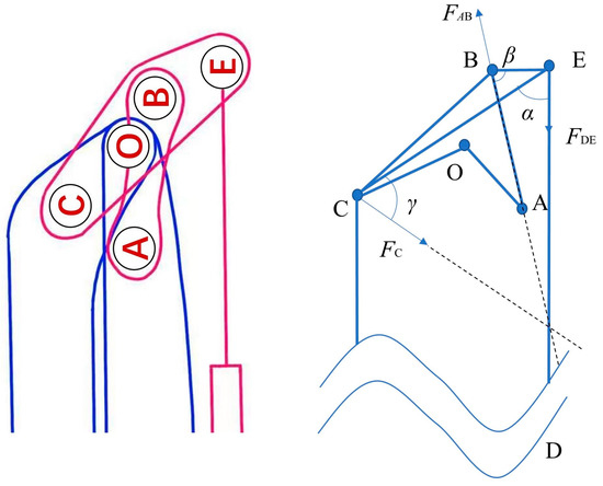
Figure 4.
Schematic of cylinder #4 and its linkage mechanism.
For cylinder #6 as shown in Figure 5, the resultant external force applied on cylinder #6 FDB can be expressed as
where FC is the resultant resistance force that boom section 6 applies on linkage BC.
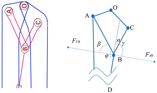
Figure 5.
Schematic of cylinder #6 and its linkage mechanism.
3. Control
3.1. LADRC Algorithm
ADRC, proposed by Han, J., uses several nonlinear functions such as fhan and fal in the design of its tracking differentiator (TD), extended state observer (ESO), and state error feedback. These nonlinear techniques effectively compensate for external disturbances and unknown model parts, but also increase the control algorithm’s complexity. Han, J. introduced the concept of “time scale” to categorize different systems and control processes. Based on the time scale concept, a single ADRC controller can be applied to systems with the same time scale, showcasing its potential for industrial applications. However, the need to tune up to 12 control parameters can hinder the use of ADRC.
Inspired by the time scale concept, Gao, Z. introduced the “frequency scale” concept. This associates ADRC parameters with frequency, making the physical sense of the parameters more intuitive. Furthermore, state error feedback and the extended state observer are implemented in a linear form. With the bandwidths of the feedback controller and extended state observer as their unique parameters, only three control parameters need to be tuned.
3.2. Control System Design
Our experiments have shown that a fixed set of controller parameters may not be optimal for systems under varying conditions. To achieve more precise and rapid control of boom cylinder speeds, we have integrated a fuzzy algorithm with the LADRC (linear active disturbance rejection control) method. This allows us to adjust the bandwidth of the feedback controller and extended state observer based on the system state.
The proposed control system as shown in Figure 6 consists of a fuzzy-LADRC speed controller, which regulates the inlet proportional flow control valve according to remote control commands and calculated cylinder speeds. The LADRC controller parameters are dynamically modified to produce an appropriate output to drive the inlet proportional flow control valve.
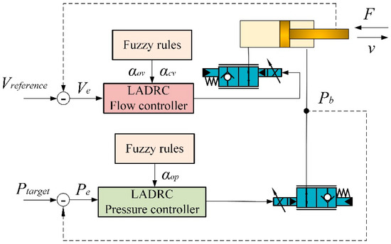
Figure 6.
Compound control pressure and flow structure of IMCHB.
Additionally, a fuzzy-LADRC pressure controller is used to control the outlet proportional flow control valve, with the goal of reducing pressure fluctuations in the hydraulic cylinder chambers.
3.3. Speed Controller Design
During the boom extension process, the external load of the hydraulic cylinder changes over time under the influence of friction forces, including friction torque between boom sections and connecting pieces and friction between the piston rod and the piston cylinder. Meanwhile, different arm postures will result in different center of gravity positions, so the gravity moments will also change over time, as shown in Figure 2, Figure 3, Figure 4 and Figure 5. In addition, because of the large scale of the test rig, many unpredicted influencing factors such as hydraulic system vibration [43] can lead to unstable cylinder dynamic performance, so the system model developed in Section 2 has model uncertainty as well as parameter uncertainty.
With all these uncertain influencing factors in mind, the LADRC algorithm was chosen to control the hydraulic cylinder speed because of its significant disturbance rejection capability. Furthermore, to increase speed control precision, we combined a fuzzy control algorithm together with LADRC, making the bandwidths of the feedback controller and extended state observer adjustable under different working conditions and stages.
For the system described in Equation (7), our goal was to generate suitable control input such that the piston rod speed can track the specified speed command as well as pressure target, so the rebuild state space equation of the system is as follows:
According to Equation (8), a second-order LADRC should be used to control the speed of the boom cylinders. To overcome the existing contradiction between stability and rapidity, a fuzzy-LADRC algorithm is applied in the speed control of cylinders, as shown in Figure 7.

Figure 7.
Boom cylinder speed control structure using FLADRC.
The control algorithm shown in Figure 7 is composed of three parts; the formula of the PD controller is
where ev is the speed tracking deviation, rv is the cylinder target speed, z1 is the observed value of cylinder speed, uv0 is the output value of the PD controller, z2 is the observed value of cylinder acceleration, kpv is proportional gain of the PD controller, and kdv is the differential gain of the PD controller.
Based on the concept of frequency scale, the value of kpv and kdv can be determined by controller bandwidth wcv, as shown:
The expression of the extended state observer is
where z3 is the observed value of the additional state variable, b0 is a rough approximation of the system control gain, β1v, β2v, and β3v are the observer parameters, and uv is the final output value of the control algorithm. According to the concept of frequency scale, the value of β1v, β2v, and β3v can be determined by observer bandwidth wov as shown:
Finally, the equation for the rest can be expressed as
As shown in the control algorithm, there are three controller parameters to be determined, which are controller bandwidth wcv, observer bandwidth wov, and system control gain b0. Controller bandwidth wcv determines controller response speed within a certain range; a larger wcv value can lead to better control performance. However, when the value of wcv becomes too large, the whole system may become unstable. As a consequence, the value of wcv should be adjusted according to the system’s transient response requirement and should be limited within a certain range so that precise measurement of the process variable can be obtained. Observer bandwidth wov determines the tracking speed of ESO; the larger the value of wov, the faster the estimation of disturbance. However, a large wov will lead to higher sensitivity to system noise and cause the observer to oscillate. Therefore, its value also depends on the acceptable noise threshold or the sampling delay that makes the state observer oscillate. System control gain b0 represents the properties of the object; it can be derived from the initial acceleration of system step response.
Increasing the value of wcv or wov will cause the high-band gain of the system to become larger, thereby making the system’s anti-interference ability worse, which makes the value of wcv and wov a trade-off between rapidity and stability. What’s more, during different processes of cylinder motion, the value will change rapidly over a wide area, so the proper ranges of wcv and wov can be different at different times. As a result, good control performance cannot be obtained with a set of fixed parameters.
With this in mind, combining a fuzzy control algorithm together with an LADRC would be a good choice to reach a compromise between rapidity and stability. Combined with the fuzzy algorithm, wcv in Equation (10) and wov in Equation (12) are modified as follows:
where is the amplification factor of the controller bandwidth and is the amplification factor of the observer bandwidth. Both amplification factors will be adjusted according to the speed tracking deviation ev and its derivative , as shown in Figure 8.

Figure 8.
Schematic of fuzzy controller.
Firstly, input normalization is performed to unify the input of the fuzzy control algorithm as follows:
where E and ∆E are defined within the same range of [−1, 1]. After this step, different ranges of ev and under different hydraulic cylinder working conditions can be transformed into unified ranges.
Next, during the fuzzy process, the inputs of the fuzzy control algorithm are expressed as seven linguistic variables: largely negative (NB), moderately negative (NM), slightly negative (NS), neutral (Z), slightly positive (PS), moderately positive (PM), and largely positive (PB). In this study, the triangle membership function with high sensitivity is applied to both ev and , as shown in Figure 9.
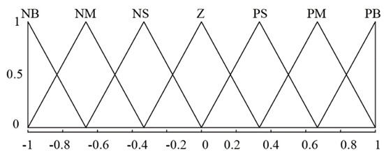
Figure 9.
Membership functions of the inputs.
Afterward, Mamdani-type fuzzy reasoning is used; the speed controller fuzzy rules table is shown in Table 1, where M, B, S, VB, and VS indicate moderate, large, small, extremely large, and extremely small, respectively.

Table 1.
Fuzzy rules base of speed controller.
The output rule of the fuzzy inference engine is
where and are the variable inputs and is the output of the ith fuzzy rule.
Then, during de-fuzzy processing, outputs of the fuzzy control algorithm are expressed as six linguistic variables: neutral (Z), extremely small (VS), small (S), moderate (M), large (B), and extremely large (VB). In this study, the triangle membership function with high sensitivity is applied to both and , as shown in Figure 10.
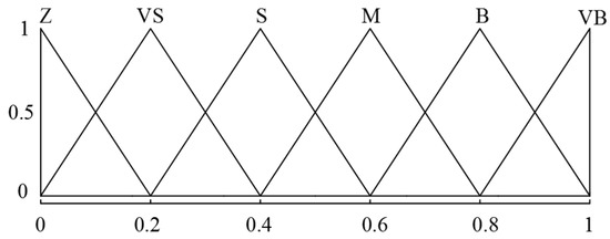
Figure 10.
Membership functions of the outputs.
The centroid defuzzification method is applied during fuzzy decoupling:
where and are the membership function values of and , respectively, and P is the number of fuzzy rules.
During the adjustment of the FLADRC-based speed controller fuzzy rules, many tests are conducted, which assure the best dynamic performance under different working conditions. Firstly, as shown in Table 1, the states of the system are divided into 49 sections according to the value of ev and . Secondly, an appropriate set of LADRC parameters is selected according to test results. After that, the value of is increased until the system starts to become unstable in each section, then the value of is increased until the system starts to become unstable as well. Finally, compromise between the two fuzzy parameters is made to achieve better dynamic performance.
3.4. Pressure Controller Design
As shown in Equation (1), the pressure of the inlet and outlet chambers can affect each other through external load, so pressure vibrations on one side will cause vibrations on the other side at the same time. These vibrations can significantly affect cylinder speed stability, so the pressure curves on both sides should be as smooth as possible. Under the influence of external load, frictional resistance, and inaccurate modeling parameters, a pressure controller based on fuzzy-LADRC is designed to reduce the pressure ripple of both inlet and outlet chambers. Since the inlet proportional flow control valve is used to control the cylinder speed, we chose an outlet flow control valve to control the back pressure of the cylinder.
According to Equation (8), first-order LADRC should be used to control boom cylinder chamber pressure. To overcome the existing contradiction between stability and rapidity, a fuzzy-LADRC algorithm was applied, as shown in Figure 11.

Figure 11.
Boom cylinder pressure control structure using FLADRC.
The control algorithm shown in Figure 11 is composed of three parts. The formula of the P controller is
where ep is the pressure tracking deviation, rp is the target chamber pressure, z1 is the observed cylinder chamber pressure value, up0 is the output value of the P controller, and kpp is the proportional gain of the P controller.
The expression of the extended state observer is
where z2 is the observed value of the additional state variable, b0 is a rough approximation of the system control gain, β1p and β2p are the observer parameters, and up is the final output value of the control algorithm. According to the concept of frequency scale, the value of β1p and β2p can be determined by observer bandwidth wop, as shown:
Finally, the equation for the remaining part can be expressed as
Combined with the fuzzy algorithm, wop in Equation (10) is modified as follows:
where is the amplification factor of observer bandwidth, which will be adjusted according to speed tracking deviation ep and its derivative . As with the speed controller expressed in Section 3.4, the inputs and output are characterized by the triangular membership function, as shown in Figure 9 and Figure 10. The fuzzy logic controller uses a Mamdani-type method while the centroid method is used for defuzzification. The fuzzy rules of kpp and are shown in Table 2.

Table 2.
Fuzzy rules base of chamber pressure controller.
4. Experiment Setup
4.1. Hydraulic System Retrofit
A truck-mounted concrete pump with a six-section boom was used for experimentation in this article, as shown in Figure 12a. Traditionally, the boom cylinders are controlled by a proportional directional valve located at the pump base. This results in a time delay, as compressed fluid is pumped through long pipes to the cylinders. To reduce this delay, IMVs as described in Figure 1 were mounted near the cylinders (e.g., near the boom section 1 cylinder), as shown in Figure 12b. By placing the IMVs close to the cylinders, the response time of the cylinders is significantly reduced, providing a solid foundation for the control algorithm design.
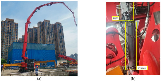
Figure 12.
Truck-mounted concrete pump: (a) Picture of truck-mounted concrete pump with six-section boom; (b) boom section 1 cylinder and its IMV.
4.2. Electronic Control System
A CAN bus was used to connect the electronic devices on the test rig, as shown in Figure 13. Operators used the joystick on the remote control to send speed control commands. The remote control communicated with the pump truck controller via Wi-Fi, allowing the controller to send boom movement speed commands via the CAN bus. An STM32 controller was used to receive speed commands and messages from the pressure and position sensors through analog input ports. The controller also sent calculated control current values to the corresponding coil drivers via the CAN bus.
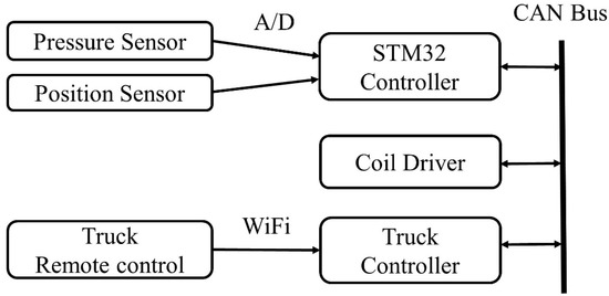
Figure 13.
Electronic control system of the test rig.
5. Experiment Results
Placing concrete accurately requires the movement of each boom section [44], so motion control of each boom section was tested. According to the knowledge of skilled operators, unfolding and folding in 180 degrees (90 degrees for boom section 1) is the most common working condition of boom sections on truck-mounted pumps. With this in mind, every boom section’s most common working condition was chosen as their basic experiment.
As discussed in section 2, cylinder #2, cylinder #3, and cylinder #5 have the same linkage mechanism structure, so to eliminate repeated experimentation only cylinder #2 was tested during the experiment. Meanwhile, to show the advantage of FLADRC, a traditional PID, which is the most-used control algorithm, was applied under the same working conditions. The trial and error method was used in adjusting the PID; with enough experiments, we thought the best performance was achieved.
Additionally, the PID parameters for each link are different, which were adjusted to achieve the best dynamic performance. Parameters in this paper were all selected according to experiment results.
5.1. Experiment with Boom Section 1
The movement of boom section 1 is depicted in Figure 14. The unfolding process involves a movement from 0 degrees to 90 degrees, with the vectors of external force and cylinder #1 speed in opposite directions. To maintain the stability of the chamber pressure in cylinder #1, it is recommended to set the target back pressure as low as possible. However, during the folding process, where the movement is from 90 degrees to 0 degrees, the vectors of external force and speed are in the same direction. In this case, the target back pressure should be set higher to maintain the stability of cylinder #1′s chamber pressure.
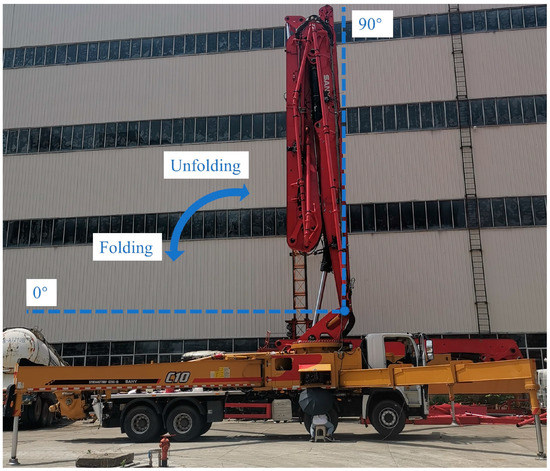
Figure 14.
Movement schematic of boom section 1.
According to relevant regulations, the target speed of cylinder #1 was set to 10 mm/s during the unfolding process and 14.5 mm/s during the folding process. The speed step response experiment results using the PID are shown in Figure 15 while the results using the LADRC are shown in Figure 16.
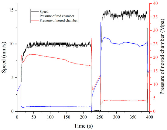
Figure 15.
Step response experiment results of cylinder #1 using PID.
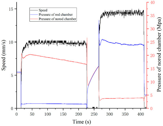
Figure 16.
Step response experiment results of cylinder #1 using FLADRC.
To make the comparison between PID and FLADRC more distinct, the speed error of cylinder #1 during the unfolding and folding process is shown in Figure 17 and Figure 18, respectively.

Figure 17.
Speed error of cylinder #1 during unfolding.

Figure 18.
Speed error of cylinder #1 during folding.
Startup time, which represents system rapidity, and fluctuation range, which relates to system stability, are the two parameters that operators are most concerned about. Thus, these two parameters were selected as the assessment indices of the control algorithm, as shown in Table 3.

Table 3.
Assessment indices of cylinder#1 motion control using PID and FLADRC.
For cylinder #1, the application of FLADRC resulted in a 34.4% reduction in the startup time of the unfolding process compared to the PID method. Additionally, the fluctuation range of cylinder #1’s folding motion using the FLADRC was 30.8% lower than when using the PID.
5.2. Experiment with Boom Section 2
During the unfolding process, boom section 2 moves from 0 degrees to 180 degrees, as shown in Figure 19. The vectors of external force applied on cylinder #2 and its speed are in opposite directions. Conversely, during the folding process, boom section 2 moves from 180 degrees to 0 degrees, and the vectors of external force applied on cylinder #2 and its speed are in the same direction. The back pressure setting standard of cylinder #2 was the same as that of cylinder #1.
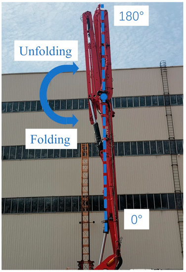
Figure 19.
Movement schematic of boom section 2.
Based on relevant regulations, cylinder #2’s speed target was set as 10 mm/s during the unfolding process and at 14 mm/s during the folding process. Step response experiment results are shown in Figure 20 and Figure 21.
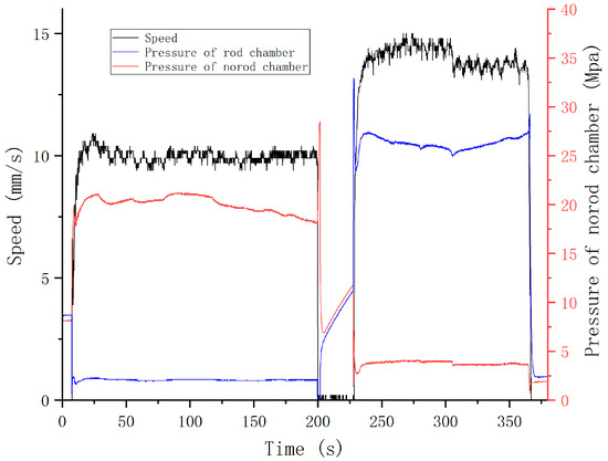
Figure 20.
Step response experiment results of cylinder #2 using PID.
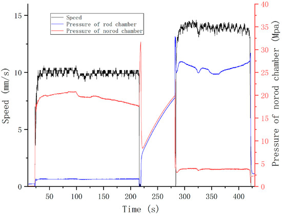
Figure 21.
Step response experiment results of cylinder #2 using FLADRC.
The speed error of cylinder #2 during the unfolding and folding processes using PID and FLADRC is shown in Figure 22 and Figure 23.

Figure 22.
Speed error of cylinder #2 during unfolding.

Figure 23.
Speed error of cylinder #2 during folding.
The startup time and fluctuation range of the different control algorithms are shown in Table 4.

Table 4.
Assessment indices of cylinder #2 motion control using PID and FLADRC.
For cylinder #2, when the FLADRC was applied, the fluctuation range of the unfolding process was shortened by 10% compared with that using the PID, while both the startup time and fluctuation range of cylinder #2’s folding motion using the FLADRC was 42.6% and 27.1% less than that using the PID, respectively.
5.3. Experiment with Boom Section 4
The range of motion as well as vectors of external force and speed during the unfolding and folding processes of cylinder #4 were same as cylinder #2, so the back pressure setting standard of cylinder #4 was same as cylinder #2, as shown in Figure 24.
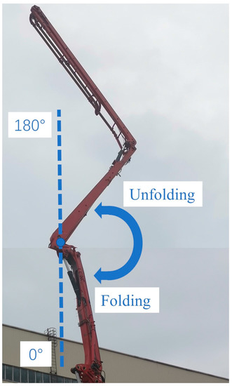
Figure 24.
Movement schematic of boom section 4.
Based on relevant regulations, cylinder #4’s speed target was set as 10 mm/s during the unfolding process and 10 mm/s during the folding process. The step response experiment results are shown in Figure 25 and Figure 26.
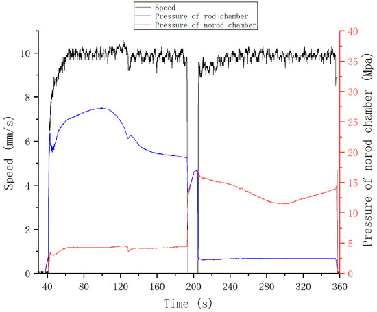
Figure 25.
Step response experiment results of cylinder #4 using PID.
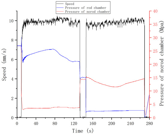
Figure 26.
Step response experiment results of cylinder #4 using FLADRC.
The speed error of cylinder #4 during the unfolding and folding processes using PID and FLADRC is shown in Figure 27 and Figure 28.

Figure 27.
Speed error of cylinder #4 during unfolding.

Figure 28.
Speed error of cylinder #4 during folding.
The startup time and fluctuation range of the different control algorithms are shown in Table 5.

Table 5.
Assessment indices of cylinder #4 motion control using PID and FLADRC.
For cylinder #4, when the FLADRC was applied, both the startup time and fluctuation range of the unfolding process was shortened by 66.7% and 41.7% compared with using the PID, respectively, while the fluctuation range of cylinder #2’s folding motion using the FLADRC was 15.4% less than that using the PID.
5.4. Experiment with Boom Section 6
The range of motion, vectors of external force, and speed during the unfolding and folding processes of cylinder #6 were the same as those of cylinder #2. As a result, the back pressure setting standard of cylinder #6 was the same as that of cylinder #2, as depicted in Figure 29.
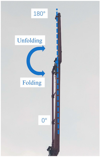
Figure 29.
Movement schematic of boom section 6.
As per relevant regulations, the speed target for cylinder #6 was set at 13 mm/s during the unfolding process and 13 mm/s during the folding process. The step response experiment results are shown in Figure 30 and Figure 31.
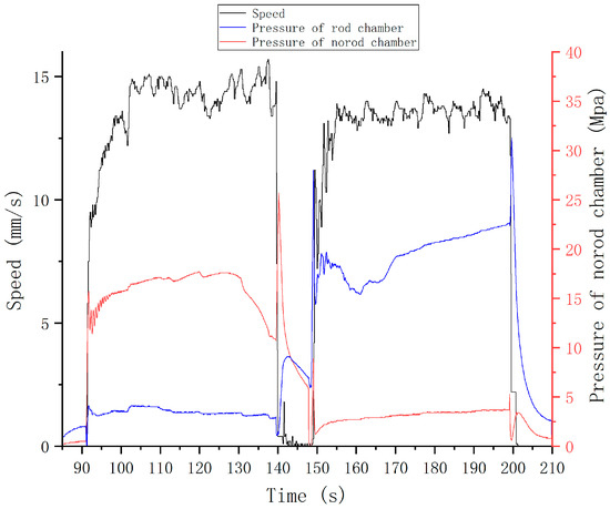
Figure 30.
Step response experiment results of cylinder #6 using PID.
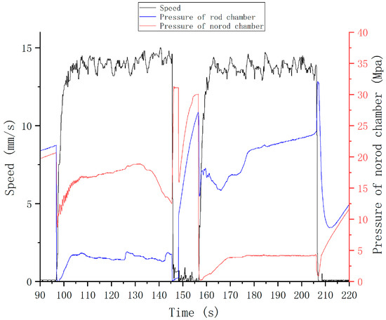
Figure 31.
Step response experiment results of cylinder #6 using FLADRC.
The speed error of cylinder #6 during the unfolding and folding processes using PID and FLADRC are shown in Figure 32 and Figure 33.

Figure 32.
Speed error of cylinder #6 during unfolding.

Figure 33.
Speed error of cylinder #6 during folding.
The startup time and fluctuation range of the different control algorithms are shown in Table 6.

Table 6.
Assessment indices of cylinder #6 motion control using PID and FLADRC.
For cylinder#6, the application of the FLADRC resulted in a 40.3% reduction in the startup time and a 20.1% reduction in the fluctuation range of the unfolding process compared to the PID method. Meanwhile, the fluctuation range of cylinder #2’s folding motion using the FLADRC was 10.9% lower than when using the PID.
6. Discussion
According to the system state space Equation (8), the speed of the cylinder can be affected by various parameters that change under different working conditions, such as the equivalent mass mp, equivalent damping coefficient cp, and rod external load FL. The FLADRC algorithm proposed in this paper can effectively eliminate the influence of both the external disturbance of the cylinder system and internal parameter uncertainty, resulting in better cylinder speed control performance and easing the contradiction between stability and rapidity. When the FLADRC algorithm is applied, at least one parameter in the startup time and fluctuation range can be improved compared to the PID algorithm, with an improvement range of 10% to 66.7% under different working conditions.
7. Conclusions
This paper presents the use of four cartridge valves to replace the traditional proportional directional spool valve in controlling the motion of truck-mounted concrete pump boom cylinders. Additionally, the FLADRC strategy was proposed to improve stability and rapidity in the presence of uncertain model parameters and external loads.
Mathematical modeling and experiments were conducted to verify the effectiveness of the FLADRC. When the FLADRC was applied, the motion fluctuation range of cylinders #2, #4, and #6 during the unfolding and folding processes and the motion fluctuation range of cylinder #1 during the folding process were smaller compared with using a PID. Because of more steady external forces, the fluctuation range of cylinder #1 during the unfolding process was not significantly improved by FLADRC. The startup time of cylinders #1, #4, and #6 during unfolding and cylinder #2 during folding were smaller compared with that when using PID due to the over-running load; startup time under other working conditions was not shortened by using the FLADRC.
The results show the superiority of FLADRC during the unfolding and folding of different boom sections. Multi-linkage joint control will be studied in our future works.
Author Contributions
Conceptualization, H.B. and H.H.; writing—original draft preparation, H.B.; writing—review and editing, D.H. and B.Z.; supervision, Q.Z. and H.H.; funding acquisition, B.Z. and H.Y. All authors have read and agreed to the published version of the manuscript.
Funding
This research was funded by the Ministry of Industry and Information Technology, grant number 174-TC220H064.
Data Availability Statement
Not applicable.
Acknowledgments
We acknowledge the support given by the Binhai Industrial Technology Research Institute of Zhejiang University.
Conflicts of Interest
The authors declare no conflict of interest.
References
- Nariman, N.A. Sensitivity Indices of a Reinforced Concrete Beam Exposed to Explosions. Int. J. Hydromechatronics 2022, 5, 92–108. [Google Scholar] [CrossRef]
- Weber, J. Independent Metering Systems. Int. J. Hydromechatronics 2018, 1, 91–106. [Google Scholar] [CrossRef]
- Eriksson, B.; Palmberg, J.-O. Individual Metering Fluid Power Systems: Challenges and Opportunities. Proc. Inst. Mech. Eng. Part I J. Syst. Control Eng. 2011, 225, 196–211. [Google Scholar] [CrossRef]
- Hu, H.; Zhang, Q. Realization of Programmable Control Using a Set of Individually Controlled Electrohydraulic Valves. Int. J. Fluid Power 2002, 3, 29–34. [Google Scholar] [CrossRef]
- Hu, H.; Zhang, Q. Multi-Function Realization Using an Integrated Programmable E/H Control Valve. Appl. Eng. Agric. 2003, 19, 283. [Google Scholar] [CrossRef]
- Yao, B.; DeBoer, C. Energy-Saving Adaptive Robust Motion Control of Single-Rod Hydraulic Cylinders with Programmable Valves. In Proceedings of the 2002 American Control Conference (IEEE Cat. No.CH37301), Anchorage, AK, USA, 8–10 May 2002; IEEE: Anchorage, AK, USA, 2002; Volume 6, pp. 4819–4824. [Google Scholar]
- Yao, B.; Liu, S. Energy-Saving Control of Hydraulic Systems with Novel Programmable Valves. In Proceedings of the 4th World Congress on Intelligent Control and Automation (Cat. No.02EX527), Shanghai, China, 10–14 June 2002; IEEE: Shanghai, China, 2002; Volume 4, pp. 3219–3223. [Google Scholar]
- Liu, S.; Yao, B. Coordinate Control of Energy Saving Programmable Valves. IEEE Trans. Contr. Syst. Technol. 2008, 16, 34–45. [Google Scholar] [CrossRef]
- Lu, L.; Yao, B.; Liu, Z. Energy Saving Control of a Hydraulic Manipulator Using Five Cartridge Valves and One Accumulator. IFAC Proc. Vol. 2013, 46, 84–90. [Google Scholar] [CrossRef]
- Lu, L.; Yao, B. Energy-Saving Adaptive Robust Control of a Hydraulic Manipulator Using Five Cartridge Valves with an Accumulator. IEEE Trans. Ind. Electron. 2014, 61, 7046–7054. [Google Scholar] [CrossRef]
- Shenouda, A. Quasi-Static Hydraulic Control Systems and Energy Savings Potential Using Independent Metering Four-Valve Assembly Configuration; Georgia Institute of Technology: Atlanta, GA, USA, 2006. [Google Scholar]
- Shenouda, A.; Book, W. Energy Saving Analysis Using a Four-Valve Independent Metering Configuration Controlling a Hydraulic Cylinder; SAE International: Warrendale, PA, USA, 2005. [Google Scholar]
- Shenouda, A.; Book, W. Optimal Mode Switching for a Hydraulic Actuator Controlled With Four-Valve Independent Metering Configuration. Int. J. Fluid Power 2008, 9, 35–43. [Google Scholar] [CrossRef]
- Ghini, Y.; Vacca, A. A Method to Perform Prognostics in Electro-Hydraulic Machines: The Case of an Independent Metering Controlled Hydraulic Crane. Int. J. Hydromechatronics 2018, 1, 197–221. [Google Scholar] [CrossRef]
- Choi, K.; Seo, J.; Nam, Y.; Kim, K.U. Energy-Saving in Excavators with Application of Independent Metering Valve. J. Mech. Sci. Technol. 2015, 29, 387–395. [Google Scholar] [CrossRef]
- Lee, J.-C.; Jin, K.-C.; Kwon, Y.-M.; Choi, L.-G.; Choi, J.-Y.; Lee, B.-K. Development of the Independent Metering Valve Control System and Analysis of Its Performance for an Excavator. In Proceedings of the BATH/ASME 2016 Symposium on Fluid Power and Motion Control, Bath, UK, 7–9 September 2016; American Society of Mechanical Engineers: New York, NY, USA, 2016; p. V001T01A021. [Google Scholar]
- Liu, K.; Gao, Y.; Tu, Z.; Lin, P. Energy-Saving Analysis of the Independent Metering System with Pressure Compensation for Excavator’s Manipulator. Proc. Inst. Mech. Eng. Part I J. Syst. Control Eng. 2016, 230, 905–920. [Google Scholar] [CrossRef]
- Vukovic, M.; Murrenhoff, H. The Next Generation of Fluid Power Systems. Procedia Eng. 2015, 106, 2–7. [Google Scholar] [CrossRef]
- Linjama, M.; Vilenius, M. Energy-efficient motion control of a digital hydraulic joint actuator. Proc. JFPS Int. Symp. Fluid Power 2005, 2005, 640–645. [Google Scholar] [CrossRef]
- Han, J. From PID to Active Disturbance Rejection Control. IEEE Trans. Ind. Electron. 2009, 56, 900–906. [Google Scholar] [CrossRef]
- Gao, B.; Shao, J.; Yang, X. A Compound Control Strategy Combining Velocity Compensation with ADRC of Electro-Hydraulic Position Servo Control System. ISA Trans. 2014, 53, 1910–1918. [Google Scholar] [CrossRef] [PubMed]
- Liu, C.; Luo, G.; Chen, Z.; Tu, W.; Qiu, C. A Linear ADRC-Based Robust High-Dynamic Double-Loop Servo System for Aircraft Electro-Mechanical Actuators. Chin. J. Aeronaut. 2019, 32, 2174–2187. [Google Scholar] [CrossRef]
- Fan, Y.; Shao, J.; Sun, G.; Shao, X. Active Disturbance Rejection Control Design Using the Optimization Algorithm for a Hydraulic Quadruped Robot. Comput. Intell. Neurosci. 2021, 2021, e6683584. [Google Scholar] [CrossRef]
- Li, Z.; Ma, X.; Li, Y.; Meng, Q.; Li, J. ADRC-ESMPC Active Heave Compensation Control Strategy for Offshore Cranes. Ships Offshore Struct. 2020, 15, 1098–1106. [Google Scholar] [CrossRef]
- Xun, W.Q.; Yu, Z.K.; Dong, D.X. An Exoskeleton Joint Output Force Control Technology Based on Improved ADRC. In Proceedings of the 2017 2nd International Conference on Robotics and Automation Engineering (ICRAE), Shanghai, China, 29–31 December 2017; pp. 146–150. [Google Scholar]
- Miao, J.; Yao, X.; Zhang, J.; Yang, S. Application of ADRC in Hydraulic AGC System. In Proceedings of the 33rd Chinese Control Conference, Nanjing, China, 28–30 July 2014; pp. 6283–6286. [Google Scholar]
- Shi, M.; Liu, X.; Shi, Y.; Chen, W.; Zhao, Q. Research on the Sliding Mode Based ADRC for Hydraulic Active Suspension of a Six-Wheel off-Road Vehicle. In Proceedings of the 2011 International Conference on Electronic Mechanical Engineering and Information Technology, Harbin, China, 12–14 August 2011; Volume 2, pp. 1066–1069. [Google Scholar]
- Shi, M.; Liu, X.; Shi, Y. Research n Enhanced ADRC Algorithm for Hydraulic Active Suspension. In Proceedings of the 2011 International Conference on Transportation, Mechanical, and Electrical Engineering (TMEE), Changchun, China, 16–18 December 2011; pp. 1539–1543. [Google Scholar]
- Chen, H.; Qi, X.; Chen, J.; Fu, Y. Research on Anti-Control of Missile Electro-Hydraulic Actuator Using Active Disturbance Rejection Control Method. In Proceedings of the 2009 Fourth International Conference on Innovative Computing, Information and Control (ICICIC), Kaohsiung, Taiwan, 7–9 December 2009; pp. 1443–1446. [Google Scholar]
- Gao, Z. Scaling and Bandwidth-Parameterization Based Controller-Tuning”, to Be Presented at the 2003 American Control Conference. In Proceedings of the American Control Conference, Denver, CO, USA, 4 June 2003; pp. 4–6. [Google Scholar]
- Wang, C.; Quan, L.; Zhang, S.; Meng, H.; Lan, Y. Reduced-Order Model Based Active Disturbance Rejection Control of Hydraulic Servo System with Singular Value Perturbation Theory. ISA Trans. 2017, 67, 455–465. [Google Scholar] [CrossRef]
- Huang, J.; Cen, Y. Research on Variable Mass Control of Series Manipulator Based on Linear Active Disturbance Rejection Control. Meas. Control 2020, 53, 1194–1202. [Google Scholar] [CrossRef]
- Wang, L.; Zhao, D.; Zhang, Z.; Liu, Q.; Meng, F. Linear Active Disturbance Rejection Control for Hydraulic Position Servo System. In Proceedings of the 2020 39th Chinese Control Conference (CCC), Shenyang, China, 27–29 July 2020; pp. 2522–2527. [Google Scholar]
- Jin, K.; Song, J.; Li, Y.; Zhang, Z.; Zhou, H.; Chang, X. Linear Active Disturbance Rejection Control for the Electro-Hydraulic Position Servo System. Sci. Prog. 2021, 104, 00368504211000907. [Google Scholar] [CrossRef]
- Liu, F.; Yang, Y.; Wang, L. Active Disturbance Rejection Control Design for the Hydraulic Actuator on Weeding Machine. In Proceedings of the 2021 40th Chinese Control Conference (CCC), Shanghai, China, 26-28 July 2021; pp. 3822–3827. [Google Scholar]
- Zhou, X.; Cui, Y.; Ma, Y. Fuzzy Linear Active Disturbance Rejection Control of Injection Hybrid Active Power Filter for Medium and High Voltage Distribution Network. IEEE Access 2021, 9, 8421–8432. [Google Scholar] [CrossRef]
- Sun, C.; Liu, M.; Liu, C.; Feng, X.; Wu, H. An Industrial Quadrotor UAV Control Method Based on Fuzzy Adaptive Linear Active Disturbance Rejection Control. Electronics 2021, 10, 376. [Google Scholar] [CrossRef]
- Sun, C.; Liu, C.; Feng, X.; Jiao, X. Visual Servoing of Flying Robot Based on Fuzzy Adaptive Linear Active Disturbance Rejection Control. IEEE Trans. Circuits Syst. II Express Briefs 2021, 68, 2558–2562. [Google Scholar] [CrossRef]
- Zhang, F.; Hou, J.; Ning, D.; Gong, Y. Depth Control of an Oil Bladder Type Deep-Sea AUV Based on Fuzzy Adaptive Linear Active Disturbance Rejection Control. Machines 2022, 10, 163. [Google Scholar] [CrossRef]
- Han, D.; Li, C.; Shi, Z. Attitude Autopilot Design Based on Fuzzy Linear Active Disturbance Rejection Control. Aerospace 2022, 9, 429. [Google Scholar] [CrossRef]
- Feng, X.; Xie, S.; Zhang, Z.; Chen, Y.; Qin, H.; Zhao, C. Research on Speed Loop Control of IPMSM Based on Fuzzy Linear Active Disturbance Rejection Control. Energy Rep. 2022, 8, 804–812. [Google Scholar] [CrossRef]
- Qin, Y.; Yang, J.; Guo, H.; Wang, Y. Fuzzy Linear Active Disturbance Rejection Control Method for Permanent Magnet Electromagnetic Hybrid Suspension Platform. Appl. Sci. 2023, 13, 2631. [Google Scholar] [CrossRef]
- Danes, L.; Vacca, A. A Frequency Domain-Based Study for Fluid-Borne Noise Reduction in Hydraulic System with Simple Passive Elements. Int. J. Hydromechatronics 2021, 4, 203–229. [Google Scholar] [CrossRef]
- Xie, M.; Zhu, C.; Xie, X. Visual Tracking Control of SCARA Robot System Based on Deep Learning and Kalman Prediction Method. Int. J. Hydromechatronics 2022, 4, 384–396. [Google Scholar] [CrossRef]
Disclaimer/Publisher’s Note: The statements, opinions and data contained in all publications are solely those of the individual author(s) and contributor(s) and not of MDPI and/or the editor(s). MDPI and/or the editor(s) disclaim responsibility for any injury to people or property resulting from any ideas, methods, instructions or products referred to in the content. |
© 2023 by the authors. Licensee MDPI, Basel, Switzerland. This article is an open access article distributed under the terms and conditions of the Creative Commons Attribution (CC BY) license (https://creativecommons.org/licenses/by/4.0/).