Review

Strain Characteristics of PLZT-Based Ceramics for Actuator Applications

by
Apichart Limpichaipanit
and
Athipong Ngamjarurojana
*
Department of Physics and Materials Science, Faculty of Science, Chiang Mai University, Chiang Mai 50200, Thailand
*
Author to whom correspondence should be addressed.
Actuators 2023, 12(2), 74; https://doi.org/10.3390/act12020074
Submission received: 26 December 2022 / Revised: 26 January 2023 / Accepted: 8 February 2023 / Published: 9 February 2023

Abstract

:
Lead lanthanum zirconate titanate (PLZT) ceramics exhibit excellent dielectric, ferroelectric and piezoelectric properties, and they can be used in many applications, including actuators. In this review, the processing and properties of PLZT-based ceramics will be the main focus of the first part. An introduction to PLZT ceramics is given and the methods to improve processing of PLZT-based ceramics are explained in terms of the addition of sintering aids, fabrication in the form of composites, and the application of dopants. The second part will be related to strain measurement to investigate converse piezoelectric properties (actuating effect). Strain measurement techniques by Michelson interferometry and case studies in PLZT-based ceramics (aging effect, temperature dependence and magnetic field effect) are included.

1. Introduction

Lead lanthanum zirconate titanate, or PLZT ceramics, were first developed in the 1960s for electro-optic applications. Possible optical devices are waveguides (due to high transparency), shutters and filters (controlled by an applied voltage), depending on the composition of PLZT ceramics [1]. Piezoelectric applications include transducers (utilization of phase transition between the ferroelectric and non-ferroelectric phase) and actuators (from the slim hysteresis loop) [2]. PLZT ceramics are considered as photostrictive actuators based on piezoelectric properties where the light-driven process involves photovoltaic effect (light generates voltage across the material) followed by converse piezoelectric effect (generated voltage causes positive (extension) or negative (contraction) strain in the material) [3]. The comprehensive papers by Prof. Uchino and his co-workers [4,5] show the extensive and systematic study of PLZT ceramics with various compositions for the applications of photostrictive actuators. They found that the suitable composition around the morphotropic phase boundary (MPB) yielded the maximum photocurrent and photovoltage. Moreover, the addition of tungsten oxide (WO3) as dopant in PLZT ceramics could also improve photostrictive properties, and actuator applications were possible in the form of both bulk ceramic samples and thin films. Recently, the investigation of photostrictive properties in PLZT ceramics was revisited [6]. Raman spectroscopy results suggested that photo-induced actuating effect occurred due to structural change caused by the oxygen bonds between zirconium and titanium, and the effect was strong enough to produce the strain contributing to shape change of PLZT ceramics.
Recent work demonstrates that PLZT ceramics benefit from dielectric, ferroelectric, and piezoelectric properties and make the applications of advanced materials possible. Li et al. [7] reported high energy storage density capacitor with the efficiency of 70% in bulk antiferroelectric PLZT resulting from electric field-induced phase transition and low loss of slim hysteresis behavior. Light controlled actuators based on PLZT ceramics were fabricated by Liu et al. [8]. They designed a micro actuator with PLZT electrodes connected to a driven component (torsion beam). UV irradiation resulted in the generation of photovoltage in the PLZT electrodes, and the electrostatic moment responsible for torsion bending was created in the driven component. Fast response speed and control of deformation could be achieved accurately. The design of micro actuators based on PLZT electrodes has been further developed using a mathematical model [9], which suggests feasible actuator applications with a high accuracy of displacement control. The meticulous study of actuator applications based on PLZT ceramics as light-operated microgrippers with the size 1.3 mm × 0.7 mm × 1.027 mm (as holder for specimens with dimensions up to 1000 μm) was carried out by Huang et al. [10]. In this work, mathematical modelling was applied to investigate the relationship between light intensity, incidence time and displacement to control the operation and to determine the optimized design as well as the working condition. Experimental results revealed that on-off control during operation could be performed but further study is required to improve the response for the release of the microgripper, which is slow due to the residual photovoltage.
Many processing routes have been attempted to fabricate the ceramic samples. To ensure homogeneous distribution of composition, the chemical route is introduced during powder processing. Hot press sintering is applied to obtain dense ceramic with equiaxial grain growth (~2–5 μm) [1]. Not only PLZT ceramics exhibit excellent electro-optic properties, they also show promising piezoelectric properties as PZT-based ceramics with lanthanum (La) as a soft dopant. The development of PLZT-based ceramics has been the area of interest in electroceramics. The methods to improve microstructure and properties include the introduction of a novel processing route, the optimization of processing conditions and the addition of sintering aids or dopants [11]. Research work in past decades has demonstrated that sintering aids are effective to produce ceramic samples with dense microstructure from the benefit of a glassy phase formed during sintering. The addition of second phase reinforcement that possesses electrical properties can tailor PLZT-based ceramics in terms of both microstructure and properties. The most common method is doping [12] where a small amount of dopant(s) is incorporated into PLZT ceramics to substitute some cations to tune electrical properties. Overall, the first part of the review is given in the topic of processing and properties of PLZT-based ceramics, consisting of three main sections, namely PLZT ceramics (to introduce the basic knowledge of PLZT including the crystal structure, phase diagram and relaxor behavior), grain boundary complexions and pore structure (to describe the concept of grain boundary chemistry and porosity in relation to electrical properties), and tailoring microstructure and properties of PLZT ceramics (to explain three methods, which are utilization of sintering aids, fabrication in the form of composites and addition of dopant).
The study of piezoelectric properties of bulk ceramics requires suitable methods of strain measurement. Nowadays, up-to-date technologies offer state-of-art measurement methods with high precision. Development of metrology and optics is the key point for the improvement of strain measurement techniques (better resolution and more accurate measurement). The second part of the review starts with Michelson interferometry, which is considered as the useful technique employed to detect a small change of displacement which can be applied to strain measurement [13]. Sample preparation and equipment setting are also important to obtain valid results from the measurement and this review provides the information of sample holders for three measurement methods (standard measurement to investigate frequency dependence, varied temperatures to investigate temperature dependence, and external magnetic field to investigate magnetoelectric effect). Case studies of strain measurement in PLZT-based ceramics are also included. There are three parts, namely, aging effect (time-dependent effect), temperature dependence, and external magnetic field effect. The review ends with concluding remarks to summarize and offer some insights to develop PLZT-based ceramics for actuator applications in the future.

2. Processing and Properties of PLZT-Based Ceramics
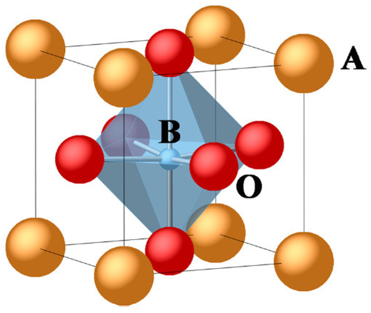
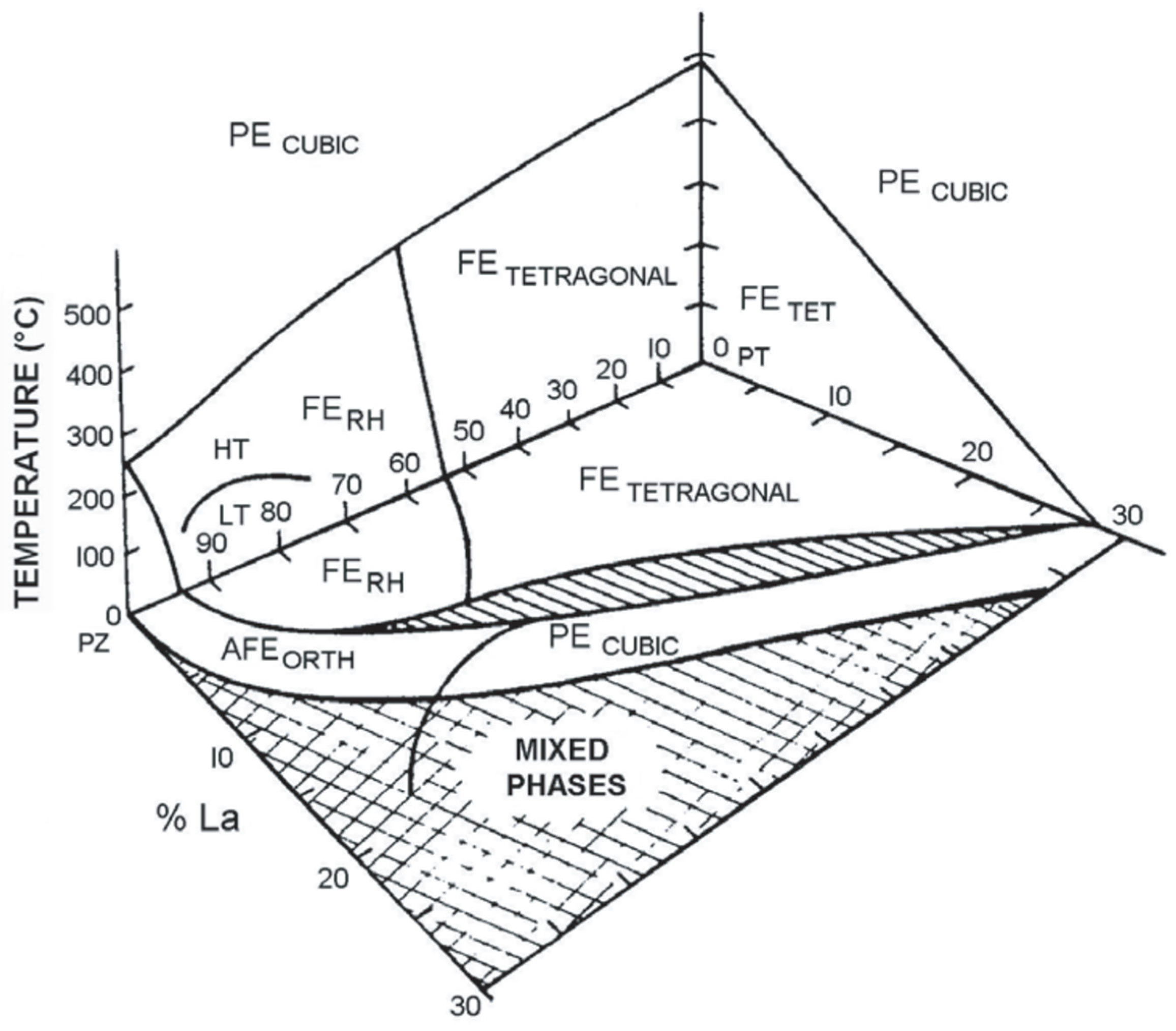
The knowledge of materials science and technology has offered endless possibilities and methods to improve dielectric, ferroelectric, and piezoelectric properties of ceramic materials. Development of some new ceramic systems, especially lead-free components, has become of concern in the field of electroceramics due to health and environmental issues. Rödel and Li [14] wrote a short review to share their insightful thoughts of lead-free piezoceramics categorized into four main groups, namely bismuth-based, alkaline niobium-based, barium titanate-based and bismuth ferrite-based ceramics. Extensive review articles and books are available to explain the mechanisms that contribute to the enhancement of lead-free dielectric, ferroelectric and piezoelectric ceramics. For example, the book by Acosta [15] elucidates strain mechanisms in BCZT (barium calcium zirconate titanate) and BNT (bismuth sodium titanate)-based ceramics in detail. In this article, however, we will focus on lead-based ceramics (lead lanthanum zirconate titanate or PLZT in particular) as there has been also some progress in recent years. An introduction to PLZT ceramics is included in the first part of this section to explain the concepts in terms of structure and properties.
Apart from developing new ceramic materials, processing also plays a crucial role to ensure desirable microstructure and therefore properties. Technologies regarding to ceramic processing in recent years allow us to fabricate electroceramics with significantly lower temperature and in shorter time. Cold sintering process (CSP) is the most recent technique to fabricate ceramics at temperatures below 200 °C and the successful work by Baker et al. [16], where Li2MoO4 capacitors with the thickness of ~20 μm as a single layer could be printed on PET film for the first time, demonstrates an opportunity to utilize CSP for ceramic processing in the future. However, it is worth noting that typical ceramic microstructure contains grain boundaries and pores in polycrystalline ceramics. The second part of this section is then devoted to the specific region of grain boundaries called grain boundary complexions and pore structure to understand the structure-property relation of electroceramics.
In addition, conventional ceramic processing can still be employed to obtain electroceramics with enhanced properties but optimal processing parameters such as sintering temperature and soaking time are required [17]. Tailoring microstructure of electroceramics can also be achieved by the addition of sintering aid to introduce a liquid phase to improve densification and then properties. An alternative method is to fabricate ceramic composites where the microstructure and properties of electroceramics can be tuned by the composition and amount of the second phase or reinforcement. The addition of dopants is the other possibility (and perhaps the easiest way) to control ceramic microstructure and electrical properties by defect chemistry. The last part of this section contributes to tuning microstructure and properties of electroceramics by sintering aids, composites, and dopants.

2.1. PLZT Ceramics

Lead lanthanum zirconate titanate (PLZT) or La-doped PZT can be written in chemical formula as Pb1−xLax(ZryTi1−y)1−x/4O3 where x is the molar fraction of lanthanum and y is the molar fraction of zirconia. It can be denoted by PLZT x’/y’/100-y’ where x’ is the mole percent of lanthanum and y’ is the mole percent of zirconia. PLZT has perovskite structure ABO3 where the A-site contains Pb2+ or La3+ ions and the B-site contains Zr4+ or Ti4+ ions as shown in Figure 1. Pb2+ ions are partially substituted by La3+ ions. Different amounts of La and Zr/Ti ratio results in PLZT ceramics with different crystal structure and ferroelectric properties.
Figure 2 presents the phase diagram of PLZT ceramic system. It can be seen that PLZT solid solution exhibits paraelectric (PE), ferroelectric (FE) and antiferroelectric (AFE) phases depending on the composition and crystal structure. The line between tetragonal and rhombohedral (RH) is called the morphotropic phase boundary (MPB). The composition in PLZT ceramic close to the MPB region contains PLZT 8/65/35, 9/65/35 and 12/40/60 whereas ferroelectric tetragonal and rhombohedral composition is PLZT 8/40/60 and 9/70/30, respectively. Antiferroelectric composition usually consists of low lanthanum and high zirconia content such as PLZT 2/90/10 [11].
It is generally acknowledged that the composition near MPB gives rise to excellent dielectric, ferroelectric and piezoelectric properties due to the mixed phase of tetragonal and rhombohedral crystal structure. Hinterstein et al. [20] carried out synchrotron X-ray diffraction to explain the relationship between the structure and properties of lead zirconate titanate (PZT) at MPB and the results supported the existence of a monoclinic phase, which was also recently reported in PLZT by Kumar et al. [21]. Further investigation of strain mechanism of PZT at MPB by Hinterstein et al. [22] demonstrated that the crystal structure mainly contributed to strain in terms of domain switching and phase transition induced by an applied electric field, as later confirmed in PLZT by Somwan et al. [23].
One of the most interesting behaviors observed in PLZT in the vicinity of MPB is dielectric relaxor, which is caused by the disordered structure of (Pb,La) at A-site and (Zr,Ti) at B-site. Dielectric relaxor in PLZT has the main features including a broad dielectric peak (compared to sharp dielectric peak in normal ferroelectric), and shift of maximum dielectric peak to higher temperature and lower intensity when the frequency is increased (dispersion). Broad and diffuse peak results from the formation of polar nanoregions (PNRs) of the size of tens nanometer by short range order of the crystal structure [24]. In addition, hysteresis polarization and electric field (P-E) loop of relaxor materials is very slim because the remnant polarization (Pr) of nanodomain is very small [25]. The study of relaxor behavior as a function of temperature in PLZT is available elsewhere [26,27].

2.2. Grain Boundary Complexions and Pore Structure

Typical polycrystalline ceramic microstructure consists of grains, grain boundaries and pores. The main interest is focused on bulk properties (related to grains) but the properties contributed from grain boundaries should not be neglected. Grain boundaries are regarded as internal interfaces between different crystal orientation of grains. In electroceramics, grain boundaries serve many functions, i.e., space charge effect, formation of a depleted layer, charged defect mobility and mass transport by diffusion [28]. To explain electrical properties of polycrystalline ceramics, brick-wall model (where well aligned bricks represent grains, and gaps between bricks represent grain boundaries) and equivalent circuit (each component is considered as a resistor and a capacitor connected in parallel) are applied with the knowledge of defect chemistry at grain boundaries [29].
The study of grain boundaries is therefore crucial to better understand structure-property relation in ceramic materials. Thanks to the recent technologies in material characterization (especially electron microscopy), the details of grain boundaries are unveiled with the information of chemical composition. Combined with a thermodynamic approach, the term “grain boundary complexion” has been used to explain interfacial material in equilibrium with its abutting phases. The overview article by Cantwell et al. [30] briefly suggested that grain boundary complexion was responsible for the change of conduction in ion-conducting electrolytes and the enhancement of better discharge rate in a lithium ion battery with lithium phosphate-based films. Recently, Bowman et al. [31] demonstrated that the grain boundary composition affected the grain boundary conductivity even though the microstructure and grain orientation remained the same.
Porosity in ceramic materials is also a crucial factor that affects properties. Pores or voids are considered as three-dimensional defects whereas grain boundaries are sometimes considered as planar defects in ceramics. The effect of porosity to electrical properties of electroceramics has been investigated by several researchers. Okazaki and Nagata [32] reported deterioration of piezoelectric properties in PLZT ceramics (grain size of 1.5–2.0 μm) as the percentage of porosity increased and the main reason was the decrease in the space-charge electric field. Jiang and Cross [33] found that porosity affected electrical properties and accelerated fatigue aging in PZT and PLZT ceramics. Curecheriu et al. [34] studied the effect of porosity in BZT ceramics; they reported the decrease in dielectric constant by 40% when the porosity was 21%. Higher porosity can also shift Curie point to a higher temperature due to internal stress in ceramic samples [35]. The effect of porosity on the polarization-field response of ferroelectric materials was studied by Zhang et al. [36]. BCZT ceramics with porosity up to 40 vol% were fabricated and the mechanisms of broad electric field distribution (high porosity) and increase in matrix compliance (low porosity) were proposed to explain the change of ferroelectric behavior in terms of coercive field and remnant polarization. Overall, it is worth further investigating the defect chemistry of grain boundaries and pore structure in electroceramic materials to obtain the holistic view of the relationship between microstructure and properties in the future.

2.3. Tailoring Microstructure and Properties of PLZT Ceramics

2.3.1. Sintering Aids

Liquid phase sintering can be carried out by the addition of sintering aids. During firing, densification is accelerated to obtain ceramic samples with high density, which would then enhance electrical properties. Previous work by Liang et al. [37] showed that LiBiO2 could be utilized as a sintering aid to reduce the sintering temperature of PLZT to 900 °C, and the sample had improved dielectric and electrostrictive properties. Lead-based oxides such as Pb(W0.5Cu0.5)O3 [38] and PbO/CuO [39] could promote densification with grain growth and enhancement of dielectric and piezoelectric properties of PLZT.
The concept of glass ceramics, where the amount of liquid or glassy phase is large, to produce fully dense ceramics during vitrification upon cooling. Moreover, the careful control of cooling rate can produce a desirable crystallite phase in some perovskite glass ceramics as summarized in review by Yadav and Gautam [40]. Barium titanate (BaTiO3 or BT)-based ceramics could benefit from borosilicate glass as Hu et al. [41] reported the effect of glass addition to the stability of dielectric behavior and energy storage capacity of BaTiO3-Bi(Mg1/2Ti1/2)O3 ceramics. Khalf and Hall [42] used barium borosilicate glass to improve the densification of (Ba,Ca)(Zr,Ti)O3 lead-free ceramics where phase transition temperature increased and dielectric constant decreased. The glass ceramic was suitable for dielectric energy storage applications. Recent work by Li et al. [43] explored the application of BaO-B2O3-Bi2O3 glasses to aid the sintering of BT ceramics. The results revealed that the addition of 30% glass could significantly reduce the sintering temperature of BT from 1300 °C to 800 °C without the formation of any second phase. The relative density was increased, which directly increased dielectric constant (and indirectly by the polarizability of Bi3+ in the glass). Furthermore, ferroelectric properties could be enhanced provided that the ferroelectric phase of BaBi4Ti4O15 could be crystallized in the glass ceramics.

2.3.2. Composites

Electrical properties of electroceramics can be enhanced by means of compositing two or more ceramics to optimize microstructure and properties. The concept of a mixed phase in morphotropic phase boundary (MPB) can be applied to fabricate composites from each phase with different crystal structure to imitate MPB. In some cases, the second phase or reinforcement is added to the matrix to introduce an additional property, which is the characteristic of reinforcement, producing synergistic effect in composite materials. This article only focuses on PLZT-based composites. Table 1 summarizes all composites discussed in this work.
PLZT could exhibit magnetoelectric properties by the addition of ferrites as reinforcement. Kanai et al. [44] showed that bismuth ferrite (BiFeO3) could be added to PLZT 10/65/35 to decrease the sintering temperature to 950 °C and to induce weak ferromagnetic property (slim magnetic hysteresis loop). Nickel ferrite (NiFe2O4) could be used as reinforcement in PLZT 7/60/40 ceramic. Fawzi et al. [45] found that nickel ferrite reduced the squareness of the P-E loop but the saturated magnetization in the M-H loop increased. Ni0.8Zn0.2Fe2O4 was also added to PLZT 7/60/40 [46] and PLZT 3/65/35 [47] to enhance the magnetoelectric effect. Bochenek et al. [48] fabricated a PLZT 2/90/10-based composite (antiferroelectric phase) with the addition of 10 mol% Ni0.64Zn0.36Fe2O4, and the composite had fine-grained structure, maintaining dielectric properties and promising multiferroic properties.
Structural ceramics could also be used as reinforcement phase to enhance electrical properties. Addition of 8 vol% alumina (Al2O3) to PLZT 5/53/47 decreased the resonance and anti-resonance frequency (fr and fa) of piezoelectric impedance [49]. PLZT 5/95/5 with 1–4 wt% silica (SiO2) had better energy storage capacity because the composite structure was core-shell [50], which could decrease dielectric loss and increase breakdown strength [51]. Zirconia (ZrO2) as a second phase could occur after sintering PLZT at high temperatures. Funsueb et al. [52] revealed that ZrO2 could refine grains and dielectric, ferroelectric and piezoelectric properties could be optimized by both microstructure and fluctuation of the composition (Zr/Ti ratio) after ZrO2 segregation.
Table 1. Summary of PLZT-based composites.
PLZT Composition
(Matrix)
Reinforcement
(Amount)
Remarks *Ref.
Magnetoelectric
10/65/35
7/60/40

7/60/40

0-3/65/35

2/90/10
BiFeO3 (10–100 mol%)Ms = 0.5 emu/g[44]
NiFe2O4 (15–100 mol%)

Ni0.8Zn0.2Fe2O4 (15–100 mol%)

Ni0.8Zn0.2Fe2O4 (10 mol%)

Ni0.64Zn0.36Fe2O4 (10 mol%)
Ps = 40.879 μC/cm2, Pr = 31.157 μC/cm2
Ms = 35.00 emu/g, Mr = 16.392 emu/g
Ps = 39.871 μC/cm2, Pr = 31.708 μC/cm2
Ms = 38.36 emu/g, Mr = 19.096 emu/g
Ps = 5.4 μC/cm2, Pr = 1.8 μC/cm2
d33 = 89 pC/N
Pr = 18.15 μC/cm2
εr = 8633
[45]

[46]

[47]

[48]
Structural
5/53/47
5/95/5
9/70/30
9/65/35
9/60/40
Al2O3 (0–8 vol%)
SiO2 (1–4 wt%)

ZrO2 (8.6–27.5 mol%)
fr, fa
Wre = 2.29 J/cm3
Smax = 0.076%
εr = 10,539
Ps = 40.81 μC/cm2, Pr = 29.05 μC/cm2
[49]
[50]

[52]
Electrical
4/70/30
3/54/46
8/40/60
9/65/35
8/20/80
SrBi2Ta2O9 (2.5–10 vol%)
PZN (30 mol%)
PZN (5–25 mol%)
BT (5–25 mol%)
BT (50 mol%)
electrical fatigue ↑
εr = 17,000, n = 2.569
εr = 14,290
εr = 10,463
εr ~ 4000
[53]
[54]
[55]

[56]
* Ms is saturated magnetization, Mr is remnant magnetization, Ps is saturated polarization, Pr is remnant polarization, d33 is piezoelectric constant, εr is maximum dielectric constant at 1 kHz, fr is resonance frequency of piezoelectric impedance, fa is anti-resonance frequency of piezoelectric impedance, Wre is maximum restored energy, Smax is maximum induced strain, n is refractive index.
The second phase of electroceramics could be incorporated to fabricate the composites with improving electrical properties. Zhang et al. [53] reported that PLZT 4/70/30 composited with SrBi2Ta2O9 exhibited higher endurance of electrical fatigue. Addition of 30 mol% lead zinc niobate (PZN) could enhance optical transparency in PLZT 3/54/46 [54] and 5–25 mol% PZN slightly increased dielectric constant in PLZT 8/40/60 ceramics [55]. Barium titanate (BT) added to PLZT 9/65/35 with the amount of 5–25 mol% deteriorated dielectric properties and a slight increase in lattice parameter as well as phase transition to cubic phase at room temperature could be observed when the amount of BT was 20 and 25 mol% [38]. When 50 mol% of BT was added to PLZT 8/20/80, an improvement of dielectric properties occurred from the core-shell structure of the composite [56].

2.3.3. Doping

Processing of ceramic materials mostly involves doping where dopants can improve electrical properties. Even a small amount of dopant introduces defects in ceramic crystal structure by cation substitution. A new arrangement of atoms for lowest energy is preferred and the factors governed are ionic radii and number of neighboring ions with opposite charge (co-ordination number) [57]. There are two main types of dopants. Isovalent dopant will replace the site of original cation resulting in lattice distortion, provided that the atomic radii are different. Aliovalent dopant will also create additional charge defects (oxygen vacancies, cationic vacancies, electrons and holes) to maintain the charge neutrality. Soft doping or donor doping involves an introduction of dopant with a higher oxidation number compared to the original cation, resulting in vacancies of cation, additional electrons and decrease in oxygen vacancies. On the other hand, hard doping or acceptor doping is created by dopant with a lower oxidation number than the original cation, which causes oxygen vacancies and additional holes. Aliovalent doping also affects the arrangement of electric dipoles and domain structure where electrical properties could be tailored from the change of electronic structure of materials [12]. Table 2 summarizes some dopants used in PLZT ceramics with the order of presentation as single doping (A- and B-site of ABO3 perovskite structure) and co-doping.
Bismuth (Bi) is a dopant for A-site soft doping as Bi3+ substitutes Pb2+ and La3+ in PLZT ceramics. Zhu et al. [58] reported slim hysteresis loop and slight increase in optical transmittance when up to 0.42 at% Bi was added to PLZT 8/69/31. PLZT ceramics close to MPB showed relaxor behavior where the degree of diffusion (γ) increased compared to undoped PLZT [59,60,61]. The polarizability of Bi3+ ions is responsible for the local field in a disordered perovskite structure contributing to predominant relaxor ferroelectric PLZT. The temperature at maximum dielectric constant (Tm) also decreased when Bi was doped.
Iron (Fe) can also be added to PLZT ceramics to effect as A-site soft doping. Previous work by Kundzina et al. [62] demonstrated that the dielectric constant of PLZT 8/65/35 was increased after doping with 1 wt% Fe. However, the increasing amount of Fe might change the type of doping to B-site hard doping, as reported in some papers [63,64]. Mohiddon and Yadav [63] used XRD diffractographs to calculate the atomic scattering factor of different elements to reach the conclusion that the addition of more than 4 at% Fe could result in both A- and B-site substitution. They also found that the remnant polarization (Pr) and coercive field (Ec) of the doped samples were lower and a pinched P-E loop could be observed when 8 at% Fe was added to PLZT 8/65/35. Apart from the site of substitution, the oxidation state of iron (Fe2+ or Fe3+) was investigated to indicate defect chemistry and an electron-hopping mechanism in electroceramics containing Fe [65]. The effect of Fe doping on electrical impedance was reported by Dutta et al. [66]. The addition of 7.2 at% Fe to PLZT 8/60/40 decreased the resistance of grain boundaries, which contributed to the enhanced dielectric properties of the ceramic.
Table 2. Summary of single and co-doping in PLZT ceramics.
PLZT CompositionDopant(s)Remarks *Ref.
Single A-site soft doping
8/69/31
10/53/47
8/60/40
10/55/45
8/65/35
8/65/35
10/65/35
8/60/40
8/65/35
8/65/35
7/82/18
9/65/35

8/65/35
6/57/43
6/57/43
7/65/35
8/60/40
8/60/40
10/65/35

8/65/35
Single A-site hard doping
12/70/30
Bi (0.14, 0.28, 0.42 at%)
Bi (1.0–7.0 at%)
Ps = 34.69 μC/cm2, Pr = 4.99 μC/cm2
εr = 8633, γ = 1.5
[58]
[59]
Bi (2.4–8.0 at%)
Bi (3.0–7.0 at%)
Fe (0.01, 0.1, 1.0 wt%)
Fe (2–10 at%)
Fe (3.0–7.0 at%)
Fe (7.2 at%)
Mn (0.01, 0.1, 1.0 wt%)
Mn (0.1–3.0 wt%)
Mn (0.1–0.5 at%)
Mn (0.5–3.0 wt%)

Mn (4–20 at%)
Cr (0.05, 0.11, 0.16 at%)
Cr (0.05–1.08 at%)
Cr (0.1–1.0 wt%)
Al (2.4–8.0 at%)
Ga (2.4–8.0 at%)
Dy (0.02–0.06 at%)

Nd (0.5–1.0 at%)

Ag (1.0–3.0 at%)
εr = 17,044, γ = 1.68
εr = 19,340, γ = 1.90
εr ~ 13,000
εr ~ 2200, Pr, Ec
εr = 5346, γ = 1.85
εr = 12,500
εr ~ 5000
εr = 8300
εr = 2128
εr = 1250, d33 = 190 pC/N
Ps = 15.3 μC/cm2, Pr = 7.5 μC/cm2
εr = 37,780
εr = 2680
εr = 1608
εr = 13,760
fr, fa
εr = 4850, γ = 1.77
εr ~ 6000
Ps = 30 μC/cm2, Pr = 0.2 μC/cm2
εr = 11,260

εr
[60]
[61]
[62]
[63]
[64]
[66]
[62]
[67]
[68]
[69]

[70]
[71]
[72]
[73]
[74]
[75]
[76]

[77]

[78]
Single B-site soft doping
x/52/48 (x = 2–16)
8/60/40
10/55/45
3/52/48
3/52/48
10/65/35
3/52/48
9/65/35
Single B-site hard doping
8/65/35
Sb (1.5 wt%)
Sb (2.4–8.0 at%)
Sb (3.0–7.0 at%)
W (0.2–1.0 at%)
W (0.5 at%)
W (0.5–2.0 at%)
Ta (0.5–1.75 at%)
Nb (0.5–1.5 at%)

Cu (0.001–0.01 at%)
εr ~ 3600
εr = 4444, γ = 1.88
εr = 17,589, γ = 1.91
εr ~ 12,000, Pmax = 4.5 μW/cm2
εr = 12,700, d33 = 315 pm/V
Transmittance ↓
εr ~ 13,900, Pmax = 6.0 μW/cm2
εr = 6078, γ = 1.93

εr ~ 12,600
Ps = 29.67 μC/cm2, Pr = 22.58 μC/cm2
[79]
[80]
[81]
[82]
[5]
[83]
[82]
[84]

[85]
Single A-site isovalent
9/65/35
1.2/55/45
Single B-site isovalent
9/65/35
2/94.5/5.5
x/85/15 (x = 2–8)
12/86/14
Ba (1.0–4.0 at%)
Ba (1.0–6.0 at%)

Sn (0.2–0.6 wt%)
Sn (9.5–29.5 at%)
Sn (20 at%)
Sn (8.6–52.8 at%)+
8.0 wt% PbO + 2.5 wt% ZnO
εr = 8034, γ = 1.75
εr = 32,000

Ps = 33.4 μC/cm2, Pr = 2.25 μC/cm2
εr ~ 3500
εr ~ 12,500, Ps = 40.5 μC/cm2
εr ~ 700, Wre = 3.5 J/cm3
[86]
[19]

[87]
[88]
[89]
[90]
Co-doping isovalent
4/85/15
2/65/35
Co-doping aliovalent
8/65/35
9/65/35
9/65/35
8/60/40
8/55/45
8/50/50
2/52/48
1/53/47
7/82/18
Ba (4 at%) + Sn (34 at%)
Ba (8 at%) + Sr (2 at%) + Sn (27 at%)

Na/B, Na/Bi, Li/Bi (0.5 wt%)
Li/Bi (0.15–0.75 at%)
Bi/Cu (0.25–1.0 wt%)

Mn (10 at%) + Fe (10 at%)

Nb/Fe (2–8 at%)
Sr (0.2–1.0 at%) + Mn (0.5 at%)
Gd (1–2 at%) + Sn (4–8 at%)
Ps = 25.65 μC/cm2, Wre = 0.47 J/cm3
εr ~ 2800

εr ~ 2000, 2700, 2200
εr = 7819, γ = 1.70
εr = 11,290, γ = 1.89

εr ~ 6000, γ = 1.51

εr ~ 26,000
εr = 10,974, d33 = 534 pC/N
εr = 2994, γ = 1.65
[91]
[92]

[93]
[94]
[95]

[96]

[97]
[98]
[99]
* εr is maximum dielectric constant at 1 kHz, γ is degree of diffusion, Ps is saturated polarization, Pr is remnant polarization, d33 is piezoelectric constant, fr is resonance frequency of piezoelectric impedance, fa is anti-resonance frequency of piezoelectric impedance, Pmax is maximum photo-power stored per unit area, Wre is maximum restored energy.
Manganese (Mn) is also a possible dopant for A-site soft doping. A small amount of 1 wt% in PLZT 8/65/35 decreased dielectric constant and shifted Tm to a higher temperature [62]. Further work by Dimza et al. [67] explained dielectric behavior by Debye relaxation in 0.1 wt% doped Mn and Maxwell-Wagner relaxation in 1.0 wt% doped Mn, which depended on the dipole complexes formed by oxygen vacancies, Mn2+/Mn3+ ions and dipole clusters of oxygen vacancies. The decrease in dielectric constant from Mn doping was also reported by Kumar et al. [68] in antiferroelectric PLZT 7/82/18. Moreover, Mn doping could enhance energy storage efficiency (η) because the hysteresis loop became slimmer. The inclusive work by Perez-Delfin et al. [69] investigated the effect of Mn doping to dielectric, ferroelectric and piezoelectric properties of PLZT 9/65/35 ceramics. They suggested that Mn2+ ions resulted in B-site hard doping and therefore domain wall pinning. The addition of Mn decreased nonlinearity and stabilized piezoelectric response. The addition of up to 20 at% Mn in PLZT 8/65/35 was carried out by Mohiddon and Yadav [70]. It was found that the dielectric constant significantly increased when Mn was greater than 12 at%.
Chromium (Cr) is also used as dopant but the amount of the dopant is small in all studies. Bajpai et al. [71] doped 0.05, 0.11 and 0.16 at% Cr in PLZT 6/57/43 ceramics for energy-harvesting applications. Shukla et al. [72] doped up to 1.08 at% Cr in PLZT 6/57/43 and reported the change from A-site to B-site substitution of Cr when the amount of dopant increased. Selvamani et al. [73] found that 0.08 wt% Cr doped PLZT 7/65/35 had optimal dielectric and electromechanical properties and Tm decreased as the amount of Cr increased.
Other trivalent dopants can be utilized in PLZT ceramics. Dutta et al. [74] added up to 8.0 at% aluminium (Al) to PLZT 8/60/40 and the resonance and anti-resonance frequency of piezoelectric impedance increased. Gallium (Ga) was doped up to 8.0 at% in PLZT 8/60/40 ceramics and the relaxor behavior was present [75]. Zeng et al. [76] increased the optical transmittance of PLZT 10/65/35 by doping with dysprosium (Dy). They found that Dy was located at A-site and the decrease in polarizability from the substitution resulted in a decrease in dielectric constant. Neodynium ion (Nd3+) was also used as dopant in PLZT ceramics [77], which could promote grain growth and induce relaxor ferroelectric behavior with a slight decrease in dielectric constant. Silver (Ag) was used as monovalent dopant for A-site hard doping by Maher [78]. The addition of 1.0–3.0 at% Ag in PLZT 12/70/30 could induce antiferroelectricity and decrease the dielectric constant of the ceramic.
Antimony (Sb) is a dopant for B-site soft doping. In this case, Sb5+ ions substitute Zr4+ and Ti4+ ions in PLZT ceramics. Tong and Ling [79] studied the effect of 1.5 wt% Sb on the dielectric properties of PLZT with various amounts of La (2–16 at%) and Zr/Ti ratio of 52/48. The transition from ferroelectric to relaxor was observed and Tm was lower. Dutta et al. [80] investigated the electrical properties of Sb-doped PLZT 8/60/40. They assumed that Sb3+ substituted La3+ in A-site (soft doping), resulting in an increase in dielectric constant and a degree of diffusion in relaxor. The same findings were reported in PLZT 10/55/45 doped with 3.0–7.0 at% Sb by Rai et al. [81].
Chu and Uchino [82] found an improvement of photostrictive properties of tungsten (W)-doped PLZT 3/52/48 ceramics. The dielectric constant was minimum but photo-power was maximum when 0.4 at% W was added. Later, Poosanaas-Burke et al. [5] confirmed the photostrictive effect of 0.5 at% W-doped PLZT fabricated by sol-gel. In terms of optical properties, doping with W decreased transmissivity of PLZT ceramics [83]. Tantalum (Ta) could also enhance photostrictive properties where maximum photo-power was obtained by doping 1.5 at% Ta [65]. Niobium (Nb) is another pentavalent dopant for PLZT ceramics. Xu et al. [84] reported relaxor behavior when up to 1.5 at% Nb was incorporated into PLZT 9/65/35 ceramics. Although quadratic electro-optic coefficient decreased upon doping, the ceramic exhibited higher transmittance and less ferroelectric hysteresis, which would be suitable for electro-optic modulation devices. Copper (Cu) was utilized as a B-site acceptor (hard doping) to improve dielectric and ferroelectric properties from the phase transition from relaxor to ferroelectric as reported by Divya and Kumar [85].
Regarding isolavent doping, barium (Ba) and tin (Sn) are dopants for A- and B-site respectively. The substitution of Pb2+ ions with Ba2+ ions increased the degree of diffusion, shifted Tm to lower temperature, and decreased the dielectric constant of PLZT ceramics when the composition was close to MPB [19,86]. A small amount of Sn dopant (0.2–0.6 wt%) resulted in an increase in degree of diffusion, a decrease in Tm and a slight decrease in transmittance. Electrostrictive properties (Smax and Q33) were improved by Sn4+ doping, which was caused by the substitution of larger Sn4+ ions in a B-site perovskite structure [87]. A larger amount of Sn will turn PLZT ceramics to an antiferroelectric phase, which has excellent energy storage properties. The composition of PLZT is 2/94.5/5.5 [88] and 2-8/85/15 [89]. PLZT ceramics with Sn doping could have better energy storage properties by the addition of sintering aid as Choi et al. [90] used 8.0 wt% PbO and 2.5 wt% ZnO to increase the energy storage density of Sn-doped PLZT ceramics to 80%. Co-doping of isovalent ions can enhance electrical properties of PLZT-based ceramics. Xu et al. [91] co-doped Ba and Sn to PLZT 4/85/15 ceramics for long-life pulsed power capacitors with high stability after 106 charge-discharge cycles. Wang et al. [92] reported the antiferroelectric property of PBSLZST ceramics (with 8 at% Ba, 2 at% Sr and 27 at% Sn in PLZT 2/65/35).
There are a few articles related to aliovalent co-doping. Fu et al. [93] added 0.5 wt% of Na/B, Na/Bi and Li/Bi to PLZT 8/65/35 ceramics. The sintering temperature was lowered to 1050 °C or below and Li/Bi co-doped ceramic had the highest density. The ceramics showed relaxor behavior with the highest dielectric constant of ~2700 in an Na/Bi co-doped sample. Limpichaipanit and Ngamjarurojana [94] used 0.15–0.75 at% Li/Bi as co-dopants to obtain PLZT 9/65/35 ceramics with high density. It was found that 0.15 wt% of Li/Bi enhanced relaxor behavior and the maximum dielectric constant of 7819 was obtained after sintering at 1200 °C. Somwan et al. [95] fabricated PLZT 9/65/35 ceramics co-doped with 0.25–1.0 wt% Bi/Cu and the sintering temperature was slightly lower (~50 °C). The addition of 0.25 wt% Bi/Cu resulted in the maximum dielectric constant of 11,290 but the hysteresis loop became thinner and the maximum induced strain was increased. PLZT ceramics containing 8 mol% La and a Zr/Ti ratio of 60/40, 55/45 and 50/50 with addition of 10 at% Mn and 10 at% Fe were fabricated by Rai et al. [96]. The ceramics had transition towards relaxor ferroelectric from a disordered structure caused by Mn3+ in A-site and Fe3+ in B-site and the maximum dielectric constant was ~6000. Samanta et al. [97] investigated the effect of Nb and Fe co-doping in PLZT 2/52/48 ceramics where the amount of dopants was 2–8 at% each. The results showed that phase transition temperature from ferroelectric to paraelectric shifted to lower temperature when the concentration of dopants was increased. PLZT sample with 2 at% co-dopants had the highest energy storage density. Ramam and Chandramonli [98] reported the effect of Sr and Mn co-doping to dielectric and piezoelectric properties of PLZT 1/53/47. When 1.0 at% Sr and 0.5 at% Mn was added, PLZT ceramics showed optimum dielectric constant, piezoelectric coefficient and electromechanical coupling factor (kp). Lu et al. [99] utilized 1–2 at% Gd and 4–8 at% Sn as co-dopants in PLZT 7/82/18 ceramics. It was observed that the co-doped sample exhibited a lower degree of relaxor and lower dielectric constant compared to those of singly-doped samples. However, Gd3+ and Sn4+ enhanced phase transition to antiferroelectric and electrocaloric properties, which was also reported in co-doping of Bi and Cu in PLZT 9/65/35 ceramics [100].

3. Strain Measurement of PLZT-Based Ceramics

This section involves the strain characteristics of PLZT-based ceramics for actuator applications, which are the main point of this review. The first part of this section provides the principle and practice of strain measurement techniques, including the measurement of electric field-induced strain and strain as a function of temperature and magnetic field. The set-up of equipment in Michelson interferometer and sample holder will be given in detail. The second part of this section focuses on a review of some recent work regarding to the strain measurement of PLZT-based ceramics (e.g., aging, wide range of temperatures, or low external magnetic field) to investigate strain mechanisms and the factors that affect strain in PLZT-based ceramics.

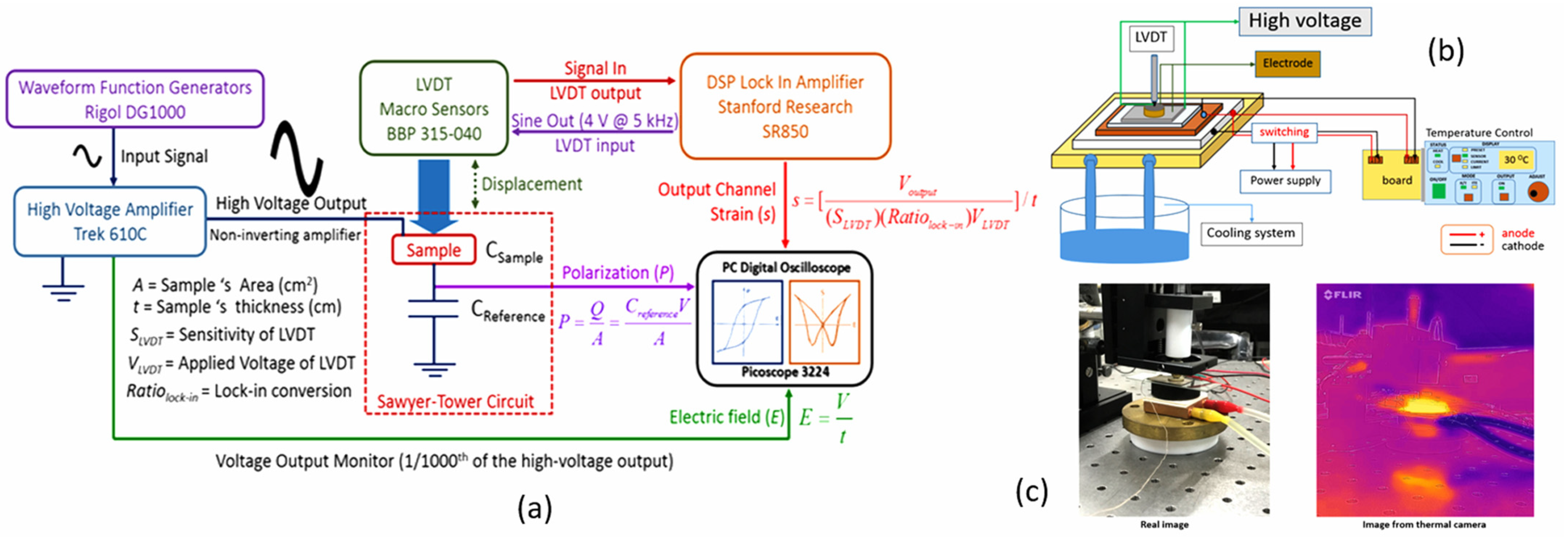
3.1. Strain Measurement Techniques

The discovery of piezoelectric effect by Pierre Curie and Jacques Curie shows an electric charge generated from stress in quartz. Converse piezoelectric effect is of interest in this review, where the electric field is applied to create strain in ceramic materials with 20 point groups of non-centro symmetry (i.e., actuating effect) [101]. Induced strain is related to both the converse piezoelectric (linear) and the electrostrictive effect (quadratic) [102,103]; however, only the linear term will be in focus (the so-called piezoelectric actuators) for PLZT-based ceramics, and the electrostrictive effect in ferroelectrics can be found in detail in the review by Li et al. [104]. The applications in micromechatronics require piezoelectric actuators with high performance combined with microprocessors and sensors to operate in high precision conditions in the range from μm to mm [105] and at the frequency up to 100 Hz [106].
Measurement of strain from a ratio of length change to original length gives rise to challenging problems in bulk ceramics. It should be noted that very small displacement results from an applied electric field and suitable strain measurement techniques should be used. There are several methods employed to measure strain from the converse piezoelectric effect. The simplest mode of measurement is quasistatic where the electric field induces displacement in ceramic samples [107]. In capacitive mode, the dimensional change of thickness and electrode area (geometric effect) causes the change of capacitance measured after the application of the electric field [108]. The limitation is pre-stress loading from clamping effect which results in lower accuracy, especially in relaxor ferroelectric PbTiO3 (PT) [107]. In lasers and optics, interferometry offers an opportunity to obtain accurate values of strain induced by an electric field. The measurement of light intensity as a result of interference can be used to determine strain from the path difference. The single beam Michelson interferometer, double beam Mach-Zehnder interferometer, and laser scanning vibrometer are optical techniques used for different situations [13]. Michelson interferometry is one of the most common methods where reasonable resolution can be obtained with the only limitation being noise from instruments and environment. Mach-Zehnder interferometry is applied to overcome the substrate bending but the setup is more complicated. However, suitable mounting technique in sample preparation for Michelson interferometry is sufficient to remedy the bending effect. A laser scanning vibrometer is used when the system has the vibration in micrometer scale (from electrical or mechanical effect) and a Doppler shift frequency from the measurement is used to obtain sample displacement [2]. The main strain measurement technique discussed in this review will be Michelson interferometry.

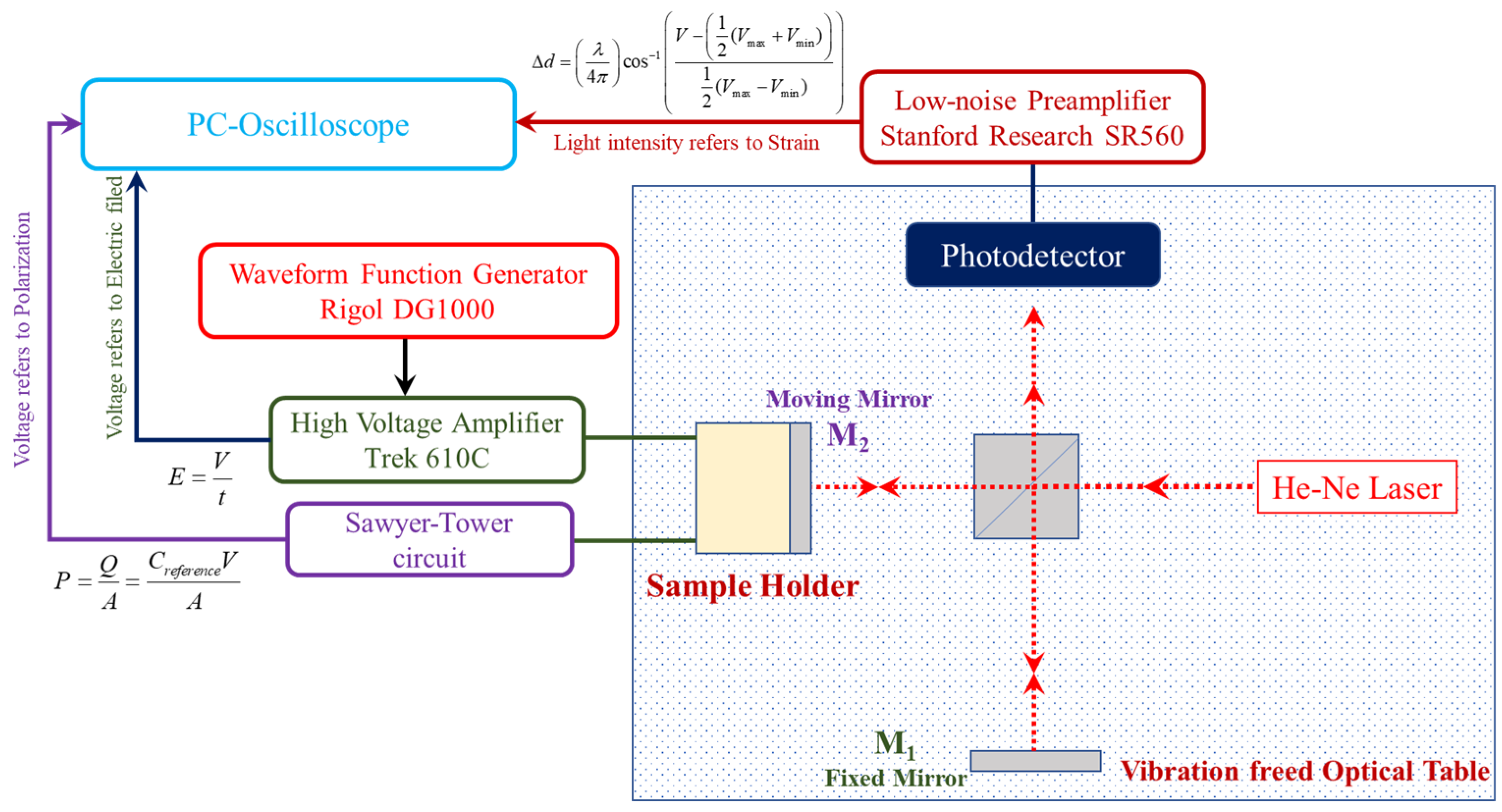
3.1.1. Michelson Interferometer

Michelson interferometer is a single beam technique used for strain measurement [13]. In setup (Figure 3), a polarized beam from a monochromatic source (usually Helium-Neon laser at 632.8 nm) travels past the beam splitter and two beams (measuring and reference beams) reflect at the mirrors M1 (fixed mirror) and M2 (moving mirror). Then, the reflected beams travel back to interfere with each other, resulting in a circular fringe pattern on the screen connected to the photodiode. The output of photodiode (electrical signal as voltage) can be calculated from interference light intensity where a reverse bias circuit is used to detect a light signal. The electrical signal is subjected to lower pass filtered process to eliminate electrical noise at the frequency higher than 30 Hz and amplify the signal to 2-gain of the signal amplitude by the low-noise preamplifier. The amplified interference signal (strain) is detected by PC-oscilloscope at the same time as the signal from Sawyer-Tower circuit (electrical polarization) and the high voltage (1/1000 reduced ratio signal) applied to the sample. The high voltage signal, which can be converted to an electrical field, is generated from a 15 MHz signal generator connected to the computer and a signal control system. The overall setup is fixed on the vibration freed optical table to eliminate the vibration noise.

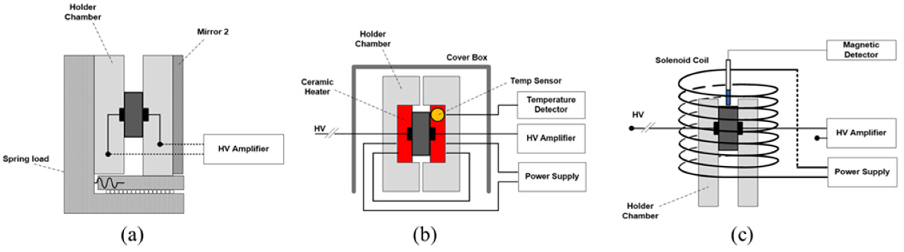
3.1.2. Sample Holders

A sample holder is an important measurement apparatus. Careful setting prior to the experiment is required to prevent the effect of sample geometry and static pre-loading [109]. From the schematic diagram of the setup in Figure 3, it can be seen that the sample holder is attached with the surface-coated mirror (M2). The design of sample holders in this review is shown in Figure 4. There are three types of sample holders according to strain measurement, namely standard (for electric field and frequency dependence), temperature dependent, and with applied magnetic field measurement (to study the effect of the magnetic field).
The standard sample holder is designed to fit samples and to maintain a good contact by a spring load to keep the holder surface in contact with (close to) the sample surface. The friction caused by the displacement resulting from the electric field is remedied by placing the moving side of the sample holder on two parallel bearings. The high strength voltage amplifier is connected to the two sides of the sample surface by passing through the sample holder in the middle, where one side of the sample holder is glued with the surface-coated mirror (M2) to reflect the laser beam from displaced samples, as shown in Figure 4a.
In order to investigate the temperature dependence of the sample in relation to the phase transition, the heat-loaded sample holder is required. The operation is in the range from room temperature up to 150 °C and the temperature of the sample can be controlled and displayed with high accuracy (±0.5 °C), as shown in Figure 4b. The ceramic heater is selected for this propose and it is inserted inside the sample holder at the center where ceramic heater surface is attached to the sample surface to evenly distribute the heat to two sides of the sample surface. The temperature of the sample is a function of the electrical current (passed through a ceramic heater) applied from the programmable DC power supply, and the temperature is detected by the integral circuit temperature detector which is placed close to the sample to observe the real-time sample temperature.
To investigate the effect of the magnetic field to the induced strain behavior of the materials, the solenoid coil is designed to apply the magnetic field to the sample inside the sample holder, as shown in Figure 4c. The magnetic field can be controlled as a function of the electrical current from the programmable DC power supply, and is detected by the Gauss meter which measures magnetic field along the center position of the solenoid coil where the sample is placed to observe the actual real magnetic field at the position of sample.

3.2. Case Studies in PLZT-Based Ceramics
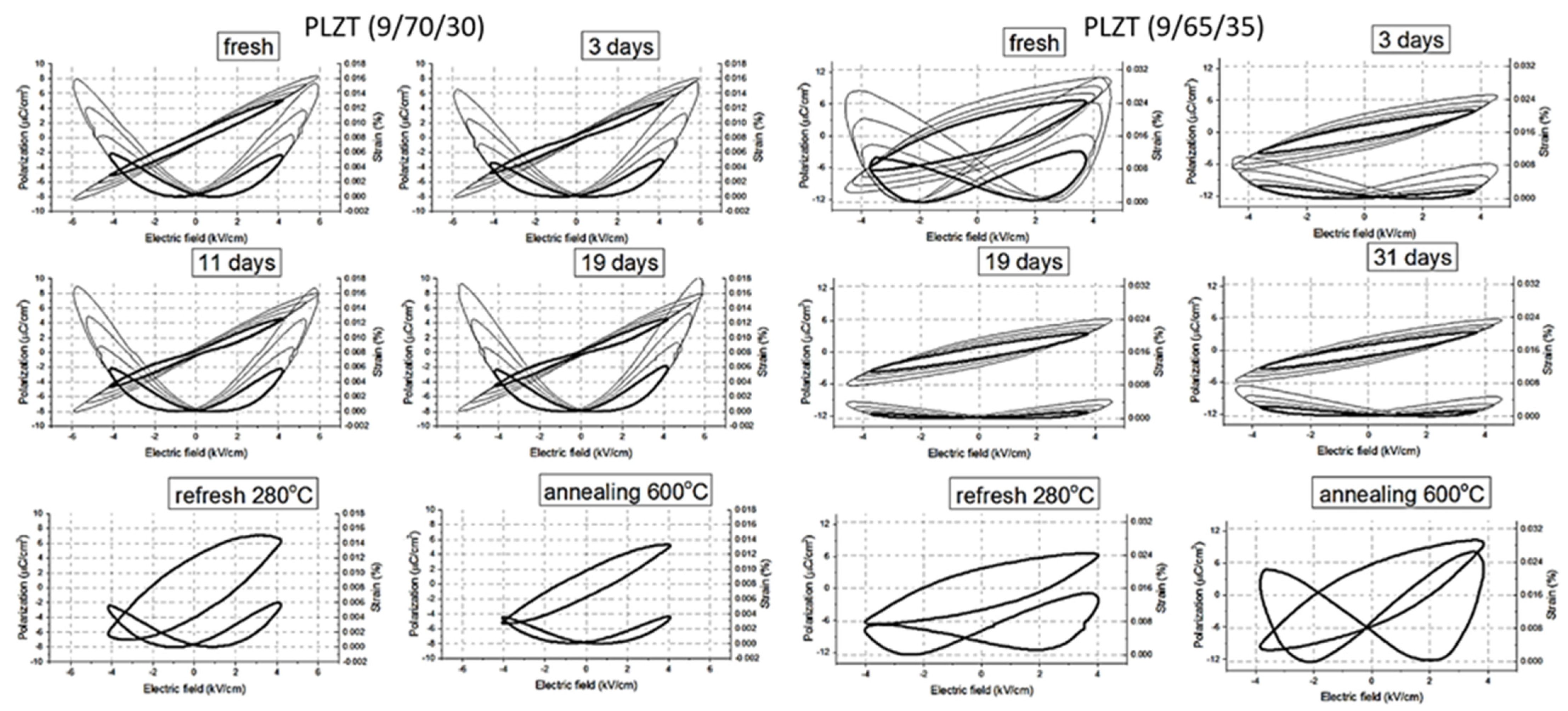
3.2.1. Aging Effect

Time-dependent change of dielectric, ferroelectric and piezoelectric properties can be observed in ceramic materials. The aging effect can be categorized into two types: irreversible and reversible aging. The irreversible effect involves the evolution of microcracks in ceramic materials caused by loading cycles. The control of phase fraction is an important key to improve fatigue resistance. The rhombohedral phase is responsible for both 180° and non-180° domain switching whereas the tetragonal phase contributes to only 180° domain switching and 90° domain switching is suppressed. Therefore, a higher fraction of tetragonal phase would give rise to a higher fatigue resistance [110]. Reversible effect is the main point of discussion in this review and the effect is caused by defects and oxygen vacancies. After sintering, ferroic samples are cooled down and phase transition can occur, which causes the change of the energy inside and also the stability. The model of energy profile for the domain walls is explained in detail by Damjanovic [111]. Possible phenomena during aging at room temperature include the reorientation of charged defects and oxygen vacancies (defect dipoles) parallel to the spontaneous polarization, diffusion of mobile defects at domain walls, and space-charge accumulation at grain boundaries [112]. As a result, a decrease in dielectric constant, a reduction in domain wall mobility, and pinched (unpoled) as well as asymmetric (poled) hysteresis loops can be seen as indication of aging effect [113]. The reverse effect of aging is called de-aging or rejuvenation where ferroic samples are subjected to applied bipolar cycles at appropriate amplitude, light illumination or heating above Curie temperature and then quenching to room temperature [112].
Aging in acceptor-doped ceramics (BT- and PZT-based) with large induced strain is reported [18]. Genenko et al. [114] suggested that aging mechanisms in PZT-based ceramics depend on type and concentration of dopants, which are responsible for the mobility of oxygen vacancies (short and long range) and defect dipole reorientation (short range). Dielectric aging of Cr-doped PZT ceramics was investigated by Ketsuwan et al. [115]. It was found that the aging rate followed a logarithmic time dependence at the stable stage and an increasing amount of Cr2O3 increased the aging rate. Burkhanov et al. [116] proposed an aging mechanism of PLZT with a Zr/Ti ratio of 65/35. When the content of La was 9 mol% (MPB region), aging behavior can be seen at the temperature higher and lower than Tm. The interaction between polar nanoregions (PNRs) and point defects played an important role to dielectric properties, and the decrease in dielectric constant resulted from the diffusion of point defects to the phase boundaries of PNRs over time (even at low temperature).
Somwan and Ngamjarurojana [117] studied aging behavior of PLZT 9/70/30 and 9/65/35 ceramics (composition close to MPB). Figure 5 shows the aging effect in terms of polarization and induced strain. At zero electric field, both fresh samples had remnant polarization and induced strain but they decreased as a function of time when the samples were left to age for 3, 11 and 19 days. Characteristic pinched loop could be seen in PLZT 9/70/30 and remnant polarization of PLZT 9/65/35 was close to zero after 19 days of aging. Interestingly, maximum induced strain was slightly decreased in PLZT 9/70/30 but significantly decreased in PLZT 9/65/35 and characteristic asymmetric butterfly loop was observed in PLZT 9/65/35 after 31 days of aging. The possible explanation of aging was the rearrangement of defect dipoles in crystal structure to reduce spontaneous polarization [114,118] and the clamping of domain walls by defects (from either migration or interaction with an oxygen vacancy-acceptor dipole pair) [119]. Moreover, compositional effect (different Zr/Ti ratio and therefore a different amount of rhombohedral and tetragonal in the mixture of crystal structure) also gave rise to different aging behavior and denser microstructure resulted in less pronounced aging effect [117].
When the samples were refreshed (heated to 280 °C, which was significantly higher than Tm, and quenched), de-aging occurred as remnant polarization and strain increased in both samples. Flattening of a free energy profile after thermal activation during de-aging led to preferred polarization rotation in PLZT 9/70/30 (rhombohedral) and a flatter energy profile in PLZT 9/65/35 (MPB) suggested polarization along different directions (more pronounced polarization rotation) [120]. The enhancement of asymmetric induced strain was also observed resulting from the anisotropy in piezoelectric properties close to MPB composition [121]. However, the co-existence of a monoclinic phase caused by an electric field-induced phase transformation [21] might be worth investigating to explain the effect of aging in the future.
When the samples were annealed (heated to 280 °C, quenched, heated to 600 °C, and then quenched again), remnant polarization and induced strain decreased in PLZT 9/70/30 but increased in PLZT 9/65/35 (compared to the refreshed samples). At higher temperatures, defects and oxygen vacancies could be trapped at domain walls and the mobility of domain walls changed [116], where rhombohedral PLZT 9/70/30 experienced the restriction of 180° domains and PLZT 9/65/35 close to MPB benefited the enhancement of electrostrictive properties from distortion of the tetragonal phase by non-180° domains and therefore the improved properties after annealing.

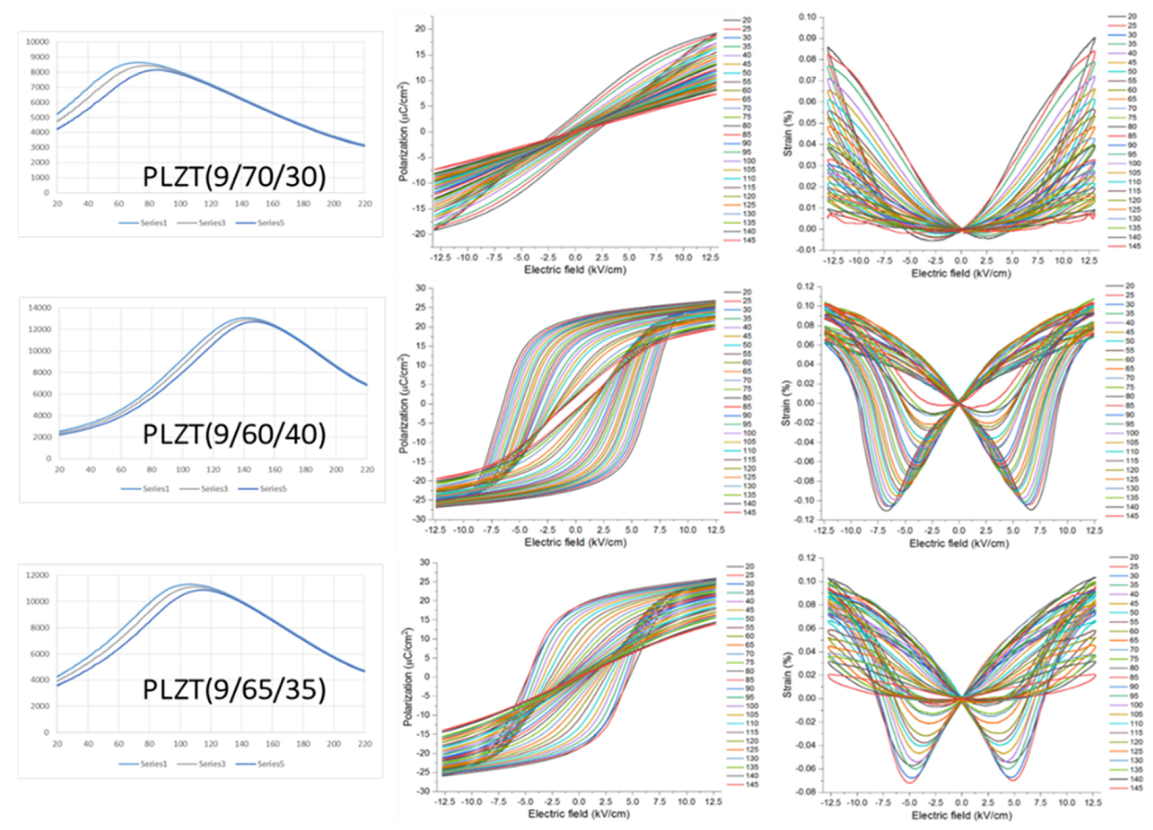
3.2.2. Temperature Dependence

The strain and polarization measurement system consists of a linear variable differential transformer (LVDT), DSP lock-in amplifier, high voltage power supply and computerized control and data acquisition (Figure 6a). The high voltage amplifier generates sine wave to sample by a waveform function generator. The hysteresis loop can be obtained by Sawyer-Tower and butterfly loops can be obtained by detection of voltage output by a DSP lock-in amplifier. Data acquisition is performed by PC digital oscilloscope. The data plot shows the relation of butterfly and hysteresis loop with the electric field. The operation to investigate the temperature dependence of ferroelectric materials is in the range from room temperature to 140 °C and the temperature of the sample can be controlled and displayed by thermoelectric temperature controller.
The schematic diagram of modification of strain and the polarization measuring system with temperature control is shown in Figure 6b. The cooling system consists of copper stage link with pipe and pump. The water liquid flow reduces the temperature of the thermoelectric component (TEC), which is employed to control heating and cooling. A thermoelectric is a solid-state active heat pump which transfers heat from one side of the device to the other, with consumption of electrical energy (DC power) depending on the electric current. The temperature controller generates current to TEC to increase temperature in a hot zone and it is in direct contact with the measurement part. The measurement stage consists of bulk copper with a pinning temperature sensor (±0.1 °C), insulator stage (glass slide) and silver plate for electrode contact. Figure 6c shows an image from an infrared camera detector (FLIR). This process is another method to confirm the actual temperature of the sample during measurement.
Temperature dependence of PZT-based ceramics, especially close to MPB composition, has been investigated [23,27,123,124,125]. Kungl and Hoffmann [123] systematically studied the effect of temperature to La- and Sr-doped PZT with Zr/Ti ratio in the MPB region. The results revealed that phase transition and additional strain from non-180° domains were responsible for the temperature dependence at high electric fields. Remnant strain occurred due to non-180° domain switching, and increasing domain wall mobility from lattice distortion. Compositional effect was also taken into account where MPB exhibited strong piezoelectric effect and domain switching. Rauls et al. [124] explained temperature dependence of PLZT 8/65/35 in terms of non-linear properties at high electric fields. The increase in temperature from 25 °C to 100 °C resulted in the change of induced strain curve from butterfly loop to quadratic and hysteresis loop of polarization to linear with a decrease in slope. Electrostrictive properties did not significantly depend on temperature, especially at the temperature below Tm. Ferroelectric and piezoelectric properties were altered by the formation of PNRs and nucleation to microdomains as temperature decreased and it was suggested that the crystal structure change from phase transition could also be included for further study.
Figure 7 shows temperature dependence of PLZT 9/70/30 (rhombohedral), 9/60/40 (tetragonal) and 9/65/35 (MPB) ceramics in terms of dielectric constant, polarization and induced strain. All samples showed relaxor behavior with broad dielectric peaks and Tm decreased as the Zr/Ti ratio increased with a shift to higher temperature when the frequency increased. Phase transition temperature of all samples could also be determined by the change of slope (second derivative) of the dielectric graph as reported by Somwan et al. [23]. When the temperature was increased, hysteresis loops were slimmer with a decrease in slope and remnant polarization as well as a decrease in the coercive field [124]. Maximum strain in butterfly loops was decreased as the temperature increased [126].
In case of PLZT 9/70/30, the defects from the B-site played an important role to induced strain behavior. At low temperatures, mixed domains of 180° and non-180° gave rise to high remnant polarization and induced strain at a high electric field [27]. When the temperature was increased, only non-180° domains were preferred. As a result, hysteresis loops became completely linear and butterfly loops became completely quadratic as PLZT 9/70/30 underwent phase transition to paraelectric. However, it should be noted that the pinched hysteresis loop and the change of induced strain behavior at low temperatures could not be observed at a low electric field [23]. For PLZT 9/60/40 ceramics, characteristic of square hysteresis loops in tetragonal phase could be seen at low temperatures, which became thinner when the temperature was increased. Butterfly loops had a lower magnitude of negative-induced strain at higher temperatures, indicating the transition from relaxor to ferroelectric state [27]. The mixed features resulting from MPB (mixed phases of rhombohedral and tetragonal) were observed in PLZT 9/65/35. As the temperature was increased, the mechanism changed from long-range ferroelectric to short-range relaxor (the formation of PNRs) [127]. Moreover, induced phase transition from the electric field and depolarization at higher temperatures from defect mobility towards domain walls were also possible [27]. Phase transition, polar ordering and crystal distortion in PLZT relaxor could be affected by the electric field, resulting in the change of domain size, density and mobility [52,128].

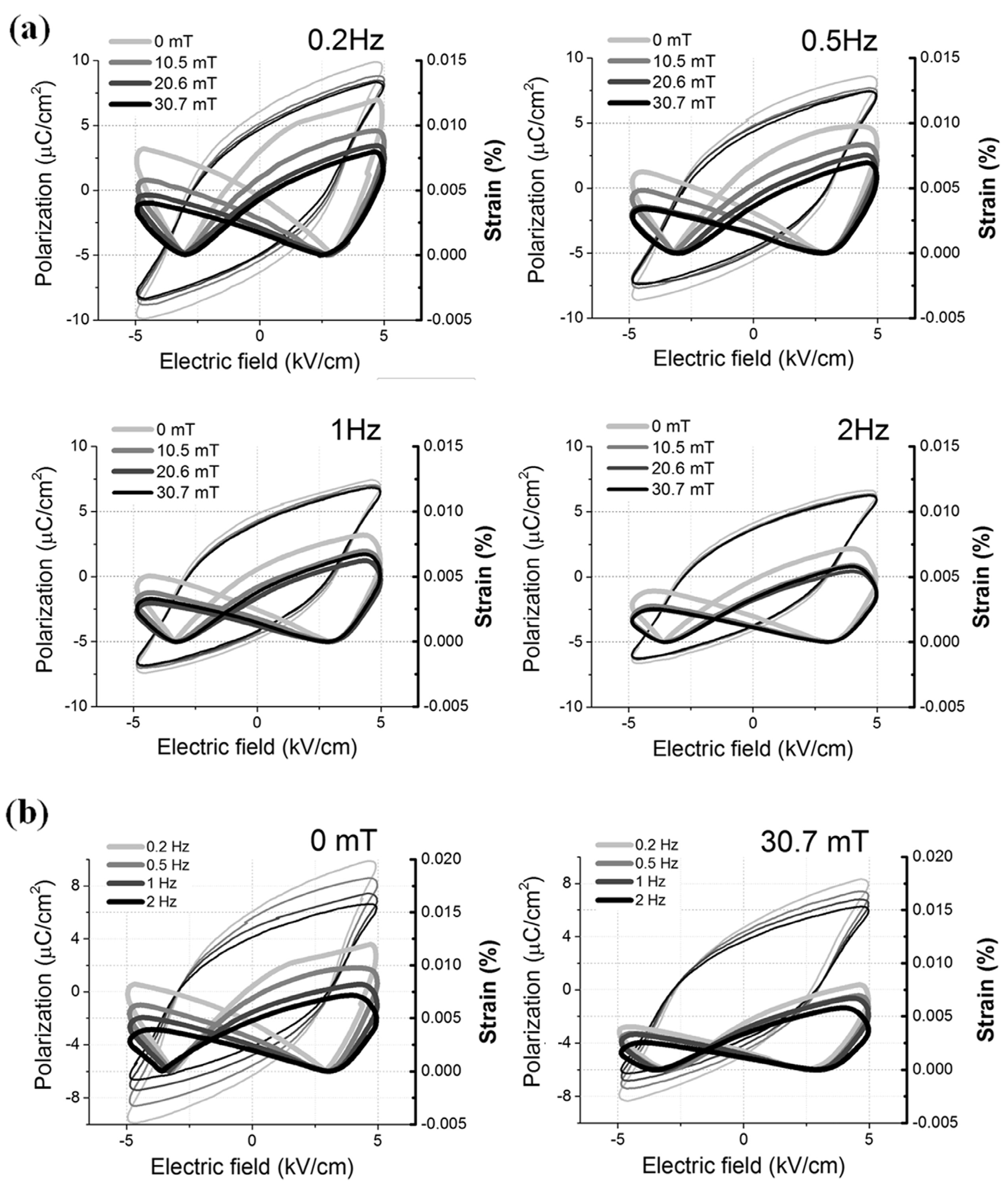
3.2.3. External Magnetic Field Effect

There have been very few studies on the effect of magnetic field-induced ferroelectric properties (the so-called magnetoelectric coupling), especially in bulk PLZT ceramics since multiferroic thin films in the form of layered structure between ferromagnetic and ferroelectric PLZT are more promising to induce magnetoelectric effect. Hu et al. [129] developed NiFe/PLZT heterostructures by magnetron sputtering with the thickness up to 3.2 nm. At room temperature, the applied voltage of 10 V and the magnetic field resonance field switching of 1.6 mT could be obtained. Magnetic anisotropy was created by interfacial charge effect or polarization of the ferroelectric layer. Kumar et al. [130] fabricated Ni-Mn-In/PLZT heterostructure with ferromagnetic property and the bilayer film exhibited magnetostriction and magnetoelectric coupling. The promising application could be mid-IR photothermal modulation where the presence of the magnetic field changed the response due to an increase in polarization and the spin-polarized free charge carriers. Other applications for magnetoelectric coupling materials include drug delivery, brain imaging, brain stimulation, cell regeneration and electrocatalysts [131] but they are very limited in PLZT-based ceramics due to lead-based component.
Figure 8 shows the results of the external magnetic field effect in PLZT 9/65/35 bulk ceramic by Somwan et al. [132]. The influence of the magnetic field caused a slight decrease in polarization but a noticeable decrease in induced strain (Figure 8a) and frequency dependence was less pronounced under the application of a static magnetic field (30.7 mT). The most plausible explanation of the decrease in polarization and induced strain was the suppression of some 180° domain [124] from the magnetic field. Moreover, the magnetic field could possibly induce depolarization from interfacial charge and also change the stored energy from electric dipole displacement [132].

4. Concluding Remarks

This review presents the perspectives of characteristic strain in PLZT-based ceramics for actuator applications, starting from crystal structures and properties of PLZT, defect chemistry at the grain boundaries and pore structure, improvement of properties by means of doping and compositing, and finally strain measurement to study aging effect, temperature dependence, and external magnetic field effect. There are a few points that need to be summarized:
  • Bulk properties are generally investigated in ceramic samples. However, grain boundaries should be taken into account to better understand dielectric, ferroelectric, and piezoelectric properties. Migration of defects towards grain boundaries causes the change of electrical properties, and segregation at grain boundaries results in the change of grain boundary composition.
  • Production of PLZT ceramics using sintering aids to create a glassy phase is still ongoing. The main advantage is a significant decrease in sintering temperature and a dense microstructure with a glassy phase at the grain boundaries. In terms of composites, multiferroic ceramics can be developed by a suitable selection of matrix and reinforcement. Doping is, in addition, still quite promising to enhance dielectric, ferroelectric, and piezoelectric properties as one of the most common methods. Co-doping offers the possibility to obtain a significant improvement of electrical properties in PLZT-based ceramics.
  • Michelson interferometry is a useful method for strain measurement because a small change of sample length can be detected. Sample holders can be equipped with additional instruments to measure strain in different conditions. Further study of aging and temperature dependence is required to develop actuators that can function in the extreme conditions of high cycle services or high temperatures. The effect of an external magnetic field can be further investigated to apply the knowledge for devices utilizing magnetoelectric properties.

Author Contributions

Conceptualization, A.L. and A.N.; writing—original draft preparation, A.L. and A.N.; writing—review and editing, A.L. and A.N.; visualization, A.L. and A.N. All authors have read and agreed to the published version of the manuscript.

Funding

This research received no external funding.

Data Availability Statement

The authors confirm that the data including in this review are available within the article and may be available from the corresponding author (A.N.) upon request.

Acknowledgments

The authors would like to thank Faculty of Science, Chiang Mai University, for facility support. A.L. would like to dedicate this manuscript to his beloved paternal grandmother [T. Limpichaipanit (陳嬋銀): 1926–2022] who always gave him unconditional love and unwavering support. A.N. is thankful to Kenji Uchino for conception, knowledge and experience from International Center for Actuators and Transducers (ICAT), Pennsylvania State University.

Conflicts of Interest

The authors declare no conflict of interest. The funders had no role in the design of the study; in the collection, analyses, or interpretation of data; in the writing of the manuscript; or in the decision to publish the results.

References

  1. Moulson, A.J.; Herbert, J.M. Electroceramics: Materials, Properties, Applications, 2nd ed.; John Wiley & Sons: Chichester, UK, 2003; pp. 433–468. [Google Scholar]
  2. Sabat, R.G. Characterization of PLZT Ceramics for Optical Sensor and Actuator Devices. In Ceramic Materials—Progress in Modern Ceramics; Shi, F., Ed.; InTech Open: London, UK, 2012; pp. 1–24. [Google Scholar] [CrossRef]
  3. Knopf, G.K.; Uchino, K. Light Driven Micromechanics, 1st ed.; CRC Press: Boca Raton, FL, USA, 2018; pp. 171–196. [Google Scholar] [CrossRef]
  4. Poosanaas, P.; Uchino, K. Photostrictive effect in lanthanum-modified lead zirconate titanate ceramics near the morphotropic phase boundary. Mater. Chem. Phys. 1999, 61, 36–41. [Google Scholar] [CrossRef]
  5. Poosanaas-Burke, P.; Abothu, I.R.; Uchino, K. Fabrication and Device Design of Bulk and Thin Films Photostrictive Materials. In Proceedings of the IEEE Instrumentation and Measurement Technology Conference, Budapest, Hungary, 21–23 May 2001. [Google Scholar]
  6. Chen, C.; Li, X.; Lu, T.; Liu, Y.; Yi, Z. Reinvestigation of the photostrictive effect in lanthanum-modified lead zirconate titanate ferroelectrics. J. Am. Ceram. Soc. 2020, 103, 4074–4082. [Google Scholar] [CrossRef]
  7. Li, B.; Liu, Q.; Tang, X.; Zhang, T.; Jiang, Y.; Li, W.; Luo, J. High energy storage density and impedance response of PLZT 2/95/5 antiferroelectric ceramics. Materials 2017, 10, 143. [Google Scholar] [CrossRef] [PubMed]
  8. Liu, Y.; Wang, X.; Wang, J.; Chen, H. The light-controlled actuator driven by the novel opto-electronic hybrid driving method based on PLZT ceramics. Int. J. Appl. Electromagn. Mech. 2020, 62, 283–294. [Google Scholar] [CrossRef]
  9. Lv, Z.; Uzair, M.; Wang, X.; Liu, Y. A closed-loop control mathematical model for photovoltaic-electrostatic hybrid actuator with a slant lower electrode based on PLZT ceramics. Actuators 2021, 10, 285. [Google Scholar] [CrossRef]
  10. Huang, J.; Jiang, C.; Li, G.; Lu, Q.; Chen, H. Design and analysis of a light-operated microgripper using an opto-electrostatic repulsive combined actuator. Micromechanics 2021, 12, 1026. [Google Scholar] [CrossRef]
  11. Haertling, G.H. Ferroelectric ceramics: History and technology. J. Am. Ceram. Soc. 1999, 82, 797–818. [Google Scholar] [CrossRef]
  12. Feng, Y.; Wu, J.; Chi, Q.; Li, W.; Yu, Y.; Fei, W. Defects and aliovalent doping engineering in electroceramics. Chem. Rev. 2020, 120, 1710–1787. [Google Scholar] [CrossRef]
  13. Huang, Z.; Leighton, G. Interferometry for Piezoelectric Materials and Thin Films. In Characterization of Ferroelectric Bulk Materials and Thin Films, Springer Series in Measurement Science and Technology 2; Cain, M.G., Ed.; Springer Verlag: New York, NY, USA, 2014; pp. 87–113. [Google Scholar] [CrossRef]
  14. Rödel, J.; Li, J.-F. Lead-free piezoceramics: Status and perspectives. MRS Bull. 2018, 43, 576–580. [Google Scholar] [CrossRef]
  15. Acosta, M. Theoretical Background. In Strain Mechanisms in Lead-Free Ferroelectrics for Actuators; Springer International Publishing: Cham, Switzerland, 2016; pp. 27–37. [Google Scholar] [CrossRef]
  16. Baker, A.; Gou, H.; Guo, J.; Randall, C. Utilizing the cold sintering process for flexible-printable electroceramic device fabrication. J. Am. Ceram. Soc. 2016, 99, 3202–3204. [Google Scholar] [CrossRef]
  17. Chumprasert, L.; Limpichaipanit, A.; Chokethawai, K.; Ananta, S.; Ngamjarurojana, A. Effect of soaking time on phase formation and electrical properties of PLZT based ceramics. Ferroelectrics 2013, 457, 16–22. [Google Scholar] [CrossRef]
  18. Hao, J.; Li, W.; Zhai, J.; Chen, H. Progress in high-strain perovskite piezoelectric ceramics. Mater. Sci. Eng. R 2019, 135, 1–57. [Google Scholar] [CrossRef]
  19. Ramam, K.; Miguel, V. Microstructure, dielectric and ferroelectric characterization of Ba doped PLZT ceramics. Eur. Phys. J. Appl. Phys. 2006, 35, 43–47. [Google Scholar] [CrossRef]
  20. Hinterstein, M.; Rouquette, J.; Haines, J.; Papet, P.; Knapp, M.; Glaum, J.; Fuess, H. Structural description of the macroscopic piezo- and ferroelectric properties of lead zirconate titanate. Phys. Rev. Lett. 2011, 107, 077602. [Google Scholar] [CrossRef]
  21. Kumar, A.; Kalyani, A.K.; Ranjan, R.; Raju, K.C.J.; Ryu, J.; Park, N.; James, A.R. Evidence of monoclinic phase and its variation with a temperature at morphotropic phase boundary of PLZT ceramics. J. Alloys Compd. 2020, 816, 152613. [Google Scholar] [CrossRef]
  22. Hinterstein, M.; Hoelzel, M.; Rouquette, J.; Haines, J.; Glaum, J.; Kungl, H.; Hoffman, M. Interplay of strain mechanisms in morphotropic piezoceramics. Acta Mater. 2015, 94, 319–327. [Google Scholar] [CrossRef]
  23. Somwan, S.; Funsueb, N.; Limpichaipanit, A.; Ngamjarurojana, A. Temperature and induced electric field dependence on the phase transition of 9/70/30, 9/65/35 and 9/60/40 PLZT ceramics. Phase Transit. 2018, 91, 461–468. [Google Scholar] [CrossRef]
  24. Tilley, R.J.D. Perovskites: Structure-Property Relationships, 1st ed.; John Wiley & Sons: Chichester, UK, 2016; pp. 208–212. [Google Scholar]
  25. Samara, G.A. The relaxational properties of compositionally disordered ABO3 perovskites. J. Phys. Condens. Matter 2003, 15, R367–R411. [Google Scholar] [CrossRef]
  26. James, A.R.; Kumar, A. Development of PLZT Electroceramics with Ultrahigh Piezoelectric Properties by A Novel Material Engineering Approach. In Handbook of Advanced Ceramics and Composites; Mahajan, Y., Johnson, R., Eds.; Springer Nature Switzerland AG: Cham, Switzerland, 2020; pp. 1–36. [Google Scholar] [CrossRef]
  27. Funsueb, N.; Limpichaipanit, A.; Ngamjarurojana, A. Temperature dependence on ferroelectric properties and strain performance of PLZT ceramics containing 9 mol% La. Phase Transit. 2020, 93, 678–689. [Google Scholar] [CrossRef]
  28. Maier, J. Transport in electroceramics: Micro- and nano- structural aspects. J. Eur. Ceram. Soc. 2004, 24, 1251–1257. [Google Scholar] [CrossRef]
  29. Waser, R.; Hagenbeck, R. Grain boundaries in dielectric and mixed-conducting ceramics. Acta Mater. 2000, 48, 797–825. [Google Scholar] [CrossRef]
  30. Cantwell, P.R.; Tang, M.; Dillon, S.J.; Luo, J.; Rohrer, G.S.; Harmer, M.P. Grain boundary complexions. Acta Mater. 2014, 62, 1–48. [Google Scholar] [CrossRef]
  31. Bowman, W.J.; Kelly, M.N.; Rohrer, G.S.; Hernandez, C.A.; Crozier, P.A. Enhanced ionic conductivity in electroceramics by nanoscale enrichment on grain boundaries with high solute concentration. Nanoscale 2017, 9, 17293–17302. [Google Scholar] [CrossRef] [PubMed]
  32. Okazaki, K.; Nagata, K. Effects of grain size and porosity on electrical and optical properties of PLZT ceramics. J. Am. Ceram. Soc. 1973, 56, 82–86. [Google Scholar] [CrossRef]
  33. Jiang, Q.Y.; Cross, L.E. Effects of porosity on electrical fatigue behavior in PLZT and PZT ferroelectric ceramics. J. Mater. Sci. 1993, 28, 4536–4543. [Google Scholar] [CrossRef]
  34. Curecheriu, L.; Lukacs, V.A.; Padurariu, C.; Stoian, G.; Ciomaga, C.E. Effect of porosity on functional properties of lead-free piezoelectric BaZr0.15Ti0.85O3 Porous Ceramics. Materials 2020, 13, 3224. [Google Scholar] [CrossRef]
  35. Zhou, X.; Zhou, K.; Zhang, D.; Bowen, C.; Wang, Q.; Zhong, J.; Zhang, Y. Perspective on porous piezoelectric ceramics to control unternal stress. Nanoenerg. Adv. 2022, 2, 269–290. [Google Scholar] [CrossRef]
  36. Zhang, Y.; Roscow, J.; Lewis, R.; Khanbareh, H.; Topolov, V.Y.; Xie, M.; Bowen, C.R. Understanding the effect of porosity on the polarisation-field response of ferroelectric materials. Acta Mater. 2018, 154, 100–112. [Google Scholar] [CrossRef]
  37. Liang, R.; Zhang, W.; Gao, M.; Wang, L.; Dong, X. Excellent electrostrictive properties of low temperature sintered PZT ceramics with high concentration LiBiO2 sintering aid. Ceram. Int. 2013, 39, 563–569. [Google Scholar] [CrossRef]
  38. Liu, Z.; Shi, D.; Zhiu, H.; Deng, L.; Li, K. Fabrication and evaluation of Pb(W0.5Cu0.5)O3 modified PLZT piezoelectric ceramics. Ceram. Int. 2015, 41, 941–946. [Google Scholar] [CrossRef]
  39. Limpichaipanit, A.; Ngamjarurojana, A. Effect of PbO/CuO addition to microstructure and electrical properties of PLZT 9/65/35. Ferroelectrics 2015, 486, 57–65. [Google Scholar] [CrossRef]
  40. Yadav, A.K.; Gautam, C.R. A review on crystallization behaviour of perovskite glass ceramics. Adv. Appl. Ceram. 2014, 113, 193–207. [Google Scholar] [CrossRef]
  41. Hu, Q.; Wang, T.; Zhao, L.; Jin, L.; Xu, Z.; Wei, X. Dielectric and energy storage properties of BaTiO3-Bi(Mg1/2Ti1/2)O3 ceramic: Influence of glass addition and biasing electric field. Ceram. Int. 2017, 43, 35–39. [Google Scholar] [CrossRef]
  42. Khalf, A.Z.; Hall, D.A. Influence of barium borosilicate glass on microstructure and dielectric properties of (Ba,Ca)(Zr,Ti)O3 ceramics. J. Eur. Ceram. Soc. 2018, 38, 4422–4432. [Google Scholar] [CrossRef]
  43. Li, T.; Segawa, H.; Ohashi, N. Exploration of BaO-B2O3-Bi2O3 glasses as sintering aids for BaTiO3 ceramics. Ceram. Int. 2020, 46, 10233–10241. [Google Scholar] [CrossRef]
  44. Kanai, T.; Ohkoshi, S.; Nakajima, A.; Watanabe, T.; Hashimoto, K. A ferroelectric ferromagnet composed of (PLZT)x(BiFeO3)1−x solid solution. Adv. Mater. 2001, 13, 487–490. [Google Scholar] [CrossRef]
  45. Fawzi, A.S.; Sheikh, A.D.; Mathe, V.L. Multiferroic properties of Ni ferrite-PLZT composites. Phys. B 2010, 405, 340–344. [Google Scholar] [CrossRef]
  46. Fawzi, A.S.; Sheikh, A.D.; Mathe, V.L. Dielectric, electrical and magnetoelectric characterization of (x)Ni0.8Zn0.2Fe2O4 + (1 − x)Pb0.93La0.07(Zr0.60Ti0.40)O3 composites. Mater. Res. Bull. 2010, 45, 1000–1007. [Google Scholar] [CrossRef]
  47. Rani, R.; Juneya, J.K.; Singh, S.; Raina, K.K.; Prakash, C. Study of 0.1Ni0.8Zn0.2Fe2O4-0.9Pb1−3x/2LaxZr0.65Ti0.35O3 magnetoelectric composites. J. Mag. Mag. Mater. 2013, 325, 47–51. [Google Scholar] [CrossRef]
  48. Bochenek, D.; Miemiec, P.; Korzekwa, J.; Durtka, B.; Stokłosa, Z. Microstructure and properties of the ferroelectric-ferromagnetic PLZT-ferrite composites. Symmetry 2018, 10, 59. [Google Scholar] [CrossRef]
  49. Thommerel, E.; Madigou, V.; Villian, S.; Musso, J.; Valmalette, J.-C.; Gavarn, J.-R. Microstructure modifications and modulated piezoelectric responses in PLZT/Al2O3 composites. Mater. Sci. Eng. B 2003, 97, 74–82. [Google Scholar] [CrossRef]
  50. Qin, X.; Wu, H.; Chen, C.; Ao, H.; Li, W.; Gao, R.; Cai, W.; Chen, G.; Deng, X.; Wang, Z.; et al. Enhanced energy-storage performance of Pb0.925La0.05Zr0.95Ti0.05 @ x wt% SiO2 composite ceramics. J. Alloys Compd. 2021, 890, 161869. [Google Scholar] [CrossRef]
  51. Zhang, H.; Wei, T.; Zhang, Q.; Ma, W.; Fan, P.; Salamon, D.; Zhang, S.-T.; Nan, B.; Tau, H.; Ye, Z.-G. Review on the development of lead-free ferroelectric energy storage ceramics and multilayer capacitors. J. Mater. Chem. C 2020, 8, 16648–16667. [Google Scholar] [CrossRef]
  52. Funsueb, N.; Ngamjarurojana, A.; Tunkasiri, T.; Limpichaipanit, A. Effect of composition and grain size on dielectric, ferroelectric and induced strain behavior of PLZT/ZrO2 composites. Ceram. Int. 2018, 44, 6343–6353. [Google Scholar] [CrossRef]
  53. Zhang, N.X.; Li, L.T.; Li, B.R.; Guo, D.; Gui, Z.L. Improvement of electric fatigue properties in PLZT ferroelectric ceramics due to SrBi2Ta2O9 incorporation. Mater. Sci. Eng. B 2002, 90, 185–190. [Google Scholar] [CrossRef]
  54. Yin, Q.R.; Ding, A.L.; Zheng, X.S.; Qin, P.S. Preparation and characterization of transparent PZN-PLZT ceramics. J. Mater. Res. 2004, 19, 729–732. [Google Scholar] [CrossRef]
  55. Funsueb, N.; Limpichaipanit, A.; Ngamjarurojana, A. Effect of sintering temperature on phase formation and dielectric property of modified PLZT ceramics with addition of BT and PZN. Phase Transit. 2022, 95, 363–371. [Google Scholar] [CrossRef]
  56. Curecheriu, L.-P.; Buscaglia, M.T.; Maglia, F.; Padurariu, C.; Ciobanu, G.; Anselmi-Tamburini, U.; Buscaglia, V.; Mitoseriu, L. Tailoring the functional properties of PLZT-BaTiO3 composite ceramics by core-shell approach. J. Appl. Phys. 2017, 121, 144101. [Google Scholar] [CrossRef]
  57. Tilley, R.J.D. Understanding Solids: The Science of Materials, 2nd ed.; John Wiley & Sons: Chichester, UK, 2013; pp. 19–24. [Google Scholar]
  58. Zhu, B.; Zeng, X.; Qiu, P.; Ling, L.; Sun, D.; Zhao, S.; He, X. Effects of Bi3+ doping on the optical and electric-induced light scattering performance of PLZT (8.0/69/31) transparent ceramics. Materials 2019, 12, 1437. [Google Scholar] [CrossRef]
  59. Choudary, R.N.P.; Mal, J. Phase transition in Bi-modified PLZT ferroelectrics. Mater. Lett. 2002, 54, 175–180. [Google Scholar] [CrossRef]
  60. Dutta, S.; Choudhary, R.N.P.; Sinha, K. Ferroelectric phase transition in Bi-doped PLZT ceramics. Mat. Sci. Eng. B 2003, 98, 74–80. [Google Scholar] [CrossRef]
  61. Rai, R.; Sharma, S. Structural and dielectric properties of (La,Bi) modified PZT ceramics. Solid State Commu. 2004, 129, 305–309. [Google Scholar] [CrossRef]
  62. Kundzina, L.; Kundzins, M.; Kundzins, K.; Plaude, A.; Livinsh, M.; Antonova, M.; Dimza, V. The effects of 3d admixtures on properties of relaxor PLZT 8/65/35 ceramics. Ferroelectrics 2012, 436, 38–48. [Google Scholar] [CrossRef]
  63. Ahamad Mohiddon, M.; Yadav, K.L. Effect of Fe doping on dielectric, ferroelectric and pyroelectric properties of PLZT (8/65/35). J. Phys. D Appl. Phys. 2007, 40, 7540–7547. [Google Scholar] [CrossRef]
  64. Rai, R.; Sharma, S.; Chouhary, R.N.P. Dielectric and piezoelectric studies of Fe doped PLZT ceramics. Mater. Lett. 2005, 59, 3921–3925. [Google Scholar] [CrossRef]
  65. Limpichaipanit, A.; Somwan, S.; Ngamjarurojana, A. Dielectric properties of PFN–PZT composites: From relaxor to ferroelectric behavior. Ceram. Int. 2018, 44, 14797–14802. [Google Scholar] [CrossRef]
  66. Dutta, S.; Choudhary, R.N.P.; Sinha, P.K. Impedance spectroscopy studies on Fe3+ ion modified PLZT ceramics. Ceram. Int. 2007, 33, 13–20. [Google Scholar] [CrossRef]
  67. Dimza, V.; Popov, A.I.; Lāce, L.; Kundzins, M.; Kundzins, K.; Antonava, M.; Livins, M. Effects of Mn doping on dielectric properties of ferroelectric relaxor PLZT ceramics. Curr. Appl. Phys. 2017, 17, 169–173. [Google Scholar] [CrossRef]
  68. Kumar, A.; Yoon, J.Y.; Thakre, A.; Peddigari, M.; Jeong, D.-Y.; Kong, Y.-M.; Ryu, J. Dielectric, ferroelectric, energy storage, and pyroelectric properties of Mn doped (Pb0.93La0.07)(Zr0.82Ti0.18)O3 anti-ferroelectric ceramics. J. Korean Ceram. Soc. 2019, 56, 412–420. [Google Scholar] [CrossRef]
  69. Perez-Delfin, E.; García, J.E.; Ochoa, D.A.; Pérez, R.; Guerrero, F.; Eiras, J.A. Effect of Mn-acceptor dopant on dielectric and piezoelectric responses of lead lanthanum zirconate titanate piezoceramics. J. Appl. Phys. 2011, 110, 034106. [Google Scholar] [CrossRef]
  70. Ahamad Mohiddon, M.; Yadav, K.L. Dielectric dispersion study of Mn-doped PLZT (8/65/35). Phys. Status Solidi A 2009, 206, 1606–1615. [Google Scholar] [CrossRef]
  71. Bajpai, K.K.; Sreenivas, K.; Gupta, A.K.; Shukla, A.K. Cr-doped lead lanthanum zirconate titanate (PLZT) ceramics for pyroelectric and energy harvesting device applications. Ceram. Int. 2019, 45, 14111–14120. [Google Scholar] [CrossRef]
  72. Shukla, A.K.; Argawal, V.K.; Das, I.M.L.; Singh, J.; Singh, D.P.; Sood, K.N. Structural, dielectric and electrochemical properties of Cr-doped PLZT close to the morphotropic phase boundary region. Phase Transit. 2006, 79, 875–887. [Google Scholar] [CrossRef]
  73. Selvamani, R.; Singh, G.; Tiwari, V.S.; Karnal, A.K. Dielectric and piezoelectric properties of Cr2O3-doped PLZT (7/65/35) hot pressed ceramics. Mater. Today Commun. 2018, 15, 100–104. [Google Scholar] [CrossRef]
  74. Dutta, S.; Choudhary, R.N.P.; Sinha, P.K. Structural, dielectric and piezoelectric properties of aluminium doped PLZT ceramics prepared by sol–gel route. J. Alloys Compd. 2007, 430, 344–349. [Google Scholar] [CrossRef]
  75. Dutta, S.; Choudhary, R.N.P.; Sinha, P.K. Effect of Ga+3-ion Substitution on structural, dielectric and electrical properties of PLZT ceramics. Ferroelectrics 2006, 330, 75–84. [Google Scholar] [CrossRef]
  76. Zeng, X.; He, X.; Cheng, W.; Qiu, P.; Xia, B. Effect of Dy substitution on ferroelectric, optical and electro-optic properties of transparent Pb0.90La0.10(Zr0.65Ti0.35)O3 ceramics. Ceram. Int. 2014, 40, 6197–6202. [Google Scholar] [CrossRef]
  77. Płońska, M.; Adamczyk, M. Dielectric properties of neodymium-modified PLZT ceramics. Phase Transit. 2015, 88, 786–798. [Google Scholar] [CrossRef]
  78. Maher, G.H. Effect of silver doping on the physical and electrical properties of PLZT ceramics. J. Am. Ceram. Soc. 1983, 66, 408–413. [Google Scholar] [CrossRef]
  79. Tong, S.; Ling, Z. Ferroelectric-to-relaxor crossover in Sb doped PLZT x/52/48 (2 ≤ x ≤ 16) piezoelectric ceramics. J. Asian Ceram. Soc. 2014, 2, 1–4. [Google Scholar] [CrossRef]
  80. Dutta, S.; Choudhary, R.N.P.; Sinha, P.K. Electrical properties of antimony doped PLZT ceramics prepared by mixed–oxide route. J. Alloys Compd. 2006, 426, 345–351. [Google Scholar] [CrossRef]
  81. Rai, R.; Sharma, S. Structural and dielectric properties of Sb-doped PLZT ceramics. Ceram. Int. 2004, 30, 1295–1299. [Google Scholar] [CrossRef]
  82. Chu, S.-Y.; Uchino, K. Photostrictive effect in PLZT-based ceramics and its applications. Ferroelectrics 1995, 174, 185–196. [Google Scholar] [CrossRef]
  83. Favaretto, R.; Garcia, D.; Eiras, J.A. Effects of WO3 on the microstructure and optical transmittance of PLZT ferroelectric ceramics. J. Eur. Ceram. Soc. 2007, 27, 4037–4040. [Google Scholar] [CrossRef]
  84. Xu, Z.; Zeng, X.; Cao, Z.; Ling, L.; Qiu, P.; He, X. The electrical and optical properties of Nb-doping PLZT (9/65/35) transparent ceramics. J. Electroceramics 2020, 44, 215–222. [Google Scholar] [CrossRef]
  85. Divya, A.S.; Kumar, V. A novel mechanism for relaxor–ferroelectric transition in PLZT (8/65/35). J. Am. Ceram. Soc. 2009, 92, 2029–2032. [Google Scholar] [CrossRef]
  86. Xu, Z.; Zeng, X.; Cao, Z.; Ling, L.; Qiu, P.; He, X. Effects of barium substitution on the optical and electrical properties of PLZT transparent electro-optical ceramics. Ceram. Int. 2019, 45, 17890–17897. [Google Scholar] [CrossRef]
  87. Chen, Y.; Sun, D.; Zhu, Y.; Zeng, X.; Ling, L.; Qiu, P.; He, X. The effect of Sn4+ doping on the electrostrictive property of PLZT (9/65/35) transparent ceramics. Ceram. Int. 2020, 46, 6738–6744. [Google Scholar] [CrossRef]
  88. Zhang, Q.; Dan, Y.; Chen, J.; Lu, Y.; Yang, T.; Yao, X.; He, Y. Effects of composition and temperature on energy storage properties of (Pb,La)(Zr,Sn,Ti)O3 antiferroelectric ceramics. Ceram. Int. 2017, 43, 11428–11432. [Google Scholar] [CrossRef]
  89. Xu, R.; Tian, J.; Zhu, Q.; Zhao, T.; Feng, Y.; Wei, X.; Xu, Z. Effects of La-induced phase transition on energy storage and discharge properties of PLZST ferroelectric/antiferroelectric ceramics. Ceram. Int. 2017, 43, 13918–13923. [Google Scholar] [CrossRef]
  90. Choi, J.-S.; Kim, D.-C.; Shin, H.-S.; Yeo, D.-H.; Lee, J.-H. Effects of the Sn4+ substitution and the sintering additives on the sintering behavior and electrical properties of PLZT. Appl. Sci. 2022, 12, 2591. [Google Scholar] [CrossRef]
  91. Xu, R.; Xu, Z.; Feng, Y.; He, H.; Tian, J.; Yu, K. Fatigue resistance of Pb0.90La0.04Ba0.04[(Zr0.6Sn0.4)0.85Ti0.15]O3 antiferroelectric ceramics under fast charge-discharge cycling. Ceram. Int. 2016, 42, 9094–9099. [Google Scholar] [CrossRef]
  92. Wang, X.; Yang, T.; Shen, J. Unique dielectric behavior of (Pb0.87Ba0.08Sr0.02La0.02)(Zr0.65Sn0.27Ti0.08)O3 antiferroelectric ceramics. Mater. Lett. 2016, 181, 220–222. [Google Scholar] [CrossRef]
  93. Fu, S.-L.; Cheng, S.-Y.; Wei, C.-C. Effects on doping pairs on the preparation and dielectricity of PLZT ceramics. Ferroelectrics 1986, 67, 93–102. [Google Scholar] [CrossRef]
  94. Limpichaipanit, A.; Ngamjarurojana, A. Effect of Li and Bi co-doping and sintering temperature on dielectric properties of PLZT 9/65/35 ceramics. Ceram. Int. 2017, 43, 4450–4455. [Google Scholar] [CrossRef]
  95. Somwan, S.; Ngamjarurojana, A.; Limpichaipanit, A. Dielectric, ferroelectric and induced strain behavior of modified PLZT 9/65/35 by Bi2O3 and CuO co-doping. Ceram. Int. 2016, 42, 10690–10696. [Google Scholar] [CrossRef]
  96. Rai, R.; Mishra, S.; Singh, N.K. Effect of Fe and Mn doping at B-site of PLZT ceramics on dielectric properties. J. Alloys Compd. 2009, 487, 494–498. [Google Scholar] [CrossRef]
  97. Samanta, S.; Sankaranarayanan, V.; Senthupathi, K. Effect of Nb and Fe co-doping on microstructure, dielectric response, ferroelectricity and energy storage density of PLZT. J. Mater. Sci. Mater. Electron. 2018, 29, 20383–20394. [Google Scholar] [CrossRef]
  98. Ramam, K.; Chandramondi, K. Dielectric and piezoelectric properties of combinatory effect of A-site isovalent and B-site acceptor doped PLZT ceramics. Ceram.—Silik. 2009, 53, 189–194. [Google Scholar]
  99. Lu, B.; Yao, Y.; Jian, X.; Tao, T.; Liang, B.; Zhang, Q.M.; Lu, S.-G. Enhancement of the electrocaloric effect pver a wide temperature range in PLZT ceramics by doping with Gd3+ and Sn4+ ions. J. Eur. Ceram. Soc. 2019, 39, 1093–1102. [Google Scholar] [CrossRef]
  100. Limpichaipanit, A.; Funsueb, N.; Somwan, S.; Ngamjarurojana, A.; Tunkasiri, T. Electrocaloric properties of Bi and Cu doped PLZT 9/65/35 ceramics at low electric field. Ceram. Int. 2020, 46, 5252–5261. [Google Scholar] [CrossRef]
  101. Li, J.F. Lead-Free Piezoelectric Materials, 1st ed.; Wiley-VCH GmbH: Weinheim, Germany, 2021; pp. 1–18. [Google Scholar]
  102. Uchino, K. Ferroelectric Devices, 2nd ed.; Marcel Dekker Inc.: New York, NY, USA, 2009; pp. 1–22. [Google Scholar]
  103. Uchino, K. Ferroelectric Devices & Piezoelectric Actuators, 1st ed.; DEStech Publications: Lancaster, PA, USA, 2017; pp. 1–41. [Google Scholar]
  104. Li, F.; Jin, L.; Xu, Z.; Zhang, S. Electrostrictive effect in ferroelectrics: An alternative approach to improve piezoelectricity. Appl. Phys. Rev. 2014, 1, 011103. [Google Scholar] [CrossRef]
  105. Uchino, K.; Giniewicz, R. Micromechatronics, 1st ed.; Marcel Dekker Inc.: New York, NY, USA, 2003; pp. 1–36. [Google Scholar]
  106. Fan, P.; Liu, K.; Ma, W.; Tan, H.; Zhang, Q.; Zhang, L.; Zhou, C.; Salamon, D.; Zhang, S.-T.; Zhang, Y.; et al. Progress and perspective of high strain NBT-based lead-free piezoceramics and multilayer actuators. J. Mater. 2021, 7, 508–544. [Google Scholar] [CrossRef]
  107. Trolier-McKinstry, S. Piezoelectric Characterization. In Polar Oxides: Properties, Characterization, and Imaging; Waser, R., Böttger, U., Tiedke, S., Eds.; Wiley-VCH Verlag GmbH & Co. KGaA: Weinheim, Germany, 2005; pp. 39–52. [Google Scholar]
  108. Nesser, H.; Lubineau, G. Strain sensing by electrical capacitive variation: From stretchable materials to electronic interfaces. Adv. Electron. Mater. 2021, 7, 2100190. [Google Scholar] [CrossRef]
  109. Stewart, M.; Cain, M.G. Direct Piezoelectric Measurement: The Berlincourt Method. In Characterization of Ferroelectric Bulk Materials and Thin Films, Springer Series in Measurement Science and Technology 2; Cain, M.G., Ed.; Springer Verlag: New York, NY, USA, 2014; pp. 37–64. [Google Scholar] [CrossRef]
  110. Reichmann, K.; Feteira, A.; Li, M. Bismuth sodium titanate based materials for piezoelectric actuators. Materials 2015, 8, 8467–8495. [Google Scholar] [CrossRef] [Green Version]
  111. Damjanovic, D. Hysteresis in Piezoelectric and Ferroelectric Materials. In The Science of Hysteresis; Mayergoyz, I., Bertotti, G., Eds.; Academic Press: Oxford, UK, 2006; Volume 3, pp. 337–465. [Google Scholar]
  112. Koval, V.; Viola, G.; Tan, Y. Biasing Effects in Ferroic Materials. In Ferroelectric Materials-Synthesis and Characterization; Peláiz-Barranco, A., Ed.; InTech Open: London, UK, 2015; pp. 205–245. [Google Scholar] [CrossRef]
  113. Genenko, Y.A. Space-charge mechanism of aging in ferroelectrics: An analytically solvable two-dimensional model. Phys. Rev. B 2008, 78, 214103. [Google Scholar] [CrossRef]
  114. Genenko, Y.A.; Glaum, J.; Hoffmann, M.J.; Albe, K. Mechanisms of aging and fatigue in ferroelectrics. Mater. Sci. Eng. B 2015, 192, 52–82. [Google Scholar] [CrossRef]
  115. Ketsuwan, P.; Prasatkhetragarn, A.; Ngamjarurojana, A.; Ananta, S.; Yimnirum, R. Dielectric aging of Cr-doped PZT ceramics. Ferroelectrics 2013, 149, 67–74. [Google Scholar] [CrossRef]
  116. Burkhanov, A.; Shilnikov, A.; Sternberg, A. Aging and after-effects in PLZT X/65/35 ferroelectric ceramics. Ferroelectrics 1989, 90, 39–43. [Google Scholar] [CrossRef]
  117. Somwan, S.; Ngamjarurojana, A. Study of aging behavior of 9/70/30 and 9/65/35 PLZT by optical interferometric technique. Ceram. Int. 2015, 41, 7536–7542. [Google Scholar] [CrossRef]
  118. Somwan, S. Development of Michelson Interferometer for Induced-Strain Measurement in Ferroic Materials. Ph.D. Thesis, Chiang Mai University, Chiang Mai, Thailand, 2015. [Google Scholar]
  119. Damjanovic, D. Ferroelectric, dielectric and piezoelectric properties of ferroelectric thin films and ceramics. Rep. Prog. Phys. 1998, 61, 1267–1324. [Google Scholar] [CrossRef]
  120. Damjanovic, D. A morphotropic phase boundary system based on polarization rotation and polarization extension. Appl. Phys. Lett. 2010, 97, 062906. [Google Scholar] [CrossRef]
  121. Damjanovic, D. Contributions to piezoelectric effect in ferroelectric single crystals and ceramics. J. Am. Ceram. Soc. 2005, 88, 2663–2676. [Google Scholar] [CrossRef]
  122. Funsueb, N. Investigation on Strain Characteristics of Ferroelectric Ceramics for Micromechatronic Actuator. Ph.D. Thesis, Chiang Mai University, Chiang Mai, Thailand, 2020. [Google Scholar]
  123. Kungl, H.; Hoffmann, M.J. Temperature dependence of poling strain and strain under high electric fields in LaSr-doped morphotropic PZT and its relation to changes in structural characteristics. Acta Mater. 2007, 55, 5780–5791. [Google Scholar] [CrossRef]
  124. Rauls, M.B.; Dong, W.; Huber, J.E.; Lynch, C.S. The effect of temperature on the large field electromechanical response of relaxor ferroelectric 8/65/35 PLZT. Acta Mater. 2011, 59, 2713–2722. [Google Scholar] [CrossRef]
  125. Somwan, S.; Limpichaipanit, A.; Ngamjarurojana, A. Effect of temperature on loss mechanism of 0.7PMN-0.3PZT ceramics. Sens. Actuator A Phys. 2015, 236, 19–24. [Google Scholar] [CrossRef]
  126. Gözüaçık, N.K.; Mensur-Alkoy, E.; Alkoy, S. Effects of lanthanum doping on electrical and electromechanical properties of (Pb1−xLax)(Zr0.70Ti0.30)O3 ceramics. J. Mater. Sci. Mater. Electron. 2019, 30, 14045–14052. [Google Scholar] [CrossRef]
  127. Bobnar, V.; Kutnjak, Z.; Levstik, A. Temperature dependence of material constants of PLZT ceramics. J. Eur. Ceram. Soc. 1999, 19, 1281–1284. [Google Scholar] [CrossRef]
  128. Otonicar, M.; Reichmann, A.; Reichmann, K. Electric field-induced changes of domain structure and properties in La-doped PZT—From ferroelectrics towards relaxors. J. Eur. Ceram. Soc. 2016, 36, 2495–2504. [Google Scholar] [CrossRef]
  129. Hu, Z.; Wang, X.; Nan, T.; Zhou, Z.; Ma, B.; Chen, X.; Jones, J.G.; Howe, B.M.; Brown, G.J.; Cao, Y.; et al. Non-volatile ferroelectric switching of ferromagnetic resonance in NiFe/PLZT multiferroic thin film heterostructures. Sci. Rep. 2016, 6, 32408. [Google Scholar] [CrossRef]
  130. Kumar, A.; Goswami, A.; Singh, K.; McGee, R.; Thundat, T.; Kaur, D. Magnetoelectric coupling in Ni−Mn−In/PLZT artificial multiferroic heterostructure and its application in mid-IR photothermal modulation by external magnetic field. ACS Appl. Electron. Mater. 2019, 1, 2226–2235. [Google Scholar] [CrossRef]
  131. Song, H.; Listyawan, M.A.; Ryu, J. Core-shell magnetoelectric nanoparticles: Materials, synthesis, magnetoelectricity, and applications. Actuators 2022, 11, 380. [Google Scholar] [CrossRef]
  132. Somwan, S.; Funsueb, N.; Limpichaipanit, A.; Ngamjarurojana, A. Influence of low external magnetic field on electric field induced strain behavior of 9/70/30, 9/65/35 and 9/60/40 PLZT ceramics. Ceram. Int. 2016, 42, 13223–13231. [Google Scholar] [CrossRef]
Figure 1. Perovskite structure ABO3 (in PLZT: A is Pb2+ or La3+, B is Zr4+ or Ti4+, and O is oxygen anion), reproduced with permission from [18], Copyright 2018, Elsevier E.V.
Actuators 12 00074 g001
Figure 2. Phase diagram of PLZT, reproduced with permission from [19], Copyright 2006, EDP Sciences.
Actuators 12 00074 g002
Figure 3. Schematic diagram of modified Michelson interferometer for induced-strain measurement at low electric field.
Actuators 12 00074 g003
Figure 4. Three types of sample holders for: (a) standard measurement, (b) temperature dependent measurement, (c) measurement with applied magnetic field.
Actuators 12 00074 g004
Figure 5. Aging effect of PLZT (9/70/30) and PLZT (9/65/35) sintered at 1275 °C as seen in hysteresis loop (P–E) and butterfly loop (s–E). States of samples: fresh (as-sintered), aged (for 3, 11 and 19 days), refresh 280 °C (heated to 280 °C and quenched) and annealing 600 °C (heated to 600 °C and quenched after refreshing), reproduced with permission from [118], Copyright 2015, Chiang Mai University.
Actuators 12 00074 g005
Figure 6. Schematic diagram of (a) modified strain and polarization measuring system, (b) temperature control system and (c) real image and image from infrared camera, reproduced with permission from [122], Copyright 2020, Chiang Mai University.
Actuators 12 00074 g006
Figure 7. Dielectric constant, polarization, and induced strain of PLZT 9/70/30, PLZT 9/60/40 and PLZT 9/65/35. Dielectric peaks demonstrate relaxor characteristic of diffuse phase transition (20–220 °C) and hysteresis and butterfly loops illustrate temperature dependence (20–145 °C), reproduced with permission from [122], Copyright 2020, Chiang Mai University.
Actuators 12 00074 g007
Figure 8. Electric field-induced polarization and strain of PLZT (9/65/35) dependent on (a) magnetic field (0–30.7 mT) and (b) frequency (0.2–2 Hz), reproduced with permission from [132], Copyright 2016, Elsevier Ltd. and Techna Group S.r.l.
Actuators 12 00074 g008
Disclaimer/Publisher’s Note: The statements, opinions and data contained in all publications are solely those of the individual author(s) and contributor(s) and not of MDPI and/or the editor(s). MDPI and/or the editor(s) disclaim responsibility for any injury to people or property resulting from any ideas, methods, instructions or products referred to in the content.

