Abstract
An amount of 3.0 mol% NaNbO3 seeds was used to align the grains of 0.96(Na0.5K0.5)(Nb0.93Sb0.07)O3-(0.04−x)SrZrO3-x(Bi0.5Ag0.5)ZrO3 [NKNS-(0.04−x)SZ-xBAZ] thick films (0.0 ≤ x ≤ 0.04) along the [001] direction. All the textured thick films had large Lotgering factors (>95%). The textured NKNS-0.02SZ-0.02BAZ thick film has a rhombohedral-orthorhombic-tetragonal (R-O-T) structure with a large proportion of the R-O structure (>80%) and nanodomains (0.7 nm in width and 6 nm in length). This thick film exhibited a large d33 value (760 ± 20 pC/N), kp value (0.58) and strain (0.16% at 4.0 kV/mm), with good temperature stability and fatigue properties. The high piezoelectricity of this thick film can be attributed to its high degree of texturing, optimized domain configuration, and the presence of nanodomains. The piezoelectric ceramic with a large d15/d33 value showed a large d33 value after [001] texturing because of the easy rotation of the spontaneous polarizations. Hence, the d15/d33 value can be used to select piezoelectric ceramics with large d33 values after [001] texturing.
1. Introduction
(Na0.5K0.5)NbO3 (NKN)-based piezoceramics are the most promising lead-free piezoceramics reported to date because of their high piezoelectricity and high Curie temperature (TC), and they have been extensively investigated [1,2,3]. Although the piezoelectric characteristics of NKN-based piezoelectric ceramics have been significantly improved, their piezoelectricity must be further improved to facilitate their applications in various industrial electronic devices.
A reactive template grain growth (RTGG) method has been used to enhance the piezoelectric characteristics of NKN-based piezoceramics [4,5,6]. The [001]-texturing refers to the alignment of the grains of NKN-based piezoelectric ceramics along the [001] direction using NaNbO3 (NN) seeds [4,5,6,7,8,9,10]. It has been reported that the piezoelectricity of textured piezoelectric ceramics is significantly influenced by their structure. The piezoelectric properties of a [001]-textured thick film are significantly improved when it has an orthorhombic (O) or rhombohedral (R) structure because the O structure has four [110]-oriented domains and the R structure has four [111]-oriented domains when are poled along the [001] direction [7,9,10,11]. However, for the tetragonal (T) structure, the piezoelectricity of the [001]-textured thick film is small because the T structure has one [001]-oriented domains when poled along the [001] direction [7,12,13]. Furthermore, [001]-textured NKN-based thick films with an R-O structure are expected to have excellent piezoelectric properties because eight domains containing four [110] and four [111] domains are present. However, according to previous studies, the d33 values of NKN-based piezoelectric ceramics with R-O structure are low when compared to NKN-based piezoceramics with R-O-T structure [14,15,16]. Therefore, it is considered that the improvement in the piezoelectricity of [001]-textured NKN-based thick films with R-O structure may be limited. On the other hand, NKN-based piezoceramics with R-O-T structure generally have large d33 values [17,18,19]. Therefore, it has been proposed that textured thick films with the R-O-T structure may have larger d33 values by controlling the proportion of the R-O structure. It is expected that textured thick films will have large d33 values when prepared with an R-O-T structure with a large proportion of the R-O structure. Moreover, the d33 value of this textured thick film can be further enhanced by nanodomains. Previously, the 0.96(Na0.5K0.5)(Nb0.93Sb0.07)O3-(0.04−x)SrZrO3-x(Bi0.5Ag0.5)ZrO3 [NKNS-(0.04−x)SZ-xBAZ] piezoelectric ceramic with x = 0.0 has an R-O-T structure with a large proportion of the R-O structure (92%) and a relatively small d33 value (450 pC/N) [20]. The proportion of R-O decreased and d33 increased upon increasing x, and the maximum d33 value (650 pC/N) was obtained from the piezoelectric ceramic with x = 0.03, in which the R, O, and T structures have similar proportions [20]. Therefore, [001]-textured NKNS-(0.04−x)SZ-xBAZ thick films (0.0 ≤ x ≤ 0.04) are considered to be good materials for studying the effect of the proportion of the R-O structure on the piezoelectricity of textured NKN-based thick films with an R-O-T structure.
In this study, a series of NKNS-(0.04−x)SZ-xBAZ thick films (0.0 ≤ x ≤ 0.04) were textured using NN seeds to investigate the effect of the amount of R-O structure on the piezoelectric properties of the textured thick films. The optimum amount of NN seeds that induced the highest degree of texturing and largest d33 value was first determined. Finally, the crystal structure of the textured specimens, including the proportion of the R-O phase, was controlled to obtain the largest d33 value.
2. Experimental Procedure
The NN seeds were used to texture NKNS-(0.04−x)SZ-xBAZ thick films (0.0 ≤ x ≤ 0.04) using the RTGG method. Topochemical microcrystal conversion and the molten salt method were used to fabricate the NN seeds. The average size of the NN seeds was ~12 μm × 12 μm × 1.0 μm with a large aspect ratio of 12. The detailed process of fabrication of the NN seeds was reported in a previous study [21,22]. NKNS-(0.04−x)SZ-xBAZ ceramic powders (0.0 ≤ x ≤ 0.04) were prepared using conventional solid-state processes, as described in the Supporting Information.
Textured NKNS-(0.04−x)SZ-xBAZ + y mol% NN thick films (0.0 ≤ x ≤ 0.04, 0.0 ≤ y ≤ 5.0) were produced using a tape-casting method. The calcined NKNS-(0.04−x)SZ-xBAZ powders were ball-milled for 12 h with a dispersant (SN-dispersant 9228, San Nopco, Republic of Korea) and a solvent composed of ethanol and toluene, using yttria-stabilized zirconia balls in a Nalgene bottle. A PVB binder and phthalate plasticizer were added at a later stage of the ball milling, which was performed for 24 h (first slurry). The first slurry was filtered, and 3.0 mol% NN templates and the dispersant were added to the first slurry and mixed via milling without balls (second slurry). This slurry was defoamed under vacuum to remove internal microbubbles and to control the viscosity. Textured NKNS-(0.04−x)SZ-xBAZ green sheets were produced using these slurries by the tape casting method and dried at 65 °C. The dried and rolled sheets were then cut and laminated at 65 °C. Dense thick films were produced by applying an isostatic pressure of 20 MPa to the laminated green sheets at 65 °C. The thick film was heated at 330 and 550 °C for 48 h to remove the organic binder. Cold isostatic pressing was performed at 200 MPa for 10 min to minimize the voids. Finally, the thick NKNS-(0.04−x)SZ-xBAZ films were densified at 1090 °C for 6 h in air. Ag electrodes were formed on the top and bottom surfaces of the thick films to evaluate the electrical properties. They were then poled at RT and 4.0 kV/mm. The structural, piezoelectric, dielectric, and ferroelectric properties of the NKNS-(0.04−x)SZ-xBAZ + y mol% NN thick films were measured, as described in the Supporting Information.
3. Results and Discussion
Figure 1a shows the XRD patterns obtained for the NKNS-0.02SZ-0.02BAZ + y mol% NN thick films (x = 0.02, 0.0 ≤ y ≤ 5.0) sintered at 1090 °C for 3 h. The untextured thick film (y = 0.0) shows a high-intensity (110) peak and the intensities of the other peaks were relatively low, indicating that the grains of this thick film are randomly oriented. The intensities of the (001) and (002) peaks increase, while that of the (110) peak decreases with an increase in y. The thick film with y = 3.0 shows high intensity (001) and (002) peaks with a very low intensity (110) peak, implying that this thick film (y = 3.0) was textured along the [001] direction. However, the intensities of the (001) and (002) peaks were reduced in the thick film with y = 5.0. The Lotgering factor (LF) provides the degree of [001] texturing and can be calculated using Equation (S1) in Supplementary Material Section S1. The XRD patterns were used to calculate the LFs of the thick films (Figure 1b). The thick film with y = 1.0 shows a relatively large LF (93.7%), which further increases to 97.9% for the thick film prepared with y = 3.0. However, it slightly decreases to 95.5% for the thick film with y = 5.0. Therefore, it can be concluded that 3.0 mol% NN seeds was an appropriate amount for [001]-texturing the NKNS-0.02SZ-0.02BAZ thick film. Figure 1c shows the EBSD image of the top surface of the textured thick film. Most of the grains in the top surface are orientated in the [001] direction (red-colored areas) and the black-colored areas in Figure 1c indicate the defects formed on the top surface. Furthermore, a very high intensity was observed at the center of the (001) pole figure (Figure 1d), confirming that the NKNS-0.02SZ-0.02BAZ thick film was textured along the [001] direction using 3.0 mol% of NN seeds. Rietveld analysis was conducted to identify the crystal structures of the textured thick films. Figure 1e shows the XRD pattern analyzed using the Rietveld method for the thick film with y = 3.0, which has an R-O-T structure consisting of R3m rhombohedral (25.9%), Amm2 orthorhombic (54.7%), and P4mm tetragonal (19.4%) structures. The parameters calculated from the Rietveld refinement of the XRD data of this thick film are listed in Table 1. The NKNS-0.02SZ-0.02BAZ + y mol% NN thick films (y = 0.0 and 5.0) also have identical structures (Figures S1 and S2). Hence, all the thick films have the same R-O-T structure and the NKNS-0.02SZ-0.02BAZ piezoelectric ceramic has been reported to have an R-O-T multi-structure [20]. Therefore, it can be concluded that the crystal structure of the NKNS-0.02SZ-0.02BAZ piezoelectric ceramic was not altered during the texturing process. An HRTEM study was performed on the thick film with y = 3.0 to study its domain structure, as shown in Figure 1f. Nanodomains with an average size of 0.7 nm × 6 nm were formed in this thick film. Nanodomains are frequently developed in textured NKN-based and (Ba, Ca)(Ti, Zr)O3 piezoelectric thick films and the formation of these nanodomains can be related to the stress produced in the presence of the NN (or BaTiO3) seeds [7,11,23]. The domain boundary energy was low for the nanodomains and thus, domain rotation easily occurs upon the application of an electric field, resulting in high piezoelectric properties. Therefore, the textured thick film with y = 3.0 can be expected to exhibit good piezoelectric characteristics, which will be discussed later.
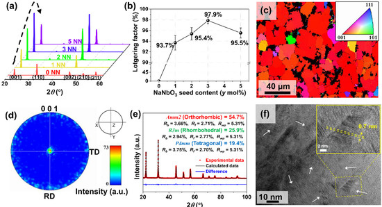
Figure 1.
(a) XRD patterns and (b) Lotgering factors of the NKNS-0.02SZ-0.02BAZ + y mol% NN thick films (0.0 ≤ y ≤ 5.0) sintered at 1090 °C for 3 h. (c) EBSD image, (d) (001) pole figure of the top surface, (e) Rietveld refinement of the XRD pattern, and (f) HRTEM image of the NKNS-0.02SZ-0.02BAZ + y mol% NN thick film with y = 3.0.

Table 1.
Parameters calculated from the Rietveld refinement of the XRD data of the NKNS-0.02SZ-0.02BAZ + y mol% NN thick film with x = 0.02 and y = 3.0.
Figure 2a–e display the SEM images of the cross-sectional fractured surface of the NKNS-0.02SZ-0.02BAZ + y mol% NN thick films (0.0 ≤ y ≤ 5.0). The untextured thick film (y = 0.0) has randomly oriented grains with an average grain size of 7.4 μm (Figure 2a). The grains begin to align along the [001] direction when 1.0 mol% NN seeds (y = 1.0) was used for texturing, but many of the grains were randomly oriented, as indicated by the arrows shown in Figure 2b. For the thick film with y = 2.0, many of the grains were textured, but a few remain untextured, as indicated by the arrows in Figure 2c, implying that the thick films (y = 1.0 and 2.0) have not been completely textured, although they show relatively large LF values close to 95%. All grains were well textured in the thick film with y = 3.0 (Figure 2d). The average grain size of this thick film was ~23 μm, implying that the NN seeds align the grains as well as increasing the grain size in the thick films. For the thick film with y = 5.0, most of the grains were textured, but the grain size slightly decreased, resulting in a decrease in the intensity of the (001) peak (Figure 1a), which induced a slight decrease in the LF (Figure 1b). The NN seeds behave as nuclei for grain growth and the formation of [001]-textured grains. As numerous NN seeds are present, the grains impinge each other during the growth process and inhibit the growth of the grains resulting in the formation of small grains. Therefore, the reduction in the grain size of the thick film with y = 5.0 can be attributed to the presence of a large amount of NN seeds. The SEM results confirm that 3.0 mol% NN seeds was the optimum quantity to texture the NKNS-0.02SZ-0.02BAZ thick film and that they can be used to texture other NKNS-(0.04−x)SZ-xBAZ thick films (0.0 ≤ x ≤ 0.04). In addition, rectangular-shaped holes were observed in the textured thick films, as indicated by the arrowheads shown in Figure 2c–e. These holes could be formed due to the diffusion of the NN seeds into the matrix. Similar results have been frequently observed in NKN-based thick films textured using NN seeds [8,9,10,24]. However, more study is required to clearly identify the formation mechanism of these holes.
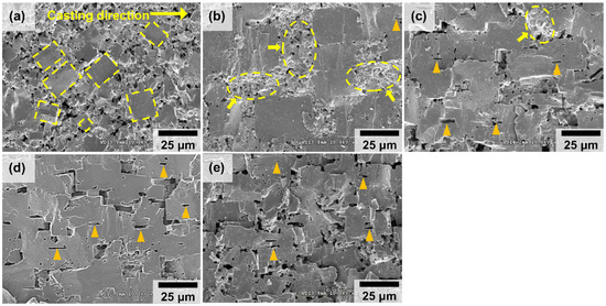
Figure 2.
SEM images of the cross-sectional fractured surface of the NKNS-0.02SZ-0.02BAZ + y mol% NN thick films with (a) y = 0.0, (b) y = 1.0, (c) y = 2.0, (d) y = 3.0, and (e) y = 5.0.
Polarization versus electric field (P-E) hysteresis curves were obtained for the NKNS-0.02SZ-0.02BAZ + y mol% NN thick films (0.0 ≤ y ≤ 5.0) to study the effect of texturing on the ferroelectric properties. Figure 3a,b show the P-E hysteresis curves obtained for the thick films with y = 0.0 and 3.0, respectively. The P-E hysteresis curves of the other thick films are displayed in Figure S3a–c. The spontaneous polarization (PS), remnant polarization (Pr), and coercive electric field (EC) of the thick film with y = 0.0 are 16.2 μC/cm2, 11.1 μC/cm2, and 0.59 kV/mm, respectively (Figure 3a). The PS value slightly increases to 16.7 μC/cm2 upon increasing y for the thick film with y = 3.0 (Figure 3b,c). The Pr value also increases with y, and the thick film with y = 3.0 showed a maximum Pr value of 13 μC/cm2. The increased Pr value can often be observed in textured piezoelectric ceramics due to the easy alignment of the polar vectors in textured thick films, which contributes to the increase in the piezoelectric properties of the textured thick films because the piezoelectric constant is proportional to the polarizability [7,11,25]. The increased grain size of the textured thick film also contributes to the increase in the PS and Pr values because the clamping of the domain walls decreases with an increase in the grain size due to the decrease in the grain boundary [26]. Moreover, the EC value was slightly reduced with an increase in y, as shown in Figure 3c, and the reduced EC was beneficial for the poling process. Therefore, the P-E curves indicate that the piezoelectric properties can be improved in the textured thick films; identical results have also been reported in previous studies [7,10,11]. In addition, the variation in the current density with respect to the electric field (J-E) was measured for the NKNS-0.02SZ-0.02BAZ + y mol% NN thick films (0.0 ≤ y ≤ 5.0) and Figure 3a,b show the J-E curves obtained for the thick films with y = 0.0 and 3.0, respectively. The J-E loops of the other thick films are also displayed in Figure S3a–c. All of the thick films show two peaks because of the conventional domain changing with the supply of an electric field. Hence, it can be proposed that they have normal ferroelectric properties. The εr values of the NKNS-0.02SZ-0.02BAZ + y mol% NN thick films (0.0 ≤ y ≤ 5.0) were measured at various temperatures. Figure 3d,e show the εr versus temperature plots obtained for the samples with y = 0.0 and 3.0, respectively. Furthermore, the εr versus temperature plots obtained for the other samples are shown in Figure S4a–c. The untextured thick film exhibits TC and TO-T peaks at 161 and 46 °C, respectively (Figure 3d), which slightly decrease upon increasing y, as shown in Figure 3e and Figure S4a–c, but this decrease was not significant. The slight decrease in TC and TO-T with an increase in the amount of NN seeds may be attributed to the slight difference in the chemical composition of the thick films because the NN seeds may not be completely and homogeneously diffused into the matrix of the thick films. In addition, the TC peak was slightly broadened after texturing because the relaxor properties increase with y, as shown in Figure S4d–h. A similar result has been observed in previous studies and attributed to the presence of stress between the NN seeds and matrix inducing the relaxor properties [8,11]. The dielectric loss (tan δ) curves of the thick films with y = 0.0 and 3.0 are similar, as shown in Figure 3d,e. However, the sample (y = 0.0) showed a relatively sharp peak near TC compared to that of the sample (y = 3.0) because the εr curve had a sharp peak near TC. Moreover, the tan δ values of the sample (y = 3.0) were slightly larger than those of the sample (y = 0.0) because of the presence of rectangular holes in the sample with y = 3.0.
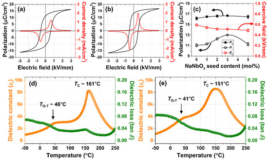
Figure 3.
P-E hysteresis curves obtained for the NKNS-0.02SZ-0.02BAZ + y mol% NN thick films with (a) y = 0.0, (b) y = 3.0. (c) PS, Pr, and EC of the NKNS-0.02SZ-0.02BAZ + y mol% NN thick films. The εr versus temperature curves obtained for the thick films with (d) y = 0.0 and (e) y = 3.0.
The relative densities, εT33/ε0, tan δ, kp, and d33 values of the NKNS-0.02SZ-0.02BAZ + y mol% NN thick films (0.0 ≤ y ≤ 5.0) are shown in Figure 4a. The relative densities slightly decrease upon increasing y, which was attributed to the rectangular holes formed in the textured thick films. However, the thick film with y = 3.0 has a comparatively high relative density of 93.5% of the theoretical density. A decrease in the density was occasionally observed in the textured thick films, but its effect on the piezoelectric properties was not significant [8,9,10,27]. The εT33/ε0 value of the untextured thick film (y = 0.0) was ~1803, which was enhanced upon increasing y for the thick film with y = 3.0 (εT33/ε0 = 2171) and a slightly reduced εT33/ε0 value of 2158 was observed in the thick film with y = 5.0. The variation in the εT33/ε0 value was similar to that of the grain size, indicating that the increased grain size may be responsible for the slight increase in the εT33/ε0 value observed for the textured thick films. The tan δ value of the untextured sample (y = 0.0) was ~3.3%, which slightly increased to 3.5–3.7% for the textured thick films, because of the existence of the rectangular holes produced via the diffusion of the NN seeds. However, the increase in the tan δ value was not significant and has been frequently observed in textured thick films [28,29,30]. The kp value of the untextured thick film was small (0.48) and increased upon increasing y. A maximum kp value of 0.58 was observed for the thick film with y = 3.0, which shows the highest degree of texture. However, the kp value decreased by 0.52 for the thick film with y = 5.0. The variation in the d33 value as a function of y was similar to that of the kp value; the d33 value of the untextured thick film was ~478 pC/N and a maximum d33 value of 760 ± 20 pC/N was observed for the thick film with y = 3.0. Figure 4b shows the d33 values of NKN-based piezoceramics reported in the literature and the maximum d33 value of the textured NKN-based thick film is 805 pC/N [8]. Hence, the d33 value of the textured NKNS-0.02SZ-0.02BAZ thick film developed in this study is similar to or slightly less than the largest d33 value. The above-mentioned results clearly show that the kp and d33 values were significantly improved when the thick film was textured. The thermal stability of the d33 value of the thick film with y = 3.0 was investigated and Figure 4c shows the d33 values measured at various temperatures. The d33 value slightly decreased upon increasing the temperature, but a comparatively large d33 value of 610 pC/N was observed at 110 °C. However, this value decreased significantly at temperatures >110 °C, possibly due to the TC of the thick film being close to 151 °C (Figure 3e). Therefore, the piezoelectricity of this thick film was stable up to 110 °C. Figure 4d shows the strain produced by an electric field in the untextured NKNS-0.02SZ-0.02BAZ and textured NKNS-0.02SZ-0.02BAZ + 3.0 mol% NN thick films. The untextured thick film exhibits low strain (0.12% at 4.0 kV/mm) and the textured thick film exhibits increased strain (0.16% at 4.0 kV/mm), indicating that texturing also increases the electric field-induced strain. The fatigue properties of the NKNS-0.02SZ-0.02BAZ + 3.0 mol% NN thick film were also investigated and the unipolar strain versus electric field (S-E) plots of the thick film were obtained after the application of different electric field cycles, as shown in Figure 4e. The inset of Figure 4e shows the electric field applied to the thick film. Because the maximum electric field (1.0 kV/mm) was larger than the EC of the thick film (~0.55 kV/mm), the applied electric field was large enough for the fatigue test [31]. Moreover, this strain was maintained after 106 cycles (Figure 4e). Therefore, it can be concluded that this thick film exhibits good fatigue properties.
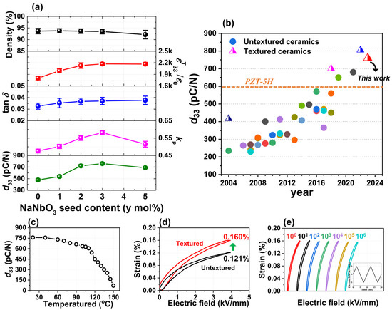
Figure 4.
(a) Relative densities, εT33/ε0, tan δ, kp, and d33 values of the NKNS-0.02SZ-0.02BAZ + y mol% NN thick films (0.0 ≤ y ≤ 5.0). (b) d33 values of NKN-based lead-free piezoceramics reported in the literature. (c) The d33 values measured at various temperatures for the thick film with y = 3.0. (d) Unipolar S-E curves obtained for the thick films with y = 0.0 and y = 3.0. (e) Unipolar S-E curves obtained for the thick film with y = 3.0 measured after the application of the electric field cycles.
The above-mentioned results show that 3.0 mol% NN seeds was an appropriate amount to produce the [001]-textured NKNS-0.02SZ-0.02BAZ thick film. Therefore, it was used to texture a series of NKNS-(0.04−x)SZ-xBAZ thick films (0.0 ≤ x ≤ 0.04) along the [001] direction. All of the NKNS-(0.04−x)SZ-xBAZ thick films (0.0 ≤ x ≤ 0.04) have a pure perovskite structure with high intensity (001) and (002) peaks (Figure 5a). Thus, the thick films have large LF values ranging between 95 and 98%, as shown in Figure 5b. Therefore, all of the thick films were textured using 3.0 mol% NN seeds. The SEM images of the thick films with x = 0.015 and 0.03 are shown in Figure 5c,d, respectively. The grains of these thick films were aligned along the [001] orientation with an average grain size of ~23 μm and also have dense microstructures. Similar microstructures were observed for the other thick films, as shown in Figure S5a–d and Figure 2d. Therefore, all of the thick films were textured using 3.0 mol% NN seeds with similar microstructures.
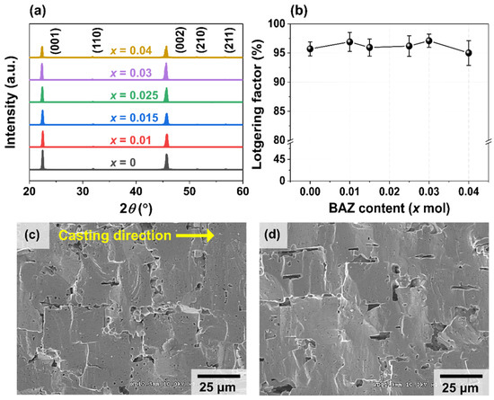
Figure 5.
(a) XRD patterns and (b) Lotgering factors of the textured NKNS-(0.04−x)SZ-xBAZ thick films (0.0 ≤ x ≤ 0.04). SEM images of the textured NKNS-(0.04−x)SZ-xBAZ thick films with (c) x = 0.015 and (d) x = 0.03.
The crystal structures of the textured NKNS-(0.04−x)SZ-xBAZ thick films (0.0 ≤ x ≤ 0.04) were investigated and the results of the Rietveld refinement of their XRD patterns are shown in Figure 6a–d. Table 2 lists the parameters calculated from the Rietveld refinement of the XRD data of the thick films. The textured thick film with x = 0.0 shows an R-O-T structure consisting of R3m rhombohedral (26.2%), Amm2 orthorhombic (65.7%), and P4mm tetragonal (8.1%) structures (Figure 6a). Because the proportion of the P4mm tetragonal structure was small, the crystal structure of the thick film was close to that of the R-O structure. In addition, the Rwp value of the R-O model was slightly larger than that of the R-O-T model (Figure S6). Therefore, the structure of the thick film with x = 0.0 was very similar to the R-O structure. The R-O-T structure was also observed in the textured thick films with x = 0.01, 0.03, and 0.02, as shown in Figure 6b,c, and Figure 1e, respectively. As x increases, the proportion of the T structure increases, whereas that of the O structure decreases. However, the change in the proportion of the R structure was not significant. Finally, the O structure disappears in the thick film with x = 0.04 and an R-T structure with R3m rhombohedral (27.9%) and P4mm tetragonal (72.1%) structures was formed, as shown in Figure 6d. The proportions of the R, O, and T structures for each textured thick film are listed in Table 3.
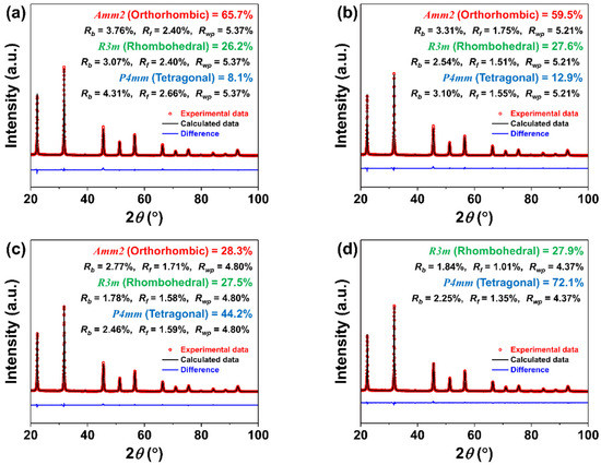
Figure 6.
Rietveld refinement of the XRD patterns obtained for the textured NKNS-(0.04−x)SZ-xBAZ thick films with (a) x = 0.0, (b) x = 0.01, (c) x = 0.03, and (d) x = 0.04.

Table 2.
Parameters calculated from Rietveld refinement of the XRD data of the textured NKNS-(0.04−x)SZ-xBAZ thick films (0.0 ≤ x ≤ 0.04).

Table 3.
Proportions of the R, O, and T structures in the textured NKNS-(0.04−x)SZ-xBAZ thick films (0.0 ≤ x ≤ 0.04).
Figure 7a–d exhibit the εr versus temperature plots obtained for the NKNS-(0.04−x)SZ-xBAZ thick films (0.0 ≤ x ≤ 0.04). The thick film with x = 0.0 shows TR-O and TO-T at approximately 0 and 75 °C, respectively (Figure 7a). The TO-T decreases and TR-O slightly increases with an increase in x, as shown in Figure 7b–d, and they encounter at ~29 °C in the thick film with x = 0.03 and form the TR-O-T, as shown in Figure 7c. Therefore, the above-mentioned results also imply that the thick films (0.0 ≤ x ≤ 0.03) have an R-O-T structure. Finally, the TR-O-T changes to TR-T for the thick film with x = 0.04 due to the disappearance of the O structure (Figure 7d), suggesting that this thick film has an R-T structure. The TC of the thick film with x = 0 was ~144 °C, which increases upon increasing x to 171 °C for the thick film with x = 0.04. The results of the εr versus temperature curves also suggest that as x increases, the T structure increases and the O structure decreases, but the change in the R structure was not significant. Hence, the crystal structure of the thick films changes from R-O-T to R-T upon increasing x. The P-E hysteresis curves and J-E loops obtained for the thick films were also studied (Figure S7a–f). The variations in the Pr and EC values were not significant for the thick films with x ≤ 0.02, but the Pr value decreased and the EC value increased upon increasing x for the thick films with x > 0.02, as shown in Figure S7g, which can be attributed to the increase in the proportion of the T structure. In addition, all of the thick films exhibit two peaks in the J-E loops, confirming that they have normal ferroelectric characteristics. Figure 8a shows the relative densities, εT33/ε0, tan δ, kp, and d33 values of the textured NKNS-(0.04−x)SZ-xBAZ thick films (0.0 ≤ x ≤ 0.04). The relative densities of the thick films were slightly low, which are ~93–94% of the theoretical density, possibly due to the presence of rectangular holes. The εT33/ε0 value of the thick film with x = 0.0 was 1915, which slightly increased upon increasing x to 2312 for the thick film with x = 0.04, which can be attributed to the decrease in TO-T with an increase in x, leading to the presence of TR-O-T (or TR-T) near RT. The tan δ values of the thick films with (0.0 ≤ x ≤ 0.025) were similar (3.5–3.8%) and slightly increased to 4.5–5.0% for the thick films with x = 0.03 and 0.04, but this increase was not significant. The kp value of the thick film (x = 0.0) was 0.5, which increased upon increasing x. The largest kp value (0.58) was obtained for the thick film with x = 0.02, which decreased when x was > 0.02. The variation in the d33 value is shown in Figure 8a. The thick film with x = 0.0 showed a d33 value of 535 pC/N, which increased with increasing x to 760 ± 20 pC/N for the thick film with x = 0.02.
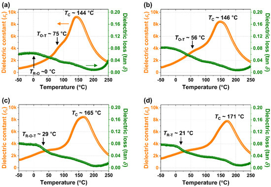
Figure 7.
The εr versus temperature curves obtained for the textured NKNS-(0.04−x)SZ-xBAZ thick films with (a) x = 0.0, (b) x = 0.01, (c) x = 0.03, and (d) x = 0.04.
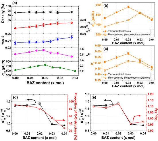
Figure 8.
(a) Relative densities, εT33/ε0, tan δ, kp and d33 values of the textured NKNS-(0.04−x)SZ-xBAZ thick films (0.0 ≤ x ≤ 0.04). (b) The d33 values and (c) kp values of the textured NKNS-(0.04−x)SZ-xBAZ thick films and untextured piezoelectric ceramics with 0.0 ≤ x ≤ 0.04. (d) Proportion of the R-O structure and d33T/d33UT values of the NKNS-(0.04−x)SZ-xBAZ thick films (0.0 ≤ x ≤ 0.04). (e) d15/d33 of the NKNS-(0.04−x)SZ-xBAZ piezoelectric ceramics and d33T/d33UT of the NKNS-(0.04−x)SZ-xBAZ thick films (0.0 ≤ x ≤ 0.04).
However, the d33 value decreased when x was > 0.02. Hence, it can be proposed that the variation in d33 with respect to x was similar to the kp value. Moreover, the highest piezoelectricity (d33 = 760 ± 20 pC/N and kp = 0.58) was observed for the textured thick film with x = 0.02. According to a previous study, an untextured piezoelectric ceramic with x = 0.03 showed the largest piezoelectricity (d33 = 650 pC/N and kp = 0.5) [20]. However, the textured thick film with x = 0.03 showed a slightly reduced d33 value of ~638 pC/N with a slightly increased kp value of 0.52, indicating that the increase in the piezoelectricity of this thick film was not significant after texturing. The increase in the piezoelectricity after texturing was investigated for the NKNS-(0.04−x)SZ-xBAZ thick films (0.0 ≤ x ≤ 0.04). Figure 8b shows the d33 values of the textured NKNS-(0.04−x)SZ-xBAZ thick films and untextured piezoelectric ceramics with 0.0 ≤ x ≤ 0.04. The d33 values of the textured thick films were much larger than those of untextured piezoelectric ceramics for the samples with 0.0 ≤ x ≤ 0.02; the d33 values of the textured thick films were ~1.55 times larger than those of the untextured piezoelectric ceramics. However, the d33 values of the textured thick films were similar to those of the untextured piezoelectric ceramics for the samples with x = 0.03 and 0.04, indicating that the d33 value was not improved after texturing. The kp values of the textured thick films and untextured piezoelectric ceramics were also studied (Figure 8c). The kp values of the textured thick films were much larger than those of the untextured piezoelectric ceramics for the samples with 0.0 ≤ x ≤ 0.02. However, for the samples with x = 0.03 and 0.04, the enhancement in the kp value after texturing was not significant. Hence, the d33 and kp values show a similar trend; the effect of texturing on the piezoelectricity was very large for thick films with 0.0 ≤ x ≤ 0.02, but it was insignificant when x was >0.02. In general, the piezoelectricity of the [001]-textured thick film was significantly improved when it had an O or R structure [7,8,11,32]. However, when the [001]-textured thick film had a T structure, the effect of texturing on its piezoelectricity was small [11,12,13]. Figure 8d shows the proportion of the O and R structures in the textured thick films and the d33T/d33UT values, where d33T and d33UT are the d33 values of the textured thick films and the untextured piezoelectric ceramics, respectively. The proportion of the R-O structure was > 80% in the thick films with 0.0 ≤ x ≤ 0.02, which show a large d33T/d33UT value of ~1.55. However, a small d33T/d33UT value (<1.0) was observed for the thick films with x = 0.03 and 0.04, which was attributed to the proportion of the R-O structure being small (<56%) or the proportion of the T structure being large. Identical results were observed for the kp values (Figure S8). According to previous studies, the d33 value of an NKN-based piezoelectric ceramic with a R-O structure is ~300 pC/N (or 355 pC/N), which increased to 700 pC/N (or 620 pC/N) after texturing, indicating that the d33T/d33UT value is ~2.3 (or 1.7) [7,10]. Therefore, the d33T/d33UT value of the textured NKNS-0.02SZ-0.02BAZ thick film (~1.55), which has an R-O-T multi-structure and a large proportion of the R-O structure (81%), was slightly smaller than that of the textured thick films with the R-O structure. However, the d33 value of the NKNS-0.02SZ-0.02BAZ untextured ceramic with R-O-T structure (~478 pC/N) was much larger than those of the untextured ceramics with R-O structures (300–355 pC/N). Therefore, the d33 value of the textured NKNS-0.02SZ-0.02BAZ thick film (760 ± 20 pC/N) was larger than those of the textured thick films with R-O structures (620–700 pC/N) [7,10], although the d33T/d33UT value of the former thick film with the R-O-T structure was slightly smaller than that of the latter thick film with an R-O multi-structure. Therefore, it can be proposed that NKN-based piezoelectric ceramics with R-O-T structures with a large proportion of the R-O phase (>80%) may be optimal lead-free piezoelectric ceramics to increase the piezoelectricity using the RTGG method.
Piezoelectric single crystals with O and R structures, which are grown along polar directions, generally show large d15/d33 values (or shear piezoelectric constants) when subjected to an applied electric field along the polar direction [33]. When these single crystals are grown along the [001] direction, they showed a large d33 value when the electric field was supplied along the [001] direction due to the large shear piezoelectric constant (d15/d33 value), which induces the easy rotation of PSs (Figure S9a,b) [13,34,35,36]. In addition, the d15/d33 value of a single crystal with a T structure is relatively small [37]. This concept can be applied to [001]-textured piezoelectric thick films with multi-structures because the [001]-textured thick films are similar to single crystals grown along the [001] direction. When the piezoelectric ceramic with a multi-structure has a large d15/d33 value, the proportion of O and R structures can be large in this piezoelectric ceramic. Furthermore, a piezoelectric ceramic with a large d15/d33 value is expected to have a large d33 value when it is textured along the [001] direction because of the easy rotation of the PSs (Figure S9a,b) [38]. To confirm this hypothesis, the d15/d33 values of the NKNS-(0.04−x)SZ-xBAZ piezoelectric ceramics (0.0 ≤ x ≤ 0.04) have been measured and compared with the d33T/d33UT values, as shown in Figure 8e. The variation in d15/d33 was very similar to that of d33T/d33UT. Therefore, it can be concluded that piezoelectric ceramics with large d15/d33 values can have large d33T/d33UT values after the texturing process. Moreover, the d15/d33 value can be used to prepare piezoelectric ceramics, which can have large d33T values after texturing.
4. Conclusions
The NKNS-0.02SZ-0.02BAZ thick film was textured using 3.0 mol% NN seeds with a high LF of 98%. This thick film had an R-O-T structure with a large proportion of the R-O structure (>80%) and a dense microstructure with large grains (~23 μm). Nanodomains (0.7 nm in width and 6 nm in length) were developed in this thick film after texturing. The d33 and kp values of the untextured NKNS-0.02SZ-0.02BAZ thick film were 478 pC/N and 0.48, respectively, and the textured thick film obtained using 3.0 mol% NN seeds showed increased d33 (760 ± 20 pC/N) and kp (0.58) values. A large d33 value of 610 pC/N was maintained at 110 °C because the TC of the thick film was relatively high (151 °C), indicating that the piezoelectricity of the thick film was stable up to 110 °C. This thick film showed a large electric-field-induced strain of 0.16% at 4.0 kV/mm, which was maintained after 106 electric field cycles, indicating that the textured thick film has good fatigue properties. Then, 3.0 mol% NN seeds were added to texture a series of NKNS-(0.04−x)SZ-xBAZ thick films with 0.0 ≤ x ≤ 0.04. After texturing, the increases in the d33 and kp values of the thick films were significant when x ≤ 0.02, because the resulting thick films had an R-O-T structure with a large proportion of the R-O structure (>80%). However, the increases in the d33 and kp values after texturing were insignificant because of the presence of a small proportion of the R-O structure (<56%) or a large proportion of the T structure (>44%) when x > 0.02. Thus, the large d33 (760 ± 20 pC/N) and kp (0.58) values obtained in the textured NKNS-0.02SZ-0.02BAZ thick film can be explained by the large crystallographic texturing, the R-O-T structure with a large proportion of the R-O structure, which results in four <110> and four <111> domain configurations, and the presence of nanodomains. In addition, the piezoelectric ceramic with a large d15/d33 value shows a large d33 value after [001] texturing because of the easy rotation of the spontaneous polarizations. Hence, the d15/d33 value can be used to select piezoelectric ceramics that yield large d33 values after [001] texturing.
Supplementary Materials
The following supporting information can be downloaded at: https://www.mdpi.com/article/10.3390/act12020066/s1.
Author Contributions
Conceptualization, S.-H.G. and D.-S.K.; Data curation, S.-H.G. and S.-J.P.; Formal analysis, S.-H.G., D.-S.K. and E.-J.K.; Funding acquisition, S.N.; Investigation, Y.-G.C., S.-J.C., H.-M.Y. and B.-J.K.; Methodology, S.-H.G. and D.-S.K.; Project administration, S.N.; Resources, J.-H.L. and S.N.; Software, S.-H.G.; Supervision, S.N.; Validation, S.-H.G. and D.-S.K.; Visualization, S.-H.G.; Writing—original draft, S.-H.G., D.-S.K. and S.N.; Writing—review and editing, S.-H.G. All authors have read and agreed to the published version of the manuscript.
Funding
This study was supported by a Technology Innovation Program of MOTIE/KEIT grant funded by the Ministry of Trade, Industry and Energy (MOTIE, Korea) [Project No. 20008775, Development of display integrated surface vibration and eco-friendly Pb-free piezoelectric materials and application technology].
Institutional Review Board Statement
Not applicable.
Informed Consent Statement
Not applicable.
Data Availability Statement
Not applicable.
Acknowledgments
We also thank the LG Display Co. Ltd. For the Industry–University Cooperative Research Project.
Conflicts of Interest
The authors declare no conflict of interest.
References
- Zhang, Y.; Li, J.-F. Review of chemical modification on potassium sodium niobate lead-free piezoelectrics. J. Mater. Chem. C 2019, 7, 4284–4303. [Google Scholar] [CrossRef]
- Zhang, N.; Zheng, T.; Wu, J. Lead-free (K, Na)NbO3-based materials: Preparation techniques and piezoelectricity. ACS Omega 2020, 5, 3099–3107. [Google Scholar] [CrossRef] [PubMed]
- Thong, H.-C.; Zhao, C.; Zhou, Z.; Wu, C.-F.; Liu, Y.-X.; Du, Z.-Z.; Li, J.-F.; Gong, W.; Wang, K. Technology transfer of lead-free (K, Na)NbO3-based piezoelectric ceramics. Mater. Today 2019, 29, 37–48. [Google Scholar] [CrossRef]
- Saito, Y.; Takao, H.; Tani, T.; Nonoyama, T.; Takatori, K.; Homma, T.; Nagaya, T.; Nakamura, M. Lead-free piezoceramics. Nature 2004, 432, 84–87. [Google Scholar] [CrossRef] [PubMed]
- Messing, G.L.; Trolier-McKinstry, S.; Sabolsky, E.; Duran, C.; Kwon, S.; Brahmaroutu, B.; Park, P.; Yilmaz, H.; Rehrig, P.; Eitel, K. Templated grain growth of textured piezoelectric ceramics. Crit. Rev. Solid State Mater. Sci. 2004, 29, 45–96. [Google Scholar] [CrossRef]
- Gao, L.; Dursun, S.; Gurdal, A.E.; Hennig, E.; Zhang, S.; Randall, C.A. Atmospheric controlled processing enabling highly textured NKN with enhanced piezoelectric performance. J. Eur. Ceram. Soc. 2019, 39, 963–972. [Google Scholar] [CrossRef]
- Li, P.; Zhai, J.; Shen, B.; Zhang, S.; Li, X.; Zhu, F.; Zhang, X. Ultrahigh piezoelectric properties in textured (K, Na)NbO3-based lead-free ceramics. Adv. Mater. 2018, 30, 1705171. [Google Scholar] [CrossRef]
- Go, S.-H.; Kim, H.; Kim, D.-S.; Eum, J.-M.; Chae, S.-J.; Kim, E.-J.; Nahm, S. Improvement of piezoelectricity of (Na, K) Nb-based lead-free piezoceramics using [001]-texturing for piezoelectric energy harvesters and actuators. J. Eur. Ceram. Soc. 2022, 42, 6478–6492. [Google Scholar] [CrossRef]
- Chae, S.-J.; Kim, D.-S.; Kim, H.; Go, S.-H.; Kim, S.-W.; Kim, E.-J.; Eum, J.-M.; Kim, I.-S.; Nahm, S. Structural and piezoelectric properties of textured NLKNS-CZ thick films and their application in planar piezoactuator. J. Am. Ceram. Soc. 2022, 105, 1185–1197. [Google Scholar] [CrossRef]
- Kim, D.-S.; Eum, J.-M.; Go, S.-H.; Shin, H.-S.; Kim, H.; Chae, S.-J.; Kim, S.-W.; Kim, E.-J.; Woo, J.-U.; Nahm, S. Remarkable piezoelectric performance and good thermal stability of [001]-textured 0.96(K0.5Na0.5)(Nb1-ySby)O3-0.04SrZrO3 lead-free piezoelectric ceramics. J. Alloys Compd. 2021, 882, 160662. [Google Scholar] [CrossRef]
- Liu, Y.; Chang, Y.; Li, F.; Yang, B.; Sun, Y.; Wu, J.; Zhang, S.; Wang, R.; Cao, W. Exceptionally high piezoelectric coefficient and low strain hysteresis in grain-oriented (Ba, Ca)(Ti, Zr)O3 through integrating crystallographic texture and domain engineering. ACS Appl. Mater. Interfaces 2017, 9, 29863–29871. [Google Scholar] [CrossRef]
- Li, F.; Zhang, S.; Xu, Z.; Wei, X.; Luo, J.; Shrout, T.R. Composition and phase dependence of the intrinsic and extrinsic piezoelectric activity of domain engineered (1− x) Pb (Mg1/3Nb2/3)O3− x PbTiO3 crystals. J. Appl. Phys. 2010, 108, 034106. [Google Scholar] [CrossRef]
- Li, F.; Zhang, S.; Lin, D.; Luo, J.; Xu, Z.; Wei, X.; Shrout, T.R. Electromechanical properties of Pb(In1/2Nb1/2)O3-Pb(Mg1/3Nb2/3)O3-PbTiO3 single crystals. J. Appl. Phys. 2011, 109, 014108. [Google Scholar] [CrossRef]
- Zhang, B.; Wu, J.; Wang, X.; Cheng, X.; Zhu, J.; Xiao, D. Rhombohedral–orthorhombic phase coexistence and electrical properties of Ta and BaZrO3 co-modified (K, Na)NbO3 lead-free ceramics. Curr. Appl. Phys. 2013, 13, 1647–1650. [Google Scholar] [CrossRef]
- Xue, D.; Shi, M.; Chen, Y.; Liu, K.; Chen, Z.; Jiang, X. Piezoelectric and dielectric properties of lead-free 0.96(K0.48Na0.535)0.96Li0.04Nb1-xSbxO3-0.04CaZrO3 ceramics with rhombohedral–orthorhombic phase boundary. Ferroelectrics 2017, 514, 1–8. [Google Scholar] [CrossRef]
- Zuo, R.; Fu, J.; Lv, D.; Liu, Y. Antimony tuned rhombohedral-orthorhombic phase transition and enhanced piezoelectric properties in sodium potassium niobate. J. Am. Ceram. Soc. 2010, 93, 2783–2787. [Google Scholar] [CrossRef]
- Tao, H.; Wu, H.; Liu, Y.; Zhang, Y.; Wu, J.; Li, F.; Lyu, X.; Zhao, C.; Xiao, D.; Zhu, J. Ultrahigh performance in lead-free piezoceramics utilizing a relaxor slush polar state with multiphase coexistence. J. Am. Chem. Soc. 2019, 141, 13987–13994. [Google Scholar] [CrossRef]
- Go, S.-H.; Kim, D.-S.; Eum, J.-M.; Shin, H.-S.; Chae, S.-J.; Kim, S.-W.; Kim, E.-J.; Woo, J.-U.; Nahm, S. Excellent piezoelectric properties of (K, Na)(Nb, Sb)O3-CaZrO3-(Bi, Ag)ZrO3 lead-free piezoceramics. J. Alloys Compd. 2021, 889, 161817. [Google Scholar] [CrossRef]
- Zhou, C.; Zhang, J.; Yao, W.; Liu, D.; He, G. Remarkably strong piezoelectricity, rhombohedral-orthorhombic-tetragonal phase coexistence and domain structure of (K, Na)(Nb, Sb)O3–(Bi, Na)ZrO3–BaZrO3 ceramics. J. Alloys Compd. 2020, 820, 153411. [Google Scholar] [CrossRef]
- Go, S.-H.; Eum, J.-M.; Kim, D.-S.; Chae, S.-J.; Kim, S.-W.; Kim, E.-J.; Chae, Y.-G.; Woo, J.-U.; Nahm, S. Piezoelectricity of (K, Na)(Nb, Sb)O3–SrZrO3–(Bi, Ag)ZrO3 piezoceramics and their application in planar-type actuators. J. Mater. Chem. C 2021, 9, 16741–16750. [Google Scholar] [CrossRef]
- Yan, Y.; Liu, D.; Zhao, W.; Zhou, H.; Fang, H. Topochemical synthesis of a high-aspect-ratio platelet NaNbO3 template. J. Am. Ceram. Soc. 2007, 90, 2399–2403. [Google Scholar] [CrossRef]
- Chang, Y.; Yang, Z.; Chao, X.; Liu, Z.; Wang, Z. Synthesis and morphology of anisotropic NaNbO3 seed crystals. Mater. Chem. Phys. 2008, 111, 195–200. [Google Scholar] [CrossRef]
- Li, P.; Liu, B.; Shen, B.; Zhai, J.; Zhang, Y.; Li, F.; Liu, X. Mechanism of significantly enhanced piezoelectric performance and stability in textured potassium-sodium niobate piezoelectric ceramics. J. Eur. Ceram. Soc. 2018, 38, 75–83. [Google Scholar] [CrossRef]
- Kimura, T.; Yi, Y.; Sakurai, F. Mechanisms of texture development in lead-free piezoelectric ceramics with perovskite structure made by the templated grain growth process. Materials 2010, 3, 4965–4978. [Google Scholar] [CrossRef] [PubMed]
- Kou, Q.; Yang, B.; Sun, Y.; Yang, S.; Liu, L.; Xie, H.; Chang, Y.; Zhang, S.; Li, F. Tetragonal (Ba, Ca)(Zr, Ti)O3 textured ceramics with enhanced piezoelectric response and superior temperature stability. J. Mater. 2022, 8, 366–374. [Google Scholar] [CrossRef]
- Cai, W.; Fu, C.; Gao, J.; Chen, H. Effects of grain size on domain structure and ferroelectric properties of barium zirconate titanate ceramics. J. Alloys Compd. 2009, 480, 870–873. [Google Scholar] [CrossRef]
- Hussain, A.; Maqbool, A.; Kim, J.S.; Song, T.K.; Kim, M.H.; Kim, W.J.; Kim, S.S. Sodium excess Ta-Modified (K0.5Na0.5)NbO3 ceramics prepared by reactive template grain growth method. Int. J. Appl. Ceram. Technol. 2015, 12, 228–234. [Google Scholar] [CrossRef]
- Gupta, S.; Belianinov, A.; Okatan, M.B.; Jesse, S.; Kalinin, S.V.; Priya, S. Fundamental limitation to the magnitude of piezoelectric response of ⟨001⟩pc textured K0.5Na0.5NbO3 ceramic. Appl. Phys. Lett. 2014, 104, 172902. [Google Scholar] [CrossRef]
- Liu, B.; Li, P.; Shen, B.; Zhai, J.; Zhang, Y.; Li, F.; Liu, X. Enhanced piezoelectric properties and temperature-insensitive strain behavior of <001>-textured KNN-based ceramics. Ceram. Int. 2017, 43, 8004–8009. [Google Scholar] [CrossRef]
- Li, L.; Bai, W.; Zhang, Y.; Shen, B.; Zhai, J. The preparation and piezoelectric property of textured KNN-based ceramics with plate-like NaNbO3 powders as template. J. Alloys Compd. 2015, 622, 137–142. [Google Scholar] [CrossRef]
- Weitzing, H.; Schneider, G.; Steffens, J.; Hammer, M.; Hoffmann, M. Cyclic fatigue due to electric loading in ferroelectric ceramics. J. Eur. Ceram. Soc. 1999, 19, 1333–1337. [Google Scholar] [CrossRef]
- Chang, Y.; Watson, B.; Fanton, M.; Meyer, R.J.M.; Messing, G.L., Jr. Enhanced texture evolution and piezoelectric properties in CuO-doped Pb(In1/2Nb1/2)O3-Pb(Mg1/3Nb2/3)O3-PbTiO3 grain-oriented ceramics. Appl. Phys. Lett. 2017, 111, 232901. [Google Scholar] [CrossRef]
- Davis, M.; Budimir, M.; Damjanovic, D.; Setter, N. Rotator and extender ferroelectrics: Importance of the shear coefficient to the piezoelectric properties of domain-engineered crystals and ceramics. J. Appl. Phys. 2007, 101, 054112. [Google Scholar] [CrossRef]
- Park, S.-E.; Shrout, T.R. Relaxor based ferroelectric single crystals for electro-mechanical actuators. Mater. Res. Innov. 1997, 1, 20–25. [Google Scholar] [CrossRef]
- Zhang, R.; Cao, W. Transformed material coefficients for single-domain 0.67Pb(Mg1∕3Nb2∕3)O3–0.33PbTiO3 single crystals under differently defined coordinate systems. Appl. Phys. Lett. 2004, 85, 6380–6382. [Google Scholar] [CrossRef]
- Zgonik, M.; Schlesser, R.; Biaggio, I.; Voit, E.; Tscherry, J.; Günter, P. Materials constants of KNbO3 relevant for electro-and acousto-optics. J. Appl. Phys. 1993, 74, 1287–1297. [Google Scholar] [CrossRef]
- Zheng, L.; Wang, J.; Liu, X.; Yang, L.; Lu, X.; Li, Y.; Huo, D.; Lü, W.; Yang, B.; Cao, W. Tetragonal (K, Na)NbO3 based lead-free single crystal: Growth, full tensor properties, and their orientation dependence. Appl. Phys. Lett. 2017, 111, 172903. [Google Scholar] [CrossRef]
- Li, F.; Zhang, S.; Xu, Z.; Wei, X.; Shrout, T.R. Critical property in relaxor-PbTiO3 single crystals–shear piezoelectric response. Adv. Funct. Mater. 2011, 21, 2118–2128. [Google Scholar] [CrossRef]
Disclaimer/Publisher’s Note: The statements, opinions and data contained in all publications are solely those of the individual author(s) and contributor(s) and not of MDPI and/or the editor(s). MDPI and/or the editor(s) disclaim responsibility for any injury to people or property resulting from any ideas, methods, instructions or products referred to in the content. |
© 2023 by the authors. Licensee MDPI, Basel, Switzerland. This article is an open access article distributed under the terms and conditions of the Creative Commons Attribution (CC BY) license (https://creativecommons.org/licenses/by/4.0/).