1. Introduction
Functional materials change their physical properties in response to electric and magnetic fields. Highly reproducible and reversible materials can be easily applied to mechatronics elements. Many studies have been carried out on devices using functional fluids with dispersed microparticles such as electro-rheological (ER) fluids, magneto-rheological (MR) fluids, ferrofluids, and magnetic powders [
1,
2,
3,
4,
5]. Our group has also conducted several studies on clutches, actuators, dampers, and brakes using ER fluids [
6,
7].
It is necessary to install a seal in the driving part of the equipment using these fluids to prevent leakage and contamination. However, because all of the functional fluids are made by dispersing tiny particles in oil, a problem occurs in which the particles can enter between the lip of the seal and the sliding part, damage the seal, and increase leakage. In addition, the specific gravity of the dispersed particles is the same as or higher than that of the dispersant, so the particles will settle and, in some cases, agglomerate. This reduces the original performance of the equipment, making it necessary to re-disperse the particles by running the equipment before use.
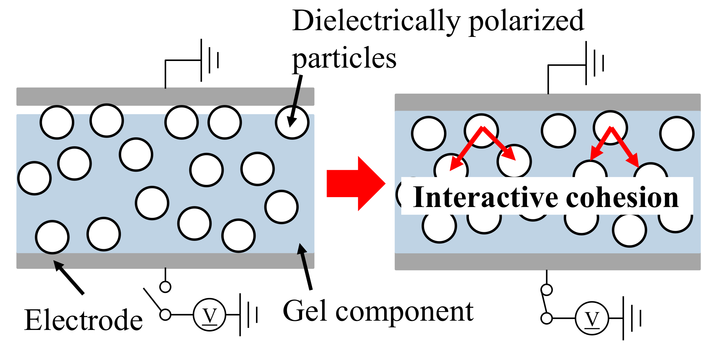
However, in an electro-adhesive (EA) gel, which is an elastomerized ER fluid, the particles are semi-fixed in the dispersant. Therefore, they do not cause problems such as leakage, seal breakage, or particle sedimentation as in functional fluids, although a seal or shielded bearing is necessary to prevent foreign substances. This also allows greater flexibility in design in that they do not need to be attached to a rigid body because of their flexibility. Taking advantage of these characteristics, we developed controllable actuators and brakes with new structures by attaching EA gels to flat or curved surfaces [
8,
9,
10,
11,
12,
13,
14,
15]. We also developed a linear brake that resists the translational motion of an electrode plate with an attached EA material [
16].
Although various case studies have revealed many characteristics of devices with EA gels, the findings are still individual and have not been unified. Because EA gel works by shearing while it is sandwiched between the electrodes and is under an electric field, how it contacts with the electrodes essentially affects the shear stress between the electrode and it. Since the electrode will inevitably have a curved surface especially when the electrode is attached to a flexible or non-planar body, the contact condition will be different from that on a flat rigid body. As detailed in
Section 2.1, the contact force, or the surface pressure, between the electrode and the EA gel is important for the contact condition. However, the curvature direction of the electrodes and the shearing direction of the EA gel may or may not coincide, especially for curved surfaces, as detailed in
Section 2.2. They may have different surface pressure characteristics and different effects on the performance of the EA gel device because of different contact conditions. Thus, it is important to clarify the relations between the shear stress, the curvature and shear stress directions, and the surface pressure of the EA gel. They, however, have never actually been studied comprehensively or systematically.
In this paper, we summarize research results on transmission/braking elements with EA gel on curved surfaces, especially in terms of the initial pressure on the EA gel surface. We found that even an EA gel attached to a curved surface can be used as a stable and controllable transmission/braking element if the structure provides a stable surface pressure of about 1 kPa to the EA gel surface.
These results can be applied to non-fluid functional materials other than EA gel. MR and magnetic particles have been mixed into rubber and applied to functional shock absorbers and seismic isolators [
17,
18,
19,
20]. These are currently used to change the hardness of a rubber attenuator. In the future, when they are used to change the adsorption force and surface friction to be the same as that of the EA gel, their characteristics can be discussed in the same terms as in this study. The findings of this paper contribute to increasing the degrees of freedom in designing devices with functional materials. That is, even devices with flexible and soft structures are effective as long as they satisfy the pressure requirements. This will lead to the development of flexible and soft actuators and robots.
Some of the equipment presented in
Section 3 to
Section 5 was taken from the references as follows:
Section 3: [
10] This study designed a clutch and linear actuator using EA gel and measured the generated force. The surface pressure was mentioned only for one EA gel sheet in a plane, where the clutch torque was analyzed when the surface pressure was relatively high [
13]. This study used clutches and linear actuators with up to 34 EA gel sheets to measure the generated forces, but the surface pressure was not considered.
Section 4: [
15] We tried developing a force display suit using EA gel sheets with different curvature and shear stress directions. A uniform surface pressure was also tried. However, only one EA gel sheet was used, which did not show how uniform surface pressure would behave with many gel sheets.
Section 5: [
11,
12] A belt drive mechanism using EA gel was developed in these studies, where the curvature direction and the shear stress direction were the same. These papers verified the belt drive mechanism, but did not deal specifically with the surface pressure of the EA gel.
Most of the experimental results, however, are newly presented. In addition, the effect of surface curvature on the EA gel is newly investigated in
Section 6.
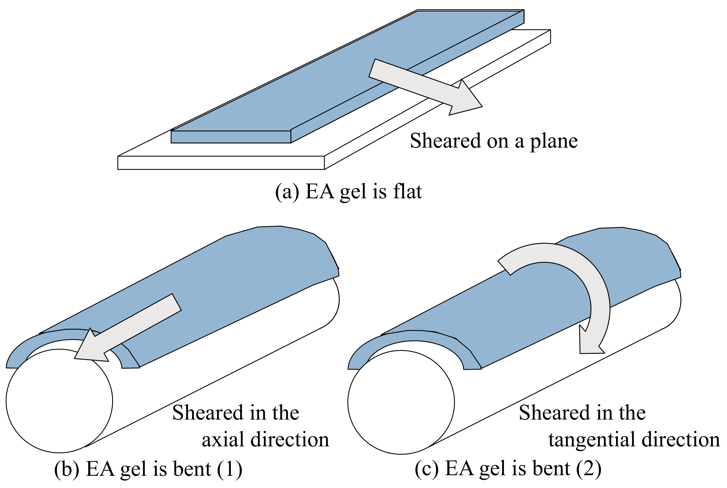
4. EA Gel Is Curved Orthogonally to the Shear Direction
This section corresponds to
Figure 4b.
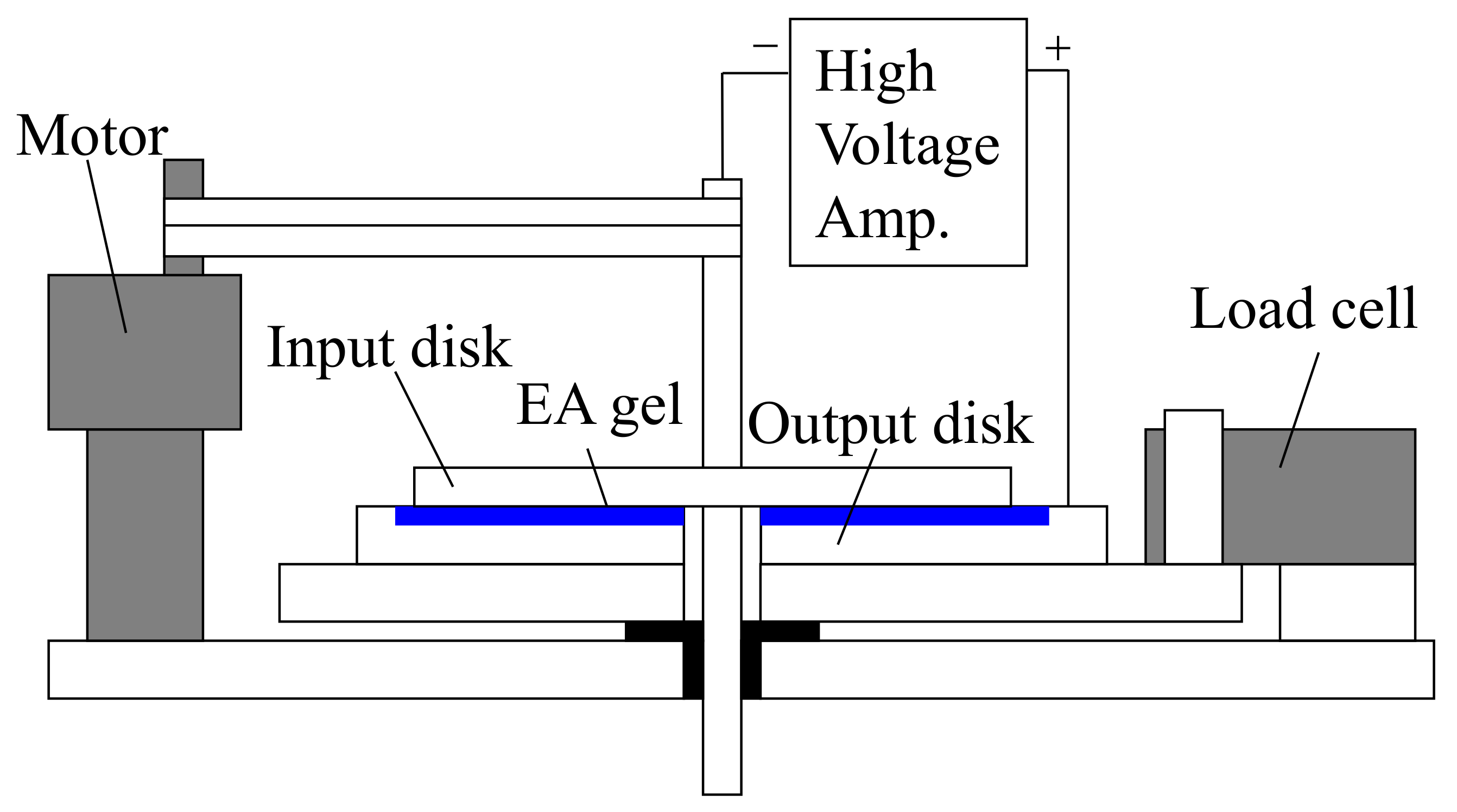
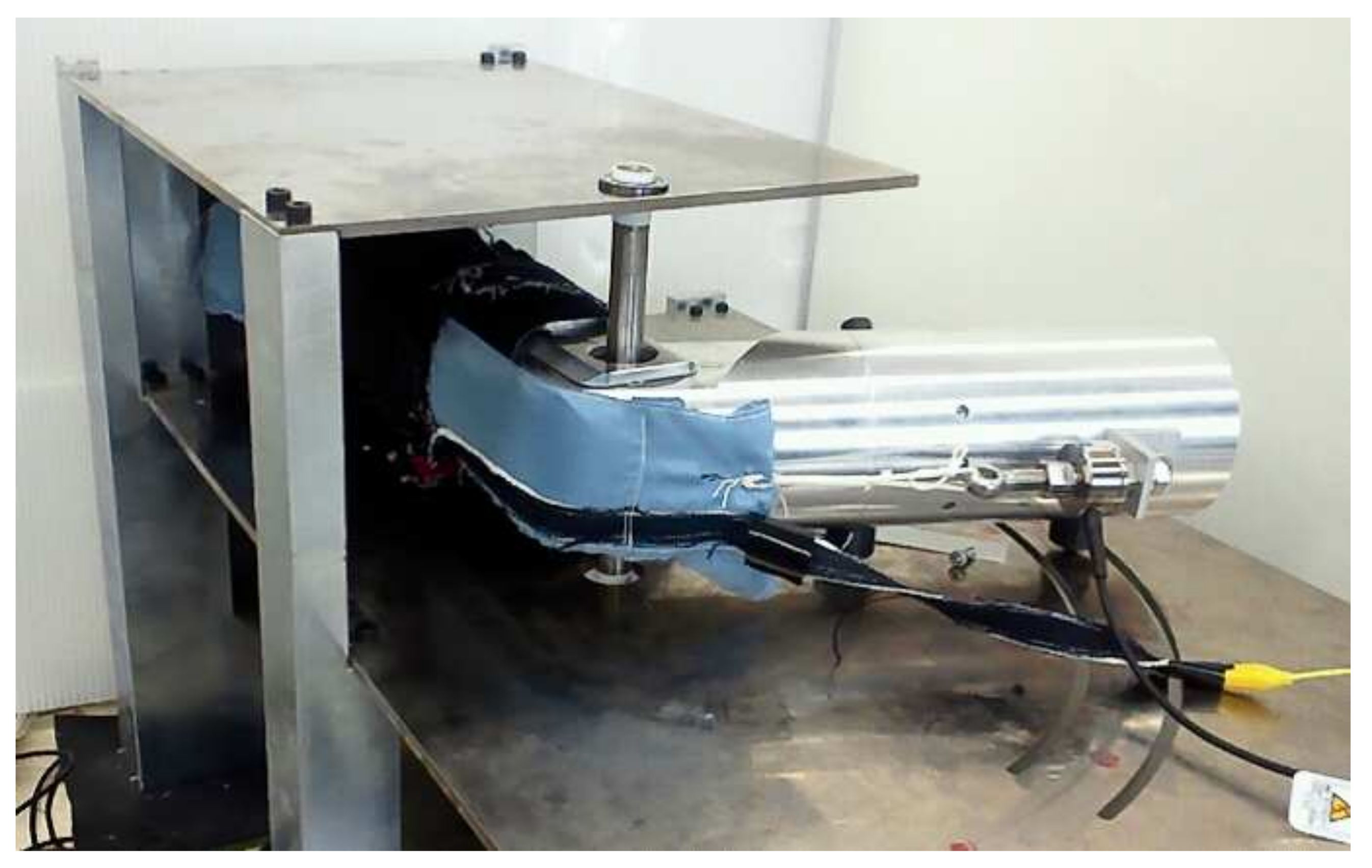
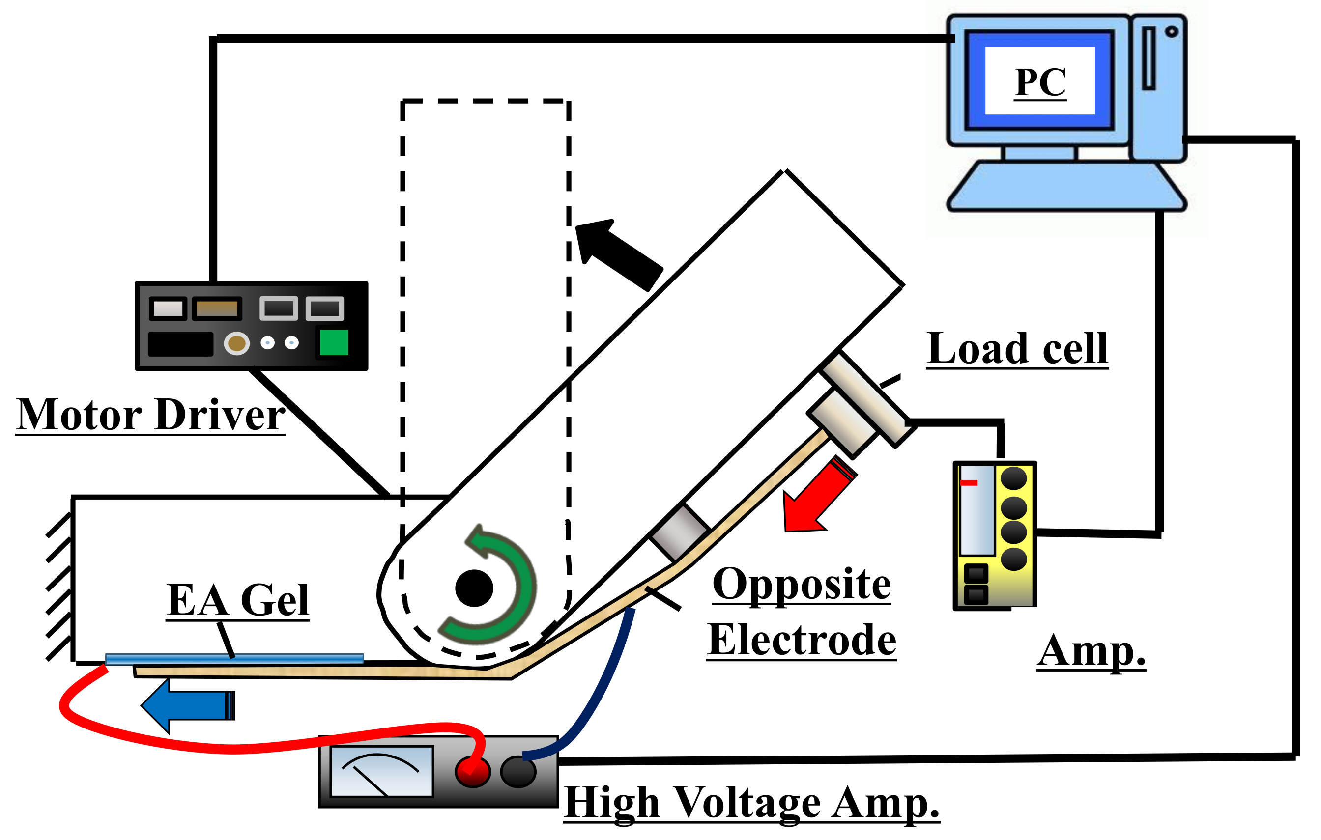
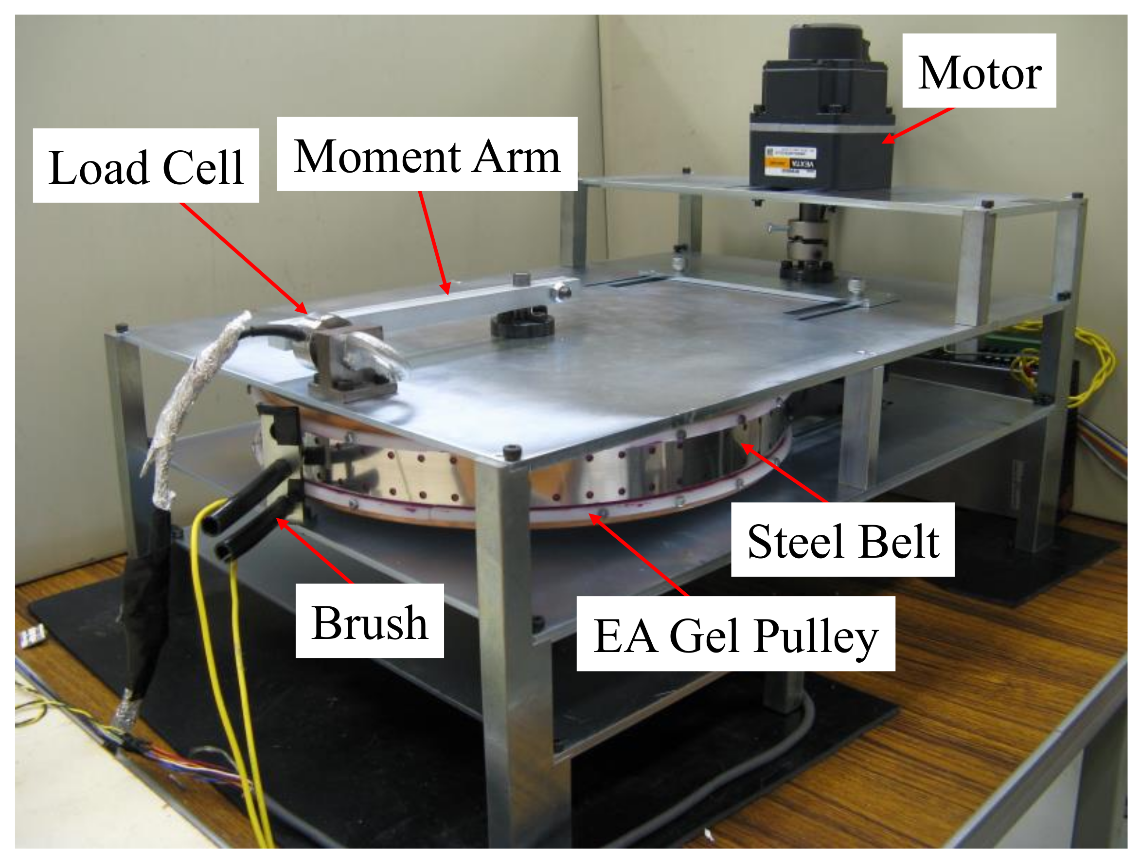
Figure 9 is a photograph of the experimental setup, and
Figure 10 is a diagram of the principle [
15]. An electrode sheet and an EA gel sheet were attached in this order to the side of a cylinder with a radius of 40 mm, which was fixed to the wall. The fore-cylinder was connected to the motor at the joint and was driven by commands from the PC. The counter-electrode sheet, which was connected to a load cell fixed to the fore-cylinder, was lightly pressed and fixed with a cuff to the EA gel on the wall-side cylinder. As the fore-cylinder rotated, the counter electrode slid on the EA gel in the direction of the cylinder axis, and the braking force generated between the counter electrode and the EA gel was measured by the load cell. The EA gel was modified to have a tougher surface, and the shear stress was assumed to be slightly lower than in the previous section, approximately 5–8 kPa.
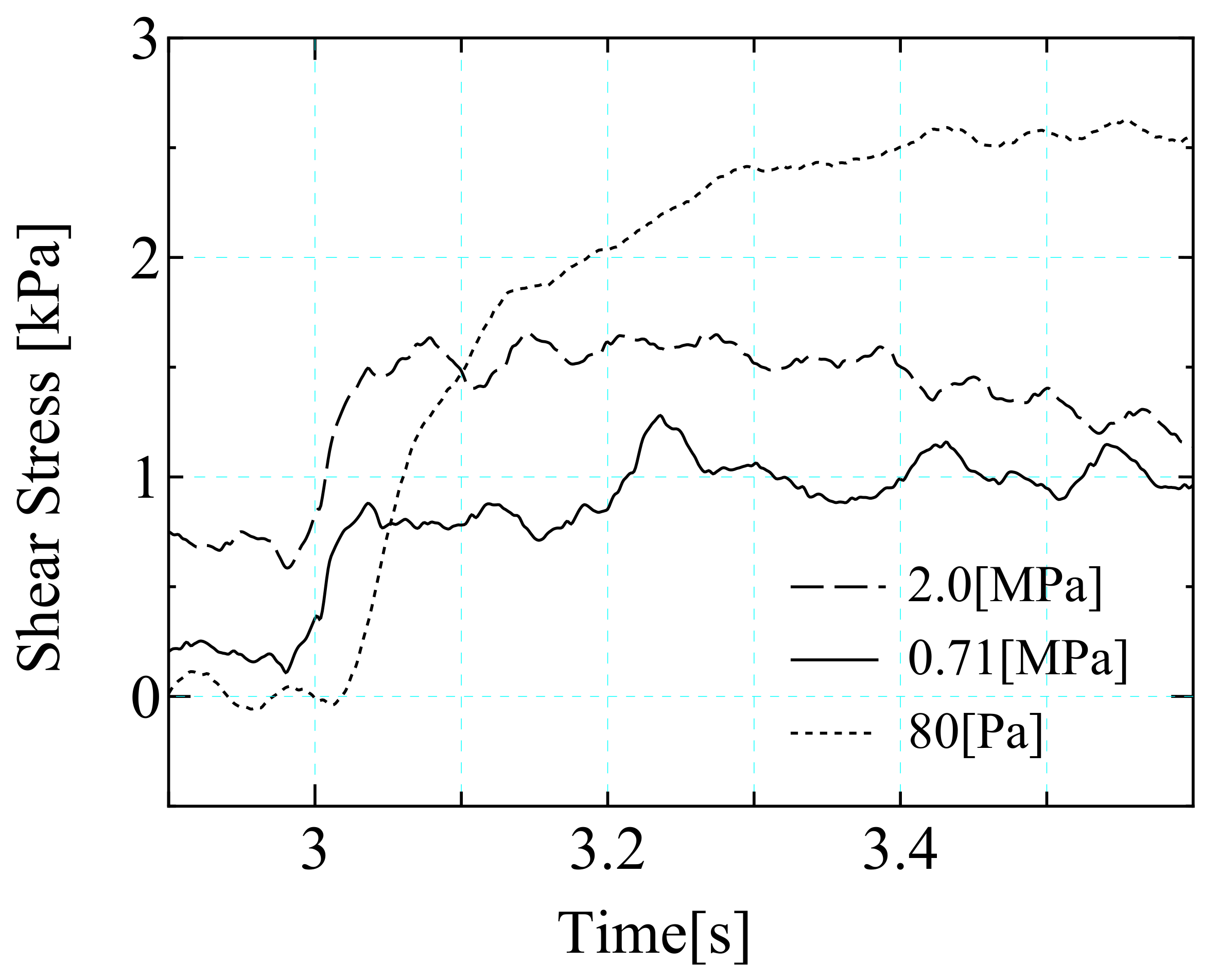
Figure 11 shows the experimental results. Note that the shear stress measured by the load cell was higher than the original shear stress because the force measured by the load cell included the partial force that pulled the electrode sheet towards the axis of rotation. The shear stress increased with the strength of the electric field, but the increment was small and the value was large even with no electric field.
The smaller-than-expected change in shear stress indicates that the contact between the counter electrode and the EA gel was insufficient. However, the larger value in the absence of an electric field indicates that the surface pressure was excessive in the area where the counter electrode and EA gel were in contact. Although we were unable to measure the surface pressure quantitatively, changing the cuff pressure did not achieve a higher shear stress than in the experiment.
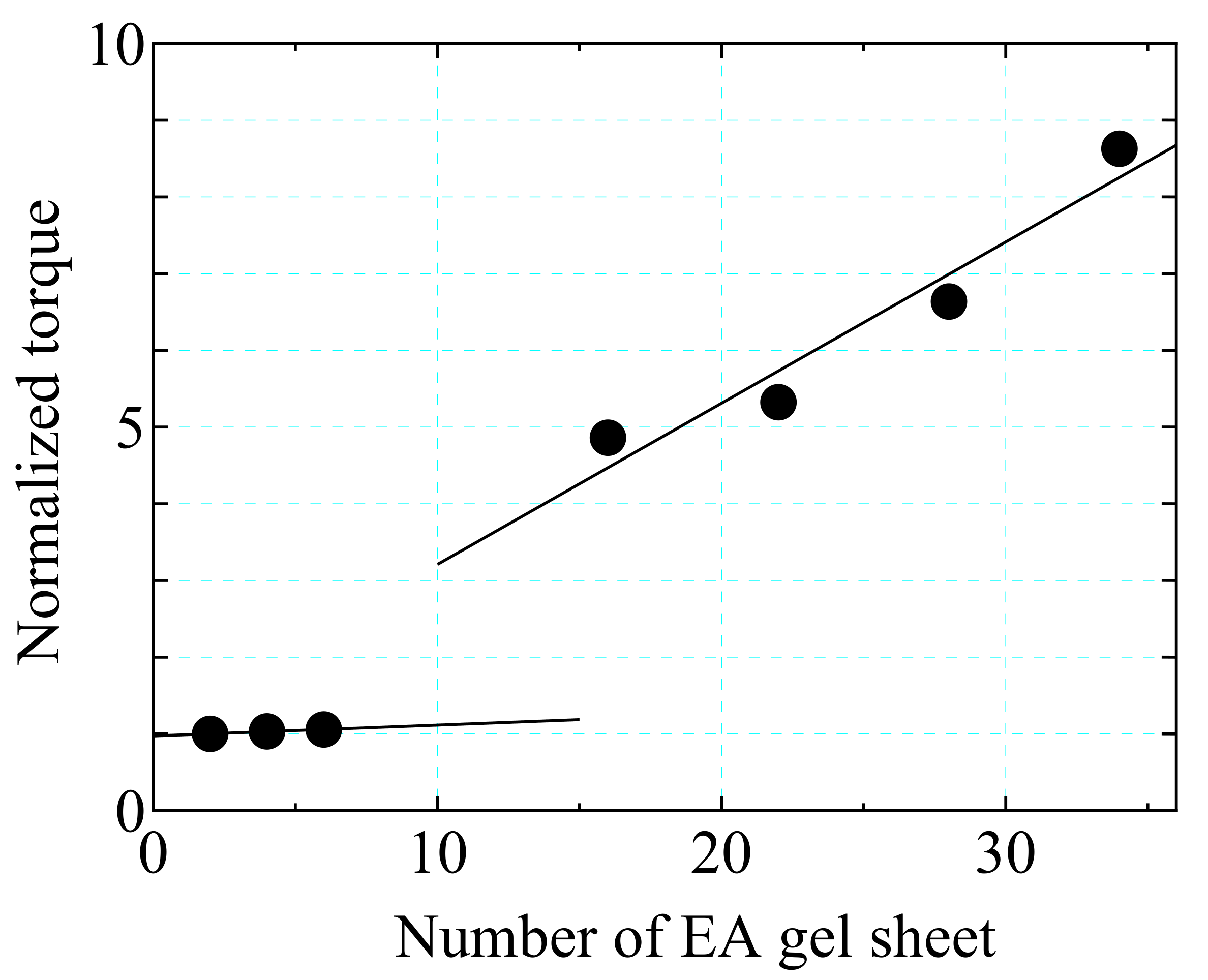
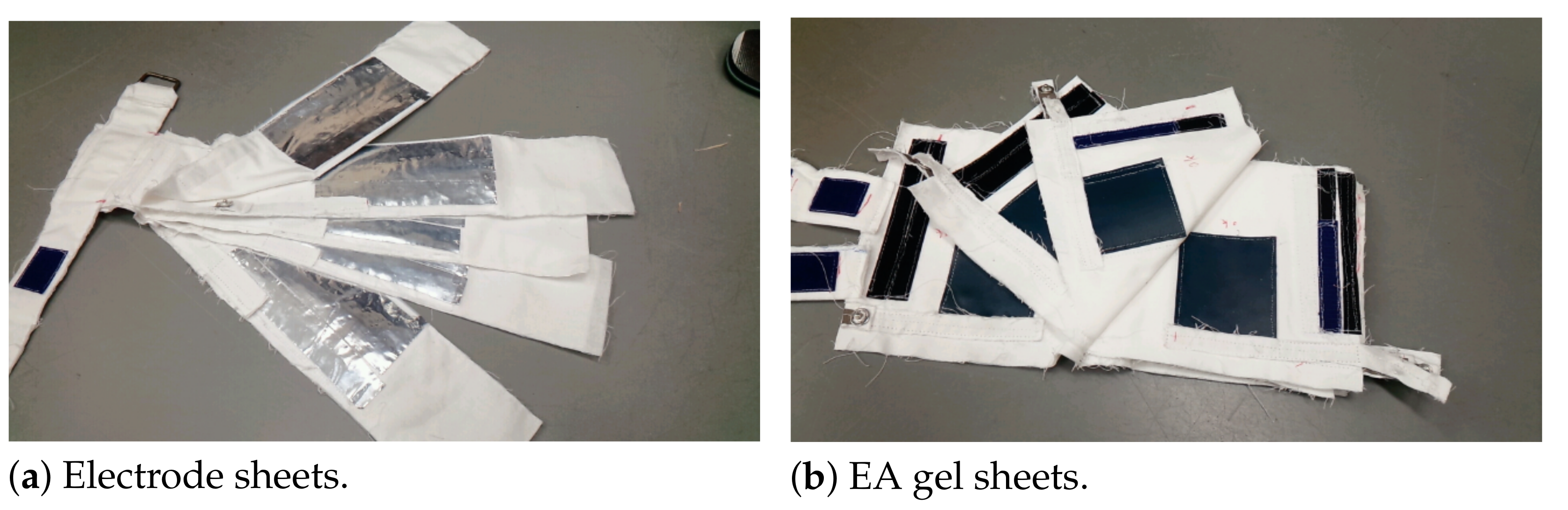
On the basis of the results above and in the previous section, a new multi-layered EA gel and electrode sheets were developed to improve the shear stress and increase the braking force by stabilizing the surface pressure. As shown in
Figure 12, the electrode sheets (a) and EA gel sheets (b) were alternately stacked, and the number of EA gel sheets was increased from 1 to 10. The results are shown in
Figure 13. As the number of EA gel sheets increased to seven, the shear stress increased with no electric field, but decreased under an applied electric field. However, when 10 sheets were used, both the shear stress without an electric field and the enhanced shear stress with an applied electric field decreased. The 10-sheet layered EA gel was thicker, making it more difficult to roll with the cuff. However, if the cuff was rolled more tightly, the initial surface pressure on the EA gel was considered to be excessive. The cuff was rolled weakly with this in mind, but it might have been too soft, resulting in insufficient contact.
These results indicate the following: When there is shearing along the axis of the cylinder, it is necessary to deform the electrode or EA gel in the circumferential direction using a jig such as the cuff used in this study and to apply a constant surface pressure to the EA gel. However, if a material with sufficient stiffness in the shear direction is used for the electrode, it cannot be deformed sufficiently to follow the cylindrical surface unless it is squeezed strongly. This makes it difficult to achieve the desired constant surface pressure on the EA gel and generate the expected stable shear stress. It is therefore necessary to consider the design to install the EA gel and electrode sheets in such a way as to solve these problems. Alternatively, the installation along the circumference becomes relatively easy if the mechanical structure in the circumferential direction is long enough compared with the curvature. This easily averages the surface pressure on the EA gel. Thus, it may be possible to generate shear stresses similar to those used on a flat surface.
5. EA Gel Is Curved in the Shear Direction
This section corresponds to
Figure 4c.
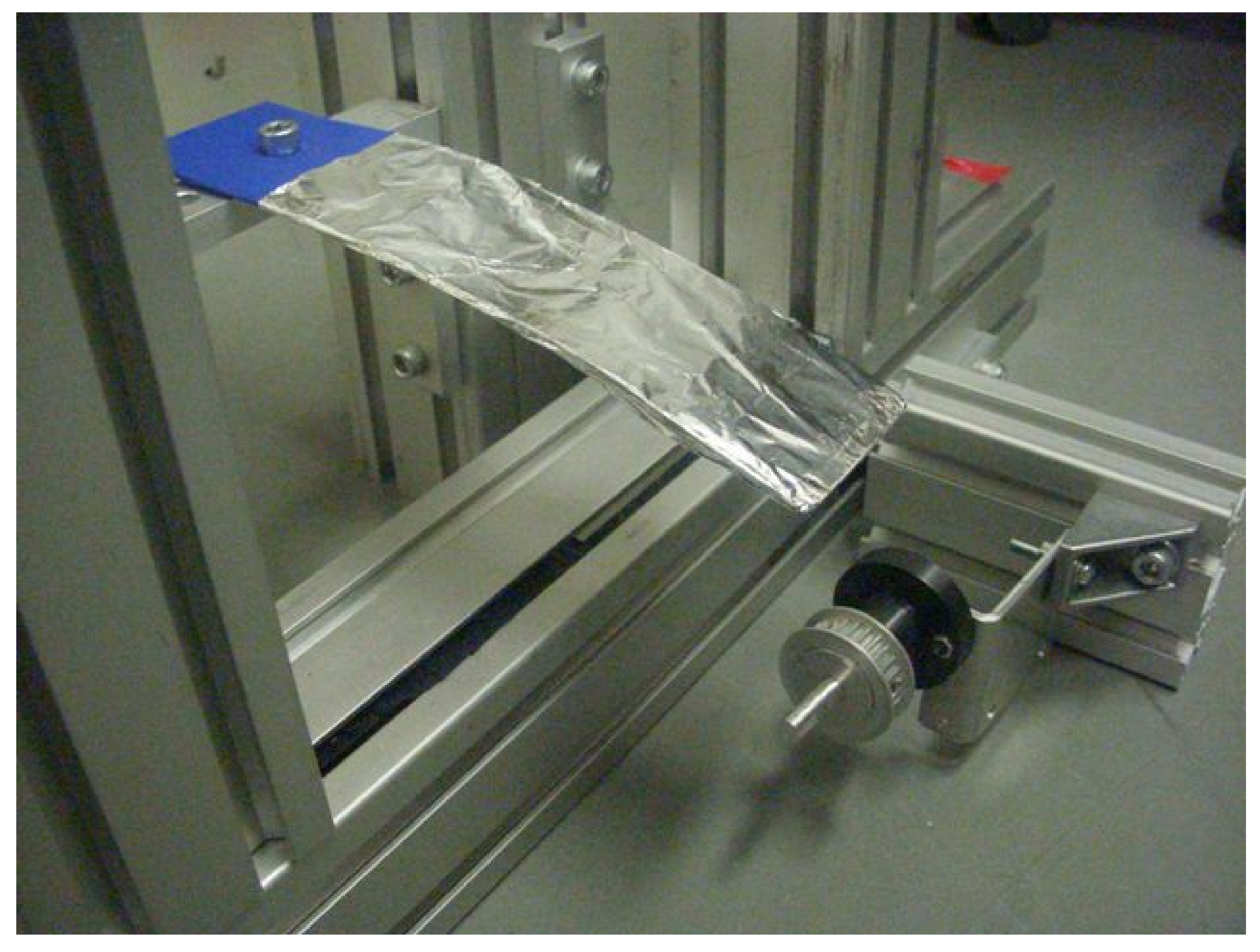
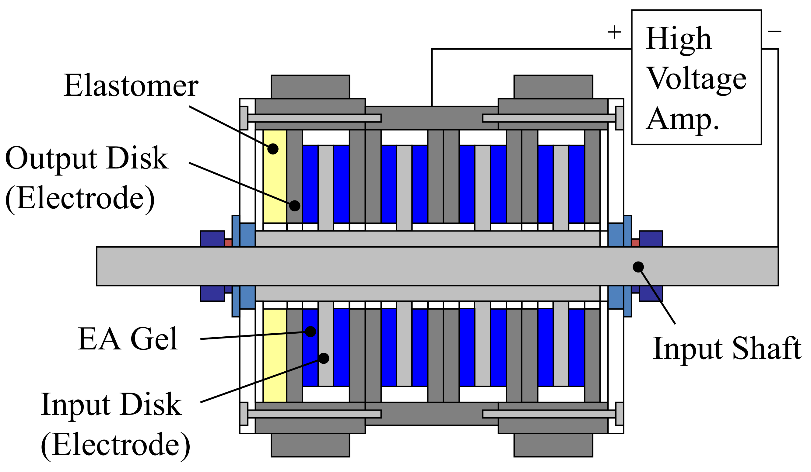
Figure 14 is a photograph of the experimental apparatus, and
Figure 15 is its principle diagram [
12]. The apparatus was a flat-belt-drive system in which the transmission torque can be controlled using an electric field applied to the EA gel. A motor was connected to the driving pulley, and the electrode sheet and the EA gel were attached to the side of the driven pulley, which had a radius of 150 mm. The flat belt was made of steel and served as a counter electrode. The contact pressure between the belt and the pulley was generally not constant on the driven pulley, but was highest around the opposite side of the driving pulley. For this reason, the initial tension of the belt was kept quite low in this apparatus, while the slippage between the belt and the driving pulley was reduced by idlers and sprockets. The EA gel used in this apparatus had properties intermediate between those in
Section 3 and
Section 4.
The transmitted torque
T was measured with a load cell pushed by an arm fixed to the driven shaft. The relation between the transmitted torque and the shear stress is
where
is the shear stress of the EA gel,
h is the width,
r is the radius of the driven pulley, and
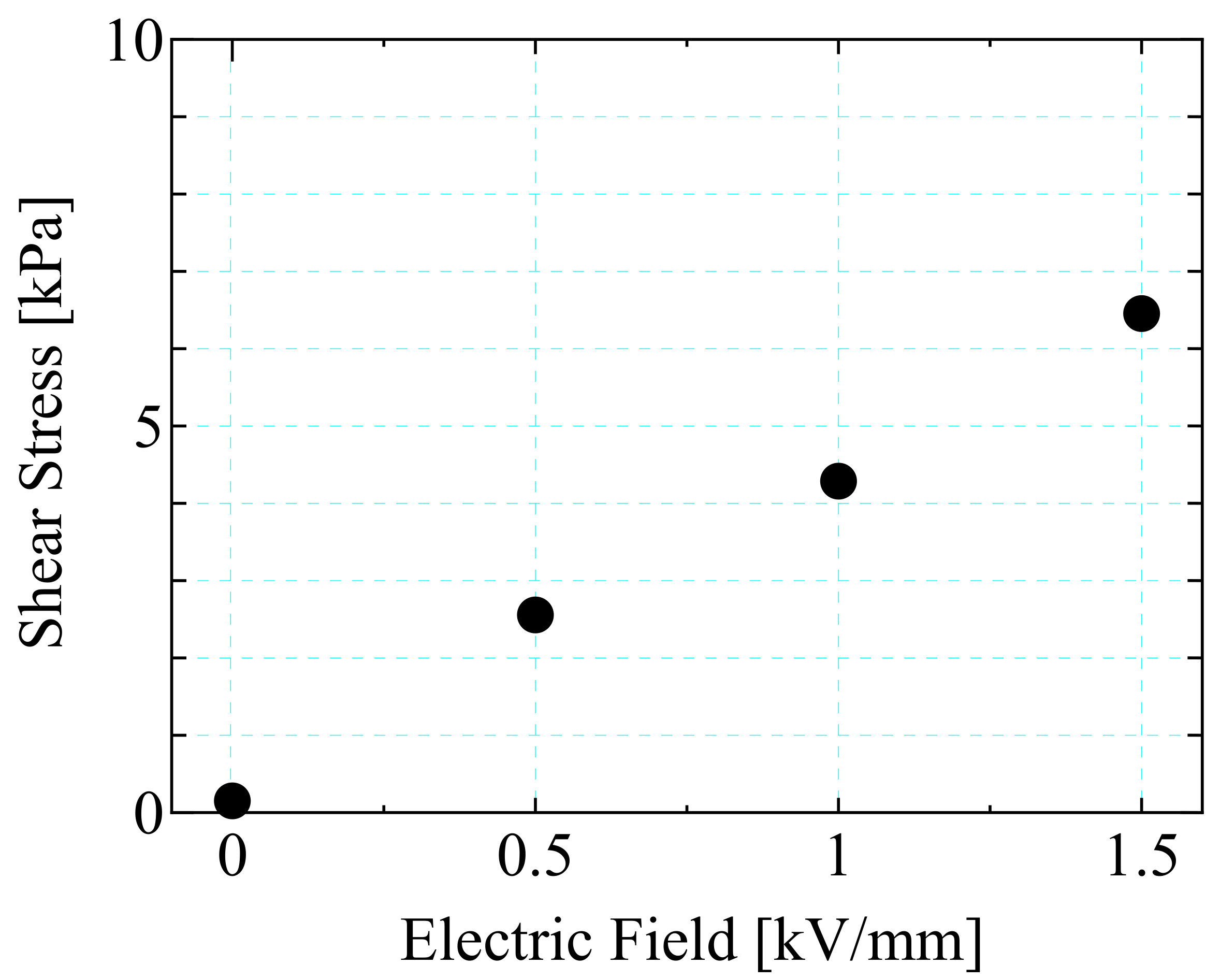
is the winding angle at the driven pulley. The relationship between the electric field and the shear stress determined from the step response experiment is shown in
Figure 16 [
12]. The shear stress was about 5 kPa at 1 kV/mm, which was approximately what was expected.
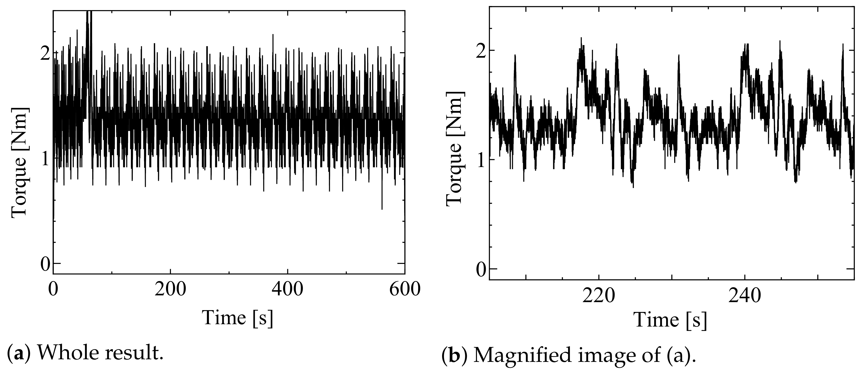
In a new experiment, the torque was measured for 10 min while an electric field of 0.5 kVmm was applied. The results are shown in
Figure 17a. The torque showed oscillations with an amplitude up to 0.5 Nm, which appeared to be a combination of several modes. A magnified image is shown in
Figure 17b. The vibrations with the shortest period were electrical vibrations and mechanical vibrations of the sensor, the belt, and the mechanical structure. The longest oscillations had a period of 225–247 s, which corresponds to the period of the belt’s revolution. The longest-period oscillation had the highest torque variation. This is because the joint of the steel belt passes through characteristic points such as the idler and the beginning of the winding with each pulley [
11]. In other words, the surface pressure on the EA gel around such points was reduced because a part of the steel belt around the joint was warped in the lift-off direction of the EA gel, which reduced the shear stress, especially on the slack side of the belt. As the joint moved towards the tight side of the belt, the contact was restored and the shear stress increased owing to the increased pressure of contact of the belt with the EA gel pulley. Vibrations corresponding to the belt rotation period were generated by repeating this process.
The above confirms that the contact between the EA gel and the counter electrode and the magnitude of the pressure acting on the gel surface had a significant effect on the shear stress generated by the gel. However, compared with
Figure 4b, the structure of
Figure 4c has a sufficiently long EA gel circumference in relation to the curvature, so that even a rigid counter electrode such as a steel belt was easily installed along the circumference without strong pressure. Therefore, the surface pressure on the EA gel was approximately appropriate. The shear stress with no applied electric field was low, while the increase when an electric field was applied was large, but the shear stress was sometimes oscillatory when the counter electrode was not smooth because the surface pressure varied across the EA gel.
6. Variation in Properties with Different Curvatures
In this section, we take the situation in
Figure 4c a step further and consider a state where both curvature and surface pressure varied.
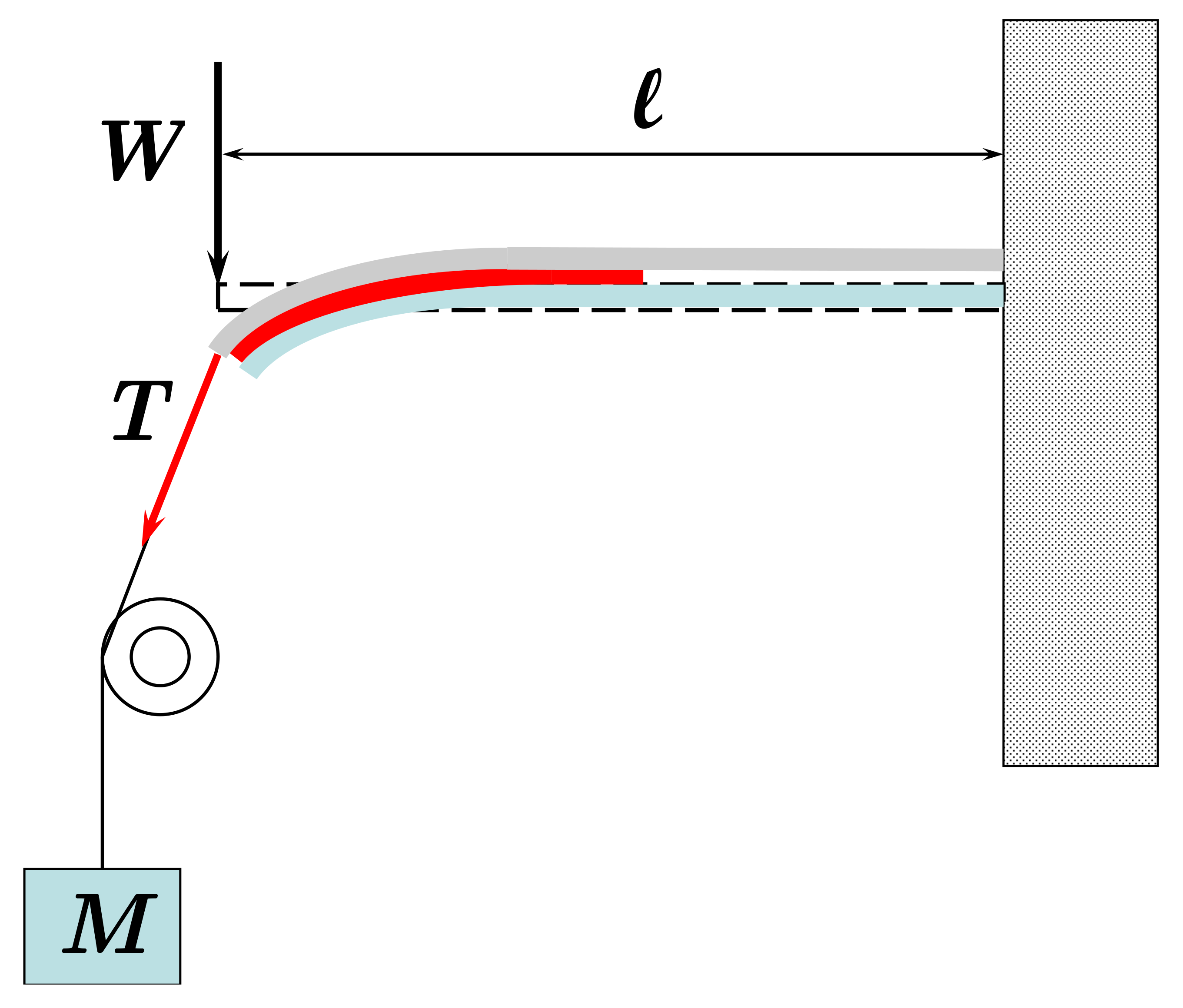
The experimental setup is shown in
Figure 18, and the schematic is shown in
Figure 19. The EA gel sheet was sandwiched between an upper plate (made of rubber) and a lower plate (made of polypropylene resin). Each plate was wrapped with aluminum foil to form an electrode. A string was fixed to the top of the upper plate, and a weight was attached to the end of the string. When the weight was released, the upper and lower plates bent and slid in the shear direction. However, when the weight was released after applying an electric field to the EA gel, the plates came to rest at a position where the braking force of the gel,
F (N), the elastic force of the plate, and the string tension of the weight were balanced.
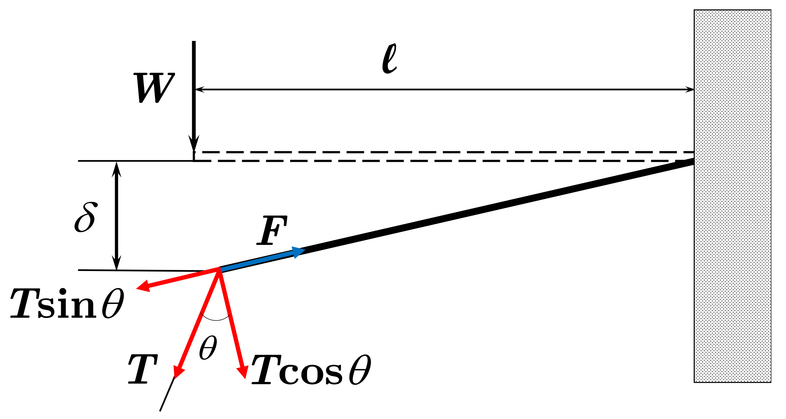
The shear stress at the surface of the EA gel can be calculated as follows. First, the upper and lower plates and the EA gel were considered as a single beam. We also assumed that the slope was constant and the shear stress on the EA gel was uniform on the plates. The experimental conditions in this case can be approximated as in
Figure 20. The load
W (N) acting on the tip of the plate is the normal component of the string tension
T (N); thus,
from the figure. Assuming that the upper plate was made of sufficiently soft rubber, the Young modulus of the lower plate was
N/mm
2, the area moment of inertia was
mm
4, and the length of the plate was
mm. While the deflection
(mm) was not small, for simplicity, it was approximated using the following general formula for deflection:
The angle
between
T and
W can thus be written as
Here, the braking force due to the EA gel and the component of
T parallel to the plate are equal in the direction parallel to the plate surface. Therefore, when the contact area between the EA gel and the upper plate is
mm
2, the shear stress
(Pa) can be obtained from Equation (
3) as
The deflection was measured during the experiment. Because the maximum static frictional force on the EA gel surface had to be determined, the weight was increased after the electric field was applied until the EA gel and the plate were too far apart to maintain equilibrium. The same EA gel was used as in the previous section.
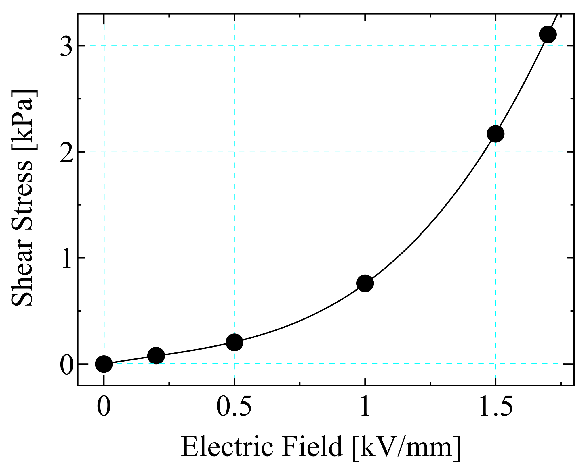
The experimental results are shown in
Table 1 and
Figure 21. In the table,
is the curvature, which was geometrically determined from
. The curve in the figure was approximated as a cubic function passing through the origin (
) with a correlation coefficient of 0.99. The figure shows that the shear stress increased with the applied electric field and that the magnitude of the shear stress was similar to that in
Figure 11, but the increase is much larger in
Figure 16. In addition, the change in shear stress was much steeper at higher electric fields than in
Section 4 and
Section 5. The surface pressure in this experiment calculated from
was approximately 0.13–0.16 kPa. Although the pressure increased together with
T, it was lower than the surface pressure of about 0.5 kPa given in
Section 3. This means although the surface pressure was stable, it was too low. Therefore, the adsorption was insufficient at low electric fields, but was sufficient at high electric fields to produce a high shear stress.
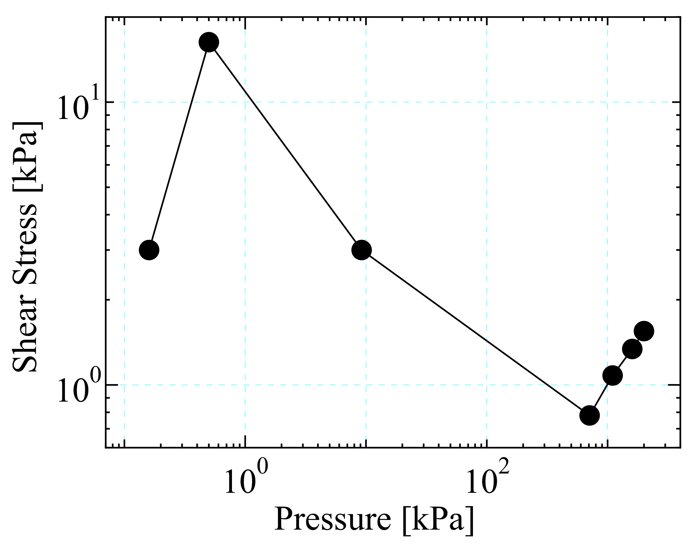
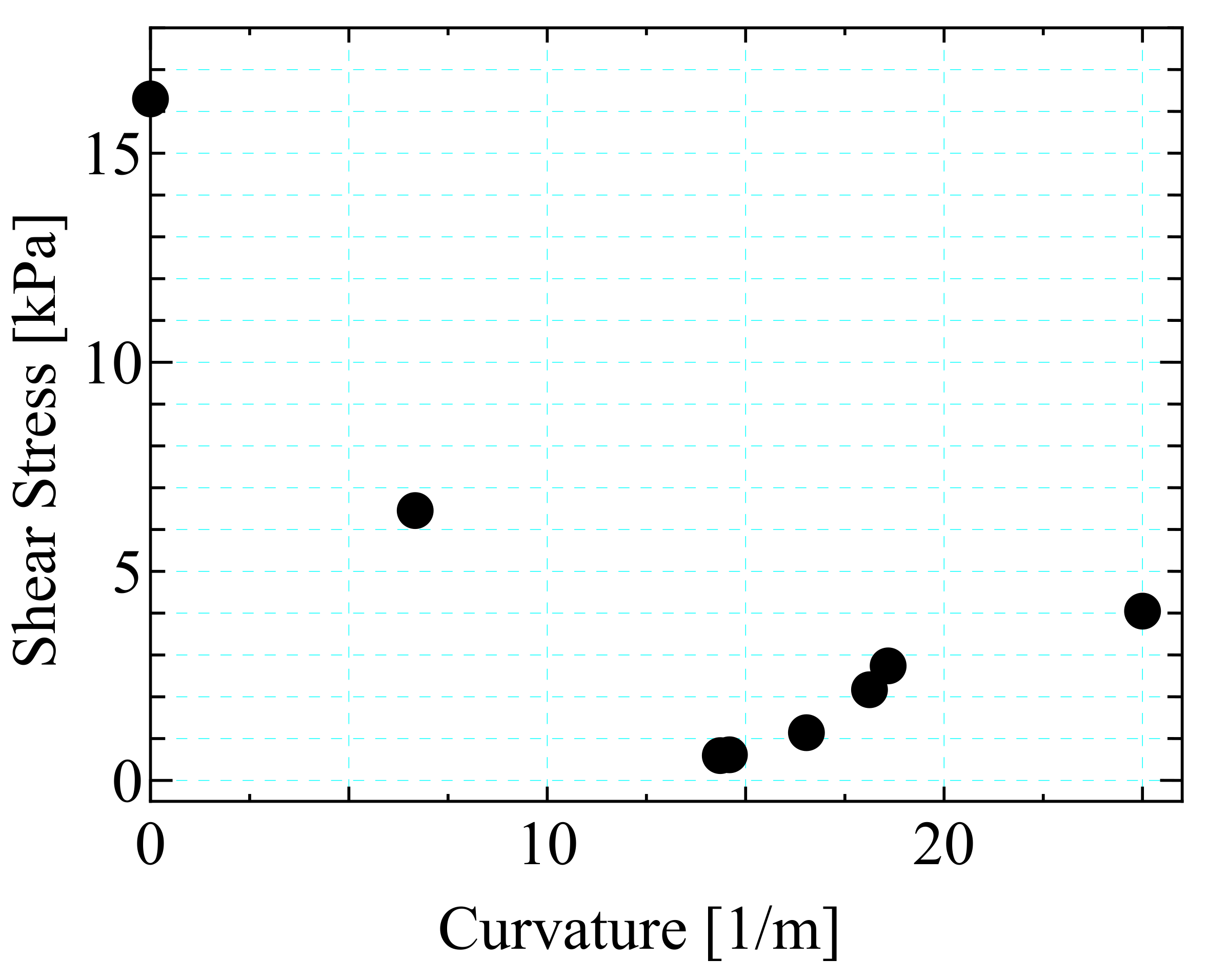
Figure 22 summarizes the experimental results for curvature and shear stress. The shear stresses in
Section 3,
Section 4 and
Section 5 are shown for an applied electric field of 1.5 kV/mm. For
Section 6, the shear stresses in the respective electric fields were taken to be equivalent to 1.5 kV/mm using
Figure 16. The figure shows that the shear stress decreased with increasing curvature from the plane and gradually increased from approximately 14
. This means that as the curvature increased, the shear stress decreased owing to the inability to provide a suitable constant surface pressure. However, a strong electric field was applied when the curvature was even greater, which stabilized the adsorption state and increased the shear stress, especially in
Section 6. This result means keeping an appropriate EA gel surface pressure is more important than the curvature itself. From this viewpoint, the relationship between the pressure on the EA gel surface and the shear stress in the paper is shown in
Figure 23 as a double logarithmic graph. The best point was at approximately 0.5 kPa. The shear stress increased for higher surface pressure, but the shear stress also increased without an electric field, so the effective shear stress was not high.
7. Conclusions
This paper summarized research results on transmission/braking elements with EA gel on a curved surface, with a focus on the initial pressure on the EA gel surface.
In
Section 3, the EA gel was applied to a flat surface and a surface pressure of about 0.5 kPa was applied, which resulted in a high shear stress. This indicated that the surface pressure was appropriate. In
Section 4 and
Section 5, the surface pressure was not shown because of the difficulty in determining it, but it could be estimated to some extent from the shear stress. That is, the EA gel in
Section 4 was curved so as to be orthogonal to the shear direction, but the surface pressure was too high. The EA gel in
Section 5 was bent in the shear direction, but the surface pressure was in an appropriate range. In
Section 6, the EA gel was curved in the shear direction and the curvature was varied, but the surface pressure was around 0.15 kPa, which was too low. The results of this paper showed that the surface pressure on the EA gel should be about 0.5–1 kPa.
This study found that even an EA gel attached to a curved surface can be used as a stable and controllable transmission/braking element if the structure provides a stable surface pressure of about 1 kPa to the EA gel surface.
However, while tensile or compressive stress is generated on the surface by the curvature of the EA gel, this was not taken into account in this paper. In all the experiments in this paper, the EA gel was curved so that the counter-electrode side was convex; thus, tensile stress was generated on the surface. This caused the particles on the surface to be rougher and the electrical flux lines between the electrodes to be more dispersed than on a flat surface. The particles were less constrained by the gel component, making it easier for them to drop out and to move inside the gel component at the same time. Therefore, the response of the shear stress to the electric field became faster and stronger because the counter electrode was in better contact with the gel component than when it was flat. The shear stress also increased even under no electric field. The opposite phenomenon is expected to occur when the counter-electrode side is concavely curved. We have not confirmed these phenomena in this paper, but it will be necessary to discuss whether the counter electrode should be placed inside or outside the curved surface.


