Abstract
In this paper, a fault diagnosis method of a heterogeneous multi-agent is proposed that realizes the rapid and accurate fault diagnosis of a redundant multi-type actuation system of large aircraft. Firstly, the multi-agent model of a large aircraft actuation system is established, the composition of the actuation system and the relationship between each multi-agent are clarified and three different types of actuator mathematical models are established. Secondly, a fault detection and isolation (FDI) model is established and transformed into an optimization problem according to different performance index requirements. Aiming at the optimization problem, combined with the principle of linear matrix inequality (LMI), the fault diagnosis algorithm of a heterogeneous multi-agent system is designed. Moreover, the threshold judgment method based on the error signal is presented. Finally, the three actuator models of the aileron actuation system of large aircraft are combined to complete the fault diagnosis of a heterogeneous multi-agent system under the given model interference and model fault. The obtained results demonstrate and validate that the proposed method can accurately and effectively diagnose the faults of the actuator and its associated actuators.
1. Introduction
The actuation system is one of the most important parts of the flight control system of the aircraft, which is vital to flight safety. With the development of more electric aircraft/all electric aircraft in recent decades, the actuation systems of the aircraft have correspondingly moved from hydraulic actuation systems to hybrid actuation systems to power-by-wire (PBW) actuation systems. For the hydraulic actuation system, the control surfaces are driven by electro-hydraulic actuators and the power is supplied in a centralized manner with complex pipelines, which leads to the potential leakage and contamination of oil, and a low reliability, maintainability and combat survivability. In contrast, the actuation power is electrically distributed in the PBW actuation system. Without a heavy hydraulic infrastructure, the PBW actuation system has the characteristics of a lower weight, less maintenance and production costs and dissimilar redundancy [1]. However, the application of the PBW actuator is limited only to secondary flight control surfaces due to the immaturity of the PBW actuation systems. Therefore, comprehensive research on fault diagnosis of the PBW actuation system is essential to tackle the problems of slow responses and poor thermal dissipation, ensure the system’s reliability and extend its application field.
The common fault diagnostic approaches are mainly divided into two categories, namely model-based [2] and data-driven [3]. A few studies have been conducted on the fault diagnosis of the actuator. Ma et al. proposed a nonlinear unknown input observer (NUIO)-based fault diagnosis method for an intelligent hydraulic pump system [4]. Considering the real-time requirements and the special structure of the pump, the NUIO diagnostic method could accurately diagnose and isolate the two typical failure modes. Xu et al. developed a model-based fault detection and isolation (FDI) scheme for a rudder servo system [5]. NUIOs were designed to eliminate the influences of unknown disturbances and the scheme was validated on an actual test rig. Doraiswami R. et al. introduced the linear parameter-varying (LPV) approach to model the physical system considering both system dynamics variations and emulator parameter variations [6] and applied a Kalman filter to detect and isolate faults of the position control system. Balaban et al. adopted a hybrid diagnosis approach combining model-based and data-driven methods to monitor and diagnose several fault types common to an electro-mechanical actuator (EMA) [7]. An observer was used to detect the fault and a diagnose tree was identified to isolate the fault. Mazzoleni et al. [8] collected the mechanical defects fault data from an EMA and modified the standard particle filter to face the fault detection issue on the EMA. Based on the Dempster–Shafer (D–S) evidence theory. Lu et al. presented a multi-source information fusion fault diagnosis approach for the aviation hydraulic pump by utilizing the three-level signals from the pump level, hydraulic power system level and hydraulic actuation system level [9]. The multi-source approach can not only significantly increase the belief level supporting the diagnosis target but can also diagnose a fault correctly even if a sensor is faulty. Ramos et al. proposed a new classification scheme using fuzzy clustering techniques [10] and validated it on the DAMADICS benchmark [11]. Lu et al. applied a two-step radial basis function (RBF) neural network to implement the fault detection of a multiple redundancy aileron actuator and used a system observer and a force motor current observer to realize the fault diagnosis [12]. Sharifi et al. [13] adopted the representation learning approach to detect the internal leakage in the electro-hydraulic system and developed a custom-built optimization algorithm to map the raw data, making the classification easier. The above-mentioned studies mostly used the model-based methods, which rely on the residual generation between the real outputs and the outputs of the system model. However, the exact system model is not a necessity for the data-driven methods, but plenty of fault data are required.
While a significant amount of literature is available on the fault diagnosis of the single actuator, the issue of fault diagnosis for the aileron actuation system has been rarely addressed. Nahid-Mobarakeh et al. [14] employed a multi-agent system for the fault diagnosis of the aileron actuation system. In their approach, an FDI agent was considered for each aileron and the agent received information from its EMA and its neighbors, which improved the reliability of the fault detection. The authors applied the partially decentralized FDI strategy and the multi-agent system, which accords with the current distributed control trend for the actuation system. However, each aileron was driven by two similar EMAs and only the primary and stand-by operating modes were considered. To meet the requirements of practical applications, it is necessary to also study other types of actuators, such as the electro-hydraulic servo actuator (EHSA) and electro-hydrostatic actuator (EHA).
A multi-agent system (MAS) has gained significant interest in many areas due to its distributed structure, such as unmanned aerial vehicles [15], power grids [16] and multiple robotic systems [17]. The research interests of MASs mainly focus on formation control and the consensus problem. The easy spread of the fault from one agent to other agents and the increasing complexity of the system make it rather important to study the fault diagnosis of MASs. Various studies have proposed FDI filters [18,19,20,21,22]. However, the research objectives in these studies were restricted to homogeneous agents whose applications are limited. The hybrid and PBW actuation systems consist of different types of actuators. Thus, homogeneous dynamics are no longer applicable. Li et al. proposed a distributed FDI strategy for a heterogeneous MAS using only relative information [23]. However, the effects of disturbances on the residual were ignored. In practice, disturbance always exists, which might result in mistakes in diagnosis. Davoodi et al. [22] and Chadli [24] designed a distributed FDI filter for heterogeneous MASs by solving the multi-objective optimization problem. However, the filter was required to construct at each agent. Quan et al. designed a full-order observer at the special agent with local information to realize fault diagnosis for heterogeneous discrete-time MASs, whereas the MAS in the paper was composed of first- and second-order agents [25]. It is easy to see that the order of the actuator model in practice is not suitable for this prerequisite. To the best of the authors’ knowledge, there is scarcely an open report on the fault diagnosis of actuation system based on MASs [26,27,28,29]. Therefore, it also remains challenging to apply the MAS-based method on the FDI for the actuation system.
In this paper, a heterogeneous multi-agent-based fault diagnosis scheme is proposed for the actuation system. The main contributions are summarized as follows. The state and output estimator are designed and based on the performance index requirements, and the optimization problem is transformed into a linear matrix inequality (LMI) problem. Finally, the fault diagnosis of the heterogeneous multi-agent system is realized.
The remainder of the paper is organized as follows. Section 2 describes and proposes the mathematical model of the problem. In Section 3, different actuator models are established. Heterogeneous multi-agent-based fault diagnosis is presented in Section 4. The simulations are presented in Section 5 and conclusions are provided in Section 6.
2. Problem Description
Although the PBW actuation system has a variety of advantages, it has not yet seen widespread applications in aircraft and is only applied on the F-35. Instead, the hybrid actuation systems have been in several types of aircraft for the transition to more electric aircraft. The electro-hydraulic servo actuator is the most commonly used actuator of hydraulic actuation systems. The electro-mechanical actuator and the electro-hydrostatic actuator are the two typical actuators of PBW actuation systems. The hybrid actuation system consists of PBW actuators and traditional EHSAs. It provides an opportunity to introduce the potential benefits of the PBW actuation system to flight control.
The fault diagnosis for the actuator can only detect and isolate the faults in a single actuator, whereas the diagnosis for the system can deal with all of the actuators in the system. However, the fault diagnosis for the actuation system is still in its infancy. To design the fault diagnosis scheme for the multi-agent actuation system, the construction of the multi-agent network for the actuation system must be solved primarily.
The distributed control of the actuation system has become a tendency, which enhances the self-control and self-management abilities of the system. The distributed control architecture relies on the actuator itself rather than the flight control computer to achieve deflection and fault diagnosis. Therefore, an optimal actuator topology should be determined considering practicability. That is, the mapping relationship between the actual actuation system and the multi-agent system will be established with communication constraints among actuators.
With the actuator network decided, the fault diagnosis problem of the actuation system is then transformed into the fault diagnosis problem of the multi-agent system. For the selected agent, the faults that occurred in the given agent, as well as in other agents, should be detected and isolated.
2.1. Multi-Agent Architecture
Figure 1 shows the aileron system of a large aircraft. The system has three ailerons, and each aileron is driven by two actuators.
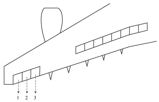
Figure 1.
Primary flight control surfaces layout.
In the aileron system, an agent is considered for each aileron and the agent can detect not only its fault but also the fault of adjacent agents. The topology of the multi-agent system is shown in Figure 2.

Figure 2.
Topology structure of the multi-agent system.
2.2. Multi-Agent Model
Considering heterogeneous and stable multi-agents, the dynamic model of multi-agents can be expressed as:
where is the state, is the interference and noise (external environmental factors), is the fault signal, is the control input, is the output of agent I and . are the relative constant matrices. and are the fault metrics related to selectable and isolatable fault signals, respectively, and , .
Each agent is also equipped with sensors for relative output measurement, and and represent the sets of agents that agent i can perceive and the designated neighbors of agent i, respectively. Since each agent is equipped with relative output measurement, it is assumed that all agents have the same number of outputs. Therefore, according to the information interaction between the agents and the dynamic models of different orders, this paper will diagnose the fault of agents in the multi-agent system using the measurement output and the outputs of adjacent agents.
Since the dynamic models of different actuator models are different, the above heterogeneous multi-agent system can be utilized to describe the redundant actuation system.
The definition represents all of the information, including other agents, that agent i can obtain. depends on the output of the ith agent and the output of adjacent agents, and .
According to the above definition, the virtual model of the ith multi-agent is as follows:
where , , , , .
It can be seen from the above virtual model that there is information interaction between the agents. Thus, the core of heterogeneous multi-agent fault diagnosis is to diagnose the fault signal of a given agent or other adjacent agents according to the obtained information.
3. Actuator Model
Figure 3a–c shows the schematics diagrams of the electro-hydraulic servo actuator (ESHA), electro-hydrostatic actuator (EHA) and EMA, respectively. In this section, the mathematical models of these three types of actuators are established.
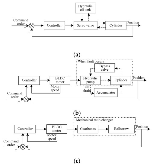
Figure 3.
Schematic diagrams of three types of actuators. (a) EHSA; (b) EHA; (c) EMA.
3.1. Electro-Hydraulic Servo Actuator Model
As shown in Figure 3a, the electro-hydraulic servo actuator mainly consists of the electric controller, a servo valve and a cylinder. The spool displacement of the servo valve is controlled according to the signal generated by the controller. Then, the pressure and the flow between the chambers are changed and, finally, the piston in the cylinder drives the surface.
The spool dynamics are modeled as a second-order system considering that the bandwidth of the servo valve is larger than the eigenfrequency of the fluids:
where is the spool displacement; is the opening/current gain of the servo valve; denotes the input current; and are the damping coefficient and the natural frequency of the servo valve, respectively.
The flow through the servo valve can be expressed as:
where denotes the flow/opening gain at a null pressure drop of the servo valve; is the servo valve flow/pressure gain and represents the load pressure of the servo valve.
Neglecting the internal leakage effects, the flow dynamics in the chambers is described as:
where is the piston area; denotes the displacement of the cylinder; is the total volume of the chambers; represents the effective bulk modulus of the fluids; and is the external leakage coefficient of the cylinder.
The piston movement is described using the force equilibrium equation:
where is the lumped piston mass; denotes viscous resistance in the cylinder; and is the output force.
3.2. Electro-Hydrostatic Actuator Model
Compared with the traditional EHSA, the EHA eliminates the need for an external hydraulic power supply. Instead, the accumulator is used as the hydraulic oil tank. A brushless direct current (BLDC) motor drives a hydraulic pump to circulate high-pressure fluid into the piston chamber. When a fault occurs, the system is protected by the bypass valve.
The mathematical model of the motor can be expressed as:
where is the input voltage; is the back-EMF constant; represents the motor speed; , and are the armature inductance, the armature resistance and the motor current, respectively; is the motor torque coefficient; and are the inertia and the damping of the motor shaft, respectively; and is the load torque on the shaft.
Similar to the deduction in the modeling of the EHSA, the model of the cylinder of the EHA can be described as:
where is the pump displacement; is the piston area; denotes the displacement of the cylinder; is the total volume of the chambers; represents the effective bulk modulus of the fluids; and is the external leakage coefficient of the cylinder. represents the load pressure of the cylinder; is the lumped piston mass; denotes viscous resistance in the cylinder; and is the output force.
3.3. Electro-Mechanical Actuator Model
The main component of the EMA is the BLDC motor. The model of EMA is similar to Equation (7):
where is the input voltage; is the back-EMF constant; represents the motor speed; , and are the armature inductance, the armature resistance and the motor current, respectively; and are the inertia and the damping of the motor shaft; and is the load torque on the shaft.
The mechanical ratio changer converts high-speed and low-torque rotation from the electric motor to lower-speed and higher-torque motion for achieving flight surface motion. Suppose the reduction ratio is r; then, the final output of the EMA is:
4. Heterogeneous Multi-Agent-Based Fault Diagnosis
4.1. FDI Parameters Design
FDI is designed for Agent i. According to the above model, the model design of FDI is as follows:
where , is the filter status, , is the filter output, , is the error signal and other parameter matrices represent the design gain of the filter.
Combining the state model of the ith multi-agent and the corresponding dynamic model of the ith filter, the following closed-loop augmented model can be obtained:
where , , , , , , , .
Hence, the fault signal diagnosis of the ith agent can be expressed as the above mathematical model; that is, designing the matrix parameters in the corresponding FDI so that the augmented model can accurately detect the fault signal.
To realize the fault diagnosis of the actuation system, the above FDI problem will focus on how each multi-agent detects and isolates not only its fault but also the fault of the adjacent multi-agent through useful information. Define the following FDI issues:
For the above problem, it can be described as how to design the filter in Equation (12) so that:
- The augmented system (13) is stable;
- Interference and the control input have the least influence on the error signal ;
- The fault has the greatest influence on the error signal ;
- Each element of the error signal is only sensitive to the specified special fault.
According to the references, the goal of this paper is to design the corresponding filter to make the augmented system stable and meet the following optimization conditions:
Minimize
Inequality conditions:
where
where represents the set of stable transfer functions with special structures such as a diagonal matrix, a block matrix and a triangular matrix. are the positive weight constant coefficients that can be specified or selected.
The optimization problem (14) is a distributed FDI problem since only the local communication link existing between each multi-agent and its nearest neighbor is used in the problem formulation. Moreover, the FDI filter obtained from the solution of the problem (14) can detect and isolate not only the fault of each agent but also the fault of its nearest neighbor.
The optimization problem (14) is difficult to solve because it is difficult to formally describe the set . Therefore, the set is specified and limited to the set of all positive definite diagonal matrices to simplify the solution of the problem (14). Hence, using the simplest nontrivial structure of produces the following reformulated optimization problem:
Minimize
Inequality conditions:
where .
Lemma 1
([30]).Given a symmetric matrix(represents the set of all symmetric matrices withdimensions), and matricesandwith rank m of two columns, there is a matrixwithout the structural constraints that satisfies:
If and only if the following inequality is true:
whereandrepresent the basis of the column space of matricesand, respectively.
For the augmented system (16), when solving the distributed FDI problem, the ratio must simultaneously meet four performances. The following theorem provides the feasible solution of the FDI problem by transforming it into an extended LMI problem.
Theorem 1.
For the augmented system (16), given the constant values ,,,andgreater than 0, if there are numbersgreater than 0, positive definite symmetric matricesand matricesthat satisfy the following optimization problems, the augmented system (16) is stable and all four personality energies can be satisfied.
Minimize
Inequality conditions:
where, , , , , , . , , , , , , . , , , , , , , .
Proof of Theorem 1.
For Equation (16), the first performance index can be rewritten as:
where .
According to the literature [31], to make the above formula stable and meet the performance requirements, the following conditions need to meet:
where and
Substitute Equations (26) and (27) into Equation (25) to expand:
It can be observed from Equation (28) that the Lyapunov matrix and the system matrix of the filter are coupled with each other. According to the lemma, Equation (28) can be rewritten as:
where
When the following matrix is selected:
Equation (29) is equivalent to the following inequality:
To simplify the problem, the following matrix can be defined:
Combining Equations (13), (30), (32) and (33), the following inequalities can be obtained:
where
Since Equation (35) is not in the form of LMI, according to the nature of the Schur complement of LMI:
The term LMI in Equation (35) is:
Combining Equations (34)–(37), the expression of Equation (21) can be finally obtained.
For the augmented system (16), the second performance index can be rewritten as:
Similarly, the expression of Equation (22) can be obtained by lemma.
For the augmented system (16), the third performance index can be rewritten as:
Similarly, the expression of Equation (23) can be obtained by lemma.
For the augmented system (16), the fourth performance index can be rewritten as:
End of proof. □
4.2. Threshold Selection
It can be seen from the model in this paper that there are three factors affecting the final error signal: the model input, model noise and model fault. Considering the input and the noise signals, when the error signal is greater than or less than a certain threshold, the actuator fault can be judged. Therefore, the following aspects can be considered when selecting the threshold:
- The influence of the model input signal on the error signal;
- The influence of the noise signal on the error signal.
In the final error signal, the influence of input and noise signals can be removed; that is, whether there is a fault can be accurately judged.
Define the following thresholds:
where denotes the set of allowable input and disturbances.
5. Simulation
According to the above mathematical model of actuation system and the theory of heterogeneous multi-agent fault diagnosis, three actuator models with different dynamics are selected based on the information interaction relationship of the multi-agent for joint fault diagnosis. Parameters of the established model come from [32,33].
Taking Agent 1 as an example, the agent can obtain the output information of the other two agents. Thus, the fault information of other agents can be obtained from this output information.
The specific model parameters are as follows: , , , , .
, , , , .
, , , , .
The parameters of the algorithm are as follows:
The next simulation will be divided into two parts: fault and fault-free. The fault-free simulation will give the threshold of the error signal of Agent 1 for each agent, and the fault simulation will give the fault diagnosis results of the heterogeneous multi-agent in this paper.
5.1. Actuators without Faults
The relevant interactive information between different models is utilized, and the model output is measured. The fault detection is decided by comparing the error between the model output and the output estimation with the threshold. However, system noise and disturbance will affect the error. In order to minimize the influence, a fault diagnosis threshold selection strategy is proposed. Through the quantitative analysis of the influence of noise and disturbance on the error value in the known range, the threshold of fault judgment can be decided.
When there is no fault in the actuation system, given the noise signals shown in Figure 4, the three error signals involved in Agent 1 according to the algorithm proposed in this paper are shown in Figure 5. Figure 4 and Figure 5 show the influence of noise and disturbance on the output error when there is no fault. According to the simulation results, under the given noise signal, the error threshold is as follows:
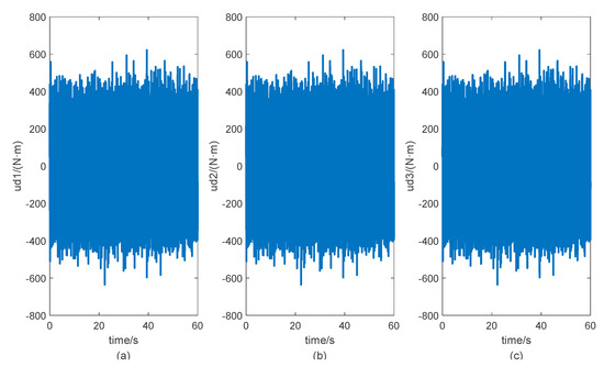
Figure 4.
Curves of the disturbances. (a) Curve of disturbance input of Agent 1. (b) Curve of disturbance input of Agent 2. (c) Curve of disturbance input of Agent 3.
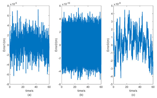
Figure 5.
Curves of the error signals without faults. (a) Curve of error signal without faults of Agent 1. (b) Curve of error signal without faults of Agent 2. (c) Curve of error signal without faults of Agent 3.
5.2. Actuators with Faults
Under the noise signals shown in Figure 4, the fault signals of the three actuators are shown in Figure 6. The simulated fault information of the heterogeneous multi-agent refers to the disturbance torque of each actuator. In order to verify the effectiveness of this method in theory, different fault signals are given to three actuators at t = 30 s and t = 40 s, respectively. It is assumed that the actuators are affected by the disturbance torque shown in the figure at the moment. These disturbance torques are the additional torque generated after the occurrence of the fault, corresponding to the disturbance torque in the three models.
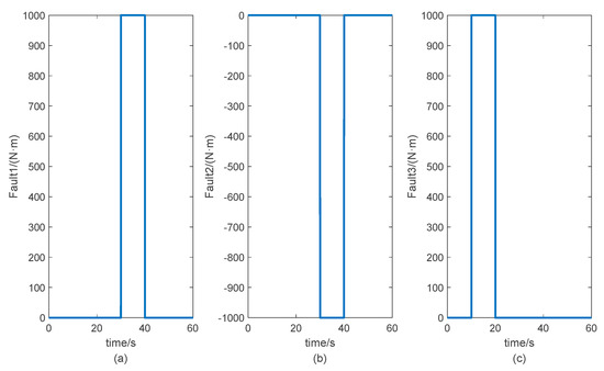
Figure 6.
Curves of the faults. (a) Curve of fault of Agent 1. (b) Curve of fault of Agent 2. (c) Curve of fault of Agent 3.
Beginning with the output estimation error, the final fault information is obtained through the corresponding threshold design according to the proposed algorithm. According to the proposed algorithm and the given parameters in this paper, the error signal of each agent that can be obtained for Agent 1 is shown in Figure 7. It can be seen from the figure that, when each agent has a fault, Agent 1 can obtain an accurate fault signal; that is, the three error signals are outside the threshold of the error signal given in Section 5.1 at the time of the fault. For Agent 2 and Agent 3, the process of diagnosing their related agent faults according to the proposed algorithm is similar and, therefore, is presented in Figure 8 and Figure 9. As shown in Figure 8 and Figure 9, given the same fault signal, the value of the error exceeds the threshold. Agent 2 and Agent 3 can both diagnose the fault of the related agents. The output estimate errors of Agent 2 and Agent 3 are better than that of Agent 1 because of the influence of model parameters. The simulation results demonstrate that the heterogeneous multi-agent fault diagnosis algorithm based on the actuation system proposed in this paper can accurately and timely detect the fault signal of the associated actuator.
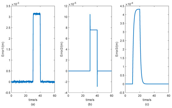
Figure 7.
Curves of the error signals with faults (Agent 1). (a) Curve of the error signal of Fault 1. (b) Curve of the error signal of Fault 2. (c) Curve of the error signal of Fault 3.
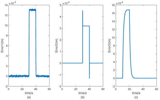
Figure 8.
Curves of the error signals with faults (Agent 2). (a) Curve of the error signal of Fault 1. (b) Curve of the error signal of Fault 2. (c) Curve of the error signal of Fault 3.

Figure 9.
Curves of the error signals with faults (Agent 3). (a) Curve of the error signal of Fault 1. (b) Curve of the error signal of Fault 2. (c) Curve of the error signal of Fault 3.
To better illustrate the effectiveness of the proposed method, a simulation verification on the two key parameters that affect the diagnosis performance is carried out. The simulation statistical results are shown in Table 1 and Table 2. The result in the table is “OK”, which indicates that there is a feasible solution to the LMI inequality, and the fault information can be diagnosed accurately. If the result is “NO”, the LMI inequality cannot obtain a feasible solution with this parameter, and the corresponding fault information cannot be accurately diagnosed.

Table 1.
The verification of parameter .

Table 2.
The verification of parameter .
It can be seen that the parameter has greater influence on the results, whereas the parameter has less influence. One reason is that the order of magnitude of the model parameters in the state matrix of the three actuators models is large. The other reason is that the parameter differences between different actuator models are also great. Therefore, there are requirements on the value of parameter of the fault diagnosis algorithm.
6. Conclusions
This paper proposes a heterogeneous multi-agent fault diagnosis method of a large aircraft actuation system. The proposed method is employed to realize the fault diagnosis of each actuator and its associated actuator; that is, the effective fault diagnosis can be realized by measuring the output signal. The proposed method does not require the actuator model to have the same order. Fault diagnosis can be realized through mutual information interaction and a given error signal threshold. Simulation experiments are conducted to evaluate the effectiveness of the proposed method. The obtained results demonstrate that the proposed method has a wider diagnosis range and higher adaptability than the traditional bit fault diagnosis method of actuators, which provides a theoretical basis for the actuator health management of subsequent large aircraft.
Author Contributions
Conceptualization, Y.C. and T.L.; methodology, Y.C.; software, Y.C.; validation, T.L. and Y.L.; writing—original draft preparation, Y.C.; writing—review and editing, T.L.; supervision, X.W. All authors have read and agreed to the published version of the manuscript.
Funding
This research was funded by the National Natural Science Foundation of China (No. 61703341), Aeronautical Science Foundation of China (No. 20180753006), Natural Science Foundation of Shaanxi Province (2020JQ-218), and Shaanxi Province Key Laboratory of Flight Control and Simulation Technology.
Institutional Review Board Statement
Not applicable.
Informed Consent Statement
Not applicable.
Data Availability Statement
Not applicable.
Conflicts of Interest
The authors declare no conflict of interest.
References
- Rosero, J.A.; Ortega, J.A.; Aldabas, E.; Romeral, L. Moving Towards A More Electric Aircraft. IEEE Aerosp. Electron. Syst. Mag. 2007, 22, 3–9. [Google Scholar] [CrossRef] [Green Version]
- Ding, S.X. Model-Based Fault Diagnosis Techniques: Design Schemes, Algorithms, and Tools; Springer: Berlin/Heidelberg, Germany, 2013. [Google Scholar]
- Shen, Y.; Ding, S.X.; Haghani, A.; Hao, H.; Zhang, P. A Comparison Study of Basic Data-Driven Fault Diagnosis and Process Monitoring Methods on the Benchmark Tennessee Eastman Process. J. Process Control. 2012, 22, 1567–1581. [Google Scholar]
- Zhonghai, M.A.; Shaoping, W.A.; Jian, S.H.; Tongyang, L.I.; Xingjian, W.A. Fault Diagnosis of an Intelligent Hydraulic Pump Based on a Nonlinear Unknown Input Observer. Chin. J. Aeronaut. 2018, 31, 385–394. [Google Scholar]
- Xu, Q.-N.; Lee, K.-M.; Zhou, H.; Yang, H.-Y. Model-Based Fault Detection and Isolation Scheme for a Rudder Servo System. IEEE Trans. Ind. Electron. 2015, 62, 2384–2396. [Google Scholar] [CrossRef]
- Doraiswami, R.; Cheded, L. A Novel Identification Scheme for Physical Systems with Applications to System Health Monitoring. In Proceedings of the 15th IFAC Symposium on Information Control Problems in Manufacturing, Ottawa, ON, Canada, 11–13 May 2015. [Google Scholar]
- Balaban, E.; Saxena, A.; Narasimhan, S.; Roychoudhury, I.; Koopmans, M.; Ott, C.; Goebel, K. Prognostic Health-Management System Development for Electromechanical Actuators. J. Aerosp. Inf. Syst. 2015, 12, 329–344. [Google Scholar] [CrossRef] [Green Version]
- Mazzoleni, M.; Maroni, G.; Maccarana, Y.; Formentin, S.; Previdi, F. Fault Detection in Airliner Electro-Mechanical Actuators via Hybrid Particle Filtering. In Proceedings of the 20th World Congress, the International Federation of Automatic Control, Toulouse, France, 9–14 July 2017. [Google Scholar]
- Lu, C.; Wang, S.; Wang, X. A Multi-Source Information Fusion Fault Diagnosis for Aviation Hydraulic Pump Based on the New Evidence Similarity Distance. Aerosp. Sci. Technol. 2017, 71, 392–401. [Google Scholar] [CrossRef]
- Ramos, A.R.; da Neto, A.J.; Llanes-Santiago, O. An Approach to Fault Diagnosis with Online Detection of Novel Faults Using Fuzzy Clustering Tools. Expert Syst. Appl. 2018, 113, 200–212. [Google Scholar] [CrossRef]
- Bartyś, M.; Patton, R.; Syfert, M.; Heras, S.D.L.; Quevedo, J. Introduction to the DAMADICS Actuator FDI Benchmark Study. Control Eng. Pr. 2006, 14, 577–596. [Google Scholar] [CrossRef]
- Lu, C.; Yuan, H.; Ma, J. Fault detection, Diagnosis, and Performance Assessment Scheme for Multiple Redundancy Aileron Actuator. Mech. Syst. Signal Process 2018, 113, 199–221. [Google Scholar] [CrossRef]
- Sharifi, S.; Tivay, A.; Rezaei, S.M.; Zareinejad, M.; Mollaei-Dariani, B. Leakage Fault Detection in Electro-Hydraulic Servo Systems Using a Nonlinear Representation Learning Approach. ISA Trans. 2018, 73, 154–164. [Google Scholar] [CrossRef]
- Nahid-Mobarakeh, B.; Simoes, M.G. Multi-Agent Based Fault Detection and Isolation in More Electric Aircraft. In Proceedings of the 2013 IEEE Industry Applications Society Annual Meeting, Lake Buena Vista, FL, USA, 6–11 October 2013. [Google Scholar]
- Ren, W.; Beard, R.W.; Atkins, E.M. Information Consensus in Multivehicle Cooperative Control. IEEE Control. Syst. Mag. 2007, 27, 71–82. [Google Scholar]
- Sridhar, S.; Hahn, A.; Govindarasu, M. Cyber–Physical System Security for the Electric Power Grid. Proc. IEEE 2011, 100, 210–224. [Google Scholar] [CrossRef]
- Tang, Y.; Xing, X.; Karimi, H.R.; Kocarev, L.; Kurths, J. Tracking Control of Networked Multi-Agent Systems under New Characterizations of Impulses and Its Applications in Robotic Systems. IEEE Trans. Ind. Electron. 2016, 63, 1299–1307. [Google Scholar] [CrossRef]
- Menon, P.P.; Edwards, C. Robust Fault Estimation Using Relative Information in Linear Multi-Agent Networks. IEEE Trans. Autom. Control. 2014, 59, 477–482. [Google Scholar] [CrossRef] [Green Version]
- Chen, X.; Zhang, K.; Jiang, B. Finite-Time Unknown Input Observer-Based Distributed Fault Diagnosis for Multi-agent Systems with Disturbances. Circuits Syst. Signal Process. 2018, 11, 4215–4233. [Google Scholar] [CrossRef]
- Shames, I.; Teixeira, A.M.H.; Sandberg, H.; Johansson, K.H. Distributed Fault Detection for Interconnected Second-Order Systems. Automatica 2011, 47, 2757–2764. [Google Scholar] [CrossRef] [Green Version]
- Meskin, N.; Davoodi, M.; Khorasani, K. Simultaneous Fault Detection and Consensus Control Design for a Network of Multi-Agent Systems. Automatica 2016, 66, 185–194. [Google Scholar]
- Davoodi, M.R.; Khorasani, K.; Talebi, H.A.; Momeni, H.R. Distributed Fault Detection and Isolation Filter Design for a Network of Heterogeneous Multiagent Systems. IEEE Trans. Control. Syst. Technol. 2013, 22, 1061–1069. [Google Scholar] [CrossRef]
- Li, Y.; Fang, H.; Chen, J.; Shang, C. Distributed Fault Detection and Isolation for Multi-Agent Systems Using Relative Information. In Proceedings of the 2016 American Control Conference (ACC), Boston, MA, USA, 6–8 July 2016. [Google Scholar]
- Chadli, M.; Davoodi, M.; Meskin, N. Distributed State Estimation, Fault Detection and Isolation Filter Design for Heterogeneous Multi-Agent Linear Parameter-Varying Systems. IET Control Theory Appl. 2017, 11, 254–262. [Google Scholar] [CrossRef]
- Quan, Y.; Chen, W.; Wu, Z.; Peng, L. Observer-Based Distributed Fault Detection and Isolation for Heterogeneous Discrete-Time Multi-Agent Systems with Disturbances. IEEE Access 2016, 4, 4652–4658. [Google Scholar] [CrossRef] [Green Version]
- Cheng, W.; Zhang, K.; Jiang, B.; Ding, S.X. Fixed-Time Fault-Tolerant Formation Control for Heterogeneous Multi-Agent Systems with Parameter Uncertainties and Disturbances. IEEE Trans. Circuits Syst. I Regul. Pap. 2021, 68, 2121–2133. [Google Scholar] [CrossRef]
- Wang, P.; Zou, P.; Yu, C.; Sun, J. Distributed Fault Detection and Isolation for Uncertain Linear Discrete Time-Varying Heterogeneous Multi-Agent Systems. Inf. Sci. 2021, 579, 483–507. [Google Scholar] [CrossRef]
- Mo, L.; Yu, Y.; Ren, G.; Yuan, X. Constrained Consensus of Continuous-Time Heterogeneous Multi-Agent Networks with Nonconvex Constraints and Delays. J. Syst. Sci. Complex. 2022, 35, 105–122. [Google Scholar] [CrossRef]
- Yang, K.; Wang, X. Team-Based Blanket Coverage Control for Heterogeneous Multi-Agent Systems. In Proceedings of the 39th Chinese Control Conference (CCC), Shenyang, China, 27–29 July 2020. [Google Scholar]
- Gahinet, P.; Apkarian, P. A Linear Matrix Inequality Approach to H∞ Control. Int. J. Robust Nonlinear Control. 1994, 4, 421–448. [Google Scholar] [CrossRef]
- Semsar-Kazerooni, E.; Khorasani, K. Optimal Consensus Algorithms for Cooperative Team of Agents Subject to Partial Information. Automatica 2008, 44, 2766–2777. [Google Scholar] [CrossRef]
- Rehman, W.U.; Wang, S.; Wang, X.; Fan, L.; Shah, K.A. Motion Synchronization in a Dual Redundant HA/EHA System by Using a Hybrid Integrated Intelligent Control Design. Chin. J. Aeronaut. 2016, 29, 789–798. [Google Scholar] [CrossRef] [Green Version]
- Wang, X.; Liao, R.; Shi, C.; Wang, S. Linear Extended State Observer-Based Motion Synchronization Control for Hybrid Actuation System of More Electric Aircraft. Sensors 2017, 17, 2444. [Google Scholar] [CrossRef] [Green Version]
Publisher’s Note: MDPI stays neutral with regard to jurisdictional claims in published maps and institutional affiliations. |
© 2022 by the authors. Licensee MDPI, Basel, Switzerland. This article is an open access article distributed under the terms and conditions of the Creative Commons Attribution (CC BY) license (https://creativecommons.org/licenses/by/4.0/).