
Control Strategies for Highly Gyroscopic Outer Rotors with Diametral Enlargement in Active Magnetic Bearings


Abstract
:1. Introduction
2. Materials and Methods
3. Analytical Model of the System
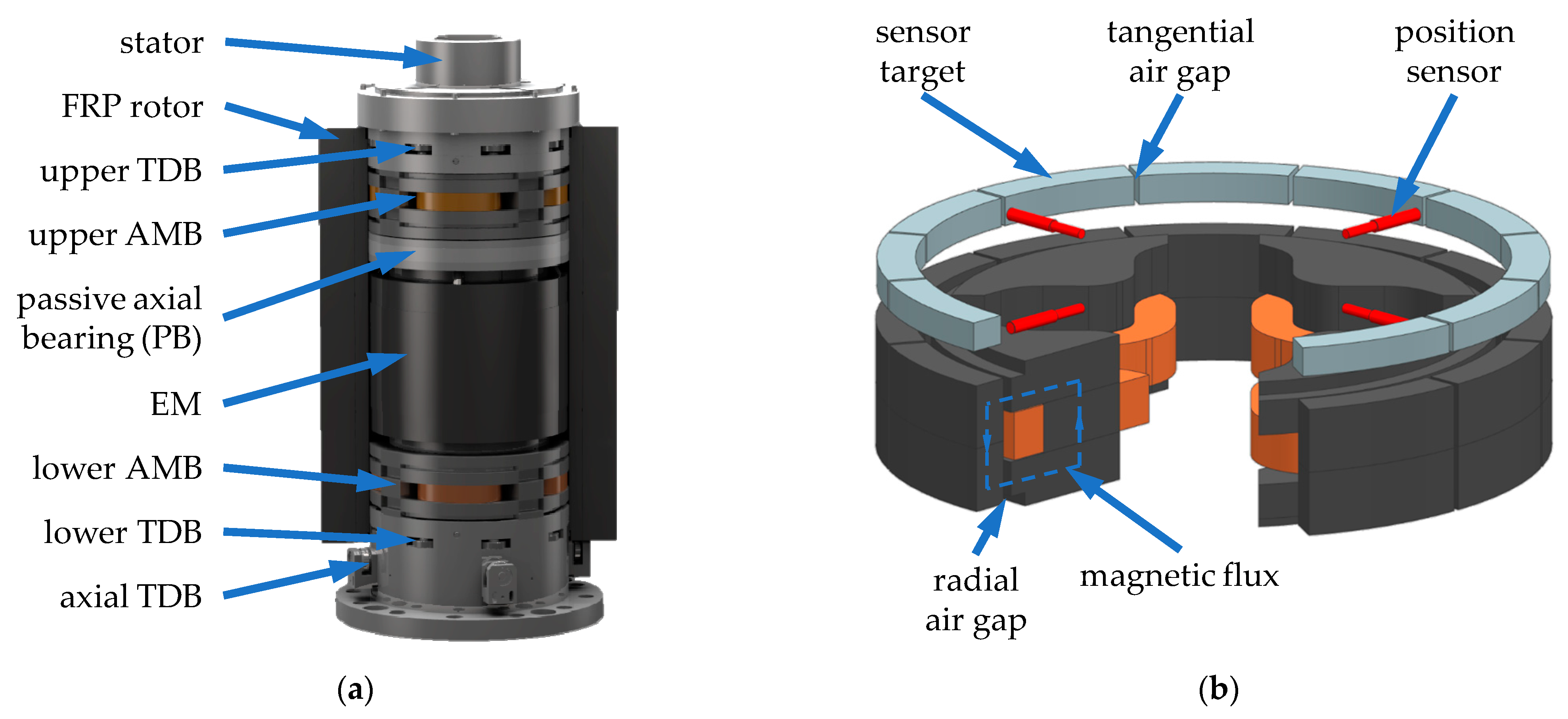
3.1. Active Magnetic Bearing (AMB)
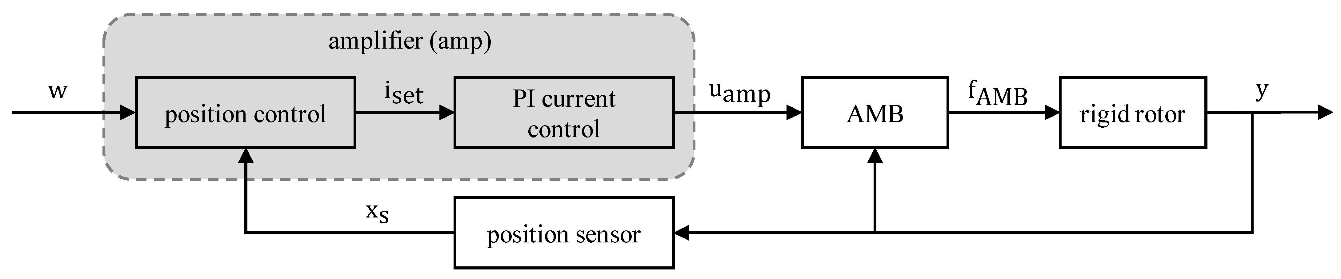
3.2. Amplifier
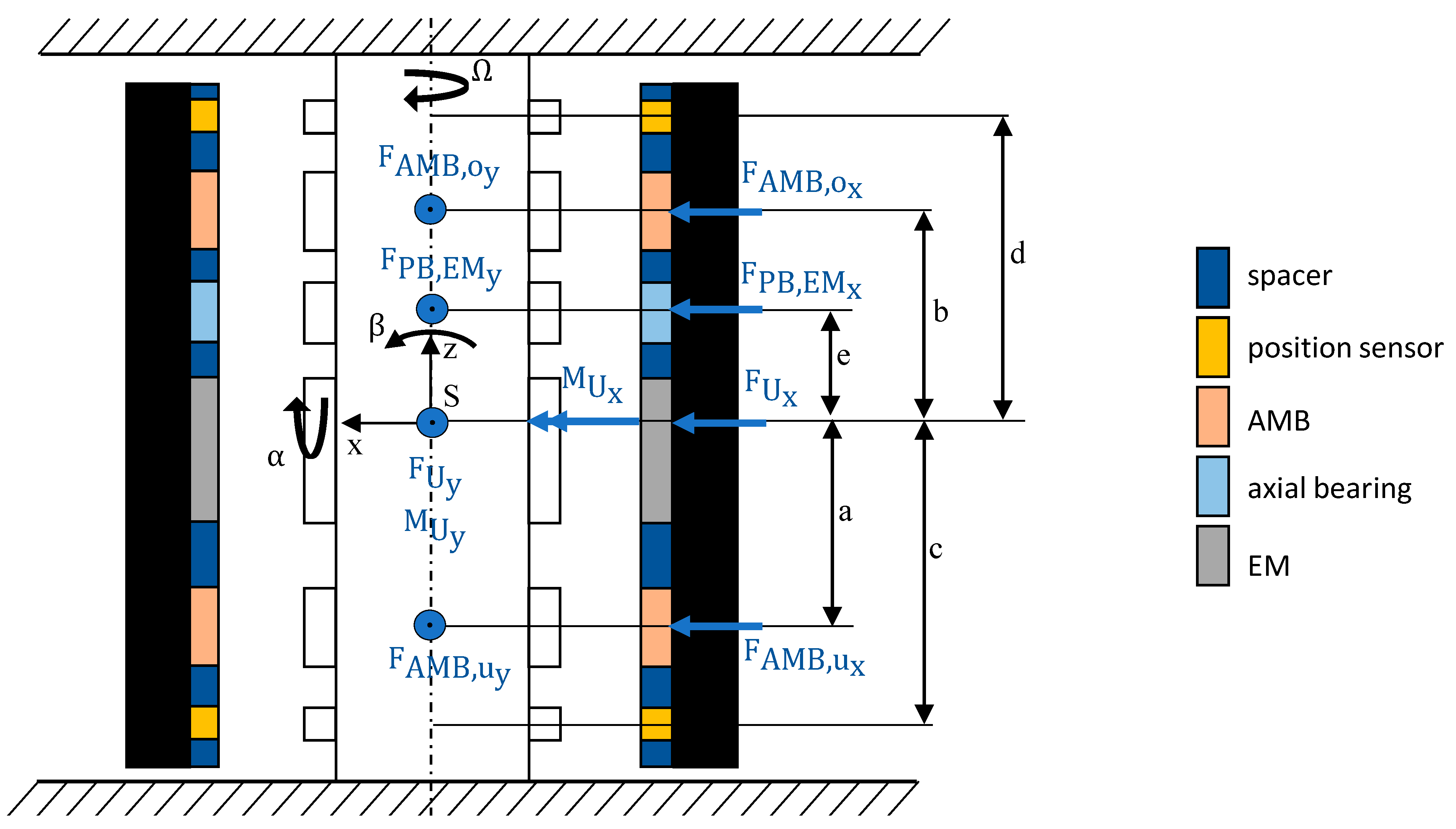
3.3. Rotor
3.4. Position Control
3.5. Model of the Electromechanical System
4. Benefits and Drawbacks of Diametral Enlargement of the Rotor and Their Bypassing
- Larger electromagnets, hence, an increased number of windings n, are required to generate the same maximum force Fmax;
- Higher copper losses/increasing resistance R of the coil windings due to increased number of windings n;
- Decreasing maximum amplitude of force max (ω) for ω > ωsat (see Equation (11)).
- Benefits of an increasing air gap s(Ω) include the following:
- Increasing driving range of the actuator ωsat (see Equation (10)).
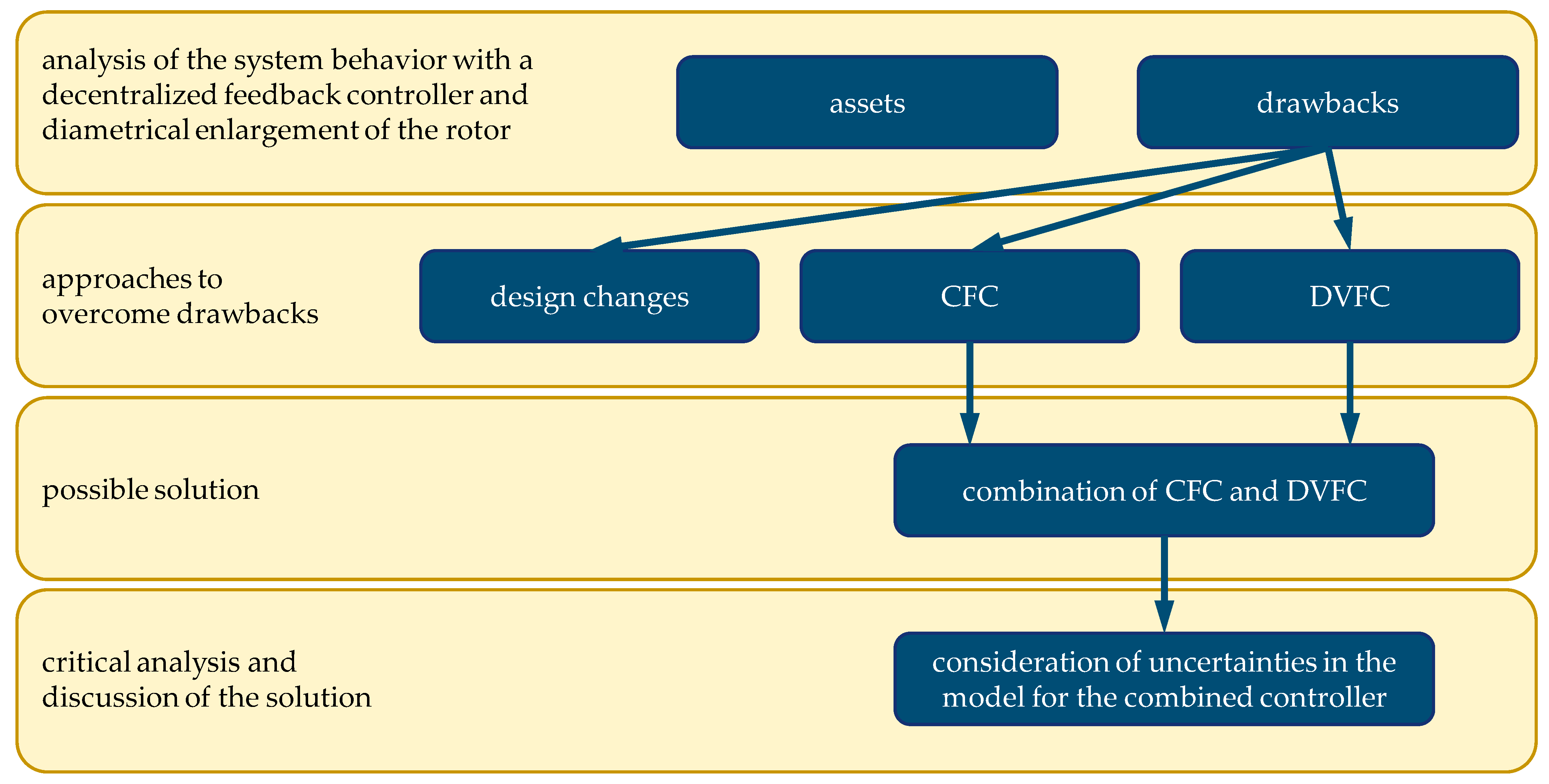
5. Approaches to Deal with the Gyroscopic Behavior and the Rotor Enlargement
5.1. Design Changes
5.2. Cross Feedback Controller (CFC)
5.3. Decentralized Variable Feedback Control (DVFC)
6. Combination of Decentralized Variable Feedback Control and Cross Feedback Control
7. Conclusions
- By using the cross feedback control, the gyroscopic-induced split-up of the conical body eigenfrequencies is reduced and the critical speeds shift towards lower rotational speeds, thus leading to a higher operational range.
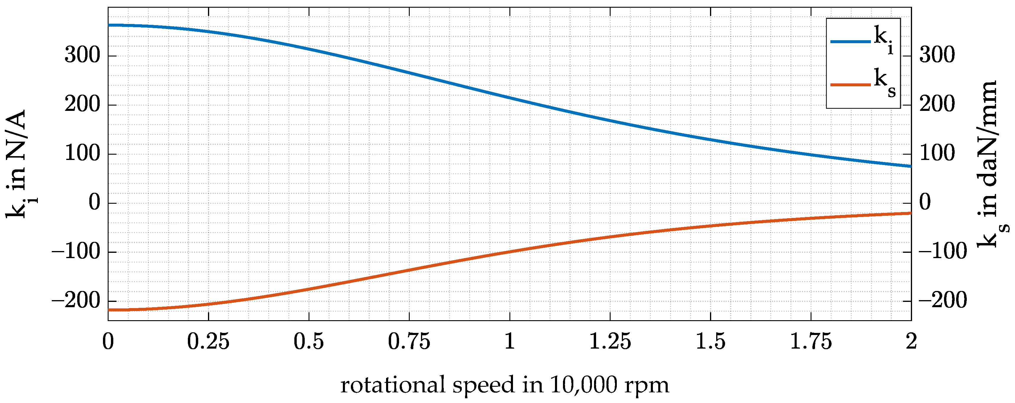
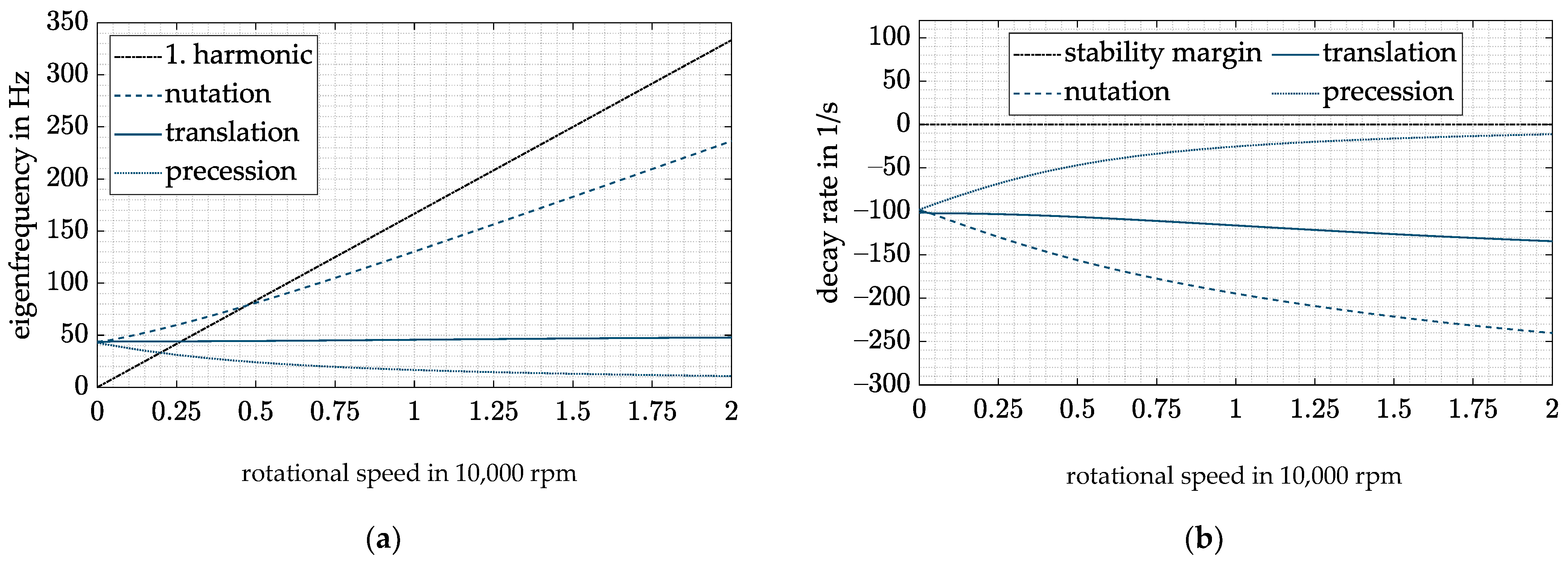
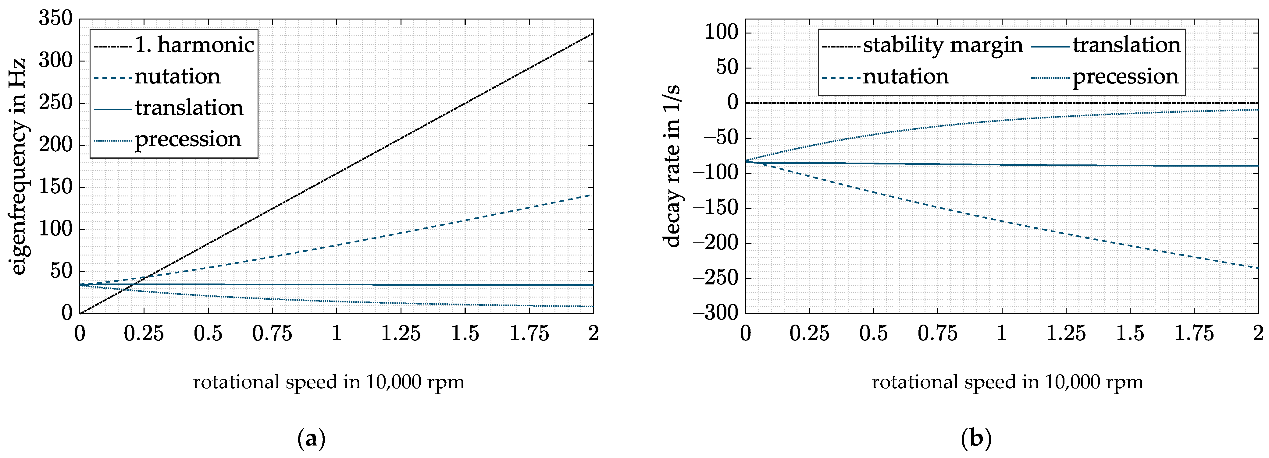
- Speed-dependent feedback terms P(Ω) and D(Ω) are used to compensate the speed dependency of the stiffness and damping of the AMB. As a result, the natural frequency of the rigid-body eigenmodes can be shifted to lower frequencies and the operating range of the system is increased. At the same time, the damping at low speeds is reduced, and thus no overcompensation occurs.
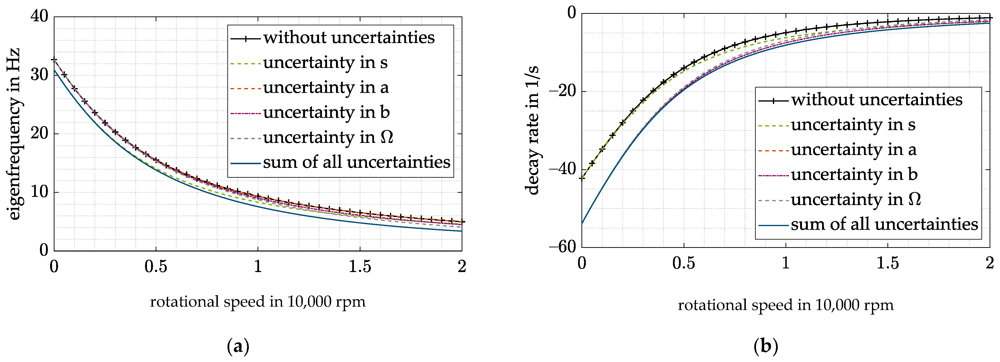
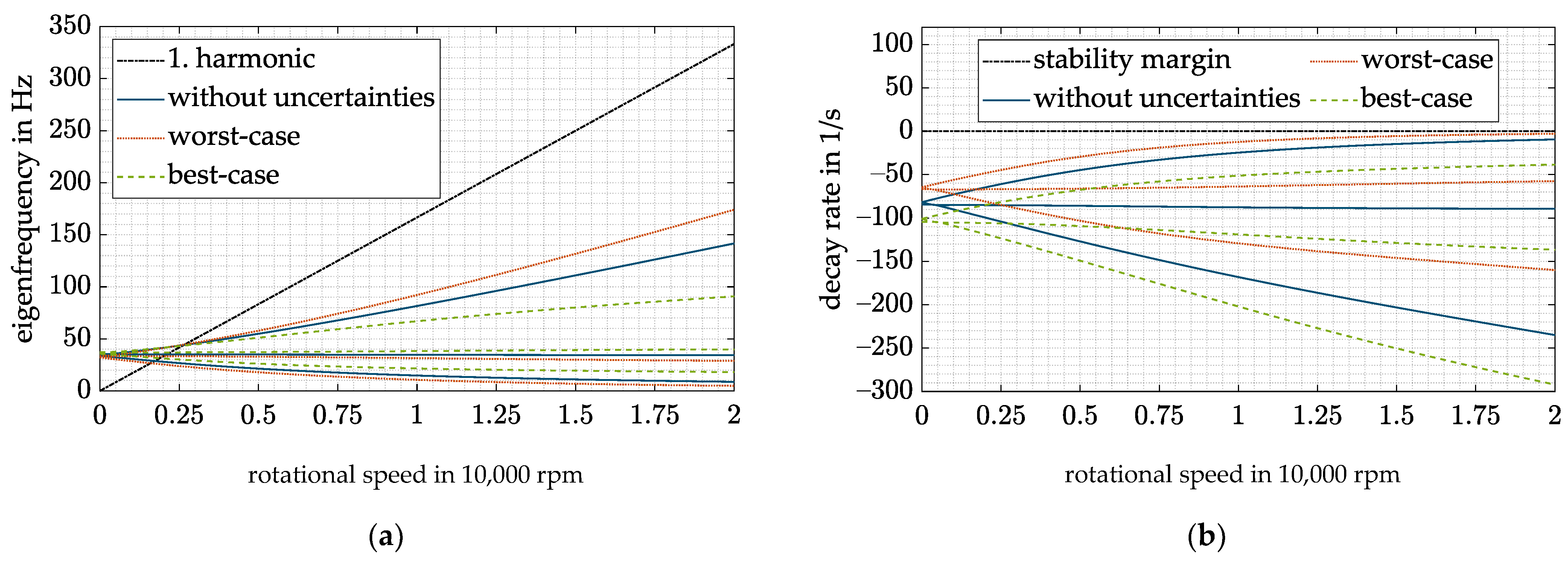
- Even with uncertainties in the estimated air gap, the proposed controller can stabilize the system.
- Due to this combined controller, the critical speed of the nutation can be reduced by approximately 4500 rpm for the investigated system. At the same time, the undesired high decay rate at low frequencies is avoided.
- To change from a conventional DFC to the proposed controller, the rotational speed has to be measured. However, in most systems, the rotational speed is measured anyway, and therefore no increased measurement effort is necessary for the new control approach.
Author Contributions
Funding
Institutional Review Board Statement
Informed Consent Statement
Data Availability Statement
Acknowledgments
Conflicts of Interest
References
- Amiryar, M.; Pullen, K. A Review of Flywheel Energy Storage System Technologies and Their Applications. Appl. Sci. 2017, 7, 286. [Google Scholar] [CrossRef] [Green Version]
- Franz, D.; Richter, M.; Schneider, M.; Rinderknecht, S. Homopolar Active Magnetic Bearing Design for Outer Rotor Kinetic Energy Storages. In Proceedings of the 2019 IEEE International Electric Machines & Drives Conference (IEMDC), San Diego, CA, USA, 12–15 May 2019; pp. 774–778, ISBN 978-1-5386-9350-6. [Google Scholar]
- Schneider, M. Ganzheitlicher Modellbasierter Entwurf von Kinetischen Energiespeichern in Außenläuferbauform, (Translated: Holistic Model Based Design of Outer Rotor Kinetic Energy Storage Systems); Shaker Verlag: Düren, Germany, 2019; ISBN 9783844066579. [Google Scholar]
- Quurck, L.; Richter, M.; Schneider, M.; Franz, D.; Rinderknecht, S. Design and practical Realization of an innovative Flywheel Concept for industrial Applications. Tech. Mech. 2017, 37, 151–160. [Google Scholar] [CrossRef]
- Quurck, L.; Franz, D.; Schüßler, B.; Rinderknecht, S. Planetary Backup Bearings for High Speed Applications and Service Life Estimation Methodology. Mech. Eng. J. 2017, 4, 17-00010. [Google Scholar] [CrossRef] [Green Version]
- Schüßler, B.; Hopf, T.; Rinderknecht, S. Drop-Downs of an Outer Rotor Flywheel in Different Planetary Touch-Down Bearing Designs. Actuators 2022, 11, 30. [Google Scholar] [CrossRef]
- Cao, H.; Zhang, X.; Chen, X. The Concept and Progress of Intelligent Spindles: A Review. Int. J. Mach. Tools Manuf. 2017, 112, 21–52. [Google Scholar] [CrossRef]
- Kern, S.; Schiffler, A.; Nordmann, R.; Abele, E. Modelling and Active Damping of a Motor Spindle with Speed-Dependent Dynamics. In Proceedings of the 9th International Conference on Vibrations in Rotating Machinery, Exeter, UK, 8–10 September 2008. [Google Scholar]
- Knospe, C.R. Active Magnetic Bearings for Machining Applications. Control Eng. Pract. 2007, 15, 307–313. [Google Scholar] [CrossRef]
- Li, D.; Cao, H.; Shi, F.; Zhang, X.; Chen, X. Model Predictive Control Based Chatter Suppression in Milling Process via Piezoelectric Stack Actuators. Procedia CIRP 2018, 78, 31–36. [Google Scholar] [CrossRef]
- Li, D.; Cao, H.; Zhang, X.; Chen, X.; Yan, R. Model predictive control based active chatter control in milling process. Mech. Syst. Signal Processing 2019, 128, 266–281. [Google Scholar] [CrossRef]
- Kuseyri, İ.S. Robust control and unbalance compensation of rotor/active magnetic bearing systems. J. Vib. Control 2012, 18, 817–832. [Google Scholar] [CrossRef]
- Siva Srinivas, R.; Tiwari, R.; Kannababu, C. Application of active magnetic bearings in flexible rotordynamic systems—A state-of-the-art review. Mech. Syst. Signal Processing 2018, 106, 537–572. [Google Scholar] [CrossRef]
- Schüßler, B.; Hopf, T.; Fanz, D.; Schneider, M.; Rinderknecht, S. High Speed Drop Down in a Planetary Touch-Down Bearing of an Outer Rotor Flywheel System. In Proceedings of the SIRM 2021, The 14th International Conference on Dynamics of Rotating Machines, Gdańsk, Poland, 17–19 February 2021. [Google Scholar]
- Lyu, X.; Di, L.; Yoon, S.Y.; Lin, Z.; Hu, Y. A platform for analysis and control design: Emulation of energy storage flywheels on a rotor-AMB test rig. Mechatronics 2016, 33, 146–160. [Google Scholar] [CrossRef]
- Ahrens, M.; Kucera, L.; Larsonneur, R. Performance of a magnetically suspended flywheel energy storage device. IEEE Trans. Contr. Syst. Technol. 1996, 4, 494–502. [Google Scholar] [CrossRef]
- Tang, J.; Zhao, S.; Wang, Y.; Wang, K. High-speed Rotor’s Mechanical Design and Stable Suspension Based on Inertia-ratio for Gyroscopic Effect Suppression. Int. J. Control Autom. Syst. 2018, 16, 1577–1591. [Google Scholar] [CrossRef]
- Ahrens, M.; Kucera, L. Cross Feedback Control of a Magnetic Bearing System: Controller Design Considering Gyroscopic Effects. In Proceedings of the 3rd International Symposium on Magnetic Suspension Technology, Tallahassee, FL, USA, 13–15 December 1995; pp. 177–191. [Google Scholar]
- Fang, J.; Xu, X.; Xie, J. Active vibration control of rotor imbalance in active magnetic bearing systems. J. Vib. Control 2015, 21, 684–700. [Google Scholar] [CrossRef]
- Hutterer, M.; Hofer, M.; Nenning, T.; Schrödl, M. LQG Control of an Active Magnetic Bearing with a Special Method to consider the Gyroscopic Effect. In Proceedings of the ISMB 14, International Symposium on Magnetic Bearings, Linz, Austria, 11–14 August 2014; pp. 54–59. [Google Scholar]
- Hutterer, M.; Hofer, M.; Schrodl, M. Decoupled control of an active magnetic bearing system for a high gyroscopic rotor. In Proceedings of the 2015 IEEE International Conference on Mechatronics (ICM), Nagoya, Japan, 6–8 March 2015; pp. 210–215, ISBN 978-1-4799-3633-5. [Google Scholar]
- Hutterer, M.; Schrödl, M. Control of Active Magnetic Bearings in Turbomolecular Pumps for Rotors with Low Resonance Frequencies of the Blade Wheel. Lubricants 2017, 5, 26. [Google Scholar] [CrossRef] [Green Version]
- Barbaraci, G.; Pesch, A.H.; Sawicki, J.T. Experimental Investigations of Minimum Power Consumption Optimal Control for Variable Speed AMB Rotor. In Volume 8: Dynamic Systems and Control, Parts A and B. Proceedings of the ASME 2010 International Mechanical Engineering Congress and Exposition, Vancouver, British Columbia, Canada, 12–18 November 2010; ASMEDC, 11122010; ASME: New York, NY, USA, 2010; pp. 1047–1056. ISBN 978-0-7918-4445-8. [Google Scholar]
- Steyn, S.J.M.; van Schoor, G.; van Vuuren, P.A. Multivariable H∞ Control for an Active Magnetic Bearing Flywheel System. In Proceedings of the UKACC International Conference on CONTROL 2010, Coventry, UK, 7–10 September 2010; Institution of Engineering and Technology: Stevenage, UK, 2010; pp. 1014–1019, ISBN 978-1-84600-038-6. [Google Scholar]
- Zhang, W.; Cheng, L.; Zhu, H. Suspension Force Error Source Analysis and Multidimensional Dynamic Model for a Centripetal Force Type-Magnetic Bearing. IEEE Trans. Ind. Electron. 2020, 67, 7617–7628. [Google Scholar] [CrossRef]
- Kuseyri, İ.S. Adaptive Vibration Control of Rotors with Active Magnetic Bearings. J. Vib. Eng. Technol. 2017, 5, 159–164. [Google Scholar]
- Tang, J.; Ning, M.; Cui, X.; Wei, T.; Zhao, X. PIDNN control for Vernier-gimballing magnetically suspended flywheel under nonlinear change of stiffness and disturbance. Proc. Inst. Mech. Eng. Part I J. Syst. Control Eng. 2021, 235, 1100–1112. [Google Scholar] [CrossRef]
- Apkarian, P.; Gahinet, P.; Buhr, C. Multi-model, multi-objective tuning of fixed-structure controllers. In Proceedings of the 2014 European Control Conference (ECC), Strasbourg, France, 24–27 June 2014; pp. 856–861. [Google Scholar]
- Magnetic Bearings: Theory, Design, and Application to Rotating Machinery; Maslen, E.H.; Schweitzer, G. (Eds.) Springer: Berlin/Heidelberg, Germany, 2009; ISBN 978-3-642-00496-4. [Google Scholar]
- Genta, G. Dynamics of Rotating Systems; Springer: New York, NY, USA, 2005; ISBN 9780387286877. [Google Scholar]
- Gasch, R.; Nordmann, R.; Pfützner, H. Rotordynamik, (Translated: Rotordynamic), 2nd ed.; Springer: Berlin/Heidelberg, Germany, 2006; ISBN 978-3-540-41240-3. [Google Scholar]
- Arnold, S.M.; Saleeb, A.F.; Al-Zoubi, N.R. Deformation and life analysis of composite flywheel disk systems. Compos. Part B Eng. 2002, 33, 433–459. [Google Scholar] [CrossRef]
- Meeker, D.C.; Maslen, E.H.; Noh, M.D. A wide bandwidth model for the electrical impedance of magnetic. In Proceedings of the Third International Symposium on Magnetic Suspension Technology, Tallahassee, FL, USA, 13–15 December 1996; Groom, N.J., Britcher, C.P., Eds.; NASA: Washington, WA, USA, 1996; pp. 387–401. [Google Scholar]
- Schoppa, A.; Delarbre, P. Soft Magnetic Powder Composites and Potential Applications in Modern Electric Machines and Devices. IEEE Trans. Magn. 2014, 50, 1–4. [Google Scholar] [CrossRef]
- Seifert, R.; Hofmann, W. Completion of analytical model of active magnetic thrust bearings including asymmetric air gap field between mixed materials. Mech. Eng. J. 2017, 4, 16–00696. [Google Scholar] [CrossRef]
- Traxler, A. Eigenschaften und AUSLEGUNG von Berührungsfreien Elektromagnetischen Lagern, (Translated: Characteristics and Design of Electromagnetic Bearings); ETH Zurich: Zurich, Switzerland, 1986. [Google Scholar]
- Bleuler, H. Decentralized Control of Magnetic Rotor Bearing Systems; ETH Zurich: Zurich, Switzerland, 1984. [Google Scholar]
- Li, G.; Maslen, E.H.; Allaire, P.E. A Note on ISO AMB Stability Margin. In Proceedings of the ISMB 10, International Symposium on Magnetic Bearings, Martigny, Switzerland, 21–23 August 2006. [Google Scholar]
- Che, J.; Zhu, Y.; Zhou, D.; He, X. Active fault tolerant control design using switching linear parameter varying controllers with inexact fault-effect parameters. Int. J. Robust Nonlinear 2022. [Google Scholar] [CrossRef]
- Peng, C.; Zhu, M.; Wang, K.; Ren, Y.; Deng, Z. A Two-Stage Synchronous Vibration Control for Magnetically Suspended Rotor System in the Full Speed Range. IEEE Trans. Ind. Electron. 2020, 67, 480–489. [Google Scholar] [CrossRef]


Publisher’s Note: MDPI stays neutral with regard to jurisdictional claims in published maps and institutional affiliations. |
© 2022 by the authors. Licensee MDPI, Basel, Switzerland. This article is an open access article distributed under the terms and conditions of the Creative Commons Attribution (CC BY) license (https://creativecommons.org/licenses/by/4.0/).
Share and Cite
Hopf, T.; Richter, M.; Schüßler, B.; Rinderknecht, S. Control Strategies for Highly Gyroscopic Outer Rotors with Diametral Enlargement in Active Magnetic Bearings. Actuators 2022, 11, 91. https://doi.org/10.3390/act11030091
Hopf T, Richter M, Schüßler B, Rinderknecht S. Control Strategies for Highly Gyroscopic Outer Rotors with Diametral Enlargement in Active Magnetic Bearings. Actuators. 2022; 11(3):91. https://doi.org/10.3390/act11030091
Chicago/Turabian StyleHopf, Timo, Michael Richter, Benedikt Schüßler, and Stephan Rinderknecht. 2022. "Control Strategies for Highly Gyroscopic Outer Rotors with Diametral Enlargement in Active Magnetic Bearings" Actuators 11, no. 3: 91. https://doi.org/10.3390/act11030091
APA StyleHopf, T., Richter, M., Schüßler, B., & Rinderknecht, S. (2022). Control Strategies for Highly Gyroscopic Outer Rotors with Diametral Enlargement in Active Magnetic Bearings. Actuators, 11(3), 91. https://doi.org/10.3390/act11030091