Abstract
Passive rotors are often limited in rotational speed due to bearing constraints, stability and excessive vibration levels. To address the vibration issue, Active Magnetic Bearings (AMBs) levitating the rotor with a magnetic field can be used. They offer a clearance and variable stiffness and damping to the rotor support, which help to mitigate greatly the vibration issue. However, they are also limited at large rotational speed because of the high frequency control force required to levitate the rotor safely. To overcome the frequency limitation, a dual AMBs/internal bending control concept is investigated with associated modelling and control algorithms. This approach is examined in simulation with a 19 kg rotor running up to 10,000 RPM, where three resonance frequencies are present at 2700, 5300, and 9300 RPM, with the first resonant frequency being the most strongly excited. Using internal rotor bending control, a maximum radial displacement of 15 for the rotor mid-point is achieved, which gives a reduction in vibration amplitude of 45% compared to the case of no control. Variations of the algorithm are presented and discussed, showing the potential of the proposed approach.
1. Introduction
High speed rotating machines have many crucial industrial applications, however, they can exhibit detrimental vibrations. Therefore, a rotating system must be carefully designed so that it can fulfil its function without disturbing its surroundings. Vibrations can arise from multiple sources, including manufacturing tolerances, which lead to an inherent unbalanced state, thermal gradients along the rotor generating bend, or external disturbances. High levels of vibrations are a concern, as they can potentially reduce the life expectancy of the components, generate noise or close necessary clearances.
The simplest vibration reduction strategy is balancing [1], which can be done passively or actively, and has the advantage of reducing the principal source of vibration. Passive approaches, such as adding or removing mass [2,3], or more advanced passive ball balancing used in applications such as hard-disk drives [4,5,6,7], do not require actuation. However, they may be inadequate for machines that have a changing mass distribution resulting from transient thermal effects, or mass loss. Active balancing addresses this issue by employing actuators and a control system that react in real-time to the balance conditions of the shaft. An example of this approach is using motorised rotary discs with heavy spots to cancel out the unbalance [8,9,10,11]. In case of the disturbance force generating the vibration not being linked to the unbalance, other methods must be used, for example, modification of the rotating element. Successful approaches include coupling piezoelectric actuators to the rotor surface [12,13,14], taking advantage of their force capacity, high frequency and compact geometry. The rotor itself can also be made with a material containing a fraction of active piezoelectric material, with functionally graded materials [15,16,17,18], or macro fibre composite [19]. These solutions, although successful in some regards, greatly increase the manufacturing cost and complexity, and show limited force capabilities in the case of high speed and heavy rotor application.
When it is not possible to modify the rotor, external actuators acting on the shaft can be used to mitigate any vibrations. Electromagnetic actuators are commonly used as they can apply high forces at high frequency without being in contact with the rotor [20,21]. Combining the actuation and rotor support, Active Magnetic Bearings (AMBs) can be used to mitigate vibrations for high speed machines, offering improved performance, even though they require the inclusion of amplifiers and sensors to control the rotor levitation. Indeed, AMBs have a much higher life expectancy compared to rolling element bearings, together with having a lubrication-free architecture particularly well suited to wide temperature ranges [22], operation in a vacuum and very high speed applications, such as flywheels [23,24]. The closed loop nature of AMB levitation allows tailoring of the controller to suit a given application, for example, with custom stiffness, damping and unbalance rejection [25,26]. Moreover, the power failure recovery procedures have been extensively studied, making the AMB a reliable bearing solution [27,28]. The control strategy of active systems is a large factor in their efficiency, with techniques such as fuzzy controllers [29], auto-tuning PIDs [30], sliding mode controllers [31] or H-infinity optimisation [32] being implemented.
The methods presented have compromises to focus on addressing a particular aspect of vibration control. Unbalance compensation cancels only the synchronous vibration, lacking the flexibility of outboard actuators. Piezoelectric elements in the rotating frame are limited in force and displacement, as well as requiring a constant high voltage supply through the rotor. For actuators located in the non-rotating frame actuating the rotor, such as electromagnetic actuators or AMBs, they require very high frequency capabilities to control the vibrations. To counter the unbalance force, the compensating magnetic force may have amplifier bandwidth limitations. In addition, unbalance force increases with the square of the rotating speed, which can also lead to magnetic flux saturation [33]. Also, advanced control strategies must be carefully designed to ensure stability and the controller hardware must be computationally fast enough to ensure determinism, which often means reduced order models have to be used.
The aim of this paper is to build upon the advantages of each method, whilst addressing the limitation they have in terms of flexibility, actuation frequency, force capabilities and power requirements. A novel rotor topology and actuation concept is proposed, consisting of actuators located within the rotor that are capable of applying counter-bend moments to straighten the rotor. Having actuators located on the rotating frame takes advantage of the low frequency required to control thermal bends, synchronous vibrations and their harmonics. They are designed to only use energy when adjusting the bend and utilise a braking system to maintain the bending force without using any power. The active nature of the system allows it to adapt itself using a control algorithm to respond to varying vibration conditions. The rotor is supported by AMBs to expand the control capabilities and demonstrate that the AMB system performance can be enhanced with the new active rotor, which can be internally controlled in order to appear rigid even above the flexible modes.
A schematic of the general rotor topology is shown in Figure 1. It consists of a central hollow rotor section, that hosts actuators capable of creating a controlled internal bending moment. Acting symmetrically along the middle radial plane of the rotor, the bending moment is applied at the couplings between the hollow active section and the passive support shafts of a smaller diameter. Laminated cores for the AMB and landing sleeves for the Touch-Down Bearings (TDBs) are assembled on the smaller passive shaft sections. The displacement measurement necessary to ensure stable levitation with the AMBs is taken via displacement sensors located between the AMBs and TDBs sleeves on both sides. The bending moments generated aim to reduce the rotor run-out and ensure clearances are within a given tolerance, without utilising the AMB system. It does so by adding a low energy, low frequency counter-bend to the rotor. The control algorithm is iterative and feed-forward with very low sampling frequency, designed to ensure stability and minimise the size and complexity of the on-board control system. This paper focuses on the feasibility and effectiveness of such a concept from a theoretical perspective, paving for way to an experimental prototype for validation. First, the model used to design the prototype is described, as well as the active control strategy. The resulting mode shapes and location are presented together with the results and a prototype render.

Figure 1.
Rotor schematic including the Active Magnetic Bearings (AMBs), the Touch-down Bearings (TDBs), and the displacement sensor locations.
2. Modelling Methodology
The theory behind each part of the full rotor dynamic model of the topology is presented. The model is centred on the three shaft sections, with one central large diameter active section and two smaller diameter passive sections on either sides, assembled with the coupling flanges and the sleeves for the AMBs and TDBs. The AMBs apply a levitation force at the core locations, while the bending actuators apply torques on the flanges between the shaft sections. The disturbance to counter here is the unbalance force.
2.1. Rotor Modelling
The rotor used in this analysis is 1222 mm long, with central external/internal diameters of 166/150 mm and sides external/internal diameters of 30/18 mm. The central section is made out of aluminium 7075, while the passive sections are steel, giving a total mass of 19 kg, including the internal actuator and the sleeves. The rotor is modelled using the method presented by Lalanne and Ferraris [34]. It is decomposed into 22 finite elements, as shown in Figure 2. Each node has four degrees of freedom; two translations and and two rotations and . The coordinate system used to parametrised each element is displayed on Figure 3.

Figure 2.
Finite element rotor decomposition into 22 Timoshenko elements and 23 nodes.
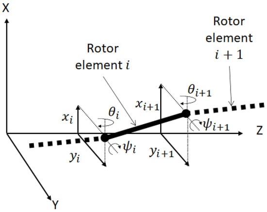
Figure 3.
Finite element coordinate system.
The displacements and rotations of each node are gathered in a generalised displacement vector expressed as
with the number of elements in which the rotor is decomposed. The shaft elements are modelled using Timoshenko beam theory, and participate both in the strain and the kinetic energies. The disks are considered rigid and will thus only participate to the kinetic energy. These disks are used to represent the sleeves for the TDBs and the AMBs, as well as the actuator system inside the rotor. Using the beam displacement functions ([34] (pp. 51–52)) and Equation (1), application of the Lagrange equations yields
where is the rotation speed of the rotor, is the vector of nodal external forces on each node and , , and are the generalised mass, gyroscopic, and stiffness matrices, respectively. The generalised matrices are a composition of the 8 by 8 mass, gyroscopic, and stiffness elemental matrices , , and in such a way that the four degrees of freedom of each adjacent nodes are coupled. The elemental matrices are defined in [34] and represent the link between the four degrees of freedom of two adjacent nodes.
2.2. Active Magnetic Bearing Modelling
A link between AMB input current, the rotor location and the force an AMB will exert on the rotor is formulated. The parameters of the AMBs used for the simulation can be found in Table 1.

Table 1.
AMBs parameters.
The AMBs are considered with differential driving, meaning that the opposing pole pairs of the stator work in tandem to pull the rotor in any direction by having opposed variation around a common bias current. The magnetic permeability of the iron stator is assumed to be orders of magnitude lower than that of the air. This allows the part of the magnetic path in the stator to be neglected and the force to be related to the path in the air clearance only. Using this principle and the equations detailed in [25], the non-linear relationship between the control current, rotor location and AMB opposed pole pairs combined force along x, is given as
with
The angle between the pole and the middle plane of the poles pair is denoted by , the radial displacement of the rotor by , the associated control current by , and the radial clearance by . gives the bias current, the relative permeability of vacuum, N the number of coil turns, and the AMB pole area. The displacement sensor and AMB stator are not collocated, which will be taken into account when combined with the rotor model.
2.3. Unbalance and Bending Actuator Modelling
The two external forces applied on the rotor on the right hand side of Equation (2) are the unbalance forces and the control bending moments . They are dimensional vectors with forces or moments on the rows corresponding to the degrees of freedom of the node where they are applied. The unbalance force is assumed to be a static unbalance as described in [2]. Assuming the rotor is reasonably well balanced, the unbalance force will be applied close to its centre of mass, on node 12 of the finite element model shown in Figure 2. As for its amplitude, the balancing grade G10 and a maximum rotating speed of 10,000 RPM was used following the guide defined in [2].
The bending moment is considered to be generated by linear actuators exerting an axial force at a distance from the centre-line of the rotor. The bending moment will be assumed to be equal and opposite at both flanges and is introduced in the model from the actuator force as . The bending moment will be applied at the centre of each flange, on nodes 7 and 17 shown in Figure 2.
3. Control Strategy
3.1. Magnetic Bearing Control
The controller is designed such that the AMBs behave as an equivalent spring-damper system with stiffness and damping such that:
A PD controller is utilised, where P is the proportional gain in A and D the derivative gain in A s . The radial displacement and velocity of the rotor is converted into the coil control current via:
The coil control current can be linked to the current/displacement characteristic of the AMB through Equation (3), which can be linearised through Taylor expansion and becomes:
where
Combining Equations (6) and (7) the proportional and derivative gains can be identified, respectively, as
The proportional gain P needs to be large enough to overcome the negative stiffness of the magnetic bearing. Figure 4 shows the equivalent AMB stiffness obtained for an increasing proportional gain over a reasonable range for the AMB actuator. It demonstrates that for a stiffness of 1 MN m, a proportional gain of 13,300 A m can be used, and that any gain below 3000 A m will lead to instabilities. The value of the different stiffness parameters and the PD gains used for the simulation are summarised in Table 2.
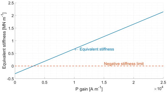
Figure 4.
Relationship between AMBs stiffness and PID proportional gain, showing that a minimum P of 3000 A gain is necessary to overcome the negative stiffness.

Table 2.
AMB control parameters.
To combine the AMB force with the rotor model, a stiffness matrix is created. The negative stiffness of each AMB, , is applied on the x and y degrees of freedom at the AMB node locations. The control contribution, , is applied in the same way, except on the columns corresponding to the appropriate sensor degree of freedom, to account for the non-collocation between sensor and actuator. It measures the displacement at the nodes of the sensors, and applies a force on the nodes of the AMBs. The rest of consists of zeros. The AMB damping matrix is built in the same way, with only the controlled damping placed in the same manner and zeros for the rest. The assumption is made that the AMB action does not have any x/y cross-coupling [25].
3.2. Bending Actuator Control
The active rotor section has an actuator with built in control that allows for quick iterations, such that the resonance vibration peak can be overcome using the smallest possible force. Three main parameters are used in the adaptive control, which are the metric (i.e. displacement at sensors, coil control current, etc.), the tolerance for the metric, which when exceeded will trigger the rotor to slow down and an increase in the control moment, and finally the speed at which the bending moment is adjusted. Figure 5 summarises the adaptive algorithm logic used to adjust the control force. The concept of reducing the speed before proceeding to the adjustment arises from practical considerations, where it is safer to operate the rotor away from the resonance frequency when the adjustment is made, otherwise any small variation around the resonance could be amplified greatly. There is an optimum set of parameters where the correct control force is reached quickly and the rotor speed is not reduced more than necessary, which is a compromise to be found during a future experimental phase.
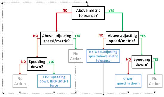
Figure 5.
Bending control loop used by the algorithm to control the rotor speed and the bending moment level.
If the metric is still above the tolerance level while at the rotor adjusting speed, the algorithm exits as it is considered unsafe to increase the bending control. This can be avoided by setting the adjusting speed low enough, or by setting an adjusting vibration level where the algorithm commands the motor to slow down until it reaches a safe vibration level to make the adjustment. The disadvantage to go by vibration level rather than speed, is that the displacement phase may change from positive to negative very quickly at the resonance, risking triggering the adjustment of the force on resonance.
4. Simulated Performance
To combine the rotor model with the AMB levitation, the bending control and the unbalance, the moments and forces must be applied on the corresponding nodes. The control force vector and the unbalance force vector can be added to the left-hand side of the Equation (2). The AMB damping and stiffness are summed with the rotor gyroscopic and stiffness matrices and . The full system from Equation (2) can be re-written as:
To evaluate the displacements for a given unbalance and control force, it is assumed that the trajectories in the x and y axes can be described as a sine and cosine combination of amplitude along the time t and at a rotation frequency as:
In the same way, and can be expressed as
The complex unbalance location vector is used to place the unbalance on node with
Similarly, the complex control location vector places the control moments on nodes and with
The vectors and retain the amplitudes and locations of unbalance and control force, while the angles and are the phase shifts of the forces set, respectively, to 0 and . This complex formulation enables the displacement to be found utilising the Euler formula, by taking the real part of the vector . By differentiating Equation (11), and substituting it along with (12) in Equation (10), the displacements obtained for a given force are:
5. Modal Analysis
Before the response in terms of displacement of the rotor is studied, the mass, gyroscopic, damping and stiffness matrices obtained through the finite element model can be used to carry out a modal analysis of the active rotor system in order to identify the resonant frequencies, mode shapes, and influence of the bearings and rotation speed. The damped natural frequencies are found as the eigenvalues of the state space matrix
The eigenvalue matrix and eigenvector matrix can be found by solving . Then, considering a general complex result , the diagonal of , the damped natural frequencies can be identified as . The real part indicates the stability of each mode, a positive value indicates an unstable mode.
Since the AMBs enable fine tuning of the support stiffness, the influence of the radial stiffness on the eigenvalues is examined. Figure 6 shows the evolution of the first 6 modal eigenvalues versus the AMB equivalent radial stiffness without gyroscopic effects. Two plateaux are visible, representing the free-free and clamped-clamped conditions, with a transition between and N m. Figure 7 shows the case where the gyroscopic effects are included with the rotor rotating at 10,000 RPM. A slight mode splitting between the forward and backward whirl is visible. These results show that the stiffness of N m is located in the transition zone, which allows to adjust the resonance frequencies easily by varying the proportional gain of the controller.
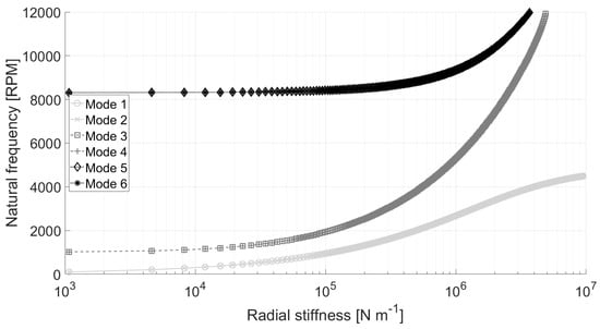
Figure 6.
Active Magnetic Bearing stiffness influence on natural frequencies at 0 RPM.
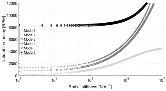
Figure 7.
Active Magnetic Bearing stiffness influence on natural frequencies at 10,000 RPM.
When it comes to the stability of these modes, Figure 8 shows the real parts of the eigenvalues associated with each mode versus the rotating speed, all of them being negative, hence stable.
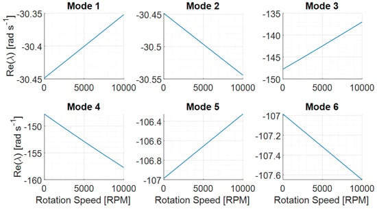
Figure 8.
Stability of the first 6 resonance frequencies over the speed range. Negative real parts indicate stable behaviour. The stiffness and damping are set as described in Table 2.
Figure 9 shows the Campbell diagram, with the natural frequency evolution versus rotating speed. The relatively low mode splitting due to gyroscopic effects is evident. Six intersections between the rotor speed and natural frequencies over the operating range can be noted. The modes for which the natural frequencies decrease with rotating speed are backward whirls, whereas those increasing are forward whirls. Only the latter should be excited by the unbalance. This leaves three resonance frequencies that will be encountered while speeding up, at 2700 RPM, 5300 RPM and 9300 RPM.
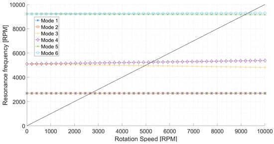
Figure 9.
Campbell diagram of the rotor. The stiffness and damping are set as described in Table 2.
The mode shapes of the forward whirls that will be excited by the unbalance are displayed in Figure 10. Considering that the centre of mass of the rotor is very close to the axial middle position, the second forward whirl mode will not be excited strongly as it has a node of vibration at this location, leaving peaks likely to happen at the first and third forward whirls around 2700 RPM and 9300 RPM.
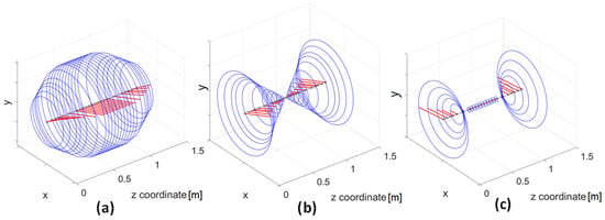
Figure 10.
First 3 forward whirl mode shapes at (a) 2700 RPM, (b) 5300 RPM and (c) 9300 RPM.
6. Control Results
Initially the effect of applying control bending moment on the rotor nodes radial displacement is examined. Figure 11 displays the effect that an increasing symmetrical controlled bending moment has on a rotor with an unbalance of 180 g mm at 2400 RPM.
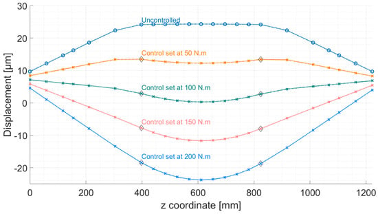
Figure 11.
Rotor radial displacement at 2400 RPM for different control moments and a 180 g mm unbalance.
The uncontrolled deflected shape corresponds with the larger second moment of area of the middle section, almost undeformed compared to the smaller diameter support shafts. The relatively low stiffness of the AMBs is also displayed by the fact that the AMBs nodes are not fixed at zero displacement but are closer to a free-free condition rather than a clamped-clamped condition. Increasing the bending control moment shows that the rotor cannot be straightened perfectly as the two moments cannot counteract the unbalance force. It is, however, possible to optimise the moment in several ways, depending on the rotor application. For example, the average radial displacement of every node the rotor could be minimised, or else the distance of each radial displacement to the average radial displacement, thus ensuring that the rotor is as straight as possible. Another example is if an attachment such as a disk with blades is located at a specific point along the shaft, it is possible to minimise the radial displacement for this particular point in order to maintain the clearance between the blades and the stator, which is a critical parameter for efficiency. The case of the rotor mid-point radial displacement being minimised is used to examine the adaptive algorithm, where the rotor is spun up to 10,000 RPM with the unbalance of 180 g mm. The adjusting speed, where the force will be iteratively increased if the tolerance is exceeded, is set at 2000 RPM while the vibration limit not to be exceeded is set to 15 . The speed increment or decrement at each iteration of the loop is set to 10 RPM and the bending moment increase is 8.5 N m each time the adjusting speed is reached while speeding down. Figure 12 shows the resulting controlled and uncontrolled profiles. The first visible features are the resonance peaks at 2500 RPM and 3000 RPM that exceed the acceptable vibration levels of the uncontrolled run. It is evident that with the algorithm it takes about 5 control moment increases to overcome the first peak, and a further 13 for the second peak. Overall, the amplitude of the vibration radial displacement is reduced from 55 to 30 of variation, or a 45% reduction, allowing the entire rotor to speed up to 10,000 RPM while never exceeding the 15 limit.
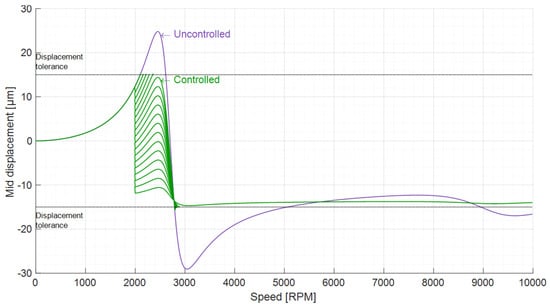
Figure 12.
Adaptive algorithm action on the rotor mid-point radial displacement, with a 15 radial displacement tolerance and 2000 RPM as the adjusting speed.
Figure 13 gives further insights on the algorithm path used to overcome the resonance peaks without exceeding the displacement tolerance, where various parameters can be seen against the iteration number, which represents one loop in the algorithm shown in Figure 5. Here it seen that a control moment of 43 Nm is enough to overcome the first resonance peak, while it needs to be increased to 145 Nm to overcome the second peak. The entire speed range is covered in about 3200 iterations of the algorithm, which can be related to a time via the inertia of the rotor and the maximum torque of the motor used to spin the rotor.
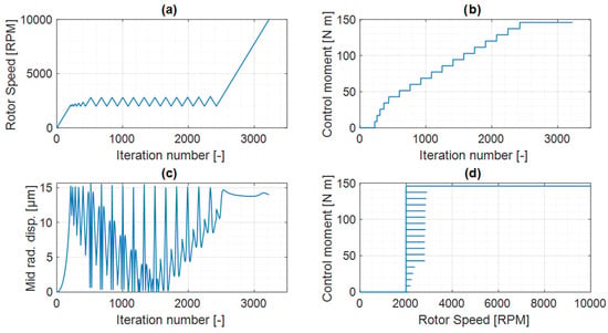
Figure 13.
Path taken by the algorithm to optimise the actuator moment using the adjusting speed approach (a) Rotor speed at each iteration (b) Actuator moment at each iteration (c) Radial displacement at each iteration (d) Actuator moment at each speed.
In order to reduce the number of iterations needed to reach the maximum speed, an approach of slowing down the rotor to a certain level of vibration is tested and displayed on Figure 14. Instead of slowing down to 2000 RPM when the tolerated displacement is exceeded, the rotor is slowed down until the radial displacement is less than 12 (adjusting metric approach). Using this new process, the control manages again to keep the vibrations under 15 while speeding all the way up to 10,000 RPM, and does not pass through the first resonance peak anymore when it tries to overcome the second peak.
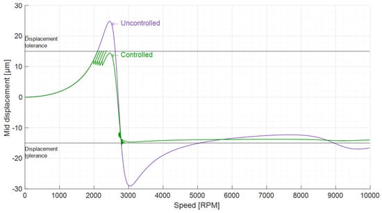
Figure 14.
Adaptive algorithm action on the rotor mid-point radial displacement, with a 15 radial displacement tolerance and a 12 adjusting radial displacement.
Figure 15 shows the main difference between the two approaches, which is that the number of iterations needed to reach the maximum speed is now around 1300 which is 60% less than with the adjusting speed approach, thus cutting the time that the algorithm takes to reach maximum speed. However, the adjustments are made very close to the resonance, which may be problematic in practice.
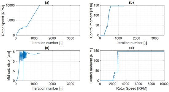
Figure 15.
Path taken by the algorithm to optimise the actuator moment using the adjusting metric approach (a) Rotor speed at each iteration (b) Actuator moment at each iteration (c) Radial displacement at each iteration (d) Actuator moment at each speed.
In summary, application of a counter-bend moment around the rotor section couplings shows that it is possible to straighten the shaft. However, the bending moment required depends on many parameters, including the rotating speed and the proximity to resonant frequencies or critical speeds. The two algorithms described aim at applying the minimum required force to accelerate the rotor to its maximum speed without the vibrations exceeding a threshold level, by reducing the rotor speed and progressively increasing the control force. The rotor speed reduction is the main difference between the two algorithms, with the first method slowing the rotor to a set speed, whereas the second approach reduces the vibrations to a fixed level when the control is applied. The choice of which version of the algorithm to use will be determined by the application. If a constant speed above a resonance frequency is needed and time can be used to safely overcome the resonance, the adjusting speed approach is safer, while if time is of the essence the adjusting metric approach will lead to a faster ramp up to the maximal speed, at the cost of potentially actuating very close to the resonance.
Along with the theoretical modelling and simulations, a prototype is being designed and built, with Figure 16 displaying the preliminary design of disks and flanges used to accommodate the internal actuator system and couple the active section to the passive sections.
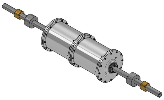
Figure 16.
3D model of the rotor prototype under development.
7. Conclusions
This paper outlines a novel rotor vibration reduction concept combining active magnetic bearings and localised bending control through an active rotor. Each component of the design that has a significant effect on the rotor dynamics is modelled, including the AMBs controller and an adaptive bending control algorithm. Full modal analysis is carried out, predicting the resonance frequencies locations, mode shapes and stability within the operating range, concluding that the main vibration peak appears at 2700 RPM. The artificial bending moments are shown to allow fine control over the shape of the rotor, opening possibilities for strategies aimed at minimising the vibration levels. Using this effect with a G10 mid point balance condition, the control algorithm succeeds in maintaining the rotor radial displacement below a 15 threshold over the entire speed range from 0 to 10,000 RPM, a 45% reduction compared to the original peak vibration level. The simulations also show that depending on the application, the algorithm is flexible in the way it can be implemented in order to minimise certain values or be safer during the control phase around the resonance frequencies. This algorithm and mechanism of control are particularly well suited for rotor applications where the external loading is changing and difficult to predict, for instance to counteract thermal effects or unpredictable environmental disturbances as occurring in transport applications.
Author Contributions
Conceptualization, G.A.F., N.Y.B. and P.S.K.; methodology, G.A.F., N.Y.B. and P.S.K.; software, G.A.F.; validation, G.A.F., N.Y.B. and P.S.K.; writing—original draft preparation, G.A.F.; writing—review and editing, N.Y.B. and P.S.K.; supervision, N.Y.B. and P.S.K.; project administration, P.S.K.; funding acquisition, P.S.K. All authors have read and agreed to the published version of the manuscript.
Funding
This research was funded by EPSRC Future Advanced Metrology Hub, EP/P006930/1 and a University of Bath URS award for Gauthier Fieux’s PhD study.
Informed Consent Statement
Not applicable.
Data Availability Statement
Data available on request.
Conflicts of Interest
The authors declare no conflict of interest.The funders had no role in the design of the study; in the collection, analyses, or interpretation of data; in the writing of the manuscript, or in the decision to publish the results.
References
- Zhou, S.; Shi, J. Active balancing and vibration control of rotating machinery: A survey. Shock Vib. Dig. 2001, 33, 361–371. [Google Scholar] [CrossRef]
- ISO 1940-1: 2003; Mechanical Vibration—Balance Quality Requirements for Rotors in a Constant (Rigid) State—Part 1: Specification and Verification of Balance Tolerances. International Organization for Standardization: Geneva, Switzerland, 2003.
- MacCamhaoil, M. Static and Dynamic Balancing of Rigid Rotors; Bruel and Kjaer: Nærum, Denmark, 2016. [Google Scholar]
- Thearle, E.L. Dynamic Balancing Machine. U.S. Patent 1876524A, 6 September 1932. [Google Scholar]
- Huang, W.Y.; Chao, C.P.; Kang, J.R.; Sung, C.K. The application of ball-type balancers for radial vibration reduction of high-speed optic disk drives. J. Sound Vib. 2002, 250, 415–430. [Google Scholar] [CrossRef]
- Green, K.; Champneys, A.; Friswell, M.; Munoz, A. Investigation of a multi-ball, automatic dynamic balancing mechanism for eccentric rotors. Philos. Trans. R. Soc. A Math. Phys. Eng. Sci. 2008, 366, 705–728. [Google Scholar] [CrossRef]
- Jung, D.; DeSmidt, H. A new hybrid observer based rotor imbalance vibration control via passive autobalancer and active bearing actuation. J. Sound Vib. 2018, 415, 1–24. [Google Scholar] [CrossRef]
- Van de Vegte, J.; Lake, R. Balancing of rotating systems during operation. J. Sound Vib. 1978, 57, 225–235. [Google Scholar] [CrossRef]
- Pardivala, D.N.; Dyer, S.; Bailey, C.D. Design modifications and active balancing on an integrally forged steam turbine rotor to solve serious reliability problems. In Proceedings of the 27th Turbomachinery Symposium, Houston, TX, USA, 20–24 September 1998. [Google Scholar]
- Alauze, C.; Der Hagopian, J.; Gaudiller, L.; Voinis, P. Active balancing of turbomachinery: Application to large shaft lines. JVC/J. Vib. Control 2001, 7, 249–278. [Google Scholar] [CrossRef]
- Jiménez, S.; Keogh, P.; Cole, M. Internal sensing and actuation strategies for smart machine rotors. In Proceedings of the 9th IFToMM International Conference on Rotor Dynamics, Milan, Switzerland, 22–25 September 2014; Springer International Publishing: Cham, Switherland, 2015; Volume 21, pp. 1527–1537. [Google Scholar]
- Przybylowicz, P.M. Near-critical behaviour of a rotating shaft actively stabilised by piezoelectric elements. Syst. Anal. Model. Simul. 2002, 42, 527–537. [Google Scholar] [CrossRef]
- Horst, H.G.; Wolfel, H. Active vibration control of a high speed rotor using PZT patches on the shaft surface. J. Intell. Mater. Syst. Struct. 2004, 15, 721–728. [Google Scholar] [CrossRef]
- Sloetjes, P.; De Boer, A. Vibration reduction and power generation with piezoceramic sheets mounted to a flexible shaft. J. Intell. Mater. Syst. Struct. 2008, 19, 25–34. [Google Scholar] [CrossRef]
- Naebe, M.; Shirvanimoghaddam, K. Functionally graded materials: A review of fabrication and properties. Appl. Mater. Today 2016, 5, 223–245. [Google Scholar] [CrossRef]
- Alexander, P.W.; Brei, D.; Halloran, J.W. DEPP functionally graded piezoceramics via micro-fabrication by co-extrusion. J. Mater. Sci. 2007, 42, 5805–5814. [Google Scholar] [CrossRef]
- Przybyłowicz, P. Stability of actively controlled rotating shaft made of functionally graded material. J. Theor. Appl. Mech. 2005, 43, 609–630. [Google Scholar]
- Rao, D.K.; Roy, T. Vibration analysis of functionally graded rotating shaft system. Procedia Eng. 2016, 144, 775–780. [Google Scholar] [CrossRef]
- Vadiraja, D.; Sahasrabudhe, A. Vibration analysis and optimal control of rotating pre-twisted thin-walled beams using MFC actuators and sensors. Thin-Walled Struct. 2009, 47, 555–567. [Google Scholar] [CrossRef]
- Lusty, C.; Bailey, N.Y.; Keogh, P.S. Control of flexible rotor vibration with flexibly mounted active magnetic bearings. Mech. Mach. Sci. 2019, 62, 65–73. [Google Scholar]
- Der Hagopian, J.; Mahfoud, J. Rotating machine critical speed suppressing by using electromagnetic actuators. In Proceedings of the ASME 2011 Turbo Expo: Turbine Technical Conference and Exposition, Vancouver, BC, Canada, 6–10 June 2011; Volume 6, pp. 315–319. [Google Scholar]
- Provenza, A.J.; Montague, G.T.; Jansen, M.J.; Palazzolo, A.B.; Jansen, R.H. High temperature characterization of a radial magnetic bearing for turbomachinery. J. Eng. Gas Turbines Power 2005, 127, 437–444. [Google Scholar] [CrossRef]
- Circosta, S.; Bonfitto, A.; Lusty, C.; Keogh, P.; Amati, N.; Tonoli, A. Analysis of a shaftless semi-hard magnetic material flywheel on radial hysteresis self-bearing drives. Actuators 2018, 7, 87. [Google Scholar] [CrossRef]
- Dagnaes-Hansen, N.; Santos, I.F. Magnetic bearings for non-static flywheel energy storage systems (FESS). In Proceedings of the 10th International Conference on Rotor Dynamics—IFToMM, Rio de Janeiro, Brazil, 23–27 September 2018; Springer International Publishing: Cham, Switherland, 2019; Volume 60, pp. 116–131. [Google Scholar]
- Bleuler, H.; Cole, M.; Keogh, P.; Larsonneur, R.; Maslen, E.; Nordmann, R.; Okada, Y.; Schweitzer, G.; Traxler, A. Magnetic Bearings: Theory, Design, and Application to Rotating Machinery; Springer: Berlin, Germany, 2009. [Google Scholar]
- ISO 14839-2:2004; Mechanical Vibration—Vibration of Rotating Machinery Rquipped with Active Magnetic Bearings—Part 2: Evaluation of Vibration. International Organization for Standardization: Geneva, Switzerland, 2004.
- Keogh, P.S. Contact dynamic phenomena in rotating machines: Active/passive considerations. Mech. Syst. Signal Process. 2012, 29, 19–33. [Google Scholar] [CrossRef][Green Version]
- Li, P.; Sahinkaya, M.N.; Keogh, P. Active recovery of contact-free levitation in magnetic bearing systems. Proc. ASME Des. Eng. Tech. Conf. 2012, 1, 673–680. [Google Scholar]
- Defoy, B.; Alban, T.; Mahfoud, J. Experimental assessment of a new fuzzy controller applied to a flexible rotor supported by active magnetic bearings. J. Vib. Acoust. Trans. ASME 2014, 136, 051006. [Google Scholar] [CrossRef]
- Nguyen, N.P.; Mung, N.X.; Thanh, H.L.N.N.; Huynh, T.T.; Lam, N.T.; Hong, S.K. Adaptive sliding mode control for attitude and altitude system of a quadcopter uav via neural network. IEEE Access 2021, 9, 40076–40085. [Google Scholar] [CrossRef]
- Gautam, D.; Ha, C. Control of a quadrotor using a smart self-tuning fuzzy PID controller. Int. J. Adv. Robot. Syst. 2013, 10, 380. [Google Scholar] [CrossRef]
- Lusty, C.; Keogh, P. Active vibration control of a flexible rotor by flexibly mounted internal-stator magnetic actuators. IEEE/ASME Trans. Mechatron. 2018, 23, 2870–2880. [Google Scholar] [CrossRef]
- Maslen, E.; Hermann, P.; Scott, M.; Humphris, R. Practical limits to the performance of magnetic bearings: Peak force, slew rate, and displacement sensitivity. J. Tribol. 1989, 111, 331–336. [Google Scholar] [CrossRef]
- Lalanne, M.; Ferraris, G. Rotordynamics Prediction in Engineering, 2nd ed.; John Wiley: Hoboken, NJ, USA, 1990. [Google Scholar]
Publisher’s Note: MDPI stays neutral with regard to jurisdictional claims in published maps and institutional affiliations. |
© 2022 by the authors. Licensee MDPI, Basel, Switzerland. This article is an open access article distributed under the terms and conditions of the Creative Commons Attribution (CC BY) license (https://creativecommons.org/licenses/by/4.0/).