Abstract
Flywheels are used for peak shaving or load smoothing to generate a higher efficiency and a more stable power supply. Therefore, this paper investigates highly integrated outer rotor flywheels levitated by active magnetic bearings (AMB). Due to the highly gyroscopic behavior and the diametrical enlargement under rotation, the system behavior changes with the speed, leading to a significant decrease in the maximum force and maximum force slew rate of the AMB. Thus, the speed range in which a decentralized feedback control stabilizes the system is reduced. In the literature, there are numerous approaches for coping with gyroscopic behavior. However, there are far fewer investigations for explicit consideration of the change in the air gap in the control structure. Therefore, the goal of this work is to find a control strategy to reduce the effect of the gyroscopic behavior as well as the change of the air gap. The authors propose a control strategy combining a cross feedback control with a decentralized variable feedback control. With this combination, the drawbacks of the previously described effects are compensated, leading to a higher operating range of the system and a reduced utilization of the amplifier without overcompensation at lower rotational speeds.
1. Introduction
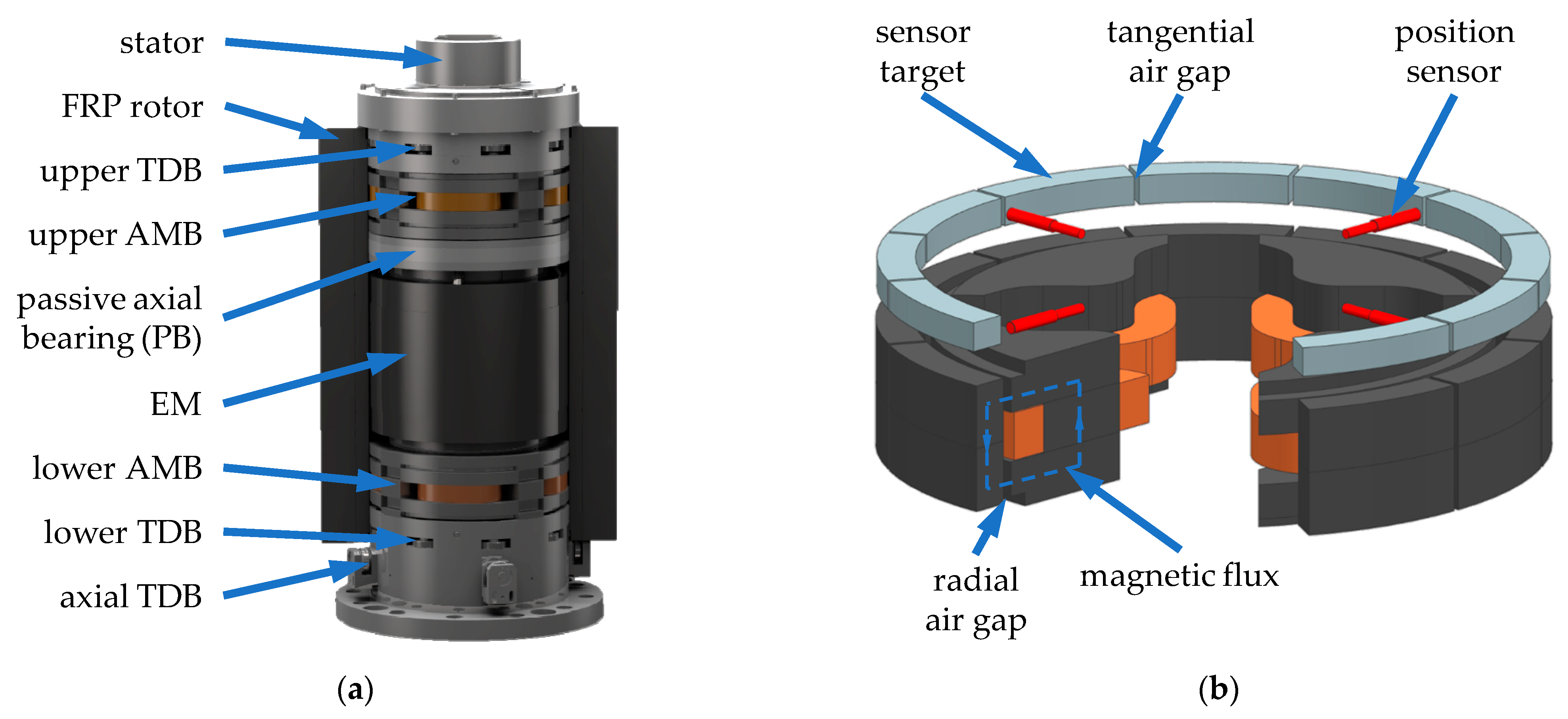
In the course of the energy transition, conventional power sources are replaced by renewable energies. Therefore, flywheels gain more and more relevance since they can be used for peak shaving or load smoothing to generate a more efficient and stable power supply (e.g., [1]). The Technical University of Darmstadt is investigating a special outer-rotor-type flywheel. Three prototypes have been built and tested [2,3,4]. In these systems, a hollow cylinder made of fiber-reinforced plastic (FRP) spins around a fixed stator at high rotational speeds. In comparison to other flywheels, this design is characterized by a high gravimetric energy density resulting from a high polar moment. For the energy conversion, a permanently excited synchronous electric machine (EM) is used. Figure 1 shows the CAD model of the second prototype ETA-290 and of the radial active magnetic bearings (AMBs) of the system.
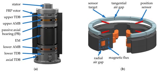
Figure 1.
(a) Partial section view of the ETA-290 without the containment; (b) radial AMB with sensor plane and air gaps [2].
The system is levitated by an axial permanent magnetic bearing (PM) and two radial AMBs. To reduce drag losses, the system operates in vacuum. Mechanical touch-down bearings (TDBs) are used to protect the system in case of an overload or failure of the AMBs. Due to the high diameter in the TDBs and the high rotational speeds, conventional TDBs are not suited for the system. Therefore, the planetary TDB design is applied. In [5,6], the planetary TDB is described in more detail, and the performance is analyzed for this and a similar test rig. Due to the high rotational speeds and radii, the material of the rotor has to withstand high centrifugal forces or likewise high stresses. As a result, from these stresses and the material elasticity, the rotor enlarges under rotation. This enlargement is unintentional but had to be considered during the design phase. Therefore, all rotating parts of the active components, which are integrated on the inner circumference of the rotor, are segmented in the tangential direction (see Figure 1). The active components such as soft magnetic composites (SMCs) do not offer a high tensile strength. In a closed ring, the radial acting centrifugal force is redistributed in the tangential direction, causing high stresses that lead to cracks in the ring. Thus, a nondefined segmentation with possible loose fragments would occur. With a predefined segmentation, no failure with loose fragments occurs during speedup.
The segmentation of the sensor target leads to tangential air gaps which increase with the enlargement of the rotor (see Figure 1). Those air gaps are misinterpreted by the position sensors as a change of the rotor position leading to unnecessary activities of the AMBs and thus to a high amplifier load, especially, if the controller of the AMBs is set to high damping. The damping in the controller is needed for system stability at high rotational speeds due to the highly gyroscopic behavior and diametral enlargement. This will be discussed further in Section 3. The topic of a high damping for system stability is closely related to the phenomenon of chatter in machining processes, where AMBs or piezoelectric actuators are used to suppress the chattering [7]. With the control of the active components, additional damping can be introduced in the system, thus reducing the chattering significantly as shown in [8,9,10,11]. Control structures used for this purpose are model predictive control [11] and -synthesis [9] in combination with gain scheduling [8].
For AMB systems in general, there are a variety of control strategies applicable. However, the common control structure for AMBs is a decentralized feedback controller [12,13]. Due to the diametral enlargement under rotation, the behavior of the system, especially of the magnetic bearings, changes, which may lead to instability of the closed loop. The stability is further influenced by the gyroscopic behavior of the rotor. One example of the relevance of the consideration of the system stability of highly gyroscopic outer rotor systems is given in [14], where a flywheel system with AMBs and a decentralized feedback control became unstable at high rotational speeds. Therefore, as mentioned by [15,16], the highly gyroscopic behavior of flywheel rotors should be considered during controller design. In the literature, different approaches are given for tackling the challenge. In some publications, the gyroscopic behavior is dealt with explicitly [17,18,19,20,21,22,23]; in others, it is treated as an uncertainty [12,24].
The diametral enlargement of the rotor is less investigated in literature than the gyroscopic coupling. The reason for this is that it only becomes relevant for high diameters with high rotational speeds. For most systems, the thermal growth is larger than the enlargement due to rotation (e.g., [25]). A further reason is that the drawbacks of the enlargement for outer rotor systems which are analyzed in Section 4 do not apply for inner rotor systems, which are far more common. Most literature covering a varying air gap considers the change in the air gap as uncertainty for the controller design [12,26]. In [27], a change in the magnetic air gap occurs due to a special design of the system. Decentralized feedback in combination with a neuronal network is used to control the system.
One approach to consider the uncertainty due to the changing air gap and the gyroscopic behavior in a model-based controller design is to create various models of the system at different speeds. These models can subsequently be used to tune the parameters of a controller with a predefined structure to stabilize all variations of the system. A technique for tuning controllers for various linear systems simultaneously is described in [28]. However, if the changes in the system are too great, a robustly stabilizing parameter set might not be found. In general, considering varying parameters such as the changing air gap or the gyroscopic behavior as uncertainties is a feasible approach for small uncertainties, as in [12], where the uncertainty of 25% is considered. However, if the uncertainties become large, such an approach leads to very conservative controllers or is even not able to find a suitable controller [12,24,26]. For the investigated systems, the air gap more than doubles between standstill and the maximum speed. Hence, the first objective of the paper is to analyze the consequences of these effects for the AMB control for an outer rotor system. Afterward, the goal is to find solutions for the shortcomings resulting from the rotor enlargement and the gyroscopic coupling. As a solution, the authors present a controller combining two control strategies. Its functionality is investigated based on the simulation model even in the case of uncertainties.
2. Materials and Methods
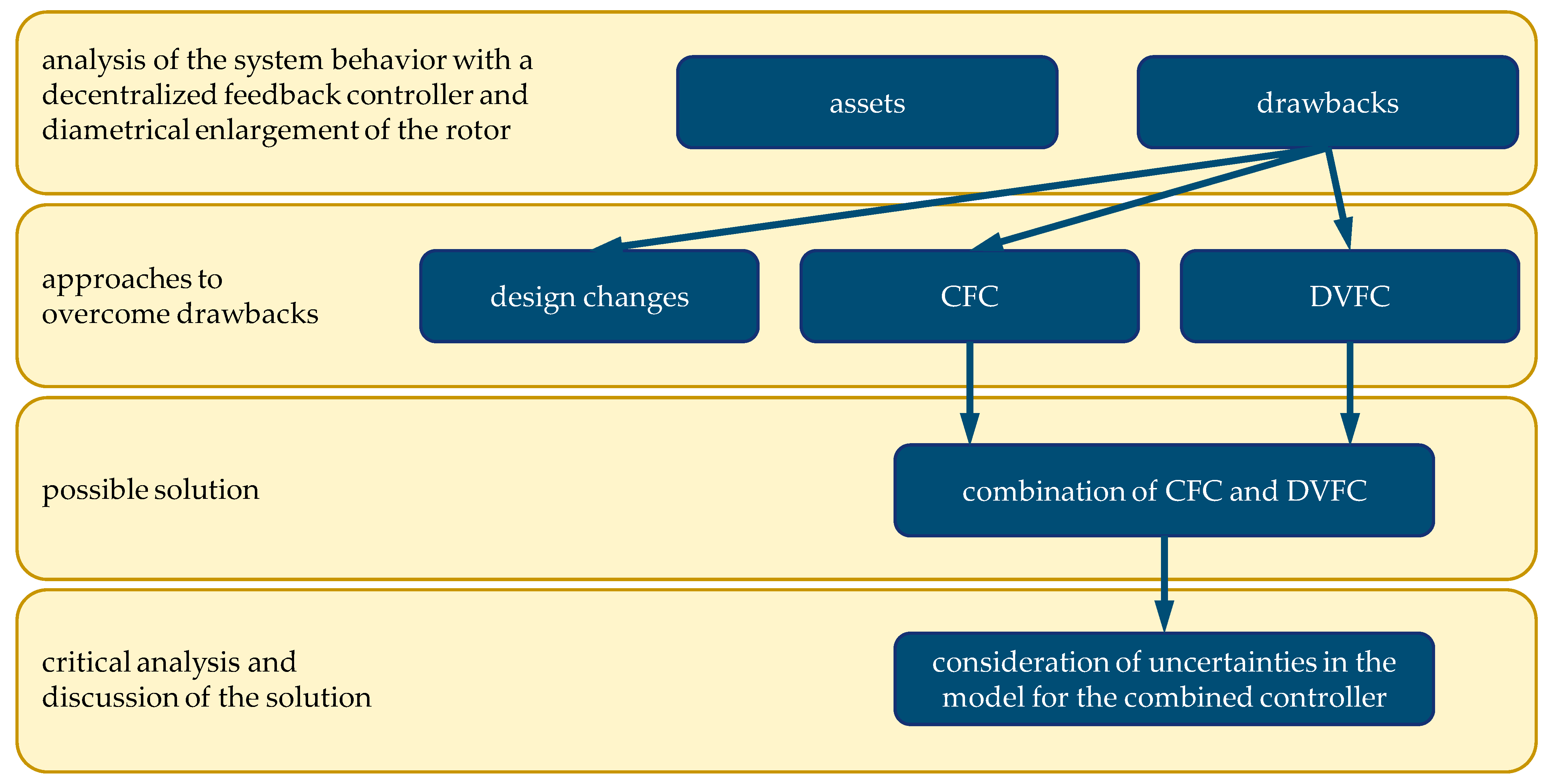
For the following investigation, the method shown in Figure 2 is used. The starting point is a highly gyroscopic rotor in AMBs which enlarges under rotation. Due to the outer rotor design, the air gap of the AMBs rises with the rotational speed, in the discussed system from up to . This leads to a significant decrease in the maximum force and maximum force slew rate of the AMBs. Thus, the system dynamics become speed-dependent. Before dealing with the effects of the diametrical rotor growth on the rotor dynamics, the main components of the model and the dependencies among them are described in Section 3. With the explained relationships of Section 3, the benefits and drawbacks of the diametral enlargement are outlined in Section 4. In Section 5, design changes as well as new controller strategies are discussed. The investigated control strategies are the cross feedback controller (CFC) introduced by [18] and the decentralized variable feedback controller (DVFC). In Section 6, the combination of the introduced DVFC controller with the CFC is shown, which proves to be a suitable solution to deal with the gyroscopic behavior and the rotor enlargement. At the end of the section, the influence of uncertainties in the parameters used for the control design is analyzed. The conclusion of the investigation is given in Section 7.
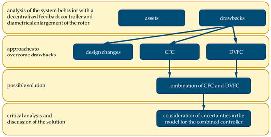
Figure 2.
Method used for the investigation of the control of gyroscopic rotors with diametral enlargement.
3. Analytical Model of the System
To analyze the system behavior a suitable comprehensive model is derived. An overview is shown in Figure 3. The main components of the model, i.e., the AMB, the amplifier, the rotor and the controller, are described in more detail below. Since the electromechanical system is complex, only significant dependencies will be outlined. For more detail see [29,30,31]. The Section ends with a short outline of the whole system model implemented in MATLAB and Simulink.

Figure 3.
Overview of the derived model.
3.1. Active Magnetic Bearing (AMB)
Each AMB consists of four homopolar actuators. A pair of two counteracting actuators is driven in a so-called differential mode [29]. The two counteracting magnets allow generating bidirectional forces, whereas a constant current , also referred to as a bias current, is used for premagnetization to linearize the force–current relation. In Equation (1), an approximation for the resulting AMB force is given, neglecting the influence of the material [29]. The approximation is valid for small deflections of the rotor x compared to the nominal air gap s and small control currents i compared to .
In Equation (1) is the force–current factor and is the force–displacement factor. is the magnetic permeability in vacuum. Since the force–displacement factor is negative, the AMB shows a negative stiffness resulting in an unstable behavior without adequate control. Due to the outer rotor design and the diametric enlargement of the rotor, the air gap s increases with an increase in rotational speed. This varying air gap is estimated as a polynomial function of second order as shown in Equation (2), which is derived from the quadratic dependency on the rational speed shown in [32].
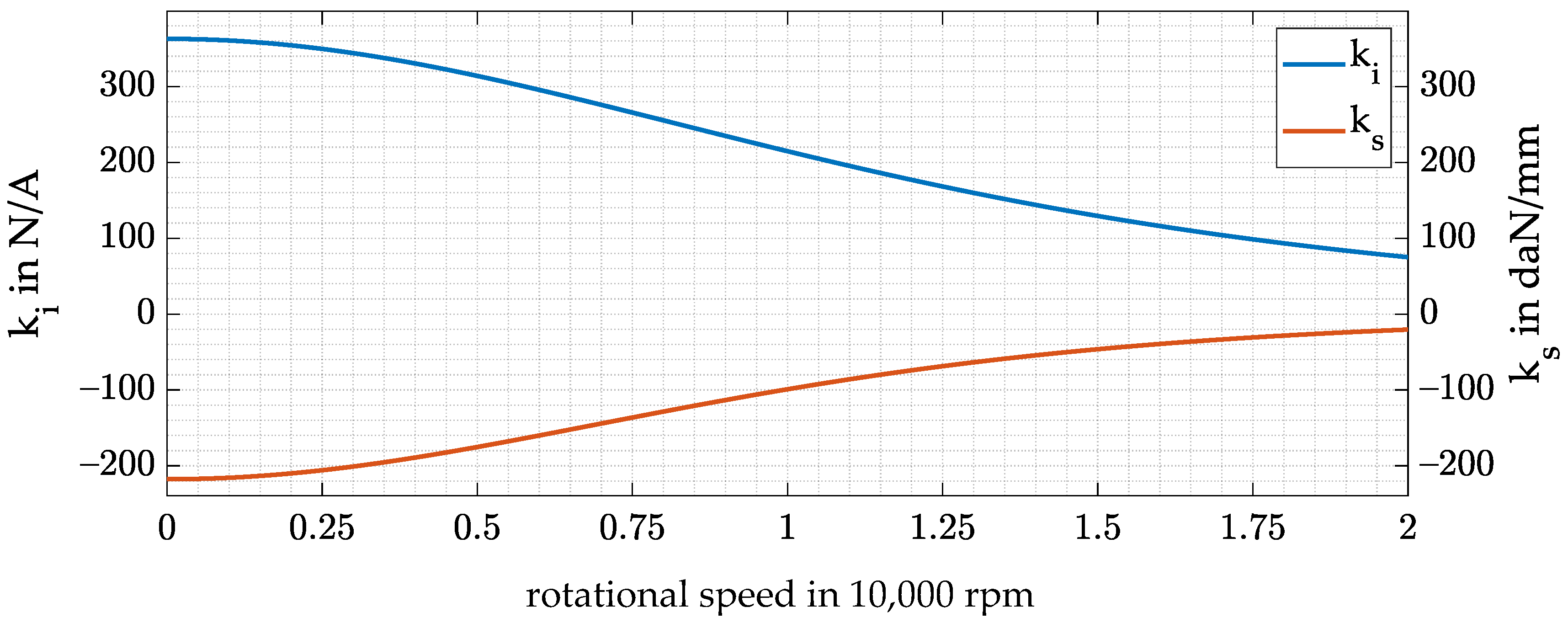
Here, is the initial air gap of the system and is the rotational speed. The coefficients and are determined by a finite element simulation of the rotor. As a result of Equations (1) and (2), the force–current and force–displacement factors also become speed-dependent, as shown in Figure 4.
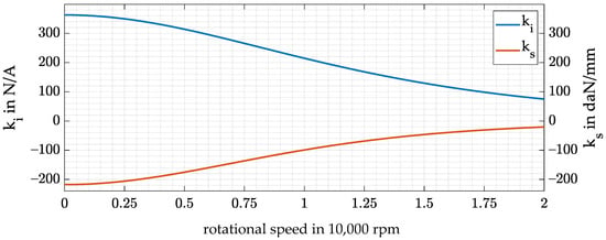
Figure 4.
and against the rotational speed.
3.2. Amplifier
The dynamics of the AMB are determined by the dynamics of the amplifier connected to the electromagnets of the bearing itself. To understand the dynamic behavior of the actuator, the electric part of the electromagnet has to be included as well since the resistance R and inductivity L of its coil represent a static and dynamic load to the amplifier. The voltage induced by the motion of the rotor is neglected, as are eddy current effects. In [33], it is shown that the eddy currents can be neglected in the model for layered core materials for frequencies below 1000 Hz. In [34], it is shown that eddy currents have an even lesser influence for SMCs. In addition, [35] showed a low influence of eddy currents with SMC materials. Therefore, the electric part of the electromagnet is described in Equation (3) [29], where is the resulting load voltage of the amplifier.
Each coil of the electromagnets is driven by one amplifier so that the inductive load follows Equation (4).
is the area actuator face at the coil. The amplifier itself can be seen as a static gain. This results in a proportional relation between the output voltage of the position controller , i.e., the requested current and the amplifier output voltage shown in Equation (5).
The dynamics of the actuator can be expressed by the cutoff frequency of the R-L circuit as shown in Equation (6), which describes up to which frequency the current in the coil follows the commanded current with only a slight shift in phase or magnitude.
To increase this cutoff frequency and therefore the dynamics of the AMB, a PI current controller can be attached to the actuator. The proportional factor of the PI controller is expressed with P, while the integrating constant is expressed with I. Defining leads in combination with the R-L circuit to the relation in Equation (7).
Unfortunately, the given relation for the cutoff frequency only holds for small current commands since the load voltage of the amplifier and its maximum current are limited and therefore also the maximum power of the amplifier is limited. This circumstance leads to a limited driving range of the actuator [36]. Without any knowledge of the premagnetization scheme, the driving range is bounded by the frequency-dependent maximum current amplitude Îmax in the coil windings resulting from the maximum load voltage amplitude of the amplifier Ûmax as shown in Equation (8) [29].
Due to the desired differential driving mode for the premagnetization, a constant current has to be generated by the amplifier as well. The maximum current amplitude for the control current can therefore not exceed , resulting in another upper boundary. The frequency where Îmax equals is the saturation frequency of the amplifier [36]. Furthermore, the maximum load voltage amplitude Ûmax decreases with increasing copper resistance of the coil windings and increasing premagnetization current shown in Equation (9).
This results in a decreasing maximum current amplitude Îmax(ω).
Due to the diametric enlargement of the rotor and the subsequent increase in the air gap, L also becomes speed-dependent. The inductivity decreases with increasing rotational speed of the rotor since (see Equation (4)). As a result, the cutoff frequency and the driving range of the actuator also increase, as shown in Equation (10).
Unfortunately, this positive effect does not hold for the maximum force generated by the AMB since it decreases with increasing air gap due to the proportionality shown in Equation (11).
For frequencies below , the following equation holds:
3.3. Rotor
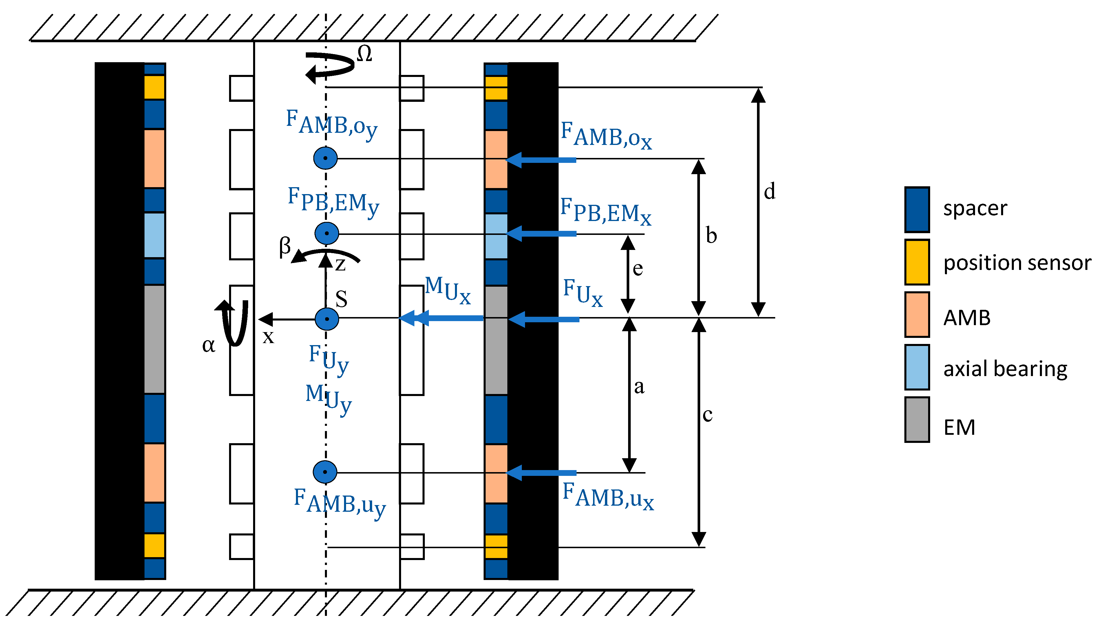
The mechanical part of the system consists of a rotor. To express its behavior, the linearized equation of motion must be derived. Since the first bending eigenfrequency is far higher than the rotating speed of the rotor, the rotor can be described as a rigid rotor [4]. The same applies to the rotor as well. It is rigid, and therefore the stator is neglected in the modeling. According to [29], Equation (13) holds for a rigid rotor supported by AMBs in differential driving mode considering the configuration and definition of variables of Figure 5. The variables used in Equation (13) are explained in detail in the following:
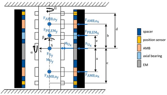
Figure 5.
Configuration of the flywheel.
The mass matrix contains the mass of the rotor and its moments of inertia around the x- and y-axes. The gyroscopic matrix consists of the polar moment of inertia as well as the rotation speed which leads to a coupling of the tilting angles and . The vector contains the center of mass displacements and and the tilting angles.
Furthermore, the equation of motion consists of the negative stiffness matrix of the AMB transformed into center of gravity (COG) coordinates , which is calculated according to Equation (15).
On the right-hand side of the equation of motion, one can find the controllable force of the AMB expressed by the input matrix of the magnetic bearing forces as well as the force–current matrix containing the force–current factors of each AMB and the control current in each planar direction x and y:
Furthermore, Equation (13) consists of the radial force of the negative stiffness of the axial bearing and the electric machine , the input matrix for the negative stiffness forces and the harmonic excitation due to rotor unbalance .
Finally, the output equation consists of the sensor matrix and the measured displacements y of the rotor in each sensor plane and each planar direction x and y:
3.4. Position Control
A common control strategy for a rigid rotor attached in AMBs is a decentralized feedback control (DFC) [29,37]. The closed-loop equation of motion enhanced with such a PD feedback control law independent for each bearing in both directions can thus be determined as
with the diagonal matrices of the feedback gains and .
To achieve closed-loop stability, the so-called stiffness matrix must compensate the negative bearing stiffness as well as the negative radial stiffness caused by the passive axial magnetic bearing and EM. Furthermore, active damping must be provided by the damping matrix to achieve an asymptotically stable behavior. For the presented system, an eigenfrequency of the stator is at 4 Hz. Therefore, the proportional feedback gain , and consequently the resulting stiffness of the controlled AMB, is chosen in such a way that the lowest eigenfrequency of the controlled system is above 5 Hz. Thus, the stator eigenfrequency is not excited by the AMB.
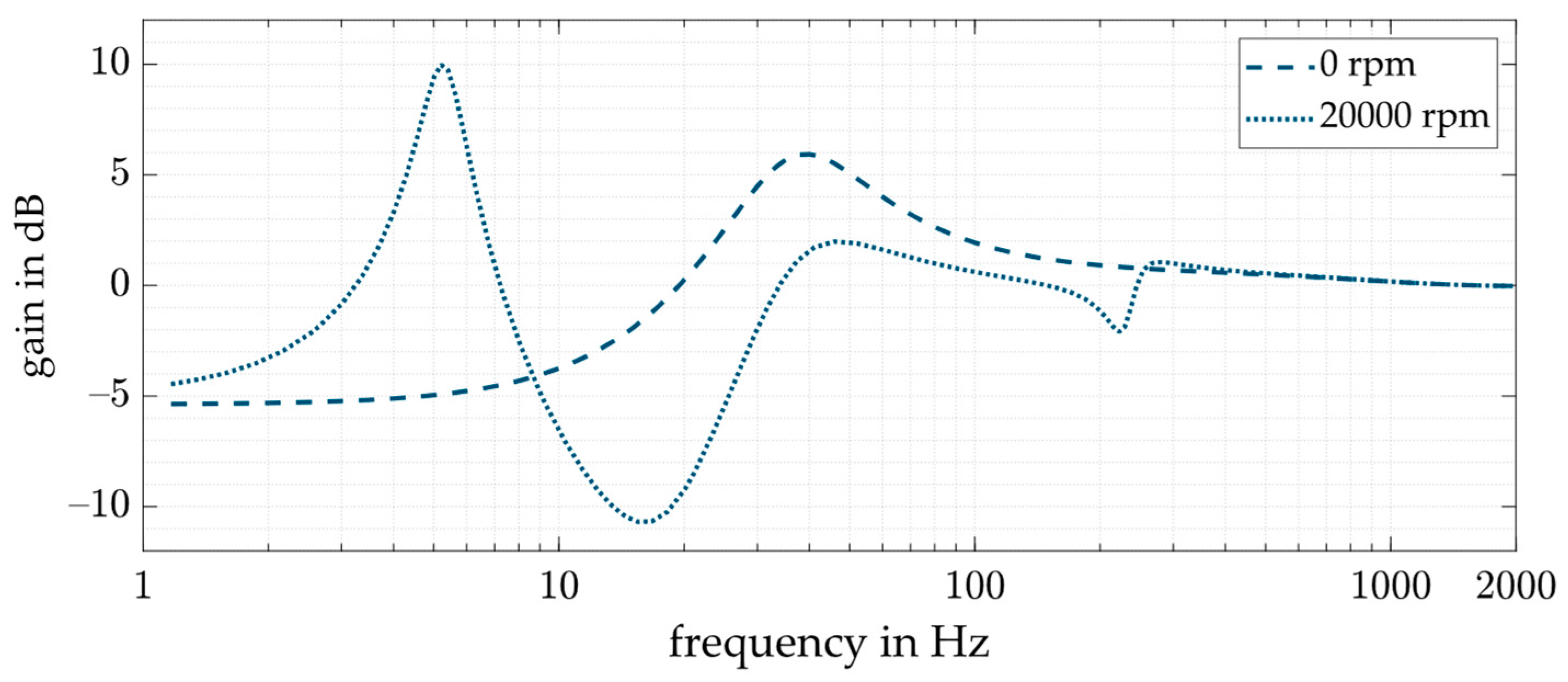
The differential feedback gain is established by the means of ISO 14839-3 to limit the peak gain of the output sensitivity function of the system. Depending on the desired application, ISO 14839-3 has different peak sensitivity values. For newly commissioned machines, a maximum value of 9.5 dB is desired. However, the range acceptable for machines with long-term operation is between 9.5 and 12 dB. Therefore, for the controller design, the upper limit of the sensitivity function gain is set to 10 dB at each driven rotational speed. Figure 6 shows the gain of the sensitivity function for the controlled system with a decentralized PD control for the system without enlargement. For the maximum considered rotational speed of 20,000 rpm, the gain of the sensitivity function has a peak at around 5.2 Hz with the height of the maximum allowed value of 10 dB. According to ISO 14839-3, the output sensitivity function should express the stability margin to specific uncertainties in a general rotor AMB system. This does not hold for every rotor AMB system, as [38] pointed out; however, it is thus used here based on simple implementation and standardization.
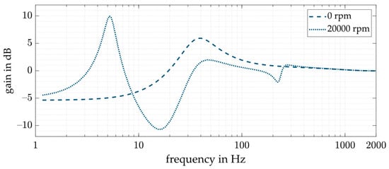
Figure 6.
Sensitivity function for the system with a decentralized PD control for standstill and 20,000 rpm.
The behavior of the AMB in one direction using decentralized PD control can be approximated as a mechanical spring/damper with the stiffness and the damping . In a system with diametric enlargement, and are speed-dependent; hence, the stiffness and damping of the controlled AMB become speed-dependent as well. Equation (20) shows the proportionality of the AMB stiffness and damping to the air gap.
3.5. Model of the Electromechanical System
The previously discussed components of the flywheel were consolidated into a linear model implemented in MATLAB. Since a digital control is utilized (position control of the rotor and current control of the amplifier), time delays for calculation, AD/DA conversion and transport delays are considered. The total time delay is approximated to 1.5 with . The sampling frequency is given as 20 kHz. Since time delays are nonlinear, a Padé approximant of third order is used as an approximation. Furthermore, the system must be equipped with appropriate antialiasing filters, in this case, a low-pass filter of second order with a cutoff frequency of 2 kHz. To account for the limitations of the maximum load voltage and current of the amplifier as well as the discretization due to digitization, a nonlinear time-domain model in Simulink was also derived.
4. Benefits and Drawbacks of Diametral Enlargement of the Rotor and Their Bypassing
The goal of the research is to study the influences of diametral enlargement on the overall electromechanical system, to identify possible drawbacks and, if possible, to circumvent them. Since the influences on the components of the system are already presented in Section 3, the associated benefits and drawbacks of the diametral enlargement will be specified subsequently.
Drawbacks arising with an increasing air gap s(Ω) are as follows:
- Larger electromagnets, hence, an increased number of windings n, are required to generate the same maximum force Fmax;
- Higher copper losses/increasing resistance R of the coil windings due to increased number of windings n;
- Decreasing maximum amplitude of force max (ω) for ω > ωsat (see Equation (11)).
- Benefits of an increasing air gap s(Ω) include the following:
- Increasing driving range of the actuator ωsat (see Equation (10)).
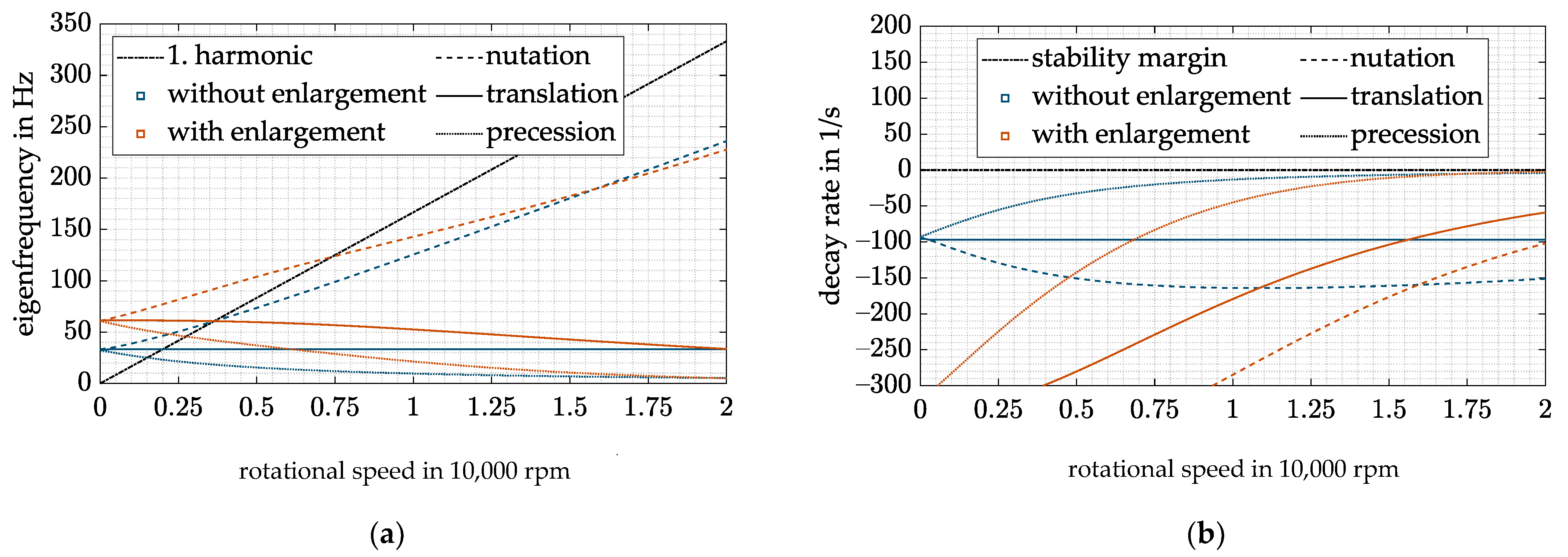
Besides these influences on the components, another drawback arises when dealing with the complete system, which can easily be seen by comparing the Campbell diagram (see Figure 7a) and the decay rate (see Figure 7b) of the system with ( and without ( an increasing air gap s.
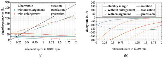
Figure 7.
(a) Campbell diagram with DFC; (b) decay rate with DFC.
Due to the high inertia of the rotor around its rotation axis, the gyroscopic effect forces the precession eigenfrequency to drop significantly with increasing rotational speed. Thus, to keep all eigenfrequencies above 5 Hz as pointed out in Section 3.4, the stiffness of the AMB has to be equal with and without diametral enlargement at the maximum rotation speed. Since the stiffness of the AMB increases with decreasing air gap (see Equation (20)), the eigenfrequencies of the rigid-body modes increase with dropping rotational speed. Unfortunately, this circumstance decreases the operating range of the flywheel as the critical speeds shift toward higher rotation speeds (see Figure 7a). Furthermore, a higher amplifier power is necessary when passing through the resonances at higher rotational speeds.
Another problem of the DFC control can be shown with the decay rate (see Figure 7b). To fulfill the specification of ISO 14839-3 in the entire operation range, has to compensate the decrease in the natural damping of the precession mode. As a result of the enlargement, this leads to very high damping, hence, an overcompensation, at low speeds. A resulting problem at low speeds is that a high leads to a high control activity of the AMB resulting from the measurement errors caused by the tangential air gaps mentioned in Section 1, leading to a high amplifier load. Hence, a compensation of the diametral enlargement of the rotor is needed.
5. Approaches to Deal with the Gyroscopic Behavior and the Rotor Enlargement
There are different approaches to overcome the problem of a decreased maximum force and maximum force slew rate. Firstly, it is investigated if it is possible to change the design to overcome the problems. Afterward, two control strategies are investigated to deal with the highly gyroscopic behavior and the rotor enlargement.
5.1. Design Changes
Since the maximum force to be generated by the magnetic bearing does not depend on the diametral enlargement of the rotor but on the unbalance forces and other possible excitations, this requirement always has to be fulfilled. This means that the number of coil windings must increase with an increase in the air gap. Thus, the power consumption also increases as the resistance rises with the number of coil windings , which cannot be circumvented without adjusting the bias current or changing the linearization mode.
Nearly the same holds for the maximum amplitude of forces above a certain frequency given by the saturation frequency of the amplifier . The force amplitude in this case does only depend on the maximum power of the amplifier. Thus, to generate the same maximum amplitude up to a certain frequency in case of an increasing air gap, the power of the amplifier must increase in the same manner.
The remaining drawback, the decrease in operating range and the overcompensation at lower rotational speeds, can be circumvented by miscellaneous procedures:
The most obvious procedure is to reduce the relative change of the air gap. To do so, only the initial air gap must be increased since the absolute increase in remains constant. Consequently, the magnetic bearing factors and vary less, leading to a reduced stiffness and damping at low operating speeds. Thus, the eigenfrequencies of the rigid-body modes decrease and the unbalance-induced resonance frequencies shift towards lower rotation speeds as desired. Unfortunately, the increased initial air gap is again connected with the previously discussed drawbacks and cannot be seen as a satisfying solution.
5.2. Cross Feedback Controller (CFC)
Another possible solution is to reduce the gyroscopic-induced split-up of the conical eigenfrequencies. Thus, the proportional feedback gain P could be reduced, yielding a reduction in all rigid-body eigenfrequencies. Furthermore, the resonance frequency of the nutation would drop significantly as the nutation would no longer asymptotically tend to (see [31]). Reducing the gyroscopic cross-coupling can be achieved by a cross feedback control (CFC) introduced by [18]. The closed-loop equation of motion enhanced with such a control law can be determined as
with the following compensation matrix:
Taking a closer look at
the constant should match for a complete compensation of the gyroscopic cross-coupling (). Unfortunately, this equality cannot be achieved due to the speed dependency of the force–current factor due to the rotor enlargement resulting in a nonlinear speed-dependent compensation term , which is not the case [18] where the control structure is proposed. Thus, overcompensation of the gyroscopic cross-coupling can take place under certain rotation speeds.
If the maximum value of is substituted into Equation (22) for and time delays are considered through an attenuation factor as proposed by [18], the gyroscopic cross-coupling is only compensated at low rotor speeds. Thus, no overcompensation can take place and the system remains stable. However, the described possible solution is able to shift the critical speeds towards lower rotation speeds (see Figure 8a); thus, the operating range is increased. This is consistent with the literature, where the same approach was used to increase the system stability of a flywheel [16]. However, the achieved operating range of the flywheel still does not match the operating range in case of no diametral enlargement. Comparing the decay rates of Figure 7b and Figure 8b, one can see that the overcompensation is still present at low speeds.
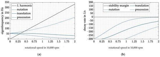
Figure 8.
(a) Campbell diagram with CFC and ; (b) decay rate with CFC and .
Both described procedures to circumvent the decrease in operating range and overcompensation at low speeds address the impact of diametral enlargement. Neither of them tackles the root cause of the problem. The change of and , which is shown in Figure 4, is not compensated by the control structure. To do so, the variation of the speed-dependent magnetic bearing factors and must be introduced into the control law. This could either be done by switching between different controllers with discrete feedback gains according to the rotor speed as in [39,40] or by a single controller with continuously varying feedback gains [8,23]. The latter design was chosen and will be discussed in the subsequent section.
5.3. Decentralized Variable Feedback Control (DVFC)
The diametral enlargement of the rotor reflects in an increasing air gap with rising rotational speed which again results in decreasing factors and , as shown in Figure 4. In presence of a decentralized PD feedback control, this circumstance yields a speed-dependent stiffness and damping of the AMB, as already pointed out in Section 3.4. Equation (24) shows again the calculation of stiffness and damping of the AMB.
For the condition that and equal and , respectively, the resulting stiffness and damping of the AMB are shown in Equation (25).
The stiffness and damping of the AMB are no longer speed-dependent and are now equal to the desired and . Nevertheless, they are still chosen like and in Section 3.4, i.e., keeping all rigid-body eigenfrequencies above 5 Hz and the peak amplitude of the output sensitivity function of the system below 10 dB.
In order to fulfill the desired equality between and as well as and , and have to be known. Since the estimates given in Equations (1) and (2) hold, only the rotational speed has to be known.
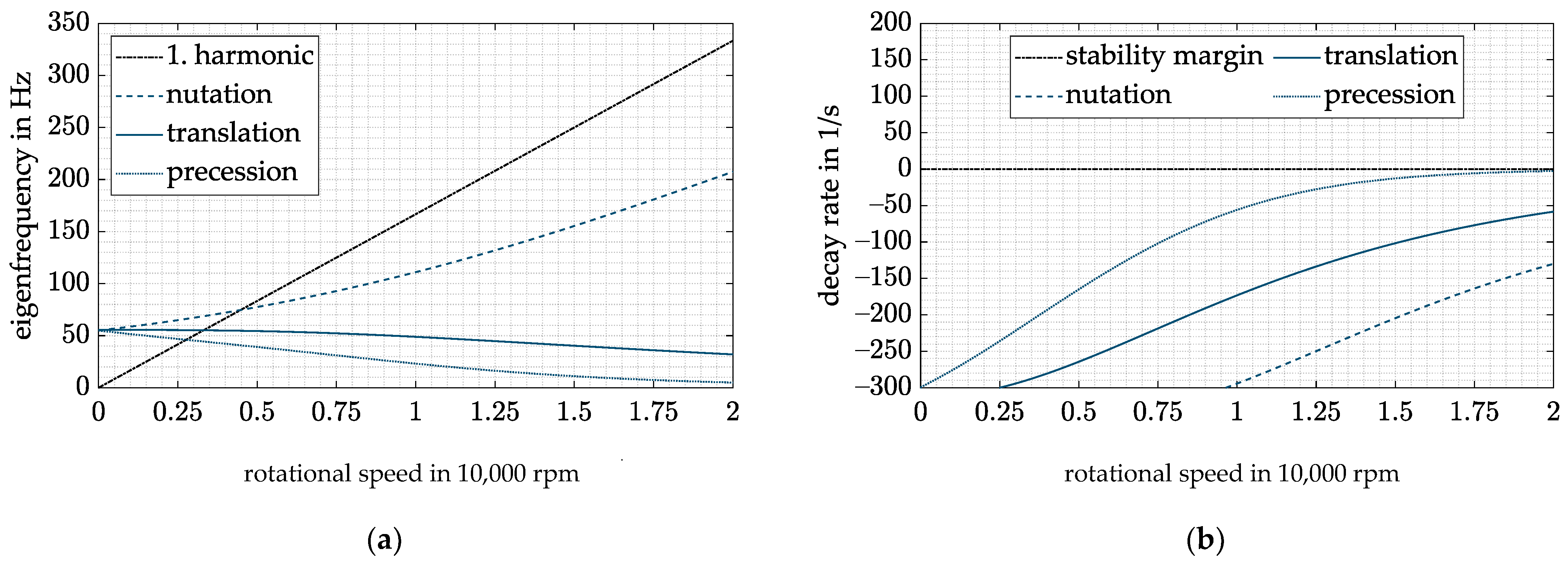
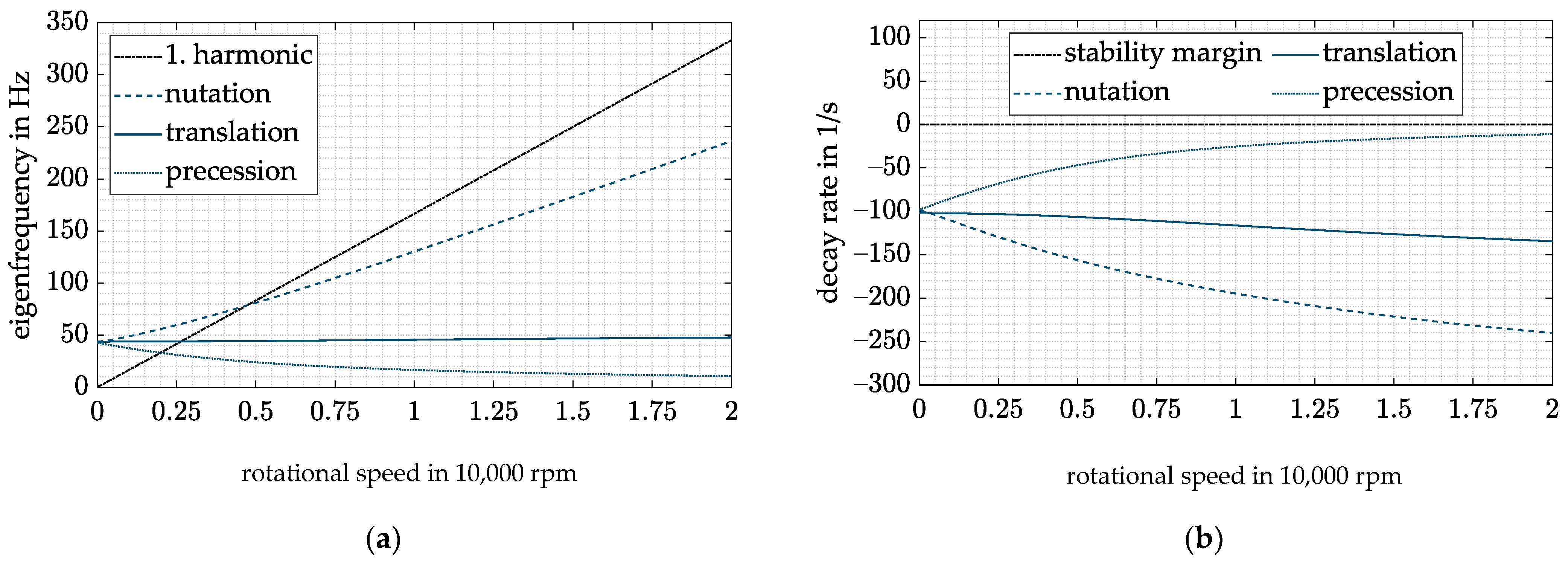
If the considered system is equipped with such a control strategy and the considered assumptions apply without any uncertainties, the behavior in Figure 9 is true. The system equipped with the DVFC has the same rigid-body eigenfrequencies as the system with a standard DFC without diametral enlargement (see Figure 7). Thus, the drawback of a decreasing operating range can be circumvented. Nevertheless, the decay rates of the rigid-body modes and therefore their damping values are lower than those of the standard DFC design without diametral enlargement. The decay rate of the critical precession motion at maximum rotational speed remains the same.
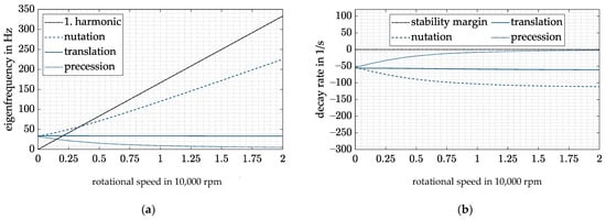
Figure 9.
(a) Campbell diagram with DVFC; (b) decay rate with DVFC.
In contrast to the standard DFC, the setup of the control law of the presented new DVFC involves a calculation of the air gap (see Equation (27)) in order to fulfill the desired identity between and as well as and . The accuracy of this identity depends on the uncertainties of the initial air gap , the coefficients and from the FE simulation and the measured rotational speed . The uncertainties in the initial air gap result for example from the manufacturing tolerances.
To assess the sensitivity of the controller to these uncertainties, they are varied in a spectrum from 0.9 to 1.1 of the assumed value (. Any deviation from the “real” value of the air gap forces and to vary:
Thus, by inserting Equation (27) into Equation (25), the closed-loop stiffness and damping of one magnetic bearing again become speed-dependent, resulting in a speed-dependent drift of the eigenfrequencies and decay rates of the rigid-body modes. Figure 10 shows the resulting closed-loop behavior in presence of uncertainties.
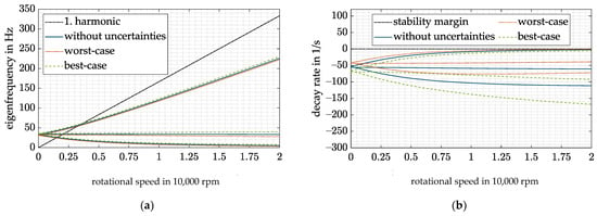
Figure 10.
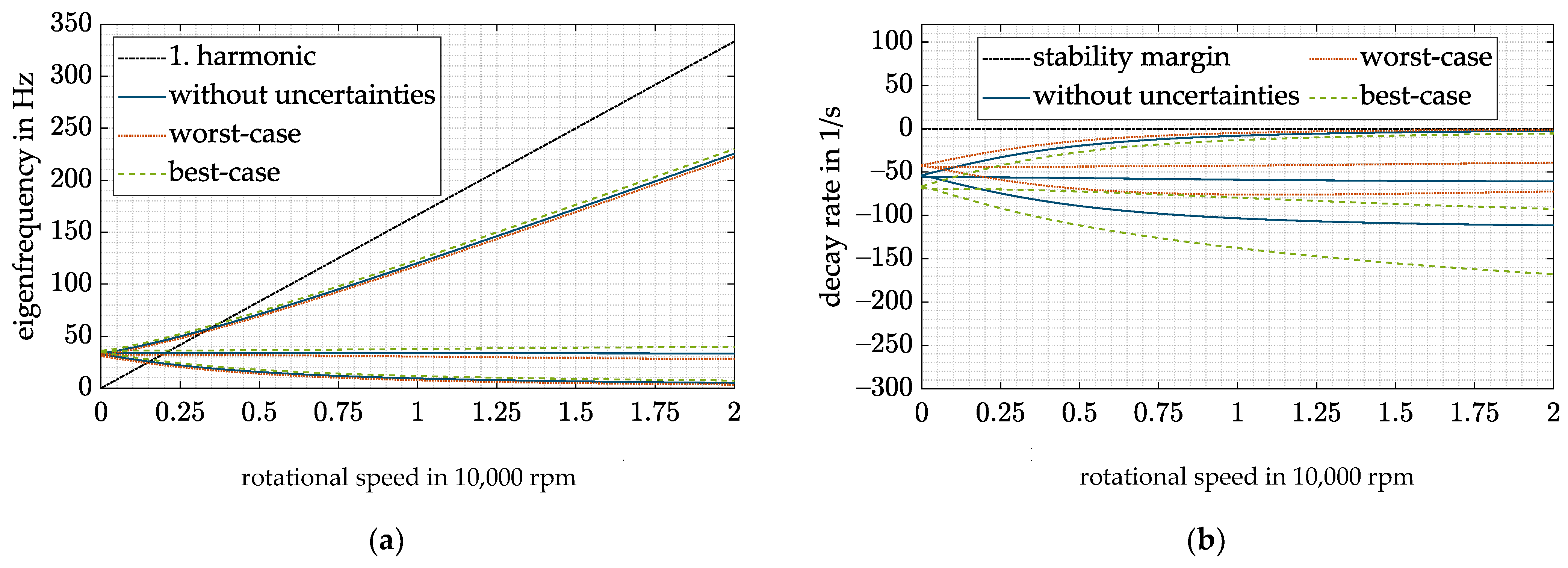
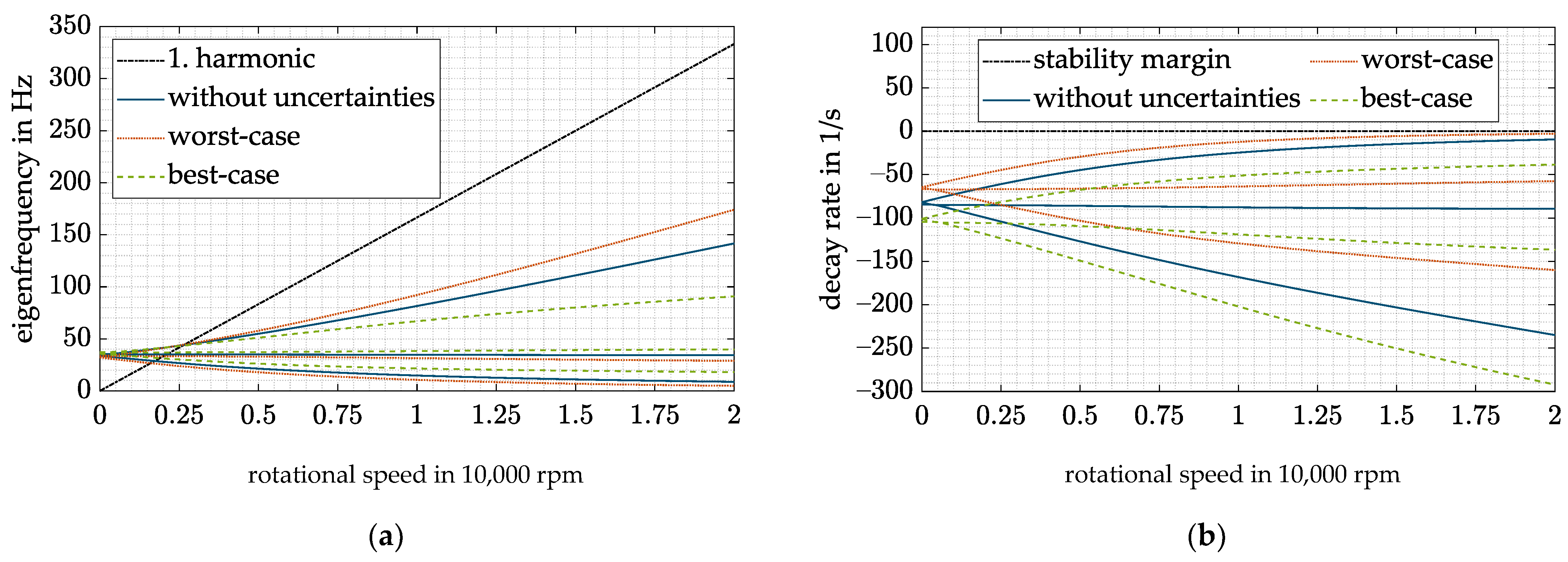
DVFC for the best- and worst-case combinations of all uncertainties: (a) Campbell diagram; (b) decay rate.
Worst- and best-case combinations of all four uncertainties are plotted against the “ideal” behavior without any uncertainties. In the worst case, all uncertainties lead and to overestimate and and thus to reduce the desired closed-loop stiffness and damping . Consequently, the eigenfrequencies and decay rates of the rigid-body modes also drop. Thus, the critical precession drops below the desired level of 5 Hz and is insufficiently damped. No instability occurs with the presently assumed uncertainties. However, higher uncertainties could yield an unstable precession (decay rate > 0). The opposite behavior occurs if and are underestimated, and no instability of the precession can occur.
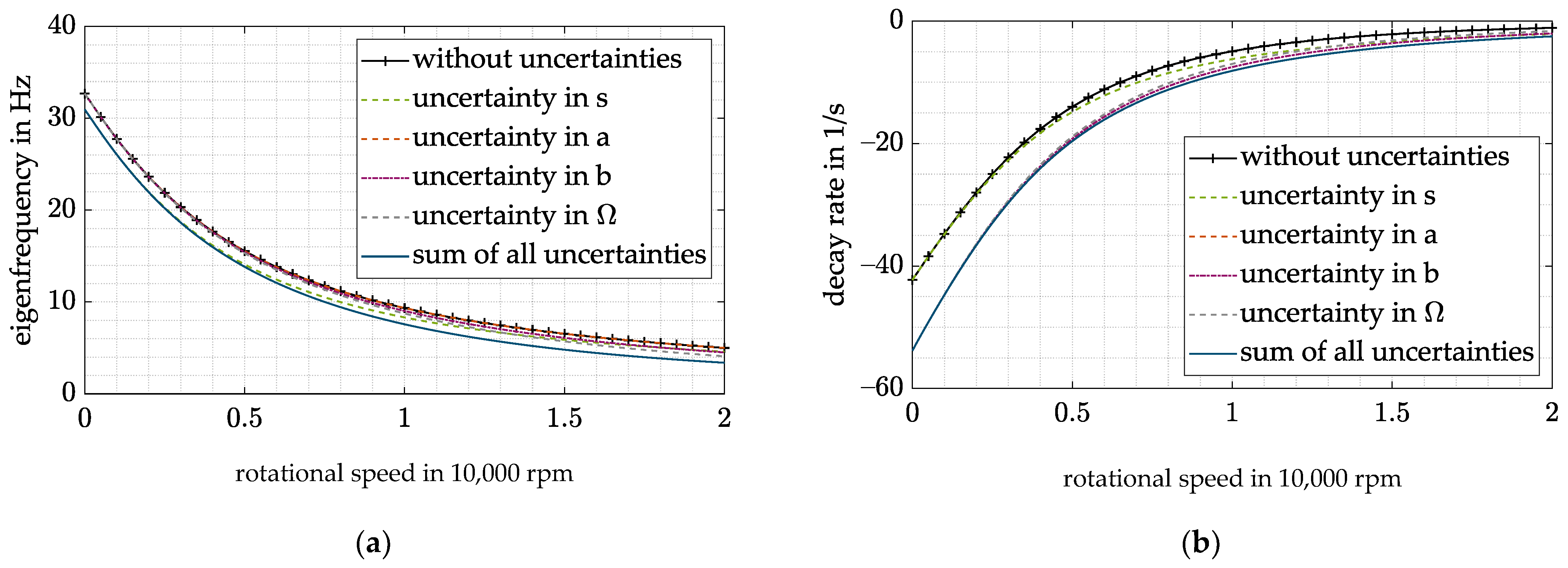
In the next step, the influence of the individual uncertainties is investigated. Figure 11 shows the influence of the different uncertainties on the precession mode and the decay rate. The analysis is done for the worst-case combination of all uncertainties since it has the highest relevance for the design. All uncertainties except result in an increase in the eigenfrequencies and decay rates with rising rotational speed starting with no shift at 0 rpm since they depend linearly or quadratically on the rotational speed. has the greatest impact of all uncertainties, whereas the effect of remains quite low. In contrast, an uncertainty in starts with a shift that varies with the rotational speed. Therefore, the resulting impact is quite high for low rotational speeds.
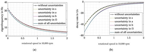
Figure 11.
Precession mode with DVFC for worst-case combination of all uncertainties: (a) eigenfrequency; (b) decay rate.
Since the uncertainties can vary between the best and worst case, the worst case must be considered in the controller design; hence, and have to overcome the uncertainty-induced drop in stiffness and damping.
The resulting closed-loop system behavior with a worst-case design and best-case uncertainties is shown in Figure 12. It constitutes the highest frequency passing of the resonances and hence the lowest operating range to be achieved with such a controller design in presence of the presented uncertainties.
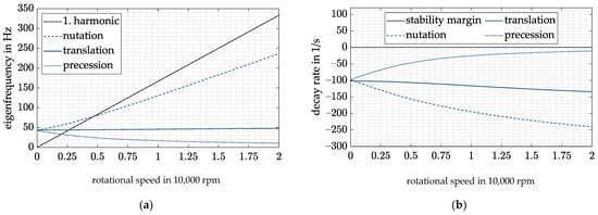
Figure 12.
DVFC and worst-case design for best-case combination of all uncertainties: (a) Campbell diagram; (b) decay rate.
As the control law in Equation (27) was set up by the means of different descriptive equations with varying numbers of simplifications, it is associated with a few more uncertainties. For the sake of completeness, their influence on the controlled system will be dealt with subsequently.
The linearized force–current relation in Equation (1) neglects magnetic leakage flux, the magnetization of the iron itself and therefore nonlinear material effects such as saturation and hysteresis as well as eddy currents. Fortunately, the saturation of the iron can be avoided by the means of an actuator design with respect to the maximum magnetic flux density which should be below the saturation magnetic flux density . Thus, never exceeds . If the magnetization of the iron and the magnetic leakage flux are neglected in Equation (1), the resulting force will be overestimated (see [36]). This means that the magnetic bearing factors and will also be overestimated. Looking back at the DVFC, this uncertainty has nearly the same influence on the system as an uncertainty in since both can reduce and and therefore reduce the resulting closed-loop stiffness and damping of the magnetic bearing. Since the quantities of the mentioned uncertainties highly depend on the bearing geometry and their effects on the system are similar to those of , they are not specified in detail.
6. Combination of Decentralized Variable Feedback Control and Cross Feedback Control
With the new controller design introduced in Section 5, the operating range of the flywheel is nearly the same as without diametral enlargement. An even wider range could be accomplished if the gyroscopic cross-coupling would also be compensated. As already outlined in Section 4, this could be done with a cross feedback control. Unfortunately, the gyroscopic cross-coupling cannot be compensated at all rotation speeds in presence of diametral enlargement (see Section 4). Thus, the compensation only holds in a tight speed range. This drawback could be circumvented if equals as was done for the DVFC:
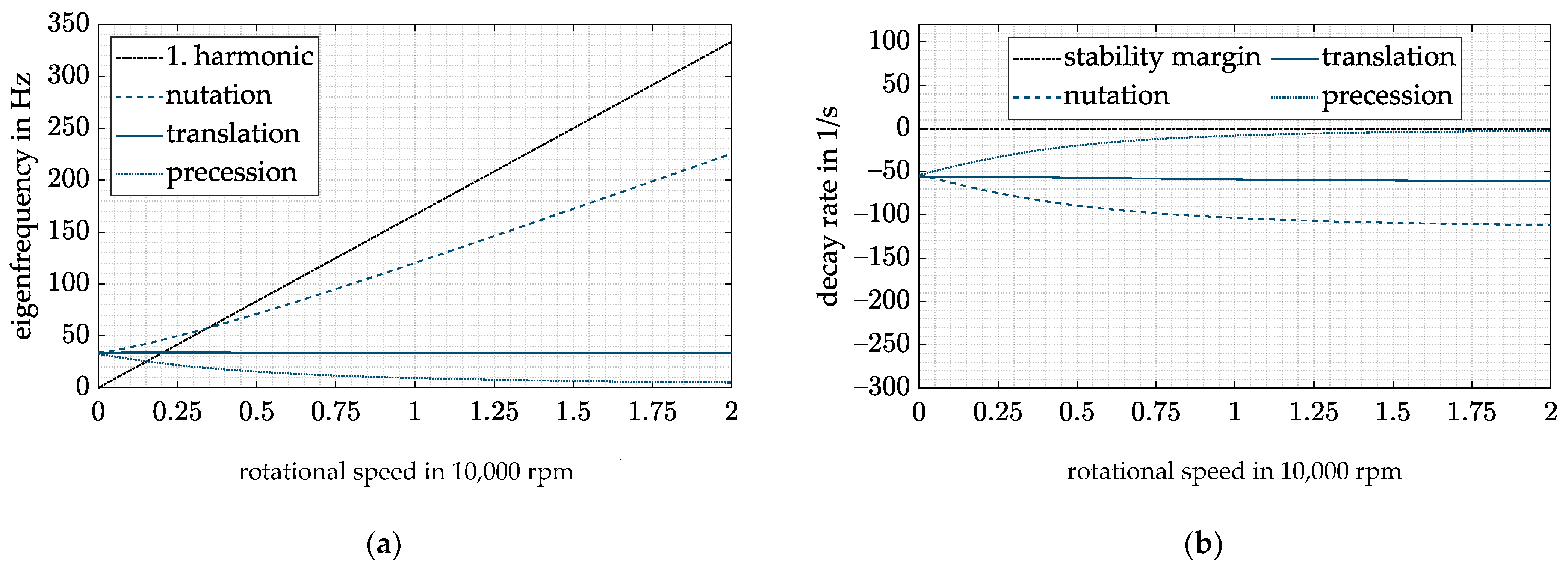
resulting in compensation at all rotational speeds linearly dependent on the attenuation factor . Now both control strategies, the extended CFC and the DVFC, can be combined to further increase the operating range of the flywheel. The resulting closed-loop behavior is shown in Figure 13.
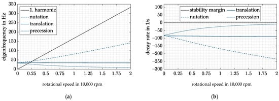
Figure 13.
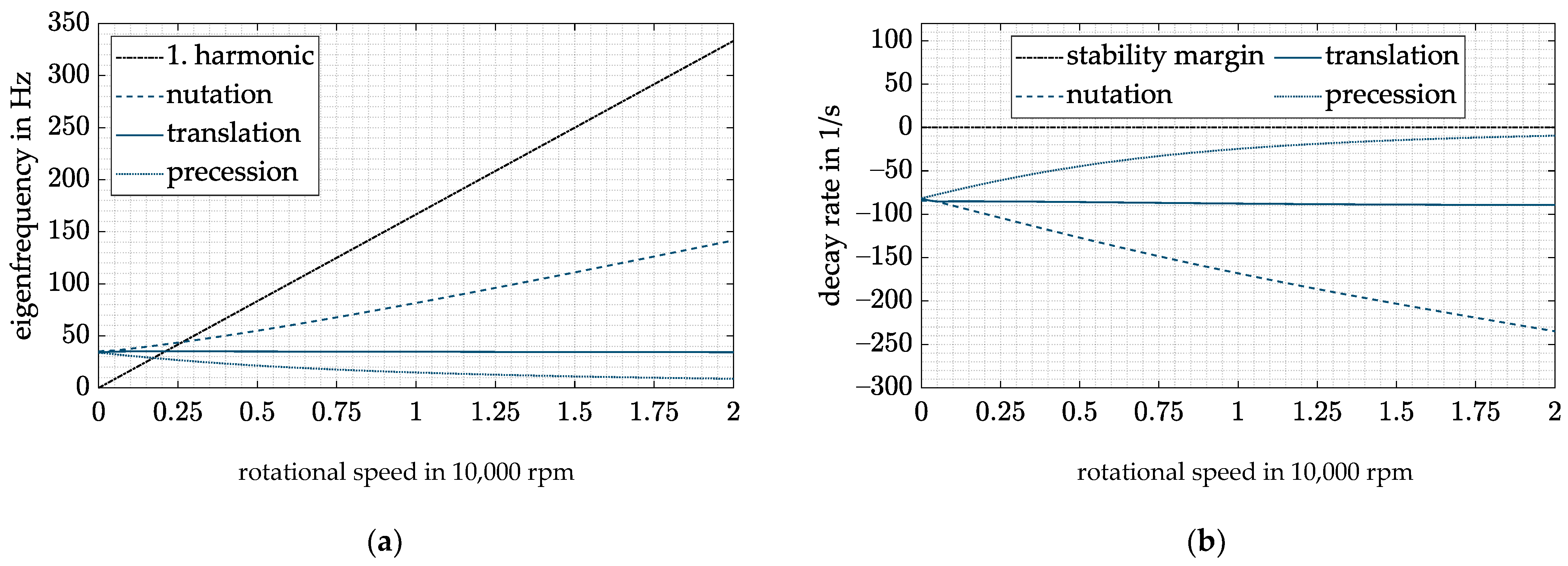
Extended CFC and DVFC with : (a) Campbell diagram; (b) decay rate.
With the help of both control strategies, the precession frequency can be held above 5 Hz at the maximum rotational speed without forcing all other eigenfrequencies to rise significantly. Thus, all rigid-body modes lie below 150 Hz, resulting in an even higher operating range than without diametral enlargement of the rotor.
Looking back at Equation (28), the postulated identity between and does not hold in presence of uncertainties as already elaborated for the DVFC. With the already introduced uncertainties , , , in and and now in ,
The following closed-loop behavior is given again for best- and worst-case combinations of all uncertainties in Figure 14.
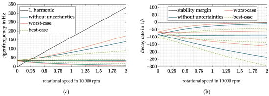
Figure 14.
Extended CFC and DVFC with for best- and worst-case combinations of all uncertainties: (a) Campbell diagram; (b) decay rate.
Here again, a worst-case design was applied; hence, the values of the desired stiffness and damping . and . were chosen to keep the precession eigenfrequency above 5 Hz and to limit the amplitude of the sensitivity function to the desired level of 10 dB for all possible combinations of the uncertainties.
Looking back at Figure 13, a far higherompensation of the gyroscopic cross-coupling could be achieved with the present controller, resulting in a higher operating range of the flywheel. Unfortunately, the impact of possie uncertainties on the closed-loop behavior rises with increasing compensation, e.g., higher attenuation factor . A further decrease in the rigid-body mode eigenfrequencies could therefore be achieved if the uncertainties would hold in a smaller interval.
Nevertheless, the operating range concerning the given uncertainties and an attenuation factor of 0.5 could be widened by approximately 1500 rpm compared to the already improved DVFC controller. In addition, the decay rates are reduced by the combination of both control strategies (see Figure 12 and Figure 14).
7. Conclusions
Flywheel rotors normally have highly gyroscopic behavior. In addition, the air gap changes due to rotor enlargement under rotation. Especially for outer rotor systems, this leads to a change in the dynamic behavior of the system. Compared to inner rotors, the enlargement of outer rotors leads to an increase in the magnetic bearing air gap and thus to a decrease in the force and force slew rate of the AMB. When using a DFC controller, the enlargement leads to speed-dependent stiffness . and damping . of the AMB. To compensate the reduced stiffness, a high feedback gain has to be chosen, which increases the critical speeds and thus reduces the operating range of the system. In addition, a high damping ratio at low speeds is necessary, leading to overcompensation and high utilization of the amplifier. These drawbacks for the control of highly gyroscopic outer rotor systems with diametral enlargement are compensated with the control strategy proposed by the authors. The proposed control strategy consists of a combination of a cross feedback control for the compensation of the gyroscopic coupling and decentralized variable feedback control for the compensation of the diametral enlargement.
The main advantages of the proposed control strategy are as follows:
- By using the cross feedback control, the gyroscopic-induced split-up of the conical body eigenfrequencies is reduced and the critical speeds shift towards lower rotational speeds, thus leading to a higher operational range.
- Speed-dependent feedback terms P(Ω) and D(Ω) are used to compensate the speed dependency of the stiffness and damping of the AMB. As a result, the natural frequency of the rigid-body eigenmodes can be shifted to lower frequencies and the operating range of the system is increased. At the same time, the damping at low speeds is reduced, and thus no overcompensation occurs.
- Even with uncertainties in the estimated air gap, the proposed controller can stabilize the system.
- Due to this combined controller, the critical speed of the nutation can be reduced by approximately 4500 rpm for the investigated system. At the same time, the undesired high decay rate at low frequencies is avoided.
- To change from a conventional DFC to the proposed controller, the rotational speed has to be measured. However, in most systems, the rotational speed is measured anyway, and therefore no increased measurement effort is necessary for the new control approach.
In further studies, the analytical results obtained here have to be verified by experimental investigations.
Author Contributions
Conceptualization, M.R.; data curation, T.H.; formal analysis, T.H. and M.R.; funding acquisition, S.R.; investigation, T.H. and M.R.; methodology, T.H. and M.R.; project administration, S.R.; resources, S.R.; software, T.H. and M.R.; supervision, S.R.; validation, T.H.; visualization, T.H. and B.S.; writing—original draft, T.H. and B.S.; writing—review and editing, B.S. All authors have read and agreed to the published version of the manuscript.
Funding
The results are obtained within the project “Kostenreduktion bei gleichzeitiger Erhöhung der Verfügbarkeit und Effizienz von Schwungmassenspeichern in Außenläufer-Bauform” with the grant number 03EI3000A which is founded by the Federal Ministry for Economic Affairs and Energy on the basis of a decision by the German Bundestag.
Institutional Review Board Statement
Not applicable.
Informed Consent Statement
Not applicable.
Data Availability Statement
The data presented in this study are available on request from the corresponding author.
Acknowledgments
We acknowledge support from the Deutsche Forschungsgemeinschaft (DFG, German Research Foundation) and the Open Access Publishing Fund of the Technical University of Darmstadt.
Conflicts of Interest
The authors declare no conflict of interest.
References
- Amiryar, M.; Pullen, K. A Review of Flywheel Energy Storage System Technologies and Their Applications. Appl. Sci. 2017, 7, 286. [Google Scholar] [CrossRef] [Green Version]
- Franz, D.; Richter, M.; Schneider, M.; Rinderknecht, S. Homopolar Active Magnetic Bearing Design for Outer Rotor Kinetic Energy Storages. In Proceedings of the 2019 IEEE International Electric Machines & Drives Conference (IEMDC), San Diego, CA, USA, 12–15 May 2019; pp. 774–778, ISBN 978-1-5386-9350-6. [Google Scholar]
- Schneider, M. Ganzheitlicher Modellbasierter Entwurf von Kinetischen Energiespeichern in Außenläuferbauform, (Translated: Holistic Model Based Design of Outer Rotor Kinetic Energy Storage Systems); Shaker Verlag: Düren, Germany, 2019; ISBN 9783844066579. [Google Scholar]
- Quurck, L.; Richter, M.; Schneider, M.; Franz, D.; Rinderknecht, S. Design and practical Realization of an innovative Flywheel Concept for industrial Applications. Tech. Mech. 2017, 37, 151–160. [Google Scholar] [CrossRef]
- Quurck, L.; Franz, D.; Schüßler, B.; Rinderknecht, S. Planetary Backup Bearings for High Speed Applications and Service Life Estimation Methodology. Mech. Eng. J. 2017, 4, 17-00010. [Google Scholar] [CrossRef] [Green Version]
- Schüßler, B.; Hopf, T.; Rinderknecht, S. Drop-Downs of an Outer Rotor Flywheel in Different Planetary Touch-Down Bearing Designs. Actuators 2022, 11, 30. [Google Scholar] [CrossRef]
- Cao, H.; Zhang, X.; Chen, X. The Concept and Progress of Intelligent Spindles: A Review. Int. J. Mach. Tools Manuf. 2017, 112, 21–52. [Google Scholar] [CrossRef]
- Kern, S.; Schiffler, A.; Nordmann, R.; Abele, E. Modelling and Active Damping of a Motor Spindle with Speed-Dependent Dynamics. In Proceedings of the 9th International Conference on Vibrations in Rotating Machinery, Exeter, UK, 8–10 September 2008. [Google Scholar]
- Knospe, C.R. Active Magnetic Bearings for Machining Applications. Control Eng. Pract. 2007, 15, 307–313. [Google Scholar] [CrossRef]
- Li, D.; Cao, H.; Shi, F.; Zhang, X.; Chen, X. Model Predictive Control Based Chatter Suppression in Milling Process via Piezoelectric Stack Actuators. Procedia CIRP 2018, 78, 31–36. [Google Scholar] [CrossRef]
- Li, D.; Cao, H.; Zhang, X.; Chen, X.; Yan, R. Model predictive control based active chatter control in milling process. Mech. Syst. Signal Processing 2019, 128, 266–281. [Google Scholar] [CrossRef]
- Kuseyri, İ.S. Robust control and unbalance compensation of rotor/active magnetic bearing systems. J. Vib. Control 2012, 18, 817–832. [Google Scholar] [CrossRef]
- Siva Srinivas, R.; Tiwari, R.; Kannababu, C. Application of active magnetic bearings in flexible rotordynamic systems—A state-of-the-art review. Mech. Syst. Signal Processing 2018, 106, 537–572. [Google Scholar] [CrossRef]
- Schüßler, B.; Hopf, T.; Fanz, D.; Schneider, M.; Rinderknecht, S. High Speed Drop Down in a Planetary Touch-Down Bearing of an Outer Rotor Flywheel System. In Proceedings of the SIRM 2021, The 14th International Conference on Dynamics of Rotating Machines, Gdańsk, Poland, 17–19 February 2021. [Google Scholar]
- Lyu, X.; Di, L.; Yoon, S.Y.; Lin, Z.; Hu, Y. A platform for analysis and control design: Emulation of energy storage flywheels on a rotor-AMB test rig. Mechatronics 2016, 33, 146–160. [Google Scholar] [CrossRef]
- Ahrens, M.; Kucera, L.; Larsonneur, R. Performance of a magnetically suspended flywheel energy storage device. IEEE Trans. Contr. Syst. Technol. 1996, 4, 494–502. [Google Scholar] [CrossRef]
- Tang, J.; Zhao, S.; Wang, Y.; Wang, K. High-speed Rotor’s Mechanical Design and Stable Suspension Based on Inertia-ratio for Gyroscopic Effect Suppression. Int. J. Control Autom. Syst. 2018, 16, 1577–1591. [Google Scholar] [CrossRef]
- Ahrens, M.; Kucera, L. Cross Feedback Control of a Magnetic Bearing System: Controller Design Considering Gyroscopic Effects. In Proceedings of the 3rd International Symposium on Magnetic Suspension Technology, Tallahassee, FL, USA, 13–15 December 1995; pp. 177–191. [Google Scholar]
- Fang, J.; Xu, X.; Xie, J. Active vibration control of rotor imbalance in active magnetic bearing systems. J. Vib. Control 2015, 21, 684–700. [Google Scholar] [CrossRef]
- Hutterer, M.; Hofer, M.; Nenning, T.; Schrödl, M. LQG Control of an Active Magnetic Bearing with a Special Method to consider the Gyroscopic Effect. In Proceedings of the ISMB 14, International Symposium on Magnetic Bearings, Linz, Austria, 11–14 August 2014; pp. 54–59. [Google Scholar]
- Hutterer, M.; Hofer, M.; Schrodl, M. Decoupled control of an active magnetic bearing system for a high gyroscopic rotor. In Proceedings of the 2015 IEEE International Conference on Mechatronics (ICM), Nagoya, Japan, 6–8 March 2015; pp. 210–215, ISBN 978-1-4799-3633-5. [Google Scholar]
- Hutterer, M.; Schrödl, M. Control of Active Magnetic Bearings in Turbomolecular Pumps for Rotors with Low Resonance Frequencies of the Blade Wheel. Lubricants 2017, 5, 26. [Google Scholar] [CrossRef] [Green Version]
- Barbaraci, G.; Pesch, A.H.; Sawicki, J.T. Experimental Investigations of Minimum Power Consumption Optimal Control for Variable Speed AMB Rotor. In Volume 8: Dynamic Systems and Control, Parts A and B. Proceedings of the ASME 2010 International Mechanical Engineering Congress and Exposition, Vancouver, British Columbia, Canada, 12–18 November 2010; ASMEDC, 11122010; ASME: New York, NY, USA, 2010; pp. 1047–1056. ISBN 978-0-7918-4445-8. [Google Scholar]
- Steyn, S.J.M.; van Schoor, G.; van Vuuren, P.A. Multivariable H∞ Control for an Active Magnetic Bearing Flywheel System. In Proceedings of the UKACC International Conference on CONTROL 2010, Coventry, UK, 7–10 September 2010; Institution of Engineering and Technology: Stevenage, UK, 2010; pp. 1014–1019, ISBN 978-1-84600-038-6. [Google Scholar]
- Zhang, W.; Cheng, L.; Zhu, H. Suspension Force Error Source Analysis and Multidimensional Dynamic Model for a Centripetal Force Type-Magnetic Bearing. IEEE Trans. Ind. Electron. 2020, 67, 7617–7628. [Google Scholar] [CrossRef]
- Kuseyri, İ.S. Adaptive Vibration Control of Rotors with Active Magnetic Bearings. J. Vib. Eng. Technol. 2017, 5, 159–164. [Google Scholar]
- Tang, J.; Ning, M.; Cui, X.; Wei, T.; Zhao, X. PIDNN control for Vernier-gimballing magnetically suspended flywheel under nonlinear change of stiffness and disturbance. Proc. Inst. Mech. Eng. Part I J. Syst. Control Eng. 2021, 235, 1100–1112. [Google Scholar] [CrossRef]
- Apkarian, P.; Gahinet, P.; Buhr, C. Multi-model, multi-objective tuning of fixed-structure controllers. In Proceedings of the 2014 European Control Conference (ECC), Strasbourg, France, 24–27 June 2014; pp. 856–861. [Google Scholar]
- Magnetic Bearings: Theory, Design, and Application to Rotating Machinery; Maslen, E.H.; Schweitzer, G. (Eds.) Springer: Berlin/Heidelberg, Germany, 2009; ISBN 978-3-642-00496-4. [Google Scholar]
- Genta, G. Dynamics of Rotating Systems; Springer: New York, NY, USA, 2005; ISBN 9780387286877. [Google Scholar]
- Gasch, R.; Nordmann, R.; Pfützner, H. Rotordynamik, (Translated: Rotordynamic), 2nd ed.; Springer: Berlin/Heidelberg, Germany, 2006; ISBN 978-3-540-41240-3. [Google Scholar]
- Arnold, S.M.; Saleeb, A.F.; Al-Zoubi, N.R. Deformation and life analysis of composite flywheel disk systems. Compos. Part B Eng. 2002, 33, 433–459. [Google Scholar] [CrossRef]
- Meeker, D.C.; Maslen, E.H.; Noh, M.D. A wide bandwidth model for the electrical impedance of magnetic. In Proceedings of the Third International Symposium on Magnetic Suspension Technology, Tallahassee, FL, USA, 13–15 December 1996; Groom, N.J., Britcher, C.P., Eds.; NASA: Washington, WA, USA, 1996; pp. 387–401. [Google Scholar]
- Schoppa, A.; Delarbre, P. Soft Magnetic Powder Composites and Potential Applications in Modern Electric Machines and Devices. IEEE Trans. Magn. 2014, 50, 1–4. [Google Scholar] [CrossRef]
- Seifert, R.; Hofmann, W. Completion of analytical model of active magnetic thrust bearings including asymmetric air gap field between mixed materials. Mech. Eng. J. 2017, 4, 16–00696. [Google Scholar] [CrossRef]
- Traxler, A. Eigenschaften und AUSLEGUNG von Berührungsfreien Elektromagnetischen Lagern, (Translated: Characteristics and Design of Electromagnetic Bearings); ETH Zurich: Zurich, Switzerland, 1986. [Google Scholar]
- Bleuler, H. Decentralized Control of Magnetic Rotor Bearing Systems; ETH Zurich: Zurich, Switzerland, 1984. [Google Scholar]
- Li, G.; Maslen, E.H.; Allaire, P.E. A Note on ISO AMB Stability Margin. In Proceedings of the ISMB 10, International Symposium on Magnetic Bearings, Martigny, Switzerland, 21–23 August 2006. [Google Scholar]
- Che, J.; Zhu, Y.; Zhou, D.; He, X. Active fault tolerant control design using switching linear parameter varying controllers with inexact fault-effect parameters. Int. J. Robust Nonlinear 2022. [Google Scholar] [CrossRef]
- Peng, C.; Zhu, M.; Wang, K.; Ren, Y.; Deng, Z. A Two-Stage Synchronous Vibration Control for Magnetically Suspended Rotor System in the Full Speed Range. IEEE Trans. Ind. Electron. 2020, 67, 480–489. [Google Scholar] [CrossRef]
Publisher’s Note: MDPI stays neutral with regard to jurisdictional claims in published maps and institutional affiliations. |
© 2022 by the authors. Licensee MDPI, Basel, Switzerland. This article is an open access article distributed under the terms and conditions of the Creative Commons Attribution (CC BY) license (https://creativecommons.org/licenses/by/4.0/).

